A QUARTERLY PUBLICATION FOR WESTERN DAM ENGINEERS …
24
VOLUME 3 ISSUE 1 February 2015 Introduction……………………………………….….. 1 Sinkholes: The Hole Story…Issues are Deeper than you Think………………………………………………2 Letting it All Out: Hydraulic Design of Outlet Works………………………....………….8 Soil Characterization (Part 3) - Shear Strength Characterization for Slope Stability Analyses …………………………………………………………………………...…………. 15 1 A QUARTERLY PUBLICATION FOR WESTERN DAM ENGINEERS Comments/Feedback/Suggestions? Email Colorado Dam Safety to submit feedback on Articles. Please use article title as the subject of the email. Upcoming ASDSO Webinar Dam Safety Training: • Designing Slope Protection for Dams and Levees, Mar 9, 2015 • Intro to Earthquake Engineering for Dams, April 7, 2015 Upcoming Classroom Technical Seminars: • Dam Failures and Lessons Learned, Mar 3-5, 2015, P. Schweiger, J. Cyganiewicz, & D. Miller, New Orleans, LA • HEC-HMS, Mar 31 – April 2, Dr. A. Miller & A. Hess, Seattle, WA ASDSO Training Website Link Need help reviewing or writing dam specifications? Download Dam Specifications Review Tool here In this issue of the Western Dam Engineering Technical Note, we present articles on sinkholes related to dams, outlet works design considerations, and shear strength characterization. Most of these articles draw on previously published articles in this newsletter. This newsletter is meant as an educational resource for civil engineers who practice primarily in rural areas of the western United States. This publication focuses on technical articles specific to small and medium dams. It provides general information. The reader is encouraged to use the references cited and engage other technical experts as appropriate. The Western Dam Engineering Technical Note is sponsored by the following agencies: Wyoming State Engineer’s Office Colorado Division of Water Resources Montana Department of Natural Resources This Technical Note was compiled, written, and edited by AECOM in Denver, Colorado Funding for the Technical Note has been provided by the FEMA National Dam Safety Act Assistance to States grant program. Article Contributors: AECOM: Jessie Drayton; Chris Shrimpton; Julie Heitland; Jennifer Williams, PE; John France, PE; Frank Lan, PhD, PE Editorial Review Board: Michele Lemieux, PE, Montana Dam Safety Program Supervisor; Bill McCormick, PE, PG, Colorado Chief Dam Safety Branch; Mike Hand, PE, Wyoming Dam Safety Program; Mark Ogden, PE, Association of State Dam Safety Officials; Matthew Lindon, PE, Loughlin Water Associates; and Steve Becker, PE, Natural Resources Conservation Service The material in this publication has been prepared in accordance with generally recognized engineering principles and practices, and is for general information only. The information presented should not be used without first securing competent advice from qualified professionals with respect to its suitability for any general or specific application. No reference made in this publication constitutes an endorsement or warranty thereof by AECOM or sponsors of this newsletter. Anyone using the information presented in this newsletter assumes all liability arising from such use.
Transcript of A QUARTERLY PUBLICATION FOR WESTERN DAM ENGINEERS …

VOLUME 3
ISSUE 1
February 2015
Introduction……………………………………….….. 1 Sinkholes: The Hole Story…Issues are Deeper than you Think………………………………………………2
Letting it All Out: Hydraulic Design of Outlet Works………………………....………….8 Soil Characterization (Part 3) - Shear Strength Characterization for Slope Stability Analyses …………………………………………………………………………...…………. 15
1
A QUARTERLY PUBLICATION FOR WESTERN DAM ENGINEERS
Comments/Feedback/Suggestions? Email Colorado Dam Safety to submit feedback on Articles. Please use article title as the subject of the email.
Upcoming ASDSO Webinar Dam Safety Training: • Designing Slope Protection for Dams and Levees, Mar 9, 2015 • Intro to Earthquake Engineering for Dams, April 7, 2015
Upcoming Classroom Technical Seminars: • Dam Failures and Lessons Learned, Mar 3-5, 2015,
P. Schweiger, J. Cyganiewicz, & D. Miller, New Orleans, LA • HEC-HMS, Mar 31 – April 2, Dr. A. Miller & A. Hess,
Seattle, WA ASDSO Training Website Link
Need help reviewing or writing dam specifications? Download Dam Specifications Review Tool here
In this issue of the Western Dam Engineering Technical Note, we present articles on sinkholes related to dams, outlet works design considerations, and shear strength characterization. Most of these articles draw on previously published articles in this newsletter. This newsletter is meant as an educational resource for civil engineers who practice primarily in rural areas of the western United States. This publication focuses on technical articles specific to small and medium dams. It provides general information. The reader is encouraged to use the references cited and engage other technical experts as appropriate.
The Western Dam Engineering Technical Note is sponsored by the following agencies:
Wyoming State Engineer’s Office Colorado Division of Water Resources Montana Department of Natural
Resources
This Technical Note was compiled, written, and edited by AECOM in Denver, Colorado
Funding for the Technical Note has been provided by the FEMA National Dam Safety Act Assistance to States grant program.
Article Contributors: AECOM: Jessie Drayton; Chris Shrimpton; Julie Heitland; Jennifer Williams, PE; John France, PE; Frank Lan, PhD, PE Editorial Review Board: Michele Lemieux, PE, Montana Dam Safety Program Supervisor; Bill McCormick, PE, PG, Colorado Chief Dam Safety Branch; Mike Hand, PE, Wyoming Dam Safety Program; Mark Ogden, PE, Association of State Dam Safety Officials; Matthew Lindon, PE, Loughlin Water Associates; and Steve Becker, PE, Natural Resources Conservation Service
The material in this publication has been prepared in accordance with generally recognized engineering principles and practices, and is for general information only. The information presented should not be used without first securing competent advice from qualified professionals with respect to its suitability for any general or specific application. No reference made in this publication constitutes an endorsement or warranty thereof by AECOM or sponsors of this newsletter. Anyone using the information presented in this newsletter assumes all liability arising from such use.

2
SINKHOLES: The Hole Story …Issues are Deeper than you Think! Introduction A sinkhole is a depression or void caused by collapse of surface materials due to movement of water removing underlying material. When this removal of material forms an enlarging tunnel, it is referred to as backward erosion piping. Sinkholes are often an indication that it is occurring.
Figure 1: Sinkhole formation (from Reclamation Best Practices Fig 26-3a)
The most common condition causing sinkholes to occur in or near dams is concentrated seepage through voids or cracks causing material to move. This can occur due to:
• Karstic foundation that has voids due to solutioning
• Loose or poorly graded materials that include cobbles or boulders and poor compaction
• Poor treatment of foundation during construction, where there is a prevalence of joints
• Leak in pipe that penetrates the dam, creating increased seepage
• Animal burrows that create shortened seepage paths when they become submerged
• Differential settlement creating cracks or voids • Construction defects creating cracks or voids
There are several repair options depending on the cause and size of the sinkhole. Sinkholes can be benign and self-healing, but are generally the first sign of a developing problem that could progress to a major dam safety issue if not addressed in a timely manner.
Prevalence in Small Dams Construction of small dams increased in the U.S. in the early 1900s due to an increased demand for water in agricultural and mining actives. At the time there was a lack of appreciation of the complexities associated with design and construction of small dams. This led to limited engineering with not enough emphasis on subsurface exploration, design of filters and cutoffs, treatment of foundation and quality control during construction (gradation and compaction). Small dams typically have less foundation investigation and preparation due to the smaller head. However, with smaller cross sections gradients can still be high. In addition, more frequent cycles of high and low pool levels can intensify issues such as cracking or animal burrows.
In addition, failure of small dams is also assumed to be less catastrophic and frequent inspection and dam safety protocols may be de-emphasized. Signs of issues may go unnoticed for long periods of time. If issues are noticed, a small repair may be applied without proper engineering. If such repairs do not treat the fundamental issue, reoccurrence is inevitable. Signs of a sinkhole may appear to be only a small surficial depression easily repaired with placement of fill. However, a seepage pipe and potential failure path may exist just below the surface, readily available to promote material transport when the reservoir level rises.
Photo 1: Example of small depression that may go unnoticed (Young Creek Dam)

3
Signs of Sinkhole Activity Sinkholes can often be identified by whirlpools forming upstream of the dam. Whirlpools may be significant and easily observable (Photo 2), or they may be slight enough that they simply result in leaves or grasses floating in a circular pattern, which is the more common scenario.
Photo 2: Whirlpool upstream of dam (U.S Forest Service)
Excessive seepage on abutments, embankment, toes, or further downstream from the dam, can signal an issue. Muddy seepage downstream can be an indication that transportation and sediment is occurring and material is being piped out of the dam. Holes and depressions on or near the crest can signal uneven settling and material transport below grade. During low pool, small depressions and holes upstream of the dam, on the embankment, abutments, or even reservoir banks can be indications of sinkhole formation.
Photo 3: Sinkhole on upstream embankment (Paxton Dam)
Potential Breach of Dam Sinkhole activity can lead to a dam breach if not treated. The overburden or embankment migrates into voids due to seepage from the reservoir. Backward erosion piping occurs causing sediment transport out of the foundation or dam. The material transport is not stopped by a filter or cutoff and a sinkhole forms upstream of the dam as the erosion increases. In some situations, the failure path is high enough that the erosion only results in a loss of water storage above the sinkhole. However, more commonly, the sinkhole and associated pipe is low enough to mobilize sufficient material to undermine the embankment, causing a full breach with possible downstream consequences.
Fixes Upon identifying a sinkhole, the first and most effective action to be taken is to lower the reservoir pool. Any reduction in gradient will help slow erosion but lowering the pool to below the sinkhole is ideal if possible. Depending on the size and cause of the sinkhole, several repair methods are possible.
Clay Blanket - If the sinkhole is due to a localized issue, such as loose or poorly graded material, excavation of the sinkhole and surrounding area and placement of a clay layer can be a simple repair. The thickness of the clay layer should be based on gradients and material properties and determined by a soils engineer. The clay layer should be covered by native soil or rocks to protect the clay from erosion. Compaction of the excavated area before placement as well as compaction of the clay layer is important. To use this method effectively, there should be no signs of a pipe leading from the sinkhole, as the clay may erode into the pipe upon raising the reservoir.
Reverse Filter - For a larger sinkhole, another repair option may be the placement of a more robust reverse filter. The sinkhole area should be excavated to remove voids and loose material as well as expose the flow path if possible. The number of layers of the filter varies based on depth needed and materials available, but the filter should have a minimum of three layers below the native ground material. Rock should be placed at the bottom of the excavation followed by gravels then sand, before being covered with native

4
overburden and riprap. The gradation specifics depend on the character of the surrounding soils. Proper compaction is required for all layers. See Figure 2 for an example reverse filter.
Geotextile, Geosynthetic Clay Liner, or Geomembrane - Similar to the clay blanket and reverse filter, engineered liners and fabrics can be used after excavation of the sinkhole. Native material should be placed over the liner or fabric. Liners and fabrics can be used in conjunction with reverse graded filters as another layer of protection.
Grouting - Grouting is a repair option especially effective if widespread cracks, voids, and joints are found within the foundation or embankment. Grout is generally applied with low pool and under dry conditions so that the grout can set up. Various mixes are available for grouting and selection of properties is dependent on soil conditions, size of sinkhole, and environmental conditions. Mixtures with fluid-like consistency (low viscosity) take longer to set up but are likely to penetrate more deeply and into smaller voids. Thicker, more viscous mixtures are quicker to set up but may not be as effective at filling the void. A combination of mixes can be used to fill the smaller and deeper areas with fluid grout and then the larger void with more viscous grout. Depending on the size of the sinkhole, soil conditions, and the grout material, the grout can be gravity fed (pipe placed in hole for funneling) or injected under pressure. The hole and pipe are often flushed with water to remove debris and loose material prior to application of grout. When setup is complete, the area should be backfilled with native soil and rocks/riprap placed to protect the grout near the surface.
There are two general families of grout: cement grouts and chemical grouts. Each family has primary grout sub-types. Primary types of cement grout include ordinary Portland cement (OPC) and ultrafine cements. Primary types of chemical grouts include silicates (typically sodium silicates), acrylic gels (acrylamide, acrylic, and acrylates), and polyurethane foams (hydrophilic or hydrophobic). Each grout type varies in appropriate application based on their unique characteristics including viscosity, set-up time, expansion, flexibility, strength, life span, and cost. Due
to the wide array of grout products available and the complexity of selecting the appropriate grout mix, a qualified grouting engineer or contractor should be engaged to provide site-specific recommendations.
Photo 4: Application of chemical urethane grout (Big Battlement Dam)
Below is a list of grout types commonly used in geotechnical void-filling applications:
• Acrylamide Grout – Highly impermeable and low viscosity. Changes from liquid to a solid in a controllable set-up time. Acrylamides generally have a long life span (100 years+). [5]
• Polyurethane Chemical Resin Grout –Hydrophilic foams react with water to form an expansive flexible foam or non-expansive gel that hardens. It can be used for grouting applications where dry conditions are not possible or too costly. Hydrophobic expansive foams require little water to react and easily withstand wet/dry cycles. Polyurethane foam generally has a life span between 75 and 100 years. [5]
• Epoxy Grouts – Suitable for underwater applications
• Ultrafine Cementitious Grout – Cement grouts generally cost less than chemical grouts and have higher strength. Cement grouts have higher viscosity and faster set-up times, which can be controlled to a degree with water and additives. Life span is typically 100 years+. [5]

5
Case Studies – Repairs Fish Lake, CO –This dam has a history of seepage along the downstream toe, believed to be due to the open matrix character of the foundation rock. A sinkhole recently occurred on the upstream side of the dam near the left abutment, presumably due to voids most likely at the interface between the dam embankment and the foundation. The sinkhole was first observed during a routine inspection in July 2011. Further inspection and dye testing by a geotechnical engineer in October 2011 confirmed the location of the entrance and exit point of the seepage flowing from the toe of the embankment. The use of urethane grout was recommended to fill the sinkhole. Grouting took place in August 2012. The sinkhole was first cleared of rock and debris and then flushed with approximately 5 gallons of water to obtain thorough pre-wetting for the grout application.
Photo 5: Flushing of sinkhole at Fish Lake, CO
The application of the grout into the sinkhole was aided by a steel pipe and tarp to funnel the material. Stratathane ST-504 Vari-Gel Injection resin was used. Lake water was used for flushing and mixing the grout. The grout was applied in stages with three different mixes, becoming more viscous with each application. The mixes were:
• 15 water to 1 grout: 30 gallons of water applied, grout completely absorbed, poured easily.
• 10 water to 1 grout: 30 gallons of water applied, grout completely absorbed, some backing up during pouring.
• 5 water to 1 grout: 5 gallons of water applied, grout was not entirely absorbed, pipe containment was half full.
Photo 6: Final application of grout, contained within pipe (Fish Lake)
The most fluid mixture took longer to set up before the next application could be poured, but obtained the greatest penetration into voids or cracks related to the sinkhole and seepage path. The second and third application took less time to set up but obtained less penetration. All mixtures expanded upon application and the last mixture served to cap the sinkhole. After the grout had set up and cured, the pipe was removed and the area was backfilled with rock to provide protection for the grout. An inspection 6 months after the grout application found some shrinkage of the grout at ground surface, but the sinkhole appeared to be sealed. No issues have been reported around the sinkhole or in other areas of the dam since the repair.
Lake Ann, CO – Seepage 400 feet downstream of the dam has been a longstanding issue at Lake Ann. Evidence indicates water was flowing through the foundation of the dam from upstream. A sinkhole from the 1960s was repaired with a plastic liner. Deteriorated plastic was found and removed in the excavation of a more recent sinkhole in the same area. The recent sinkhole was observed at the dam approximately 15 feet upstream of the intake and 100 feet right of the outlet. The flow was approximately 0.3 cubic feet per second when initially measured in October 2014. The reservoir was immediately drained

6
to below the sinkhole to stop the flow of water through the sinkhole while repairs were developed and implemented.
Photo 7: Sinkhole when first observed at Lake Ann, CO
A reverse filter was designed and constructed to repair the sinkhole. The sinkhole area was excavated to approximately 6 feet deep, 20 feet in diameter at the surface and 9.5 feet in diameter at the bottom. The subgrade was compacted before application of the filter material. The reverse filter was constructed of five layers, each 12 inches thick followed by a layer of native material at the surface. The properties of the five layers were as follows (Layer 1 was placed at the bottom of the excavation):
1. 1.5-inch screened rock 2. No. 67 Aggregate AASHTO M43 3. 50% C33 concrete sand and 50% 3/8 inch
screened rock 4. Clayey material 5. Clayey material
(Layers 4 and 5 formed a two-foot thick compacted clay liner/cap).
Figure 2: Elevation of sinkhole repair patch

7
Photo 8: Compaction of clay layer at Lake Ann, CO
Each layer was placed in 3-inch lifts and compacted using a vibrating plate compactor. The clay layers were also compacted with a jumping jack. The repair was completed on November 28, 2014. No issues have been reported since completion.
Case Studies – Lessons Learned Anchor Dam, WY – Even with foundation treatment, some geologic conditions are always susceptible to sinkholes, and foundation treatment can do little to achieve preferred conditions. Anchor Dam is a concrete arch dam built on dolomite bedrock with carbonate karst in the abutments and gypsum karst in the foundation. The rock dissolves with groundwater over time, creating networks of cavities. During construction the cavities that were found were filled with concrete but the reservoir never held the volume of water intended. Water continuously leaks through the creek bed and under the dam. More than 50 sinkholes appeared and were plugged in the first twenty years after construction, but the reservoir continues to leak. Soon after construction, one sinkhole was reported to be approximately 300 feet in diameter and 50 feet deep. The dam still stands today but the reservoir is frequently empty and only holds water temporarily after rain and snow melt.
Scholl Dam, CO – Poor underlying soil conditions can create sinkhole issues over broad areas, making localized fixes ineffective. At Scholl dam sinkholes in the upstream abutment have been repaired continuously, but the sinkholes continue to reappear
at different locations. Repairs have included geomembrane, clay blankets, and multiple grout mixes and applications. Investigations have suggested that the sinkhole-prone area is founded on landslide material that has formed a matrix with voids that covers an area large enough for the sinkholes to find other seepage paths. The right abutment and groin have leaked since the first filling of the reservoir. So far the sinkholes have been unable to be mitigated with repair measures and there may be no viable permanent fix.
Conclusion No matter how small a dam, there are unique properties and conditions that can potentially lead to a dangerous situation. Regular and thorough surveillance of a dam can help catch issues early, and with the help of experienced professional engineers most sinkholes can be mitigated or repaired in a timely and cost- effective manner. Without such help, small issues can lead to larger problems that may cost more time and money to repair. Under some circumstances, small issues can signal much larger issues below the surface that may lead to dam failure if dealt with improperly or left unchecked.
Useful References [1] United States Department of the Interior: Bureau of Reclamation.
(1987). Design of Small Dams [2] United States Department of the Interior: Bureau of Reclamation.
(2012). Best Practices and Risk Methodology [3] United States Department of Agriculture: US Forest Service (2012),
Pocket Safety Guide for Dams and Impoundments [4] D. Magill and R. Berry, Comparison of Chemical Grout Properties:
Which Grout can be used Where and Why?, Avanti International, 2006, http://pilemedic.com/pdfs/comparison-of-chemical-grout-properties.pdf.
[5] B. Babcock. (2013). “Sorting out the Grout.” World Tunnelling. June 2013.

8
Letting it All Out: Hydraulic Design of Outlet Works
Introduction The purpose of an outlet works is to regulate or release water impounded by a dam. This is done for a variety of reasons, including (1) passage of storm or run-of-river inflow; (2) releasing flow to meet demands downstream; or (3) draining the reservoir (in the case of a low-level outlet). In some cases, the outlet works might also be referred to as the principal or service spillway, if it is the primary outlet used to control the reservoir level.
This article will discuss the major components of outlet works, the hydraulic analyses required to size and design each component, and general design considerations associated with outlet works of small dams. Structural analyses are an important component of outlet works design but they are not addressed in this article.
Reservoir operation requirements for a dam vary based on federal, state, or local regulations, utility providers, and in some cases private individuals, group owners, or stakeholders. Because no two dams are the same and their operations, obligations, and impacts are specific to individual circumstances, this article will discuss outlet works design in generalities. For additional specific design information, the reader is encouraged to acquire the Embankment Dam Reference Toolbox (EDRT) described on Page 1 of this technical note and available from ASDSO.
Outlet Works Components Intake Structures – Intake structures are those that draw water in from the reservoir for release. They can be located within the dam (with an inlet that extends to the reservoir), or immediately upstream of a dam as a free standing structure within the reservoir. It is often desirable to incorporate a combination of intakes within a single structure. For example, a gated conduit located near the bottom of a reservoir allows for draining the reservoir (see the article How Low Can You Go (Vol. 2 Issue 3) from our last issue), while a drop inlet located high in the reservoir allows for the uncontrolled spillway-type release to maintain normal pool levels. Intake structures can either be gated or
un-gated (aka unregulated or uncontrolled). Most commonly, the intake for a principal or service spillway outlet is uncontrolled. Some examples include risers, drop inlets, and weir towers. Intakes set at elevations lower than the normal pool levels are generally gated. The elevation of the intake crest or sill is dependent on the desired control elevation of the reservoir. Gated intakes set at elevations below the maximum desired operating pool level may be required to control temperature of released water, to manage water quality considerations; and for reservoirs that have large fluctuations in pool levels, to allow release of water during low pool seasons.
Photo 1: A glory hole is one type of drop inlet
The choice of intake structure(s) depends on a number of factors including design capacity, available materials, cost, maintenance requirements, and degree of control required. See References [9], [10], and [13] for more information regarding the design of intake structures.
Trash Racks – It is possible for debris in the flow to clog or damage the outlet works, especially during flood events. Trash racks are typically constructed around the intake structure to capture debris, which can later be removed. Trash racks reduce the hydraulic capacity of the intake structure, especially if they are designed with small openings or become clogged. Therefore, it is necessary to size the trash racks appropriately and ensure that they are regularly maintained. A good rule of thumb is: the rack spacing should be half the diameter of the pipe to pass small debris but also catch big debris that might clog the pipe.

9
Photo 2: Trash racks surrounding an intake structure
Conduit Operating Conditions – The conduit that discharges water from the intake structure is called the outlet conduit. The outlet conduit should operate under one of two conditions throughout its length: (1) fully pressurized pipe flow or (2) non-pressurized, open-channel flow conditions. Mixed flow conditions in which only a portion of the conduit is pressurized are undesirable because air trapped within the pipe may lead to burping, surging, cavitation, and vibration. As a result, venting becomes an important component for both types of systems (see discussion of cavitation and venting below).
Fully pressurized systems require a flow control mechanism (typically a valve) at the downstream end, which is used to regulate the flow while maintaining full pipe flow throughout the conduit.
Non-pressurized conduit systems require the outlet conduit to be large enough that open channel flow conditions are sustained throughout the length of the conduit over the entire range of operating flows. Flow is regulated at the upstream end with a slide gate or valve, and the flow discharges freely at the downstream end.
Control Mechanisms – Various control mechanisms are used for gated intakes and conduits. Common flow control mechanisms include gates and valves, which can be controlled manually or hydraulically. The control mechanism can be positioned at various locations including at the upstream intake, along the conduit within the embankment, and at the downstream end of the conduit.
Gates are one type of control mechanism often used. Gates are suitable for flow regulation under low head conditions. However, under high head, partially open gates may vibrate and cavitate. For these reasons, the gates should only be operated to be fully open or fully closed.
Valves are another common type of control mechanism used along the conduit. Common types of valves include knife gate, butterfly, fixed cone, and pivot. Butterfly valves are generally cost-effective, but are susceptible to severe vibration and cavitation when partially open. Therefore, they are typically used for full-open or full-closed operation rather than for flow regulation. Flow regulation valves are typically placed at or near the downstream end of the outlet conduit, which allows them to discharge freely to the atmosphere, eliminating most of the potential for cavitation. However, placing the control mechanism at the downstream end causes the conduit to be pressurized through the embankment, which induces additional risk if cracking or rupture of the conduit occurs due to deterioration, differential settlement, joint separation, or other structural failure.
Photo 3: Angled intake gate parallel with upstream face of dam
Conduits – A variety of options are available for outlet conduits ranging from small pipes to large tunnels. Common conduit materials historically are reinforced concrete (cast-in-place or precast), metal pipe (steel, corrugated metal pipe [CMP], ductile iron, cast iron), and high density polyethylene (HDPE). A summary of common conduit materials used today is presented in Table 1. Cast-iron, ductile-iron, and CMP are no longer

10
recommended for use. Considerable care should be used when selecting HDPE due to the considerations listed in Table 1.
Table 1. Summary of common conduit materials
Conduit Pros Cons
HDPE
- Resistant to corrosion - Flexible - Inexpensive at small diameters
- Lower strength, susceptible to collapse - Thermal expansion and contraction - Does not bond well with other materials
Steel
- Cost-effective at small diameters - Easy to attach valves, vents, flowmeters, etc.
- Relatively expensive at large diameters - Susceptible to corrosion
Concrete Pipe
- Cost-effective at large diameters - Can be cast in a variety of shapes - Can be reinforced for higher strengths
- Relatively expensive at small diameters - Susceptible to leaking at joints
It is important to consider the forces that will be acting on the conduit, internal and external. Pipes are often encased in concrete to resist external embankment forces, protect the pipe during placement of embankment material, allow for more efficient compaction and distribution of soil stresses and minimize vibration under transient conditions. Non-pressurized conduits must withstand external pressure from the dam embankment, and should be water tight to prevent any leakage. Pressurized conduits must withstand internal water pressures in addition to external embankment pressure and should be air tight.
Potential problems to consider include:
• Differential settlement of the embankment which can deform the conduit
• Separation of joints • Corrosion and deterioration • Erosion or abrasion of internal surfaces • Misalignment
Factors to consider when selecting a material include strength, durability, resistance to corrosion, ease of maintenance, and cost. Some relative pros and cons associated with various conduit materials are presented in Table 1. See Reference [3] for more information regarding design of conduits.
Filter Diaphragm – Dam failures often occur in the vicinity of the outlet conduit due to defects in the conduit, separated joints, uneven compaction of material around the conduit, or concentrated seepage along the interface between the conduit and the embankment, eventually leading to internal erosion. Historically, cutoff collars were installed along outlet conduits as an attempt to disrupt seepage paths and prevent internal erosion. However, these have been found to be ineffective and have been replaced by sand filter diaphragms as the preferred method for reducing the risk of internal erosion and piping.
A filter diaphragm is a zone of filter material surrounding the outlet conduit. The diaphragm is designed to prevent erosion of material caused by concentrated seepage paths that may develop along the conduit due to poor compaction or differential settlement. A detailed discussion about filter diaphragm design and construction considerations is presented in Filter Design and Construction (Vol.1 Issue 1). See Reference [4] for more information regarding design of filter diaphragms.
Photo 4: Piping failure along outlet conduit
Energy Dissipation – Flow from the outlet, whether in a pressurized or non-pressurized system, will have a high velocity. If the downstream channel consists of bedrock, this flow can be released directly. However, if erodible materials are present, some form of energy dissipation is required to prevent erosion at the dam toe. Common energy dissipation devices associated with outlet works are stilling wells, impact basins,

11
stilling basins, plunge pools, hydraulic jumps, and cone valves.
Stilling wells are concrete structures located at the end of the outlet conduit. The outlet conduit typically discharges horizontally at the bottom of the well and energy is dissipated through turbulence and diffusion within the well. The flow then rises upward and discharges to the downstream channel through the top of the well.
Stilling basins can be designed in several ways but generally dissipate energy through a hydraulic jump, which is the natural transition from supercritical flow to subcritical flow. There are several variations of stilling basins including impact, hollow-jet, and baffled.
Plunge pools are deep areas of water into which the outlet conduit discharges. Turbulence within the pool dissipates energy before the flow is released into the downstream channel. The size and depth of the plunge pool is determined by the velocity and trajectory of the outlet conduit jet.
Cone valves release flow downstream in a highly dispersed jet, dissipating energy in the process. Design criteria for cone valve energy dissipaters vary by manufacturer. Cone valves are generally not suitable in very cold climates as the spray that is generated is highly susceptible to freezing.
Flow exiting the outlet conduit is typically supercritical, characterized by shallow flow depths and high velocities. The high energy at the outlet must be dissipated through properly designed energy dissipators. Hydraulic design of stilling basins and similar structures induces a hydraulic jump within the structure to dissipate energy. This significantly reduces the flow velocity exiting the structure. The structure dimensions are related to the tailwater depth and the Froude number of the flow at the exit of the outlet conduit. Hydraulic jumps can dissipate 50 to 70 percent of the outflow energy. The outflow conditions should be evaluated carefully to ensure adequate flow conditions in the downstream channel to prevent erosion. See References [8] and [10] for more information regarding the design of energy dissipation structures.
Photo 5: A cone valve dissipates energy downstream of an outlet works
Potential Configurations Some potential outlet works configurations for small dams are presented below.
Drop Inlet with Gate Near Dam Centerline
Pros Cons - Easy access to gate for
operation - “Spilled” water is conserved (in
delivery system) - Gate is protected from ice
damage - Easy to operate
- Can be hydraulically inefficient if tailwater is present (high losses)
- Expensive at larger diameter installations
- Complicated hydraulics - Only feasible for low head
dams
Drop Inlet with Gated Low Level Intake on Upstream End of Conduit
Entrance Outlet Conduit

12
Drop Inlet with Gated Low Level Intake on Upstream End of Conduit (Continued)
Pros Cons - Easy access to gate for
operation - Relatively easy installation - “Spilled” water is conserved (in
delivery system) - Cost-effective - Hydraulically efficient gate
position
- Stem is easily damaged by ice - Need to drain reservoir to
work on gate in the dry
Drop Inlet with Inclined Low Level Slide Gate
Pros Cons - Hydraulically efficient gate
position - “Spilled” water is conserved (in
delivery system)
- Gate stem must be buried to protect from damage
- Easy to damage by mis-operation – operator must be careful not to bend stem
- Susceptible to clogging with debris – trash rack important
Drop Inlet with Flashboards (No Gate)
Pros Cons - “Spilled” water is conserved (in
delivery system) - Good for remote locations - Less expensive than systems
with gate & gate operators - Difficult to mis-operate
- Limited control - Making low level releases can
be difficult (must remove all flashboards underflow)
- Only reasonable for small low head dams
Hydraulic Analyses Outlet Works Capacity – To identify the capacity of the outlet works over the entire range of design reservoir levels, it is necessary to analyze the hydraulics of each condition individually. Generally, there are three potential types of control within the system:
1) Weir inlet control 2) Orifice inlet control 3) Outlet control (full pipe flow within the
conduit) Weir inlet control (drop inlet or conduit entrance) typically occurs at low heads where free flow conditions exist over the inlet crest. Weirs are very efficient with capacity computed as:
𝑄 = 𝐶𝐶𝐻1.5
where C is a weir discharge coefficient, L is the length of the weir crest, and H is the head over the weir. At some point as the reservoir level increases, conditions transition from weir flow to submerged orifice flow. Orifice flow is much less efficient with capacity computed as:
𝑄 = 𝐶𝐶�2𝑔𝐻
Where A is the area of the orifice entrance, 𝑔 is gravitational acceleration, and H is the head above the orifice. The coefficients associated with the weir and orifice equations will vary depending on the shape of the entrance and the control mechanism (slide gate, valve, uncontrolled, etc.). See References [9], [10], and [15] for more information.
A relationship between reservoir level (stage) and the discharge volume can be developed for each flow condition (weir and orifice) at each inlet based on the above equations. The resulting stage-discharge relationship for each inlet is based on the minimum discharge of the weir and orifice curves. The combined inlet stage-discharge relationship is the sum of the individual inlet stage-discharges.
Full conduit control (outlet control) occurs when the capacity of the conduit is exceeded by the combined capacities of the inlets. This often results from submergence at the downstream end due to tailwater.
Gate Operator
Flashboard Divider

13
Flow under these conditions is fully pressurized and a stage-discharge relationship can be developed based on Bernoulli’s Equation where discharge, 𝑄, is computed as follows:
𝑄 = 𝑎�2𝑔𝐻𝑇𝐾𝐿
where 𝑎 is the flow area, 𝑔 is the gravitational acceleration, 𝐻𝑇 is the total head needed to overcome various losses to produce discharge, and 𝐾𝐿 is a function of the head losses associated with trash racks, gates, valves, bends, transitions, friction and exit losses. See References [9] and [10], for more information.
The stage-discharge relationship for the entire outlet works system is based on the minimum discharge of the inlet and outlet control relationships (see Figure 1). There are a number of commercial computer modeling tools available for evaluating outlet works hydraulics, but spreadsheets are commonly used for simple systems. See Reference [9] for more information.
Figure 1: Combined stage-discharge curve of an outlet works
Tailwater Effects – It is possible for tailwater in the downstream channel to impact the outlet works flow hydraulics, especially at high flow rates. For open channel flow systems, it is important to ensure the tailwater does not submerge the outlet and create mixed flow conditions within the outlet conduit. For pressurized systems, submergence of the outlet is acceptable; however, it reduces the capacity and must be considered in the analysis. For energy dissipation purposes, tailwater can be beneficial and may potentially reduce the required size of the energy dissipation structure.
For simple downstream channel geometries, tailwater rating curves can be developed using Manning’s equation. For more complicated geometries, it may be necessary to model the tailwater using a program such as HEC-RAS.
Cavitation and Venting – As flow passes through a gate or valve, the contraction produces separation downstream in which negative pressures may develop. When the pressure in the flow drops below the vapor pressure, cavitation, which is the formation of vapor bubbles within the water, may develop, causing damage to the control structures or conduits. When the water is subjected to higher pressures again, the bubbles implode, generating intense shock waves that can be extremely damaging to the outlet conduit. To maintain positive pressures in the flow, it is necessary to vent the region immediately downstream of a gate or valve located within the outlet conduit (See Figure 2). Vents typically consist of a pipe located within the embankment of the dam with an outlet near the dam crest. Vents must be sized appropriately to allow adequate airflow. See References [1], [7], and [14] and our previous article Design Considerations for Outlet Works Air Vents (Vol. 1 Issue 2) for more information.
Figure 2: Air vent downstream of a slide gate
Hydrologic Considerations The design flow rates for the outlet works are dictated by a variety of factors including downstream needs, storage considerations, power generation requirements, reservoir depletion requirements, and legal requirements. For outlet works that act as the only spillway, the capacity should be sufficient to pass the inflow design flood (IDF). A discussion about flood inflows was presented in Turning Rainfall to Runoff (Vol. 2 Issue 1).
The outlet works design capacity for most low-level outlets is driven by the time required to drain the

14
reservoir or impoundment. Criteria vary by location and governing agency, but generally require the reservoir to be drawn down at a specified rate for inspection/maintenance purposes or in case of an emergency. The draw-down rate is a function of the combined stage-discharge relationship for the outlet works. A hydrologic modeling program such as HEC-HMS is commonly used for this analysis, although it can be done using a simple spreadsheet as well.
A key consideration for water storage dams is to not draw down the reservoir too quickly. When the reservoir is full, the embankment becomes saturated and pore pressure within the embankment is high. During rapid drawdown, the pressure decreases on the upstream face of the embankment much more rapidly than the pore pressure within the embankment, causing instability that may result in failure of the dam.
A discussion about reservoir drawdown was presented in How Low Can You Go (Vol. 2 Issue 3). Drawdown criteria vary by location.
Summary Outlet works are a key component of most dams. Their purpose is to regulate flow through the dam, whether it is for flood control, water storage, or diversion. The major components of the outlet works include the intake structure, outlet conduit, energy dissipation device, filter diaphragm, and flow regulation and control mechanisms.
Outlet works can operate as either pressurized or non-pressurized systems. It is important to avoid mixed flow conditions that may result in cavitation within the outlet conduit. Venting downstream of gates and valves within the outlet conduit is an important consideration.
Hydraulic analysis of the outlet works involves evaluating the capacity of each control condition individually. Tailwater must be considered as well. Types of flow control include inlet weir control, inlet orifice control, and full pipe control with the outlet conduit. A stage-discharge relationship can be developed for each type of control and a combined stage-discharge relationship can also be developed based on the minimum flows over the range of reservoir elevations.
This article presents general guidelines and considerations for the hydraulic design and analyses of outlets and provides the reader with references to more detailed approaches. Design criteria and regulations vary by location and readers should consult state and local regulations and guidelines when designing outlet works.
Useful References [1] Brown, C. H., Tullis, B. P and Lindon, M. C. (2006). Air Venting
Requirements for Low-Level Outlet Works, Does Size Really Matter? Association of State Dam Safety Officials.
[2] Federal Emergency Management Agency (2007). Technical Manual: Plastic Pipe Used in Embankment Dams: Best Practices for Design, Construction, Problem Identification and Evaluation, Inspection, Maintenance, Renovation, and Repair.
[3] Federal Emergency Management Agency (2005). Technical Manual: Conduits through Embankment Dams.
[4] Natural Resources Conservation Service (2007). National Engineering Handbook Part 628 – Chapter 45: Filter Diaphragms.
[5] Natural Resources Conservation Service (2005). Earth Dams and Reservoirs: TR-60.
[6] State of Colorado: Department of Natural Resources. (2007). Rules and Regulations for Dam Safety and Dam Construction.
[7] Tullis, B. P. and Larchar, J. (2009). Low-Level Outlet Works Air Vent Sizing Requirements for Small to Medium Size Dams. United States Geological Survey.
[8] United States Department of the Army: US Army Corps of Engineers. (1975). ER-1110-2-50: Low-Level Discharge Facilities for Drawdown of Impoundments.
[9] United States Department of the Army: US Army Corps of Engineers. (1980). EM 1110-2-1602: Hydraulic Design of Reservoir Outlet Works.
[10] United States Department of the Interior: US Bureau of Reclamation. (1987). Design of Small Dams.
[11] United States Department of the Interior: Bureau of Reclamation. (1990). Criteria and Guidelines for Evacuating Storage Reservoirs and Sizing Low-Level Outlet Works.
[12] United States Department of the Interior: Bureau of Reclamation. (1984). Engineering Monograph No. 25: Hydraulic Design of Stilling Basins and Energy Dissipators.
[13] United States Department of the Interior: Bureau of Reclamation. (2011). Appurtenant Structures for Dams (Spillway and Outlet Works) Design Standards.
[14] United States Department of the Interior: Bureau of Reclamation. (1980). Engineering Monograph No. 41: Air-Water Flow in Hydraulic Structures.
[15] United States Geological Survey, 1907. Weir experiments, coefficients, and formulas. Water Supply and Irrigation Paper No. 200.
[16] Walther, Martin (2004). Guidance for Air Vents for Drop Inlet Spillways. Washington State Department of Ecology: Water Resources Program/Dam Safety Office.
http://www.publications.usace.army.mil/USACEPublications/EngineerManuals.aspx?udt_43544_param_page=6

15
Soil Characterization (Part 3) - Shear Strength Characterization for Slope Stability Analyses
Introduction Shear strength is one of the most important factors in slope stability analyses, yet is also the most complex. Developing relevant and representative shear strength characterization of both the embankment and foundation soils for various loading conditions is a task that often gets muddled even by experienced engineers. This article endeavors to clarify some of the key considerations and methods used to develop shear strength parameters for slope stability analyses of embankment dams. Shear strengths can be measured through laboratory and field testing or estimated using empirical correlations. This article explains these methods for shear strength characterization of various soils under different loading conditions.
Previous Articles The fundamentals of slope stability analyses were presented in the November 2013 issue of the Western Dam Engineering newsletter in an article titled “Embankment Dam Slope Stability 101,” where the topic of shear strength characterization for slope stability analysis was introduced. Discussion was also provided on slope stability modeling for the following embankment loading conditions: end-of-construction, steady-state drained, rapid drawdown, and seismic.
The fundamentals of soil characterization for dams, including some introductory aspects of shear strength characterization, were presented in the July 2014 newsletter issue in an article titled “Soil Characterization (Part 1) – Here’s the Dirt.” That article presented a broad overview of properties pertinent to the overall performance and analysis of dams.
A subsequent article presented in the October 2014 newsletter issue titled “Soil Characterization (Part 2) – Laboratory and Field Shear Strength Testing” defined shear strength, undrained and drained conditions, and total and effective stresses and discussed various types of laboratory and field testing for evaluating the shear strength of cohesionless (sands and gravels) and cohesive (clays and silts) soils. This current article elaborates on utilizing laboratory and field testing
results for selection and development of shear strength parameters to be used in slope stability analyses for embankment dams.
You are invited to revisit and review the above three articles, as this article builds on many of the concepts presented in the previous articles.
What this Article Does Not Cover This article focuses on shear strength characterization for various stability analyses. Considerations to determine what loading conditions should be analyzed, determining appropriate phreatic and pore pressure conditions, selecting critical cross sections, and the appropriate analysis methodology are outside the scope of this article. This article does not discuss shear strength characterization of rock or special soils such as cemented sands, highly sensitive (“quick”) clays, and organic soils; the discussion is limited to the most common soils used in dam engineering and construction. This article also does not cover seismic shear strength characterization.
Typical Loading Conditions Before developing shear strength parameters for use in slope stability analyses, it is important to understand the potential loading conditions by which an embankment dam should be evaluated. Shear strengths in embankment and foundation soils change throughout various loading conditions during the life of a dam. As a result, the stability of an embankment dam varies depending on the particular loading condition the dam experiences at a given time. Typical loading conditions include end-of-construction, steady-state drained, and rapid drawdown, and are discussed further below.
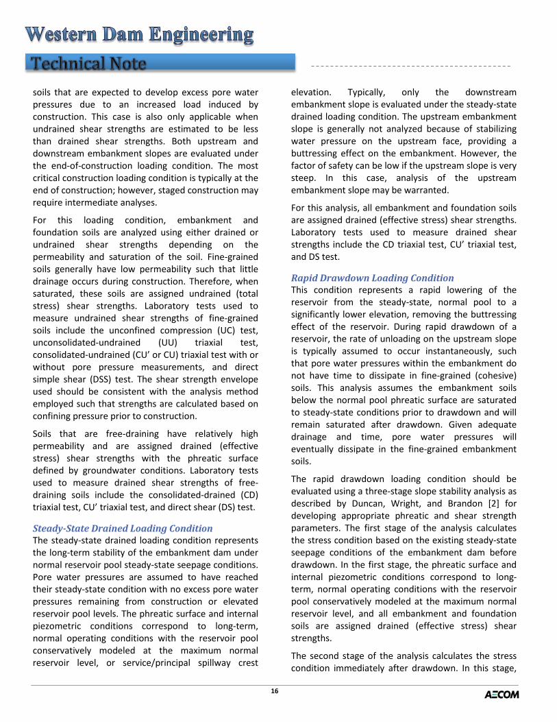
End-of-Construction Loading Condition The end-of-construction loading condition evaluates the stability of an embankment dam during and at the end of construction. Construction may include the initial construction of a dam or additional construction resulting from dam modifications. This loading case often controls the design of new, or significant enlargements, of embankments; especially those founded on soft clays. This loading condition should be analyzed for embankment dams consisting of fine-grained (cohesive) embankment and/or foundation
16
soils that are expected to develop excess pore water pressures due to an increased load induced by construction. This case is also only applicable when undrained shear strengths are estimated to be less than drained shear strengths. Both upstream and downstream embankment slopes are evaluated under the end-of-construction loading condition. The most critical construction loading condition is typically at the end of construction; however, staged construction may require intermediate analyses.
For this loading condition, embankment and foundation soils are analyzed using either drained or undrained shear strengths depending on the permeability and saturation of the soil. Fine-grained soils generally have low permeability such that little drainage occurs during construction. Therefore, when saturated, these soils are assigned undrained (total stress) shear strengths. Laboratory tests used to measure undrained shear strengths of fine-grained soils include the unconfined compression (UC) test, unconsolidated-undrained (UU) triaxial test, consolidated-undrained (CU’ or CU) triaxial test with or without pore pressure measurements, and direct simple shear (DSS) test. The shear strength envelope used should be consistent with the analysis method employed such that strengths are calculated based on confining pressure prior to construction.
Soils that are free-draining have relatively high permeability and are assigned drained (effective stress) shear strengths with the phreatic surface defined by groundwater conditions. Laboratory tests used to measure drained shear strengths of free-draining soils include the consolidated-drained (CD) triaxial test, CU’ triaxial test, and direct shear (DS) test.
Steady-State Drained Loading Condition The steady-state drained loading condition represents the long-term stability of the embankment dam under normal reservoir pool steady-state seepage conditions. Pore water pressures are assumed to have reached their steady-state condition with no excess pore water pressures remaining from construction or elevated reservoir pool levels. The phreatic surface and internal piezometric conditions correspond to long-term, normal operating conditions with the reservoir pool conservatively modeled at the maximum normal reservoir level, or service/principal spillway crest
elevation. Typically, only the downstream embankment slope is evaluated under the steady-state drained loading condition. The upstream embankment slope is generally not analyzed because of stabilizing water pressure on the upstream face, providing a buttressing effect on the embankment. However, the factor of safety can be low if the upstream slope is very steep. In this case, analysis of the upstream embankment slope may be warranted.
For this analysis, all embankment and foundation soils are assigned drained (effective stress) shear strengths. Laboratory tests used to measure drained shear strengths include the CD triaxial test, CU’ triaxial test, and DS test.
Rapid Drawdown Loading Condition This condition represents a rapid lowering of the reservoir from the steady-state, normal pool to a significantly lower elevation, removing the buttressing effect of the reservoir. During rapid drawdown of a reservoir, the rate of unloading on the upstream slope is typically assumed to occur instantaneously, such that pore water pressures within the embankment do not have time to dissipate in fine-grained (cohesive) soils. This analysis assumes the embankment soils below the normal pool phreatic surface are saturated to steady-state conditions prior to drawdown and will remain saturated after drawdown. Given adequate drainage and time, pore water pressures will eventually dissipate in the fine-grained embankment soils.
The rapid drawdown loading condition should be evaluated using a three-stage slope stability analysis as described by Duncan, Wright, and Brandon [2] for developing appropriate phreatic and shear strength parameters. The first stage of the analysis calculates the stress condition based on the existing steady-state seepage conditions of the embankment dam before drawdown. In the first stage, the phreatic surface and internal piezometric conditions correspond to long-term, normal operating conditions with the reservoir pool conservatively modeled at the maximum normal reservoir level, and all embankment and foundation soils are assigned drained (effective stress) shear strengths.
The second stage of the analysis calculates the stress condition immediately after drawdown. In this stage,

17
the phreatic surface is modeled at the lowest outlet elevation, and all soils that cannot drain as the reservoir is lowered are assigned undrained (total stress) shear strengths based on the effective stresses before drawdown, as calculated in the first stage. Coarser, free-draining soils having a permeability typically greater than 10-3 centimeters per second are assigned drained shear strengths based on the effective stress after drawdown [2].
In the third stage of the analysis, the rapid drawdown stability factor of safety is calculated using the lower of either the first-stage undrained or second-stage drained shear strength. Rapid drawdown is one of the more complex stability analyses and the analyst should consult relevant references such as [2], [3], and [4] for further details.
The most common laboratory test used to measure shear strengths for the rapid drawdown loading condition is the CU’ triaxial test, because this test can measure both undrained (total stress) and drained (effective stress) shear strengths. Other laboratory tests used to measure drained shear strengths include the CD triaxial test and DS test. Other laboratory tests used to measure undrained shear strengths include the UC test, UU triaxial test, CU triaxial test, and DSS test.
Shear Strength Characterization After the loading conditions for which an embankment dam should be analyzed are identified, appropriate shear strength parameters must be developed for the embankment and foundation soils under each applicable loading condition. Characterizing the shear strength of soils is dependent on both the type of soil and whether the soil behaves as undrained or drained under a particular loading condition. Provided below is a description of the shear strengths typically evaluated for coarse-grained, cohesionless soils (sands and gravels) and fine-grained, cohesive soils (clays and silts), including the corresponding laboratory and field testing to measure strengths and empirical correlations to estimate strengths.
Coarse-Grained Soils (Sands and Gravels) Coarse-grained, or granular, soils (sands and gravels) are typically free-draining and defined by drained shear strengths, except for very rapid loading (e.g., seismic loading, which is not addressed in this article).
These soils are similar in strength characterization since they have high permeabilities and sufficient drainage capacity to prevent pore water pressures from changing under most loadings.
Characterizing the drained shear strength of coarse-grained soils involves evaluating or estimating the effective stress friction angle (φ’). The Mohr-Coulomb strength envelope for granular soils goes through the origin of stress, as illustrated in Figure 1, and thus the effective stress cohesion (c’) is zero. Coarse-grained soils are therefore also often referred to as cohesionless soils. Although the effective stress cohesion is zero, the strength envelope for denser soils is often curved, as illustrated in Figure 1. For mathematical simplicity, an analyst may approximate the strength envelope as linear over the normal stress range of interest for the analysis, which may result in an “apparent” effective stress cohesion, as illustrated in Figure 2. It is important to understand that this is a mathematical convenience, and not a true property of the soil.
Figure 1: Mohr-Coulomb strength envelope for coarse-grained soils
Effective stress – σ’
Shea
r str
ess -
τ
φ’
c’
Linear Approximation of Shear Strength for stress range of interest
Shear Failure Envelope (Curved)
Figure 2: Curved shear strength envelope with linear interpretation and apparent cohesion, c’

18
One can see that the lower the effective stress, as in low-height dams or shallow failure surfaces, the “apparent” cohesion intercepts should be very small. Using high cohesion in low-height dams is rarely justifiable, is very influential to the analysis results, and results in higher calculated factors of safety that are not defendable. A non-linear envelop may be more appropriate in these cases.
Typical factors affecting values of φ’ for coarse-grained soils include density, confining pressure, angularity, and gradation. Values of φ’ increase as density increases, confining pressures decrease, particle angularity increases, and the soil gradation becomes broader (a wider range of particle sizes are included).
Laboratory tests used to measure values of φ’ for coarse-grained soils include the CD or CU’ triaxial shear test and the DS test (this test is best suited for finer-grained sands). It is difficult, however, to obtain undisturbed granular samples in the field or reconstitute the structure of natural deposits. Laboratory tests are often used to estimate φ’ for coarse-grained soils that will be placed during construction, such as embankment soils. Results from the laboratory tests should be checked against expected values based on gradation, relative density, and/or blow count in an effort to identify any obvious anomaly(ies). The presence of large particles (e.g., scalped samples or rockfill) may make laboratory test results misleading or impractical, and therefore not often warranted.
Results of field tests including the Standard Penetration Test (SPT), Cone Penetrometer Test (CPT), and shear wave velocity measurements are more commonly used to estimate values of φ’ for in-place, coarse-grained soils through the application of empirical correlations. Values of φ’ for in-place coarse-grained soils can also be estimated using empirical correlations to relative density and confining pressure, which are easier to measure directly than shear strength. A few of the more common strength correlations are presented below. These correlations, including others, are further described in reference [2], which is one of the more comprehensive references for shear strength characterization.
Figures 3 and 4 relate values of φ’ to overburden pressure and SPT blow count and CPT cone resistance, respectively. Relationships between φ’, relative density, and SPT blow count or CPT cone resistance are summarized in Tables 1 and 2. While these tables are easy to use, they do not take into account the effect of confining pressure. Indirect correlations to relative density through SPT blow count or CPT cone resistance and overburden stress are shown in Figures 5 and 6.
Figure 3: Relationship among SPT blow count, overburden pressure, and ’ for sands
Reference: Duncan, Wright, and Brandon (2014)

19
Figure 4: Relationship between CPT cone resistance, overburden pressure, and φ’ for sands
Table 1: Relationship among Relative Density, SPT Blow Count, and Angle of Internal Friction for Clean Sands
Table 2: Correlation among Relative Density, CPT Cone Resistance, and Angle of Internal Friction for Clean Sands
Figure 5: Relationship among SPT blow count, overburden pressure, and relative density for sands
Reference: Duncan, Wright, and Brandon (2014)
Reference: Duncan, Wright, and Brandon (2014)
Reference: Duncan, Wright, and Brandon (2014)
Reference: Duncan, Wright, and Brandon (2014)

20
Figure 6: Relationship among CPT cone resistance, overburden pressure, and relative density for sands
The drained shear strength of coarse-grained soils is strongly affected by relative density. Values of φ’ corresponding to confining pressures of about 1 atmosphere are related to relative density for sands in Figure 7.
Figure 7: Correlation between friction angle and relative density for sands
Fine-Grained Soils (Clays and Silts)
Fine-grained soils (clays and silts) are generally defined by undrained shear strengths for short-term loading conditions and drained shear strengths for long-term loading conditions. These soils generally have low permeabilities and can develop excess pore water pressures during some static loading conditions. Given adequate drainage and time, pore water pressures will eventually dissipate in fine-grained soils.
Clays Characterizations of shear strengths of clays are complex and the characterizations can be quite different for the different loading conditions, as discussed above. The drained shear strength of clays can be expressed in terms of effective stress (c’, φ’) strength parameters. The undrained shear strength can be expressed in terms of total stress (c, φ) strength parameters or in terms of undrained strength, Su. Further, there are different forms of characterization that can be used for Su – for example, constant Su, Su as a function of effective confining stress, and Su as a function of depth.
The overconsolidation ratio (OCR) of clays also has an impact on strength and is defined as the ratio of the maximum preconsolidation pressure of a soil mass to the current consolidation pressure the soil mass experiences. For normally consolidated to lightly overconsolidated clays, both undrained and drained shear strengths are of interest. When normally consolidated to lightly overconsolidated clays are loaded in shear, they tend to compress and generate positive pore water pressures, thereby resulting in an undrained shear strength that is generally less than the drained shear strength. Hence, the lower undrained shear strength must be used when analyzing undrained loading conditions. In contrast, for heavily overconsolidated, or compacted, clays, drained shear strengths are of most interest because these clays tend to expand when loaded in shear, and therefore, generate negative pore water pressures. The negative pore water pressures result in an undrained shear strength that is generally greater than the drained shear strength. As discussed previously with respect to rapid drawdown analyses, higher strengths resulting from negative pore water pressures are not normally
Reference: Duncan, Wright, and Brandon (2014)
Reference: Duncan, Wright, and Brandon (2014)

21
used in stability analyses because the negative pore water pressures cannot be relied upon in the field.
Typical drained Mohr-Coulomb failure envelopes for clays are presented in Figure 8. For normally consolidated clays, the Mohr-Coulomb strength envelope goes through the origin of stress and the effective stress cohesion (c’) is equal to zero. For overconsolidated clays, the Mohr-Coulomb strength envelope is generally curved in the low stress range, but still goes through the origin such that the effective stress cohesion is equal to zero. Similar to coarse-grained soils, an analyst may approximate the strength envelope as linear over the normal stress range of interest for the analysis, which may result in an “apparent” effective stress cohesion. Again, strength envelopes with intercepts (shown in Figure 8) are a mathematical convenience.
Figure 8: Mohr-Coulomb strength envelope for clays.
Stiff-fissured clays that are heavily overconsolidated should be carefully characterized. The undisturbed peak shear strength is generally not used to evaluate the stability of slopes composed of these soils. Shear strengths that can be mobilized in the field are generally less than in the laboratory since more softening and swelling occurs in these soils over long periods of time. Therefore, fully softened and/or residual shear strengths are generally more appropriate. If you are dealing with fissured clays, reference [2] should be consulted for its thorough discussion on that topic.
Other factors affecting clay strengths include anisotropy and strain rate. The undrained shear strength of clays varies with the orientation of the
principal stresses at failure and with the orientation of the failure plane. Isotropically consolidated soils generally yield higher shear strength than anisotropically consolidated soils where the vertical stress is higher than the horizontal. Common laboratory tests (i.e., CU) typically use isotropic consolidation, yet it should be recognized that soils in the field often exhibit anisotropic stress conditions. Furthermore, undrained shear strengths evaluated through laboratory testing can sometimes be overestimated due to the higher strain rates used to fail the specimen compared to those in the field. Figure 9 shows the undrained shear strength of saturated clay increases with increase in strain rate.
Figure 9: Effect of strain rate on undrained shear strength of clay.
Laboratory tests used to measure the undrained shear strength (c, φ or Su) of clays include the UC test (Su); UU, CU, CU’ triaxial shear test (c, φ or Su); and the DSS test (Su). Sample disturbance can reduce the undrained shear strength measured in laboratory tests. This effect may be reduced if the sample is consolidated to the same confining pressure it was consolidated to in the field. The SHANSEP (Stress History and Normalized Soil Engineering Properties) method can also compensate for sample disturbance and is a common approach used to estimate the undrained shear strength of clays. As described by Ladd and Foot (1974) and Ladd et al. (1977), the method involves consolidating clay samples to effective stresses that are greater than the in-situ stresses and interpreting
Reference: Mitchell and Soga (2005)

22
measured strengths in terms of an undrained shear strength ratio, Su/σ’v. Shear strength ratios increase with higher OCRs; meaning overconsolidated clays have higher shear strength than normally consolidated. See reference [2] for further discussion.
A field test used for direct measurement of the undrained shear strength (Su) of clays is the vane shear test, which has been successfully used for measuring the undrained shear strength of soft to medium stiff clays. Limitations are that the test can be affected by sand lenses and seams and the raw undrained shear strength measured from the test requires an empirical correction factor that varies with plasticity index and accounts for anisotropy and strain rate effects. The data on which the correction factor is based are widely scattered and therefore vane strengths should not be viewed as precise. The pocket penetrometer test and torvane test can be used to obtain very quick, approximate measurements of undrained shear strength in the field or laboratory. However, the pocket penetrometer and torvane tests are relatively crude and should be considered as only rough indications of shear strength.
The laboratory test most commonly used to measure the drained shear strength (c’, φ‘) of clays is the CU’ triaxial shear test. The CU’ test is more practical than the CD test because the strain rates required for a CD test are typically extremely slow, requiring an impractically long test time. In addition, the CU’ test can be used to obtain both undrained (total stress) and drained (effective stress) shear strength parameters. However, the CD triaxial test and DS test can also be used, if the long test times can be accommodated. For stiff-fissured clays, laboratory tests are performed on remolded specimens to evaluate fully softened and/or residual drained shear strengths. The DS test is commonly used to measure the fully softened shear strength of stiff-fissured clays. Torsional ring shear tests are most suitable for estimating the residual shear strength of stiff-fissured clays since the test can measure shear stresses over any magnitude of displacement through continuous rotation.
Laboratory tests provide the best strength data for clays, and reasonably undisturbed samples of these materials can typically be obtained. However, various empirical correlations developed to estimate strengths
for clays may be sufficient in some cases. It is recommended these methods and correlations be used with caution, since the behavior, and hence strength characterization, for clays is typically more complex than for granular soils. A few of the more common shear strength correlations are presented below. These correlations, and others, are further described in reference [2]. It may also be useful to use these correlations as a check to validate the results of laboratory tests.
Results of field tests including the SPT, CPT, and shear wave velocity measurements can be used for estimating the undrained shear strength (Su) of clays through the application of empirical correlations. SPT blow counts (N) in clay can be used to roughly estimate the variation of Su/N with plasticity index, as shown in Figure 10. Su can also be estimated from CPT cone resistance using the following relationship:
𝑆𝑢 =𝑞𝑐 − 𝜎𝑣𝑣𝑁𝑘∗
Where: 𝑞𝑐 = cone tip resistance, 𝜎𝑣𝑣 = total overburden pressure at test depth, 𝑁𝑘∗ = cone factor
The variation of 𝑁𝑘∗ with plasticity index for a variety of clays is shown in Figure 11. An 𝑁𝑘∗ value of 14 is typically applied to clays for any value of plasticity index.
Reference: Duncan, Wright, and Brandon (2014)
Figure 10: Variation of the ratio of undrained shear strength (Su) divided by SPT blow count

23
Figure 11: Variation of the cone factor (𝑵𝒌∗ ) with plasticity index
for clays
Drained shear strength parameters (c’, φ’) for clays vary depending on consolidation of the clay. As shown previously in Figure 8, the Mohr-Coulomb strength envelope for normally consolidated clays goes through the origin of stress and the effective stress cohesion (c’) is equal to zero. Typical values of peak effective stress friction angle (φ’) for normally consolidated clays are provided in Table 3. For overconsolidated clays, the Mohr-Coulomb strength envelope is generally curved in the low stress range and approximated as linear over the normal stress range of interest for the analysis, which may result in an “apparent” effective stress cohesion (c’). Typical peak values of φ’ and c’ for compacted clays corresponding to a relative compaction of 100 percent of the Standard Proctor maximum dry density are given in Table 4.
Table 3: Typical Values of Peak Friction Angle (φ’) for Normally Consolidated Claysa
Table 4: Typical Peak Drained Strengths for Compacted Cohesive Soils
Silts Silts have an interesting soil particle composition, as they can behave similarly to either fine sands or clays. When the term fine-grained is used, it almost always includes silts in this category. But silts themselves can be divided into two general categories, non-plastic and plastic. Non-plastic silts behave more like fine sands, while plastic silts behave more like clays. Evaluating whether a unit of silt is non-plastic or plastic can be achieved using the Atterberg Limit laboratory test (refer to “Soil Characterization (Part 1) – Here’s the Dirt”).
Since silts can have a wide range of permeabilities, it can be difficult to predict if these soils will behave as drained or undrained under various loading conditions.
Reference: Duncan, Wright, and Brandon (2014)
Reference: Duncan, Wright, and Brandon (2014)
Reference: Duncan, Wright, and Brandon (2014)

24
It is common to characterize silts using both drained and undrained shear strengths similar to clays. For drained conditions, the shear strength of silt can be characterized by an effective stress friction angle (φ’) with an assumed effective stress cohesion (c’) equal to zero. For undrained conditions, the shear strength of silts can be expressed using total stress strength parameters (c, φ) or in terms of undrained strength, Su. Similar to clays, there are different forms of characterization that can be used for Su – for example, constant Su, Su as a function of effective confining stress, and Su as a function of depth.
Laboratory tests used to measure values of φ’ for silts include the CD or CU’ triaxial shear test and the DS test. Laboratory tests used to measure the undrained shear strength (c, φ or Su) of silts include the UC test (Su), UU or CU/CU’ triaxial shear test (c, φ or Su), or the DSS test (Su). Similar to coarse-grained soils, it can be difficult to obtain quality undisturbed samples of silts in the field, particularly non-plastic or very low plasticity silts.
Strength behaviors of silts have not been as widely studied as those of sands or clays. As a result of this general lack of research and compilation of data, very few empirical correlations exist for predicting shear strength values for silts. Empirical strength correlations that are available for silts are often regionally specific and developed with relatively limited data sets. Similar to sands and clays, SPT, CPT, and shear wave field tests can be used for empirical strength correlations of silts. Empirical correlations using results of field tests for sands can generally be applied to estimate shear strengths of non-plastic silts. Shear strengths of plastic silts can generally be estimated from empirical correlations using results of field tests for clays. It would be prudent to incorporate a level of conservatism when using correlations for silts. Shear Strengths by Federal Agency Various government agencies have identified shear strength envelopes to be used for design loading conditions. Therefore, stability analyses performed for these agencies should utilize their specific strength characterization criteria. Reference [1] provides a useful summary of then current guidance provided by various federal agencies such as: United States Army Corps of Engineers; Bureau of Reclamation; United
States Department of Agriculture, National Resources Conservation Service; and Federal Energy Regulatory Commission. Guidance documents for each agency should be referenced for any updates.
Conclusion Slope stability analyses of embankment dams are highly dependent on shear strength parameters assigned to the embankment and foundation soils. It is therefore very important to perform a detailed shear strength characterization of the various soils to obtain meaningful slope stability results. Shear strength characterization requires both knowledge and experience to select and develop appropriate parameters for various embankment and foundation soils. Shear strengths of soils vary depending on the loading conditions needing to be analyzed, and the variations have a significant impact on slope stability calculations. Careful shear strength characterization is therefore an imperative, in most cases the most important, component of slope stability analyses for embankment dams.
Useful References [1] Strength of Materials for Embankment Dams, United States Society on
Dams, February 2007. [2] Soil Strength and Slope Stability, J. Michael Duncan, Stephen G.
Wright, and Thomas L. Brandon, 2nd Edition, 2014. [3] Slope Stability during Rapid Drawdown, James M. Duncan, Stephen G.
Wright, and Kai S. Wong, 1992. [4] Rapid Drawdown Analysis – What is An Analyst to Do? John W. France
and Christina J.C. Winckler, 2013. [5] Fundamentals of Soil Behavior, James K. Mitchell and Kenichi Soga, 3rd
Edition, 2005. [6] Engineering Field Manual, Chapter 4 - Elementary Soil Engineering,
U.S. Department of Agriculture, Natural Resources Conservation Service (NRCS), July 1984 (Fourth Printing)
[7] Earth Manual, Part 1, U.S. Department of the Interior, Bureau of Reclamation, 1998 (Third Edition)
[8] EM 1110-1-1804, Geotechnical Investigations, U.S. Army Corps of Engineers, January 2001
[9] EM 1110-1-1802, Geophysical Exploration for Engineering and Environmental Investigations, Department of the Army, U.S. Army Corps of Engineers, 31 August 1995
[10] FHWA NHI-06-088, Soils and Foundations, Reference Manual – Volume 1, U.S. Department of Transportation, Federal Highway Administration, December 2006
[11] Manual on Estimating Soil Properties for Foundation Design, EPRI EL-6800, Electric Power Research Institute (EPRI), August 1990.
[12] New design procedure for stability of soft clays, Ladd, CC. and Foot, R. (1974). ASCE Journal of the Geotechnical Engineering Division. Vol 100, No GT7, pp 763-786.
[13] Stress-deformation and strength characteristics. Ladd, CC, Foot, R, Ishihara, K, Schlosser, F and Poulos, HG. (1977).International conference on soil mechanics and foundation engineering, 9, Proceedings, Vol. 2, pp 421- 494. Tokyo.