A PVSS Application for Monitoring the Start-up of the Super...
120
A PVSS Application for Monitoring the Start-up of the Super Proton Synchrotron After Major Breakdowns Diplomarbeit zur Erlangung des akademischen Grades Diplom-Ingenieur (Fachhochschule) Eingereicht von Jan Stowisek Betreuer: Dr. Luigi Scibile, CERN Begutachter: FH-Prof. Dipl.-Ing. Karin Pröll, FHS Hagenberg August 2001
Transcript of A PVSS Application for Monitoring the Start-up of the Super...

)DFKKRFKVFKXO�6WXGLHQJDQJ62)7:$5(�(1*,1((5,1*$������+DJHQEHUJ��$XVWULD
A PVSS Application for Monitoringthe Start-up of the Super Proton Synchrotron
After Major Breakdowns
Diplomarbeit
zur Erlangung des akademischen GradesDiplom-Ingenieur (Fachhochschule)
Eingereicht von
Jan Stowisek
Betreuer: Dr. Luigi Scibile, CERNBegutachter: FH-Prof. Dipl.-Ing. Karin Pröll, FHS Hagenberg
August 2001

- i -
EIDESSTATTLICHE ERKLÄRUNG
Ich erkläre hiermit an Eides statt, dass ich die vorliegende Arbeit selbständig und ohne fremdeHilfe verfasst, keine anderen als die angegebenen Quellen und Hilfsmittel benutzt, mich auchsonst keiner unerlaubten Hilfe bedient habe und diese Diplomarbeit bisher weder im In- nochim Ausland in irgendeiner Form als Prüfungsarbeit vorgelegt habe.
Ort, Datum Unterschrift
- ii -
KURZFASSUNGSupervisory Control and Data Acquisition Systeme (SCADA-Systeme) werden heuteweitreichend für die Überwachung und Steuerung technischer Anlagen der EuropäischenKernforschungsorganisation (CERN) eingesetzt. Eine Vielzahl verschiedener SCADA-Systeme dienen dabei der Überwachung elektrischer, kryogenischer und anderer Systeme,sowie der Steuerung und Kontrolle von Teilchenbeschleunigern und physikalischenExperimenten.
Diese Diplomarbeit behandelt die Entwicklung einer auf SCADA-Technologie basierendenSoftwareapplikation für zwei der zentralen Kontrollräume des CERN. Zweck der Anwendungist die Überwachung des Super Proton Synchrotron (SPS), dem zweitgrößtenTeilchenbeschleuniger des Labors, während seines Neustarts nach schweren Pannen. EinerCERN-Empfehlung Folge leistend, basiert die Anwendung auf PVSS II, einemkommerziellen SCADA-Produkt, das die derzeit im Einsatz befindliche heterogeneKomponentenarchitektur zur Supervision von SPS-Equipment ablösen soll.
Die Installation des SCADA-Produktes als redundantes und verteiltes System, mit dem Zielmaximale Verfügbarkeit und Datenaustausch mit anderen PVSS Systemen zu garantieren, isteiner der Kernpunkte dieser Arbeit. Um mit SPS-Hardware zur Laufzeit kommunizieren zukönnen, musste ein PVSS Treiber entwickelt werden, der unter Zuhilfenahme einerexistierenden Middleware den Datenaustausch mit verschiedenartigen Geräten rund um denTeilchenbeschleuniger ermöglicht. Das objektorientierte Design und die C++-Implementierung dieses Treibers werden im Detail diskutiert. Besonderes Augenmerk wurdeauch auf die Implementierung der Benutzerschnittstelle der Anwendung gelegt, jenen Teil desSystems mit dem Operatoren auf täglicher Basis arbeiten werden. Ein erster Prototyp derBenutzerschnittstelle, bestehend aus einigen PVSS Panels, wurde in enger Zusammenarbeitmit den betreffenden Kontrollraum-Operatoren entwickelt. Die Ergebnisse dieserZusammenarbeit werden im Rahmen dieser Diplomarbeit präsentiert. Zusätzlich zurApplikation selbst musste ein off-line Datenbanksystem zur Verwaltung statischer PVSSKonfigurationsinformationen entwickelt werden. Der Entwurf einer Integrationsstrategie fürexistierende Konfigurationsdaten, das Design einer relationalen Datenbankstruktur zurSpeicherung dieser Informationen und die Implementierung von Perl Scripts und PL/SQLProzeduren zum Datenimport und –export werden in dieser Arbeit präsentiert.

- iii -
ABSTRACTSupervisory Control and Data Acquisition (SCADA) systems are widely employed inmonitoring and controlling technical facilities at the European Organization for NuclearResearch (CERN). Various kinds of SCADA systems are used for the supervision ofelectricity, cooling, cryogenics and other systems as wells as for the control of thelaboratory’s particle accelerators and high-energy physics (HEP) experiments.
This thesis is concerned with the development of a software application for two of CERN’smain control rooms, for monitoring the start-up of the Super Proton Synchrotron (SPS), thelaboratory’s second largest particle accelerator. Following a CERN recommendation, theapplication is based on PVSS II, a commercial off-the-shell SCADA product that will replacethe heterogeneous component architecture currently used for monitoring SPS equipment.
The set-up of the SCADA system in a redundant, distributed and scattered manner in order toguarantee high dependability and the possibility of doing data exchange with external PVSSII systems is a central issue of this work. A PVSS Driver Manager to SL-Equip, a middlewareallowing data exchange with heterogeneous remote devices located around the accelerator, isdeveloped in order to communicate with SPS hardware. The object-oriented design and theC++ implementation of this driver are discussed in a detailed manner. Special attention is paidto the design and implementation of the application’s user interface, for this is the part of thesystem that the control rooms’ operators will be confronted with on a daily basis. A firstprototype of this interface, consisting of a series of PVSS panels, is developed in close co-operation with the operators concerned. In addition to the application itself, an off-linedatabase system for managing static PVSS configuration information is created. Anintegration strategy for existing configuration data is developed, a relational databasestructure for storing the information is designed and Perl scripts and PL/SQL procedures fordata import and export are implemented.

- iv -
THANKS AND ACKNOWLEDGEMENTSI would like to thank my supervisor at CERN, Luigi Scibile, for sacrificing a lot of his timecorrecting this thesis as well as for the many insightful discussions we had during myinternship at CERN.
I gratefully acknowledge the support of Peter Sollander and Robin Martini, two colleagues inthe ST/MO group who contributed a lot to this work. Peter’s profound knowledge of thesystems involved in the SPS start-up and Robin’s expertise in database engineering have beena great help.
Of course, I want to thank Karin Pröll, my supervisor from the Polytechnic University ofHagenberg for her support during my internship at CERN and while I was writing this thesis.
I also want to express my thanks to Gregory Curtis, my English teacher at the Upper AustrianPolytechnic University, who sacrificed his time to correct this work and to improve mysometimes modest style in English.
Especially, I want to thank Johannes Dirnberger and Yann Bieber who helped me out withcountless suggestions during my stay at CERN.
This thesis is dedicated to my family.
Jan Stowisek, August 2001

- v -
TABLE OF CONTENTS
1. Introduction................................................................................................................. 9
1.1 Organizational Environment ............................................................................. 91.1.1 CERN – The European Organization for Nuclear Research...........................................91.1.2 The Technical Support / Monitoring and Operation Group..........................................10
1.2 Motivation for the Project................................................................................ 10
1.3 Objectives ......................................................................................................... 11
1.4 Project Proceeding ........................................................................................... 121.4.1 Project Development Model .......................................................................................12
1.5 Overview of the Document............................................................................... 12
2. Basic Notions............................................................................................................. 14
2.1 Supervisory Control and Data Acquisition Systems ....................................... 142.1.1 Definition of SCADA-Related Terms .........................................................................142.1.2 General Architecture of SCADA Systems...................................................................15
2.1.2.1 Client Layer......................................................................................................162.1.2.2 Processing Layer...............................................................................................162.1.2.3 Data (Server) Layer...........................................................................................17
2.1.3 Features of SCADA Systems......................................................................................172.1.4 Benefits From the Use of SCADA..............................................................................182.1.5 Limitations of SCADA Technology............................................................................18
2.1.6 Outlook to the Future .................................................................................................19
2.2 PVSS II – An Example of an Industry SCADA System.................................. 192.2.1 Product Description....................................................................................................19
2.2.2 The Data Point Concept .............................................................................................202.2.3 PVSS System Architecture – The Manager Concept ...................................................20
2.2.3.1 Event Manager (EM) ........................................................................................21
2.2.3.2 Database Manager (DM) ...................................................................................212.2.3.3 Control Manager (CM) .....................................................................................222.2.3.4 Driver Managers (Drv)......................................................................................22
2.2.3.5 User Interface Manager (UIM) ..........................................................................222.2.3.6 Other Managers ................................................................................................23
2.2.4 Scattered and Distributed PVSS Systems ....................................................................23
2.2.4.1 Scattered Systems .............................................................................................232.2.4.2 Distributed Systems ..........................................................................................24
2.2.5 The PVSS Redundancy Concept.................................................................................24
2.3 The SL-Equip Package..................................................................................... 252.3.1 System Architecture...................................................................................................252.3.2 Equipment Naming Conventions ................................................................................27
2.3.3 SL-Equip Client Calls ................................................................................................28
2.4 The Super Proton Synchrotron........................................................................ 28
3. Problem Description .................................................................................................. 30
3.1 Overview of the Problem.................................................................................. 30
- vi -
3.2 Parts of the Problem – Scope of the Project .................................................... 303.2.1 Set-up and Configuration of the PVSS System............................................................30
3.2.1.1 Design for High Dependability..........................................................................303.2.1.2 Design for Data Exchange.................................................................................30
3.2.1.3 Implementation Constraints...............................................................................313.2.2 Implementation of a PVSS Driver to SL-Equip...........................................................313.2.3 Implementation of a Data Loader for Automatic Data Point Generation ......................31
3.2.4 Mimic Diagrams for the SPS Restart Application .......................................................32
4. System Design............................................................................................................ 33
4.1 System Architecture......................................................................................... 344.1.1 Redundant PVSS System............................................................................................344.1.2 Data Exchange...........................................................................................................354.1.3 Data Acquisition ........................................................................................................35
4.1.4 PVSS Core System.....................................................................................................364.1.5 PVSS User Interface ..................................................................................................36
4.2 Driver to SL-EQUIP ........................................................................................ 364.2.1 General PVSS Driver Concept....................................................................................364.2.2 Specification of the Address Mapping ........................................................................384.2.3 Class Design ..............................................................................................................40
4.2.3.1 Core Classes .....................................................................................................414.2.3.2 Transformation Classes .....................................................................................444.2.3.3 Utility Classes...................................................................................................46
4.2.4 Object Design ............................................................................................................464.2.4.1 Initialisation......................................................................................................474.2.4.2 Hardware Activity.............................................................................................48
4.2.4.3 Termination ......................................................................................................49
4.3 Static Data Definition in an Off-line Database ................................................ 494.3.1 Database Design ........................................................................................................49
4.3.1.1 General Design Rules........................................................................................494.3.1.2 TDRefDB Table Structure.................................................................................504.3.1.3 TDRefDB User Views ......................................................................................56
4.3.2 Data Import in the TDRefDB .....................................................................................584.3.2.1 Overview of the Data Import Strategy ...............................................................584.3.2.2 Import of TDS Configuration Data ....................................................................59
4.3.2.3 Import of SL-Equip Configuration Data ............................................................614.3.3 Data Export From the TDRefDB to ASCII Manager File Format ................................63
4.3.3.1 Analysis of the ASCII Manager File Format ......................................................63
4.3.3.2 Specification of the Data Extraction Script ........................................................65
4.4 Mimic Diagrams............................................................................................... 65
5. Implementation.......................................................................................................... 68
5.1 System Architecture......................................................................................... 685.1.1 Set-up of the Redundant Linux Servers.......................................................................69
5.1.1.1 Additional Hardware Installation.......................................................................69
5.1.1.2 Software Installation .........................................................................................695.1.1.3 Software Configuration .....................................................................................69
5.1.2 Set-up of the Windows NT Workstations....................................................................69

- vii -
5.1.2.1 Software Installation .........................................................................................70
5.1.2.2 Software Configuration .....................................................................................70
5.2 Driver Implementation..................................................................................... 705.2.1 Implementation Constraints........................................................................................70
5.2.2 Implementation of the Classes ....................................................................................705.2.2.1 SleDriver ..........................................................................................................705.2.2.2 SleResources.....................................................................................................71
5.2.2.3 SleMapper ........................................................................................................725.2.2.4 SleMapObj........................................................................................................745.2.2.5 SleSrvHdl .........................................................................................................74
5.2.2.6 SleTransXXX ...................................................................................................755.2.3 Implementation of the Driver Configuration Panel ......................................................76
5.3 Implementation of the Static Configuration Database.................................... 775.3.1 TDRefDB Database Structure.....................................................................................78
5.3.1.1 TDRefDB Tables ..............................................................................................785.3.1.2 TDRefDB User Views ......................................................................................78
5.3.2 Import of Existing Configuration Information in the TDRefDB...................................795.3.2.1 Implementation of PL/SQL Procedures for Importing TDS Configuration Data..795.3.2.2 Implementation of Perl Scripts for Importing SL-Equip Configuration Data.......83
5.3.3 Implementation of an SQL Script for Exporting PVSS Configuration Data .................85
5.4 Implementation of the User Interface.............................................................. 85
6. Validation and Verification ....................................................................................... 90
6.1 Component Tests.............................................................................................. 906.1.1 PVSS System Set-up ..................................................................................................906.1.2 SL-Equip Driver ........................................................................................................92
6.1.3 Static Configuration Database and Data Loaders.........................................................936.1.4 User Interface Panels..................................................................................................94
6.2 System Tests ..................................................................................................... 96
7. Conclusion................................................................................................................. 97
7.1 Goal and Solution............................................................................................. 97
7.2 Unsolved Problems........................................................................................... 98
7.3 Possible Extensions........................................................................................... 98
7.4 Concluding Remarks........................................................................................ 99
8. Table of Figures .......................................................................................................100
9. Table of Listings .......................................................................................................101
10. List of Tables ........................................................................................................102
11. References ............................................................................................................103
11.1 Literature ........................................................................................................103
11.2 Papers and Internal Reports...........................................................................103
11.3 Online Help......................................................................................................104
11.4 World Wide Web References..........................................................................104

- viii -
Appendix A. PVSS Server Configuration .....................................................................107
A.1 “SET_REDU” File on the Redundant PVSS Servers.....................................107
A.2 “config” File on the Redundant PVSS Servers...............................................107
A.3 “progs” File on the Redundant PVSS Servers ...............................................108
Appendix B. SL-Equip Driver (SleSrvHdl)...................................................................109
Appendix C. SL-Equip Data Import Scripts .................................................................112
Appendix D. Data Export: Data Loader Script .............................................................118
A PVSS Application for Monitoring the SPS Start-up Introduction
- 9 -
1. INTRODUCTIONThis thesis is concerned with the development of a software application for monitoring thestart-up of the Super Proton Synchrotron (SPS), CERN’s second largest particle accelerator.As the title suggests, PVSS, the CERN recommended supervisory control and data acquisition(SCADA) system, will serve as a basis for the application.
This first chapter provides the reader with some background information about theorganizational environment in which this thesis was written, roughly outlines the problem tobe solved, gives an overview of existing solutions to similar problems and, finally, presents anoutlook to the following chapters.
1.1 Organizational Environment
This section starts with a general presentation of the European Organization for NuclearResearch (CERN) and its activities, followed by a description of the author’s immediateworking environment, the Monitoring and Operation (ST/MO) group.
1.1.1 CERN – The European Organization for Nuclear Research
CERN, often referred to as the European Laboratory for Particle Physics but officially calledthe European Organization for Nuclear Research, is one of the largest and most importanthigh-energy physics (HEP) centres in the world. Established in 1954 with the aim to providefor European collaboration in nuclear research of a pure scientific and fundamental character,the institute nowadays attracts over 6,000 scientists of more than eighty nationalities.Following its mandate laid out in the CERN Convention, the organization “has no concernwith work for military requirements and the results of its experimental and theoretical workare published or otherwise made generally available” [CERN, 1954].
CERN is situated on the border between France and Switzerland, just outside Geneva, alocation that symbolises the international spirit of collaboration that is one of the reasons forthe laboratory's success. From the original 12 signatories of the CERN convention,membership has grown to the present 20 Member States.
CERN’s accelerator complex is the most versatile in the world, consisting of a set of tenlinear and circular machines. The first operating accelerator, the Synchro-Cyclotron, was builtin 1954, in parallel with the Proton Synchrotron (PS). The PS is today the backbone ofCERN's particle beam factory, feeding other accelerators with different types of particles. The1970s saw the construction of the Super Proton Synchrotron (SPS), at which Nobel-prizewinning work was done in the 1980s. The SPS continues to provide beams for experimentsand is also the final link in the chain of accelerators, providing beams for the 27 kilometrelong Large Electron-Positron Collider (LEP). CERN's next big machine, due to startoperating in 2005, is the Large Hadron Collider (LHC), at which the fascinating quest for theHiggs boson, the last undetected particle of the standard model, will be carried on.
For more comprehensive information about CERN, its accelerator complex, experiments andcontributions to the world of high-energy physics, please refer to [WWW-CERN].
A PVSS Application for Monitoring the SPS Start-up Introduction
- 10 -
1.1.2 The Technical Support / Monitoring and Operation Group
Seeing that CERN is hierarchically organised in divisions, groups and sections, we will take acloser look at the Monitoring and Operation (ST/MO) group, the subgroup of the TechnicalSupport (ST) division the author is working for.
Within the ST division, which has the mandate to provide technical support for acceleratorsand related experimental areas, including the LHC project, the ST/MO group is responsiblefor the monitoring and operation of all CERN technical infrastructure.
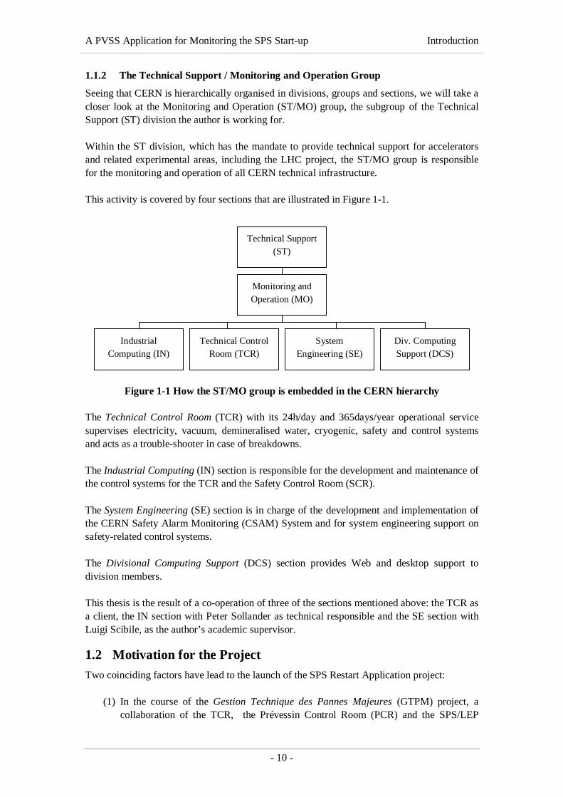
This activity is covered by four sections that are illustrated in Figure 1-1.
Figure 1-1 How the ST/MO group is embedded in the CERN hierarchy
The Technical Control Room (TCR) with its 24h/day and 365days/year operational servicesupervises electricity, vacuum, demineralised water, cryogenic, safety and control systemsand acts as a trouble-shooter in case of breakdowns.
The Industrial Computing (IN) section is responsible for the development and maintenance ofthe control systems for the TCR and the Safety Control Room (SCR).
The System Engineering (SE) section is in charge of the development and implementation ofthe CERN Safety Alarm Monitoring (CSAM) System and for system engineering support onsafety-related control systems.
The Divisional Computing Support (DCS) section provides Web and desktop support todivision members.
This thesis is the result of a co-operation of three of the sections mentioned above: the TCR asa client, the IN section with Peter Sollander as technical responsible and the SE section withLuigi Scibile, as the author’s academic supervisor.
1.2 Motivation for the Project
Two coinciding factors have lead to the launch of the SPS Restart Application project:
(1) In the course of the Gestion Technique des Pannes Majeures (GTPM) project, acollaboration of the TCR, the Prévessin Control Room (PCR) and the SPS/LEP
Technical Support(ST)
Monitoring andOperation (MO)
IndustrialComputing (IN)
Technical ControlRoom (TCR)
SystemEngineering (SE)
Div. ComputingSupport (DCS)

A PVSS Application for Monitoring the SPS Start-up Introduction
- 11 -
Controls (SL/CO) group, a thorough analysis of the functions and logic of the SPSstart-up procedure was performed. While the project’s main objective was to workout system diagrams, operating instructions and technical descriptions in order tofacilitate the restart of the SPS after a major breakdown, it was also decided todevelop an application for monitoring the systems involved in the start-up procedure.
(2) PVSS II, an industry SCADA system developed by the Austrian company ETM, waschosen as the CERN recommended SCADA system for all LHC experiments. As aconsequence, the ST/MO group determined to migrate its existing control systems,notably the Technical Data Server (TDS), to PVSS. The SPS Restart Applicationshould become the group’s first application to be implemented using PVSS in atechnical services context.
The SPS Restart Application project was launched as a subproject of GTPM, at the same timepursuing the objectives of the PVSS.TSI project. For more information about the twoprojects, please refer to [WWW-STMO].
1.3 Objectives
The goal of the project is the development of a software application for the CERN TechnicalControl Room (TCR) and the Prévessin Experiment Control Room (PCR). This softwareapplication shall allow the control rooms’ operators to remotely monitor the start-up of theSuper Proton Synchrotron (SPS) after major breakdowns.
The application shall be based on PVSS and its user interface shall consist of a series ofmimic diagrams, so-called PVSS panels, that display the current status of all systems involvedin the accelerator’s start-up, i.e. electricity, demineralised water, vacuum and other systems.
From a central view, consisting of some boxes displaying the system states on a very highlevel (one box per system), the operators shall be able to get more detailed information byclicking on the boxes and zooming in to the systems concerned. The user interface shall allowthe operators to localise defects, the cause of the defect will then be detected using existingtools.
In order to implement such an application, it is necessary to set up a SCADA system thatacquires data from existing equipment control systems, notably the Technical Data Server(TDS) and SL-Equip. PVSS II was chosen to fulfil this task. The PVSS system shall beconfigured in a redundant way in order to increase the system’s dependability. Furthermore,data exchange with other PVSS systems at CERN shall be possible. In order to acquire datafrom the control systems mentioned above, the implementation of a PVSS driver to SL-Equipis necessary. A driver to the TDS already exists and can be reused.
Finally, the PVSS system has to be configured in order to acquire data using the driversmentioned above. The configuration information required for this purpose is currently storedin:
• the Technical Data Reference Database (TDRefDB),• formatted ASCII text files and• paper files.

A PVSS Application for Monitoring the SPS Start-up Introduction
- 12 -
This configuration data shall first be converted into a homogenous format (introduced in adatabase) and then injected to the PVSS system at run-time.
1.4 Project Proceeding
This chapter deals with the project engineering aspects of the system development process.The development approach chosen is described as well as important project milestones(anchor points).
1.4.1 Project Development Model
As the SPS Restart Application was the first PVSS application developed within the ST/MOgroup, little experience on this subject was available. Consequently, a complete specificationof the project was difficult to establish from scratch and several iterations were necessary tocapture all user requirements. Initially, only four project anchor points were defined:
(1) the set-up and configuration of the PVSS system,(2) the implementation of the PVSS driver to SL-Equip,(3) the development of a data loader and(4) the development of the application’s user interface.
These four anchor points were treated as interdependent subprojects; each of them was dealtwith using an evolutionary prototyping approach. Prototyping means building a small versionof a system, usually with limited functionality, that can be used to help the user or customeridentify the key requirements of a system and demonstrate the feasibility of a design orapproach” ([Pfleeger, 1998]).
As opposed to a throw-away prototype that is not intended to be used as an actual part of thedelivered software, an evolutionary prototype is “developed to learn about a problem andform the basis for some or all of the delivered software” ([Pfleeger, 1998]).
Accordingly, as soon as a basic set of requirements was defined, a first prototype was builtand presented to the potential users. Based on their feedback, the requirements were refinedand further functionality was integrated in the prototype until a satisfactory solution wasfound.
1.5 Overview of the Document
This document contains the description of the SPS Restart Monitoring Application, which hasbeen developed and implemented for the Technical Control Room (TCR) at CERN in order toprovide an appropriate tool for monitoring the status of all systems involved during the start-up of the Super Proton Synchrotron.
The notation of this work is kept very simple. While textual descriptions and explanations ofmechanisms and functions are written in a serif font (Times New Roman), any source codeextracts as well as class, method and variable names etc. are written in fixed-pitch font(Courier New). Important names, key terms and central messages of a chapter areemphasised using an italic font.
Chapter 2 gives an overview of the technologies and techniques used in the course of the SPSRestart Application project. It serves as an introduction for readers who are not familiar with

A PVSS Application for Monitoring the SPS Start-up Introduction
- 13 -
SCADA systems in general and with PVSS II in particular. Furthermore, SL-Equip, anequipment control middleware implemented and used at CERN, is presented. Last but notleast, a presentation of the SPS, CERN’s second largest accelerator is given.
Chapter 3 provides an extensive description of the problem that triggered the launch of theSPS Restart Application project. After an outline of the general problem, the subtasks to besolved by the author are dealt with in detail.
Chapter 4 describes the proposed solution, particularly focusing on the system’s design. Thechapter follows the same structure as chapter 3, starting with an overview of the designedsystem and then dealing with its components one by one.
Chapter 5 describes the implementation of the system, explaining the major concepts used aswell as some interesting implementation details. Special emphasis will be put on theimplementation of the PVSS driver to SL-Equip and the off-line PVSS configurationdatabase.
Chapter 6 deals with validation and verification aspects and describes how the SPS RestartApplication was tested.
Chapter 7 contains a concise summary of the thesis and gives a brief overview of unsolvedproblems, possible extensions and potential weaknesses of the implemented solution.

A PVSS Application for Monitoring the SPS Start-up Basic Notions
- 14 -
2. BASIC NOTIONSThis chapter introduces the reader to the most important concepts and tools used in the courseof the project. First, a brief introduction to the concept of SCADA systems is provided,followed by a presentation of PVSS II as an example of an industry SCADA system. Finally,SL-Equip, the middleware that will provide equipment data for the SPS Restart application, isintroduced
2.1 Supervisory Control and Data Acquisition Systems
As this work is mainly concerned with SCADA systems, an introduction to this technology iscrucial for readers who are not yet familiar with it.
2.1.1 Definition of SCADA-Related Terms
First of all, we will define the term Supervisory Control and Data Acquisition (SCADA)according to our needs and try to point out the differences to similar concepts. Two of themost important characteristics of SCADA systems are already included in the acronym:
(1) the capability to collect data from some kind of installation and(2) the ability to control these facilities sending (limited) control instructions.
What is not mentioned, however, is that
(3) SCADA systems are typically used to supervise and control facilities in remotelocations.
Putting these three elements together, we define that SCADA is a “technology to collect datafrom one ore more distant facilities and/or send limited control instructions to those facilities”[Boyer, 1999].
Although SCADA systems limit the amount of control that can be exercised, they still doallow (supervisory) control. This is one of the points that distinguish SCADA from similarconcepts, such as telemetry: SCADA systems are two-way systems, allowing not only tomonitor what is going on at a remote location but also to do something about it.
As this thesis is exclusively concerned with the software aspects of SCADA technology, wewill refine our definition and describe SCADA systems as “commercial software systemsused extensively in industry for the supervision and control of industrial processes” [WWW-IT/CO]. In this interpretation, a SCADA system is regarded as a purely software package thatis positioned on top of the hardware to which it is interfaced.
[Daneels and Salter, 2000] stress that “SCADA systems are used not only in industrialprocesses […] but also in some experimental facilities”. This fact is worth pointing out, as anindustrial SCADA system will be used for the development of the controls of the four LHCexperiments at CERN. Besides, the purpose that we want to use a SCADA system for in thecourse of the SPS Restart Application project cannot be classified as a typical industrialprocess.
A PVSS Application for Monitoring the SPS Start-up Basic Notions
- 15 -
2.1.2 General Architecture of SCADA Systems
Now that we have a basic idea of what SCADA systems are and what they are used for, wewill examine some architectural aspects that are common to virtually all products available onthe market. We do not want to lose ourselves in technical details but will understand thefunctioning of a SCADA system from a (software) engineer’s point of view.
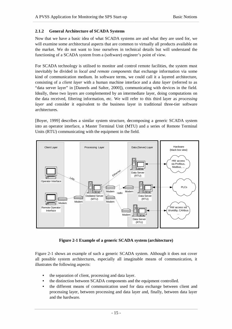
For SCADA technology is utilised to monitor and control remote facilities, the system mustinevitably be divided in local and remote components that exchange information via somekind of communication medium. In software terms, we could call it a layered architecture,consisting of a client layer with a human machine interface and a data layer (referred to as“data server layer” in [Daneels and Salter, 2000]), communicating with devices in the field.Ideally, these two layers are complemented by an intermediate layer, doing computations onthe data received, filtering information, etc. We will refer to this third layer as processinglayer and consider it equivalent to the business layer in traditional three-tier softwarearchitectures.
[Boyer, 1999] describes a similar system structure, decomposing a generic SCADA systeminto an operator interface, a Master Terminal Unit (MTU) and a series of Remote TerminalUnits (RTU) communicating with the equipment in the field.
Data (Server) LayerProcessing LayerClient Layer
Dediated Server(MTU)
Data Server(RTU)
HW accessvia Profibus,Modbus, ...
Operator Interface
Remote OperatorInterface
Data Server(RTU)
Data Server(RTU)
ModemModemradio
Modem
Modem
PLCs
HW access viaWorldfip, CANbus
...
Modem Modem
LANEthernet
Hardware(black box view)
Figure 2-1 Example of a generic SCADA system (architecture)
Figure 2-1 shows an example of such a generic SCADA system. Although it does not coverall possible system architectures, especially all imaginable means of communication, itillustrates the following aspects:
• the separation of client, processing and data layer.• the distinction between SCADA components and the equipment controlled.• the different means of communication used for data exchange between client and
processing layer, between processing and data layer and, finally, between data layerand the hardware.

A PVSS Application for Monitoring the SPS Start-up Basic Notions
- 16 -
After this overview of the physical distribution of the software components, we will elucidatethe tasks fulfilled by each of the layers.
2.1.2.1 Client Layer
In the centre of a SCADA system are its operators who are accessing the system by means ofa human machine interface (HMI), known in other parlance as an operator console or userinterface. This HMI consists of a video display unit (VDU) that displays real-time data aboutthe supervised process and of an input device for sending control instructions. What kinds ofVDU and input device are used depends largely on the complexity of the supervised system.In the case of very simple systems, a computer screen and some electrical switches wouldsuffice even though today’s PC-based SCADA systems almost exclusively use colour screensfor displaying data and often include audible signals to attract the operators’ attention in caseof emergency. Keyboard and mouse or touch screens are used for inputting the operators’commands or messages back to the process.
The following list gives an overview of functionality implemented in the client layer withoutclaiming to be complete.
• Combinations of synoptic diagrams, text and elements for navigation are displayedon multiple screens.
• Graphical objects and user interface elements can be linked to process variables inorder to display/reflect their value at run-time.
• Configuration panels and/or tools allow privileged users to modify the system’s set-up at run-time, to add/remove process variables and to customise the HMI.
• Trending charts visualise the evolution of certain process variables over time.Trending can be done with on-line data as well as with historical information storedin the system’s database.
• Alarm screens inform operators about pending alerts (e.g. if the value of a processvariable or expression leaves it pre-defined good-range)
To sum up, we can say that the client layer’s main task is to display/visualise information itreceives from the processing layer and to interact with the user.
2.1.2.2 Processing Layer
Having said the above, it is clear that the HMI directly interfaces with a master terminal unit(MTU). The advantages of having an MTU that acts as a system controller and hence as amediator between the operator interface and the RTUs can be summarised as follows:
• A series of tasks can be executed automatically and do not need any operatorinteraction. They can even be performed during the operator’s absence by means of abuilt-in scheduler that repeats pre-programmed actions at set intervals.
• A special alert behaviour can be triggered whenever a process variable passes a pre-defined threshold. The system can react by performing an emergency shut down,notifying the operators via an alert screen or other communication systems such asGSM phones or pagers.
• As all process variables are managed by the MTU that all clients connect to, allclients see the same values at the same time. If clients connected directly to the dataservers, synchronising the HMIs would be a much more difficult task.

A PVSS Application for Monitoring the SPS Start-up Basic Notions
- 17 -
• Complex computations, e. g. statistical functions, can be performed at the MTU-level. This avoids that all clients have to do the same computation, which would be awaste of computing power, especially if the clients are installed on averageworkstation machines.
The core feature of the MTU is certainly that it collects data from the data servers and thendistributes it to its clients, usually in an event-driven way. In this way, any piece ofinformation is transmitted from the remote location only once, which is crucial if remotefacilities are connected to the local components via a low-bandwidth communication medium.
2.1.2.3 Data (Server) Layer
The data server layer builds the final link to the hardware in a SCADA’s data acquisitionchain. It consists of one ore more data servers (called RTUs in Boyer’s terminology) that aredirectly connected to one or more MTUs via various communication media. As the dataservers are usually remote from the MTUs, long-distance communication media, such asradio, telephone lines, fibre optic cables etc., are used for this purpose. All the same, RTU andMTU can equally be connected via a LAN or, in exceptional cases, be installed on the samemachine, which will be the case at CERN.
The key task of a data server is data acquisition. The servers are connected to hardwareequipment, programmable logic controllers (PLCs) or, exceptionally, to other data acquisitionsystems via a variety of protocols. Usually, field buses (e.g. Profibus, Modbus, Bitbus,CANbus etc.) are used for communication.
In most cases, data is acquired from the hardware via a polling mechanism. In electroniccommunication, “polling” is the continuous interrogation of other programs or devices by oneprogram or device to see what state they are in, usually to see whether they are still connectedor want to communicate [WWW-WHATIS]. This implies that it is up to the data server todetect value changes and to forward these changes to the MTU as needed.
2.1.3 Features of SCADA Systems
At this stage, the reader is familiar with basic SCADA-related terms and knows how a typicalSCADA system is structured. The following section will draw attention to the features andfunctions that modern SCADA products should include.
[WWW-ITCO] and [NFESC, 1991] identify the following features:
• Data acquisition with a very high data throughput (up to several thousand values persecond)
• Ready-to-use drivers supporting standard communication protocols (e. g. field busprotocols, OPC etc.)
• Extensive processing power that is often distributed on several computers.• Extremely short response times.• Off-line processing.• Automatic control mechanisms that do not require the operators to be present all the
time (e. g. scheduled tasks, emergency actions etc.)• Alarm handling (i. e. reacting to values passing certain thresholds)• Data logging and archiving as well as the possibility to manipulate historical data.

A PVSS Application for Monitoring the SPS Start-up Basic Notions
- 18 -
• Access control mechanisms (e. g. an authorisation mechanism based on a user/groupconcept)
• User-friendly HMIs including many standard features (e.g. alarm display, trendingetc.) and often based on graphical operating systems
It goes without saying that this list is not complete. Even so, it gives a good overview and canserve as a starting point when evaluating and comparing different products available on themarket.
2.1.4 Benefits From the Use of SCADA
As it was mentioned before, the basic idea behind SCADA systems, as behind any remotecontrol mechanism, is to make it unnecessary for operators to be assigned to stay at orfrequently visit remote locations when those remote facilities are operating normally. From acontrol system’s perspective, the advantages of SCADA technology are obvious:
• Process data for monitoring is centralised.• Process equipment can be operated remotely.• The number of site visits required to remote stations is reduced (which leads to a
reduction of man-hours in operation).
All the same, we also want to draw attention to the benefits from the use of industrial SCADAsystems, which are usually commercial off-the-shelf (COTS) products, from an economicpoint of view:
• The effort invested in the development of an industrial SCADA system amounts to50/100 person years. Re-implementing all this functionality could be compared to re-inventing the wheel.
• The amount of specific development that needs to be performed by the end-user islimited.
• Technical support and maintenance are provided by the vendor.
In spite of these facts, SCADA technology is not applicable everywhere. The ensuing sectionwill therefore show the limitations of SCADA technology.
2.1.5 Limitations of SCADA Technology
Although there are hundreds of application areas for which SCADA technology is excellentlysuited, some process control and data acquisition functionality should not be handledremotely. [Boyer, 1999] cites two types of systems that should in no case depend on SCADA:(1) product measurement systems that are used for billing or paying taxes and are thusrequired to keep an audit trail and (2) safety-instrumented systems. In the first case, the reasonis very simple: systems used for the calculation of taxes are subject to government regulationsand require a paper trail allowing auditors to check whether proper accounting has been made.The case of safety-instrumented systems is more interesting. The failure of a safety-instrumented system may result in the injury or death of a person or cause damage toequipment or the environment. Consequently, safety-instrumented systems must meet certaindesign criteria that considerably increase the system’s complexity.

A PVSS Application for Monitoring the SPS Start-up Basic Notions
- 19 -
It is also worth pointing out that SCADA systems can only reduce the number of site visits aslong as the remote facilities are operating normally. If the remote system fails or does notrespond any more, the maintenance team still has to go on site.
2.1.6 Outlook to the Future
The current trend in SCADA industry is the migration to completely open systems, theambition to build “open architectures, allowing RTUs to be interchanged between systemsfrom different vendors” [NFESC, 1991]. It goes without saying that this goal is not new andnot at all limited to SCADA technology. The whole software industry is working on opensystem solutions (e.g. markets for interchangeable components supporting standardinterfaces) but, unfortunately, these noble intentions are often counteracted by economicconsiderations.
All the same, modern SCADA systems are usually designed to be extensible to a certaindegree. PVSS II, for example – the SCADA system we are going to take a closer look at inthe next chapter – permits the implementation of flexible control scripts and the developmentof additional modules using the same API the vendor used for implementing the system itself.
2.2 PVSS II – An Example of an Industry SCADA System
PVSS II, the abbreviation of “ProzeßVisualisierungs- und SteuerungsSystem”1, is anindustrial SCADA product developed by ETM, an Austrian company with its headquarters inEisenstadt, Burgenland. The main reasons why we will take a closer look at this product arethe following:
• After a three-year selection process, PVSS II has been selected as the CERNrecommended SCADA system for all LHC experiments.
• PVSS II is currently being evaluated as the standard SCADA system for the whole ofCERN.
• PVSS II forms the core of the SPS Restart Monitoring Application described in thiswork. Its concepts should thus be well known to the reader.
This chapter introduces PVSS. It is necessary to explain the architecture of a PVSS systemand the basic concepts used, in order to understand how the problem was solved.
2.2.1 Product Description
According to [ETM, 2000], PVSS II is an “object-oriented process visualisation and controlsystem [that] allows you to implement solutions tailored to specific customers”.
The vendor describes his product as follows:
“PVSS is an industry-neutral, universally implementable process-control system thatcan be used to help visualise, monitor and control technical sequences. It worksacross multiple computer platforms, is multilingual and has a modern, totally graphicUser Interface.” [ETM, 2000].
1 process visualisation and control system

A PVSS Application for Monitoring the SPS Start-up Basic Notions
- 20 -
The author’s experience with the product has shown that the citation above is correct – atleast as far as the qualities listed in the second sentence are concerned. This does not meanthat PVSS is perfect but it provides a range of features that make it superior to comparableproducts on the marked.
[WWW-ITCO] summarises the following strengths of PVSS that make it interesting in theHEP domain:
• It can run in a distributed manner with any of its processes running in a distributedmanner.
• It is possible to integrate distributed systems.• It has multi-platform support (Linux, Microsoft Windows NT 4.0 and Microsoft
Windows 2000)• It is device oriented with a flexible data point concept.• It has advanced scripting capabilities.• It has a flexible API allowing access to all features of PVSS from an external
application.
2.2.2 The Data Point Concept
PVSS II is based on various concepts. The central element that is found in all areas is itsflexible data point concept. External and internal variables, user authorisations, the activationof system images or alarms – all these things make use of so-called data points.
Before we go into details, we will define a couple of terms that will be helpful for theunderstanding of this thesis: A data point type (DPT) defines a named data structure andconsists of one or several typed data point elements (DPE). DPEs can themselves bestructures and thus have subordinated elements. The term data point (DP) designates a namedinstance of a DPT. Finally, so-called configs can be associated with DPEs and DPs. Configsare pre-defined sets of configuration information that are used for multiple purposes, e. g. forassociating DPEs with concrete process variables, for archiving, for the calculation ofstatistical values etc.
In many conventional SCADA systems, the organization of data is fixed and very inflexible.Each process variable (i. e. each value acquired from the hardware and each internal variable)is mapped to an individual data point, which means that complex systems are divided intohuge amounts of unstructured data points that are difficult to manage. ETM’s intention was tocreate a data point concept that is oriented at the real structure of the data being processed andthus “object-oriented”. Indeed, PVSS allows the definition of data point types (DPTs) thatconsist of several data point elements (DPEs) and are similar to structs in C or records inPASCAL. All the same, they have nothing to do with object-oriented classes in softwaretechnology, for they only define the structure of the data but do not include operations. If thevendor claims that the DP concept is object-oriented, this is only true if we reduce object-orientation to the possibility of creating structured data types that do not support inheritance,dynamic binding and polymorphism.
2.2.3 PVSS System Architecture – The Manager Concept
To get a better understanding of how PVSS works, the present section gives a brief overviewof the PVSS system architecture and introduces the reader to the PVSS II Manager concept.

A PVSS Application for Monitoring the SPS Start-up Basic Notions
- 21 -
In PVSS terminology, a manager is a process (known in other parlance as a task). Themanufacturer supplies several managers, each assuming a certain role in the system (e. g. dataacquisition, archiving, data processing, etc.). Additional managers can be developed by theuser – as a system extension – by means of the PVSS API.
Basically, PVSS II implements a client-server architecture with the event manager (EM)acting as a server for all other managers. The manufacturer presents his system as divided intofour layers that are depicted in Figure 2-2: (1) the user interface layer, (2) the processinglayer, (3) the communication and storage layer and (4) the driver layer. As we want to mapthis schema to the three-tier architecture described in 2.1.2, we will simply group (2) and (3)together.
PVSS system
EM
DrvOPC
DrvRK512
Drvuser
UIMoper
UIMoper
UIMdev
CM API
DM RM
Figure 2-2 General PVSS system architecture
We now take a look at the different standard managers and at the functionality they provide.
2.2.3.1 Event Manager (EM)
As it was mentioned above, the event manager is the central part of a PVSS system; receivingmessages, evaluating and distributing them to other managers. It acts as a kind of co-ordinatorthat all other managers connect to. Due to this, each PVSS system can only have one eventmanager, with the exception of a redundant system.
2.2.3.2 Database Manager (DM)
In collaboration with the event manager, the PVSS database manager is responsible for
(1) keeping a copy of the current process image (i. e. the current values of all data points)in memory and
(2) archiving value changes in a high-speed database.
As there can only be one copy of the current process image, there can only be one databasemanager per system, again, with the exception of a redundant PVSS system.
The archiving mechanism used by PVSS is very flexible. As all internal and external values(process variables, internal variables and configuration information) are stored in a database,all of them can be treated analogously. Individual value archives are used for different groups

A PVSS Application for Monitoring the SPS Start-up Basic Notions
- 22 -
of data points (e. g. for different parts of the monitored system) and it is up to the user todecide whether a value should be archived or not. All the value archives run as separateprocesses and their activity is co-ordinated by the Database Manager.
2.2.3.3 Control Manager (CM)
As mentioned in 2.1.6, PVSS was designed to be very open and extensible. A specialprogramming language called Control was integrated in the system to keep it “flexible anduniversal” [ETM, 2001]. Control is ANSI-C compatible and for that reason easy to learn forconfirmed programmers. It is utilised throughout all PVSS II modules for:
• linking user components to DPEs,• creating complex control functions,• testing and simulation tasks,• batch configuration of data points,• automatic execution of complex calculations,• etc.
One more argument for the use of Control is that it has already been used for the creation ofstandard components delivered with PVSS and is thus well tested by the vendor.
Control managers are used for loading custom or standard script libraries into memory andhence for making library functions accessible to other managers. Functions can be linked toDPEs via a special config or also to user interface components and are then executed in anevent-driven way. Control offers language constructs for multi-threading and so Controlmanagers can concurrently process several functional blocks.
2.2.3.4 Driver Managers (Drv).
Driver managers establish the communication link between PVSS and the hardware to besupervised/controlled. They are thus equivalent to the data servers in the generic SCADAarchitecture described in 2.1.2.
On the one hand, drivers for the most widely used protocols are delivered with the product(Muehbus, OPC, pager, Profibus, RK512, SSI and a simulator). On the other hand, the PVSSAPI also offers the possibility to implement further driver managers supporting proprietarycommunication protocols or recent developments. As the development of a PVSS driver is amajor concern of this work, we will come back to PVSS drivers later on.
2.2.3.5 User Interface Manager (UIM)
The User Interface Manager is the PVSS implementation of the generic client layer describedin 2.1.2.1. So-called PVSS panels are used for the visualisation of process status informationand for forwarding user input to the event manager. Such panels are created using a graphicaleditor and then saved as ASCII files, which makes them portable between UNIX andMicrosoft Windows platforms.
Panels can contain Control scripts for linking user interface components to DPE values. Thegraphical editor considerably facilitates the creation of such scripts and several wizardsgenerate scripts for implementing standard functionality (e. g. displaying the value of a DPEin a text field, changing the background colour of a UI element etc.).
A PVSS Application for Monitoring the SPS Start-up Basic Notions
- 23 -
2.2.3.6 Other Managers
The aforementioned managers can be found in virtually all PVSS systems. Some other, morespecialised managers are also supplied and used as needed, e. g. the redundancy manager, thedistribution manager or the ASCII manager. The ASCII Manager allows the export of PVSSconfiguration data (DPTs, DPEs configs etc.) from the internal high-speed database tospecially formatted ASCII files and also the import of configuration information from suchASCII files.
2.2.4 Scattered and Distributed PVSS Systems
These two terms are slightly confusing, as they have a similar meaning in English but areinterpreted differently in PVSS terminology. A scattered PVSS system is defined as onePVSS system with its managers distributed on several machines, whereas the term“distributed systems” designates an ensemble of independent PVSS systems that are linkedvia a network to mutually access their data points. This section provides explanations andexamples of use cases for both system types. Anticipating that both concepts will be used inthe course of the SPS Restart project, their understanding is essential.
2.2.4.1 Scattered Systems
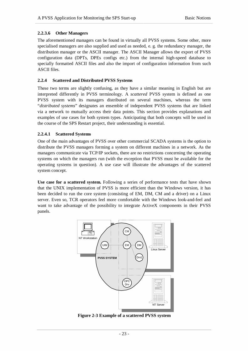
One of the main advantages of PVSS over other commercial SCADA systems is the option todistribute the PVSS managers forming a system on different machines in a network. As themanagers communicate via TCP/IP sockets, there are no restrictions concerning the operatingsystems on which the managers run (with the exception that PVSS must be available for theoperating systems in question). A use case will illustrate the advantages of the scatteredsystem concept.
Use case for a scattered system. Following a series of performance tests that have shownthat the UNIX implementation of PVSS is more efficient than the Windows version, it hasbeen decided to run the core system (consisting of EM, DM, CM and a driver) on a Linuxserver. Even so, TCR operators feel more comfortable with the Windows look-and-feel andwant to take advantage of the possibility to integrate ActiveX components in their PVSSpanels.
PVSS SYSTEM
EM DM
CM
UIM
NT Workstation
Linux Server
NT Server
OPCDrv
Drv1
Figure 2-3 Example of a scattered PVSS system

A PVSS Application for Monitoring the SPS Start-up Basic Notions
- 24 -
After the initial installation, new hardware, controlled by a driver using OLE for ProcessControl (OPC), is added to the system. As OPC is based on Microsoft’s OLE/COMtechnology, it is not available for Linux. The core system can still run on UNIX and only thedriver will be running on a Microsoft Windows NT 4.0 server. The structure of the resultingsystem is depicted in Figure 2-3.
2.2.4.2 Distributed Systems
As explained above, distributed systems allow different PVSS systems to communicate witheach other and to exchange data. This feature is very useful in large organizations, such asCERN, where several organizational units are responsible for data acquisition but also want toshare their data with others.
DELPHI:3CMS:2ATLAS:1
EM
DM
CM
DistM
Drv
EM
DM
CM
DistM
Drv
EM
DM
CM
DistM
Drv
Figure 2-4 Example of a distributed PVSS system
Distributed PVSS systems are linked via a separate distribution manager (DistM) that keepsthe linking of the systems as transparent to other PVSS managers as possible. A distributionmanager is able to maintain the logical connection to several distribution managers of otherPVSS systems over different networks. The drawback of the current PVSS distributionconcept is that all participating systems must know all other systems by their system id andtheir hostname (i.e. the host name of the machine running the event manager). Adding a newsystem therefore requires a lot of effort that could be saved if an intelligent naming servicewas used.
An (imaginary) example of a distributed PVSS system is illustrated in Figure 2-4. In this case,system LHC can access the data points of CMS and DELPHI (two LHC experiments). CMSand DELPHI, however, do not know each other and can only read data points provided byLHC.
2.2.5 The PVSS Redundancy Concept
If SCADA technology is used to supervise and control a large number of mission-criticalcomponents, it is vital to design the system for high dependability. One of the approaches toincrease the dependability of a system is the introduction of redundant components that backup primary resources in case of failure. The option of having a redundant system is an integralpart of PVSS II and is implemented as illustrated in Figure 2-5.
The same set of managers (EM, DM, CM, drivers etc.) is running on both systems, so thateach of them is able to operate independently of the other. Additionally, a special Redundancy

A PVSS Application for Monitoring the SPS Start-up Basic Notions
- 25 -
Manager (RM) is installed, with the task of co-ordinating the two systems, so that only one ofthem is active at a certain point in time. Ideally, the redundant systems should also dispose ofa redundant network connection, where one is used for the exchange of data (synchronisation)and the other one is used for the exchange of status information.
redu_host1 (active)
EM
redu_host2 (passive)
EM DM
DrvDrv
DM
1
CMCM
view_hostUIM
2RMRM
1
Figure 2-5 Architecture of a redundant PVSS system
A user of a redundant system (UIM) always connects to both redundant hosts and all requestsare forwarded to both event managers. All the same, the passive system (redu_host2 in Figure2-5) blocks the client calls. The active system processes the requests and then forwards theresults to the passive system. This mechanism that is equally used on the hardware side,avoids inconsistencies between the two systems.
2.3 The SL-Equip Package
SL-Equip represents a set of equipment access routines that “offer a flexible and genericinterface to heterogeneous equipment, such as 1553, GPIB, BITBUS, RS232, as well as tospecific user software, such as industrial PLCs or SPS data modules” ([Charrue, 1993]). Thispackage will be used for the implementation of a PVSS driver; we will therefore try tounderstand its underlying concepts.
The idea of the SL-Equip package – SL-Equip stands for SPS-LEP Equipment – is toexchange data with heterogeneous remote devices located all around the two accelerators.The client side, which we are mainly interested in, consists of a set of equipment accessroutines written in C.
2.3.1 System Architecture
Without going into details, this section gives a concise overview of how equipment access viaSL-Equip works and describes all the libraries and processes involved.
A PVSS Application for Monitoring the SPS Start-up Basic Notions
- 26 -
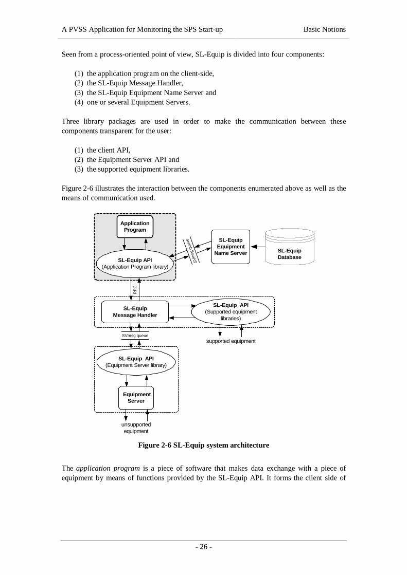
Seen from a process-oriented point of view, SL-Equip is divided into four components:
(1) the application program on the client-side,(2) the SL-Equip Message Handler,(3) the SL-Equip Equipment Name Server and(4) one or several Equipment Servers.
Three library packages are used in order to make the communication between thesecomponents transparent for the user:
(1) the client API,(2) the Equipment Server API and(3) the supported equipment libraries.
Figure 2-6 illustrates the interaction between the components enumerated above as well as themeans of communication used.
SVmsg queue
SL-Equip API(Application Program library)
ApplicationProgram
SL-EquipDatabase
SL-EquipEquipment
Name Server
SV
msg
que
ue
SL-EquipMessage Handler
SL-Equip API(Supported equipment
libraries)
supported equipment
RP
C
SL-Equip API(Equipment Server library)
EquipmentServer
unsupportedequipment
Figure 2-6 SL-Equip system architecture
The application program is a piece of software that makes data exchange with a piece ofequipment by means of functions provided by the SL-Equip API. It forms the client side of

A PVSS Application for Monitoring the SPS Start-up Basic Notions
- 27 -
SL-Equip and can be written in C/C++ or NODAL2. The PVSS driver to be developed in thecourse of this project will be such an application program.
The SL-Equip Name Server is a UNIX background process that handles the EquipmentDatabase containing all information that is needed by the client API in order to communicatewith the equipment.
The SL-Equip Message Handler, like the Name Server, is a UNIX background process thatreceives Equipment Messages sent from application programs and routes them according totheir types. It allows direct access to supported equipment as well as Equipment Serveraccess. It forwards the Equipment Message, waits for an answer and returns this answer to theapplication program.
When talking about equipment in the context of SL-Equip, we mean a piece of hardware thatis accessed by the application program. Several types of equipment are supported (1553,MPX, CAMC, GPIB and BITBUS) and can be directly accessed from the Message Handler.Other types of equipment must be accessed via special Equipment Servers.
An Equipment Server is a piece of software written by the user in order to directly controlequipment that is not supported or when there are complex actions to be performed on theequipment. Equipment Servers are written in C and process messages forwarded by the SL-Equip package.
2.3.2 Equipment Naming Conventions
Every piece of equipment that shall be accessed through the SL-EQUIP package is referencedby a logical name that can have one of two formats:
(a) it is made with two 6-byte strings called family and member or(b) it consist of a 64 bytes string.
We will always use form (a), as (b) is not supported by all equipment.
In addition to family and member, a so-called action designates a specific part of theequipment accessed. Like family and member, the action consists of a 6-byte string and is amandatory part of each SL-Equip client call. A user option allows some extra data to be sent,especially when the transaction is a read and the user needs to specify which data needs to beread from the equipment. Finally, a so-called mode specifies the type of data exchanged andits direction. The modes that are currently supported by the package are listed in Table 2-1.Modes starting with ‘R’ are used for read access, those starting with ‘W’ for write access andthose starting with ‘X’ for bi-directional access.
Mode ExplanationRBR, WBR, XBI Read/write 32-bit floating-point numbersRAR, WAR Read/write 32-bit floating-point numbers. The data will be converted to
an ASCII string before being transmitted.RS, WS Read/write ASCII strings (array of 8-bit characters)
2 NODAL is an interpreted language used by CERN and DESY, a high-energy physics centre inHamburg, Germany, to control their accelerator hardware. [WWW-HEUSE]
A PVSS Application for Monitoring the SPS Start-up Basic Notions
- 28 -
Mode ExplanationRBI, WBI Read/write short integers (16-bit)RAI, WAI Read/write short integers (16-bit). The data will be converted to an
ASCII string before being transmittedRB, WB, XB Read/write binary (8-bit) data
Table 2-1 Definition of SL-Equip modes
2.3.3 SL-Equip Client Calls
Having explained how SL-Equip components interact, we describe the three steps that need tobe performed by the application program to access equipment data:
(1) Resolve the equipment name.(2) Pack the data in a network format and call the equipment server concerned.(3) Receive the returned call, unpack the data and return a status to the calling program.
These three steps will be essential for developing the PVSS driver to SL-Equip.
2.4 The Super Proton Synchrotron
As the goal of this work is to develop an application for monitoring the start-up of the SuperProton Synchrotron (SPS), this section provides the reader with some backgroundinformation about CERN’s second largest accelerator.
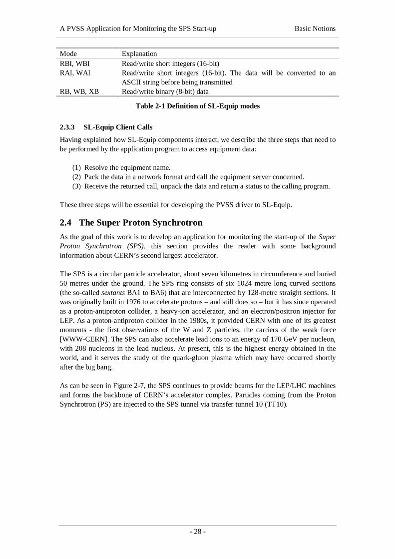
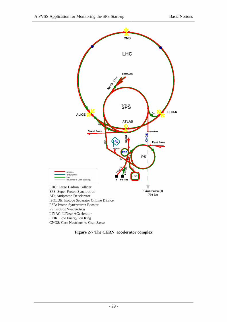
The SPS is a circular particle accelerator, about seven kilometres in circumference and buried50 metres under the ground. The SPS ring consists of six 1024 metre long curved sections(the so-called sextants BA1 to BA6) that are interconnected by 128-metre straight sections. Itwas originally built in 1976 to accelerate protons – and still does so – but it has since operatedas a proton-antiproton collider, a heavy-ion accelerator, and an electron/positron injector forLEP. As a proton-antiproton collider in the 1980s, it provided CERN with one of its greatestmoments - the first observations of the W and Z particles, the carriers of the weak force[WWW-CERN]. The SPS can also accelerate lead ions to an energy of 170 GeV per nucleon,with 208 nucleons in the lead nucleus. At present, this is the highest energy obtained in theworld, and it serves the study of the quark-gluon plasma which may have occurred shortlyafter the big bang.
As can be seen in Figure 2-7, the SPS continues to provide beams for the LEP/LHC machinesand forms the backbone of CERN’s accelerator complex. Particles coming from the ProtonSynchrotron (PS) are injected to the SPS tunnel via transfer tunnel 10 (TT10).
A PVSS Application for Monitoring the SPS Start-up Basic Notions
- 29 -
LHC: Large Hadron ColliderSPS: Super Proton SynchrotronAD: Antiproton DeceleratorISOLDE: Isotope Separator OnLine DEvicePSB: Proton Synchrotron BoosterPS: Protron SynchrotronLINAC: LINear ACceleratorLEIR: Low Energy Ion RingCNGS: Cern Neutrinos to Gran Sasso
protonsantiprotonsionsneutrinos to Gran Sasso (I)
Gran Sasso (I)730 km
East Area
West Area
Nor
th A
rea
LHC
SPS
PS
ALICELHC-b
CMS
ATLAS
COMPASS
TT10
TT10
Figure 2-7 The CERN accelerator complex

A PVSS Application for Monitoring the SPS Start-up Problem Description
- 30 -
3. PROBLEM DESCRIPTIONThis chapter presents an exhaustive description of the problem to be solved in the course ofthis thesis work. To start with, the general problem of an application monitoring the start-upof the SPS is presented and then, the overall task is broken down to subtasks to be solved bythe author himself. These subtasks are specified in detail.
3.1 Overview of the Problem
The project’s main objective is the development of a software application that facilitates themonitoring of all SPS subsystems involved in the accelerator’s restart after majorbreakdowns. In particular, the supervision of electrical installations, the vacuum system andthe raw and demineralised water circuits are concerned. The application based on a PVSSSCADA system shall provide an easy-to-use interface to monitor the subsystems of the SPSinvolved in the start-up procedure.
3.2 Parts of the Problem – Scope of the Project
This section focuses on the parts of the problem to be solved by the author that are presentedin this work. The task of developing a PVSS application for monitoring the SPS restart isbroken down to the following subtasks:
(1) the set-up and configuration of the PVSS system serving as a basis for theapplication,
(2) the development of a PVSS driver to acquire data from the SL-Equip middleware,(3) the implementation of a data loader for importing the static PVSS configuration
(DPTs, DPs, configs etc.) from an off-line database and(4) the design of some mimic diagrams for the application’s user interface.
3.2.1 Set-up and Configuration of the PVSS System
As PVSS will be used as the core of the SPS Restart Application, the set-up and configurationof the system in accordance with the functional requirements and constraints presented in thissection plays an essential role for the success of the project.
3.2.1.1 Design for High Dependability
Dependability is “that property of a computer system such that reliance can justifiably beplaced on the service it delivers” [Barbacci, 1995]. Software dependability includes a range ofcharacteristics, such as reliability, security and safety.
High dependability is required because the SPS Restart Application shall be used in two ofCERN’s main control rooms, available 24 hours a day, 365 days a year without interruption.The system design has to reflect this requirement.
3.2.1.2 Design for Data Exchange
As all data that is acquired from an equipment has to be transmitted via a dedicated controlnetwork, it would be a waste of bandwidth to acquire the same information twice for differentPVSS projects. As a consequence, a mechanism for sharing the data acquired with otherPVSS systems shall be provided.

A PVSS Application for Monitoring the SPS Start-up Problem Description
- 31 -
3.2.1.3 Implementation Constraints
Tests carried out at CERN in order to evaluate the performance of several SCADA productsunder consideration for the LHC experiments have shown that the Linux implementation ofPVSS II can handle twice as many value changes per second as its Windows (NT/2000)version (see [WWW-ITCO]). Seeing that the number of value changes per second is crucialfor the performance of a SCADA system, it was decided to install the core PVSS system forthe SPS Restart Application on a Linux platform. Like for all Linux Systems at CERN, aRedhat Linux 6.1 distribution adapted to CERN’s specific needs has to be used.
Nonetheless, as the Windows version of the PVSS user interface is more intuitive to use andalso allows the integration of ActiveX components, it was decided to run the PVSS front-end,i. e. the mimic diagrams for the SPS Restart Application, on Windows 2000 workstations. Formore details concerning the mimic diagrams, please refer to section 3.2.4.
3.2.2 Implementation of a PVSS Driver to SL-Equip
Since all electrical equipment involved in the start-up of the SPS is currently monitored andcontrolled by SL-Equip, a driver to this middleware has to be developed. Bi-directionalequipment access, i. e. reading out data provided by the equipment and sending commandinstructions to the hardware, shall be supported for integer, floating-point and string values.Furthermore, a mechanism to propagate SL-Equip error codes to the PVSS application shallbe provided.
As both, the PVSS API and the SL-Equip client-side library, are implemented in C/C++, thesame programming language shall be used for the implementation of the driver. Seeing thatthe core PVSS system shall run on Linux (see chapter 3.2.1.3) and the SL-Equip libraries arenot available for Windows, the driver will be developed for a Linux platform.
3.2.3 Implementation of a Data Loader for Automatic Data Point Generation
Apart from the basic set-up, specified in chapter 3.2.1, the data structures reflecting thestructure of the system to be monitored must be modelled and introduced into the SCADAsystem. For PVSS this is done by creating data point types (DPTs), data points (DPs) andconfigs that represent the supervised hardware. Subsequently, these data points have to beconnected to the hardware so that the available drivers can start acquiring data.
There is a general policy in the ST/MO group stipulating that configuration information forall control systems the group is responsible for must be stored in an external (off-line)database, the Technical Data Reference Database (TDRefDB). This is to avoid becomingdependent on a tool supplier and to facilitate the migration from one system to another. Forthis reason, all configuration information for the SPS Restart Application, i. e. DPTs, DPs,configs and comments, will first be modelled in the TDRefDB and subsequently be injectedinto the PVSS system by means of the PVSS ASCII Manager. A special data loader forextracting information from the TDRefDB and converting it into a format that is readable forthe ASCII Manager has to be developed. The author’s task with regard to the configurationdatabase can be broken down as follows:
(a) Define and implement a database structure in the TDRefDB that is suitable forstoring PVSS configuration information.
(b) Import existing configuration information from different sources into the newlycreated database structure.

A PVSS Application for Monitoring the SPS Start-up Problem Description
- 32 -
(c) Design and implement a data loading script that extracts PVSS configurationinformation from the TDRefDB and generates an ASCII Manager-compatibleconfiguration file.
3.2.4 Mimic Diagrams for the SPS Restart Application
Special attention has to be paid to the design and implementation of the user interface becausethis is the part of the system that operators will work with on a daily basis. For one thing, themimic diagrams have to be self-explaining and therefore resemble existing applications’ userinterfaces (especially regarding colour conventions, alarm signals etc.). Furthermore, it mustbe guaranteed that no damage is caused by accidental errors, such as the click on a wrongbutton.
The main screen of the SPS Restart Application, will depict a summary of the accelerator’sstate on a very high level (see section 2.4 for a description of the SPS). Each of the machine’ssextants and transfer tunnels will be represented by a box that is coloured in accordance withthe element’s current state (OK, Warning, Fault, No Data, etc.). The operator can click oneach of the boxes in order to descend in the hierarchy and get a more detailed view on thesextant in question. He will then see the states of the sextant’s subsystems (electricity,vacuum, demineralised water, etc.)
Although the mimic diagrams form an integral part of the SPS Restart Application, they willnot entirely be implemented by the author. The author will do one of the panels that can serveas an example for TCR operators who will implement the application’s user interface.

A PVSS Application for Monitoring the SPS Start-up System Design
- 33 -
4. SYSTEM DESIGNThis chapter presents the approach that was chosen to solve the problem described in theprevious chapter. From a software engineer’s point of view, we concentrate on the system’sdesign that specifies HOW the functional requirements settled down in chapter 3 are preparedfor the implementation. The objective of the design is to create a detailed specification oftasks and to create a basis for the implementation. The codification shall become a"mechanical" task. ([Mayr, 1998]).
Before we go into detail, a global view of the SPS Restart Application is given. Figure 4-1presents the project from three different perspectives.
TDSSL-Equip
File Server
PVSSWorkstation
Operator
CERN Intranet
Server 2Server 1
File Storage
1 2
4
(e) External Systems
(a) PVSS System
(c) External Storage
(b) Operator Interface
Data Acquisition(Driver)
(d) Configuration DB
TDRefDB
Data Loading
3
Use
r C
onne
ctio
n
12
D
B
C
A
Figure 4-1 Global view of the SPS Restart Application

A PVSS Application for Monitoring the SPS Start-up System Design
- 34 -
First of all, all computer systems and servers involved in the SPS Restart Application areidentified:
(a) PVSS servers. The servers on which the operational PVSS system will be set up.(b) Operators’ workstations. The workstations on which the application’s user interface
will be running. Although the diagram only contains one workstation, an arbitrarynumber of user interfaces can concurrently connect to the PVSS servers.
(c) Central file servers. The CERN central file servers where shared components,e. g. PVSS panel and script files for the application, will be stored.
(d) Database server. The Oracle 8i database server hosting the TDRefDB.(e) External systems. The systems that are used for communication with the SPS
hardware, i. e. TDS and SL-Equip.
Second, the main interactions between the systems listed above are pointed out:
(A) Data Acquisition. This arrow describes the bi-directional connection between thePVSS system and the external systems via the TDS and SL-Equip drivers. Data isacquired from the external systems and commands are sent to equipment in the field.
(B) Data Loading. This arrow describes the process of loading static configuration datafrom the TDRefDB into the PVSS system via the PVSS ASCII Manager.
(C) User Connection. This arrow describes the interaction between the PVSS UserInterface Manager running on the operator’s workstation and the core PVSS systemrunning on dedicated servers.
(D) Mimic Diagrams. This arrow describes the User Interface Manager’s access to ashared PVSS project directory that is located on a central file server. The shareddirectory can contain mimic diagrams, scripts and colour definitions that are used byseveral operators working on different machines.
Third, the parts of the project designed and implemented by the author are highlighted. Thenumbers (❶❷❸❹ ) reflect the order in which the subtasks are treated in this document:
1. Set-up of the PVSS system for the SPS Restart Application (section 4.1).2. Design and Implementation of a PVSS driver to SL-Equip (section 4.2).3. Development of a static PVSS configuration database (section 4.3).4. Design and implementation of the application’s user interface (section 4.4).
4.1 System Architecture
This section contains a specification of the PVSS system’s set-up, identifying the componentsrequired for the implementation of the SPS Restart Application and explaining theirdeployment in the operational environment. An overview of the proposed system’sarchitecture is depicted in Figure 4-2. The motivations and considerations that have lead tothis architecture are discussed in the following subsections.
4.1.1 Redundant PVSS System
In order to increase the dependability of the SCADA system, as required in 3.2.1.1, the PVSSsystem shall be set up in a redundant way. Since redundancy forms an integral part ofPVSS II, this design decision does not require any additional development effort, apart fromthe installation of a Redundancy Manager and the modification of several configuration files.As mentioned in 2.2.5, a redundant PVSS system consists of two identical systems, running
❶
❷
❸
❹
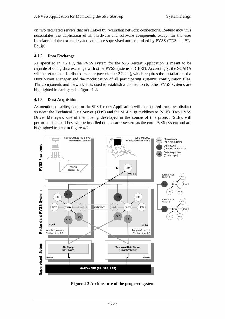
A PVSS Application for Monitoring the SPS Start-up System Design
- 35 -
on two dedicated servers that are linked by redundant network connections. Redundancy thusnecessitates the duplication of all hardware and software components except for the userinterface and the external systems that are supervised and controlled by PVSS (TDS and SL-Equip).
4.1.2 Data Exchange
As specified in 3.2.1.2, the PVSS system for the SPS Restart Application is meant to becapable of doing data exchange with other PVSS systems at CERN. Accordingly, the SCADAwill be set up in a distributed manner (see chapter 2.2.4.2), which requires the installation of aDistribution Manager and the modification of all participating systems’ configuration files.The components and network lines used to establish a connection to other PVSS systems arehighlighted in dark grey in Figure 4-2.
4.1.3 Data Acquisition
As mentioned earlier, data for the SPS Restart Application will be acquired from two distinctsources: the Technical Data Server (TDS) and the SL-Equip middleware (SLE). Two PVSSDriver Managers, one of them being developed in the course of this project (SLE), willperform this task. They will be installed on the same servers as the core PVSS system and arehighlighted in grey in Figure 4-2.
HP-UX
SL-Equip(RPC based)
HP-UX
Technical Data Server(SmartSockets®)
lnxoptim2.cern.chRedhat Linux 6.1
st_tsi
lnxoptim1.cern.chRedhat Linux 6.1
st_tsi
SLE
DrvData Acquisition(Driver Layer)
DistDistribution(Inter-PVSS System)
ReduRedundancy(Mutual Updates)
HARDWARE (PS, SPS, LEP)
Dist
Data Event
Ctrl
TDS
Event Data
Ctrl
TDSSLE
Dist
Red
un
dan
t P
VS
S S
yste
mS
up
ervi
sed
Syt
em
Windows 2000Workstation with PVSS
TSI_UI
CERN Central File Servercernhome07.cern.ch
UIMpanels,scripts, libsP
VS
S F
ron
t-en
d
Redu Reduredundant
Event Data
Ctrl
Drv2Drv1
Dist
External PVSSSystem 1
Event Data
Ctrl
Drv2Drv1
Dist
External PVSSSystem 2
Figure 4-2 Architecture of the proposed system
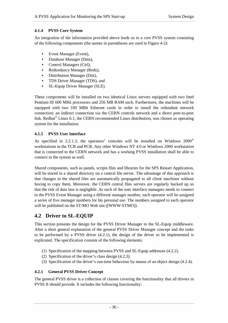
A PVSS Application for Monitoring the SPS Start-up System Design
- 36 -
4.1.4 PVSS Core System
An integration of the information provided above leads us to a core PVSS system consistingof the following components (the names in parentheses are used in Figure 4-2):
• Event Manager (Event),• Database Manager (Data),• Control Managers (Ctrl),• Redundancy Manager (Redu),• Distribution Manager (Dist),• TDS Driver Manager (TDS), and• SL-Equip Driver Manager (SLE).
These components will be installed on two identical Linux servers equipped with two IntelPentium III 600 MHz processors and 256 MB RAM each. Furthermore, the machines will beequipped with two 100 MBit Ethernet cards in order to install the redundant networkconnection: an indirect connection via the CERN controls network and a direct peer-to-peerlink. Redhat® Linux 6.1, the CERN recommended Linux distribution, was chosen as operatingsystem for the installation.
4.1.5 PVSS User Interface
As specified in 3.2.1.3, the operators’ consoles will be installed on Windows 2000®
workstations in the TCR and PCR. Any other Windows NT 4.0 or Windows 2000 workstationthat is connected to the CERN network and has a working PVSS installation shall be able toconnect to the system as well.
Shared components, such as panels, scripts files and libraries for the SPS Restart Application,will be stored in a shared directory on a central file server. The advantage of this approach isthat changes in the shared files are automatically propagated to all client machines withouthaving to copy them. Moreover, the CERN central files servers are regularly backed up sothat the risk of data loss is negligible. As each of the user interface managers needs to connectto the PVSS Event Manager using a different manager number, each operator will be assigneda series of five manager numbers for his personal use. The numbers assigned to each operatorwill be published on the ST/MO Web site ([WWW-STMO]).
4.2 Driver to SL-EQUIP
This section presents the design for the PVSS Driver Manager to the SL-Equip middleware.After a short general explanation of the general PVSS Driver Manager concept and the tasksto be performed by a PVSS driver (4.2.1), the design of the driver to be implemented isexplicated. The specification consists of the following elements:
(1) Specification of the mapping between PVSS and SL-Equip addresses (4.2.2).(2) Specification of the driver’s class design (4.2.3).(3) Specification of the driver’s run-time behaviour by means of an object design (4.2.4).
4.2.1 General PVSS Driver Concept
The general PVSS driver is a collection of classes covering the functionality that all drivers inPVSS II should provide. It includes the following functionality:
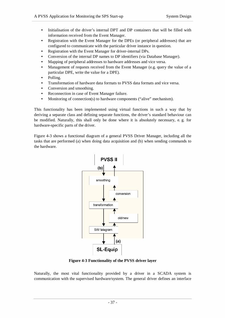
A PVSS Application for Monitoring the SPS Start-up System Design
- 37 -
• Initialisation of the driver’s internal DPT and DP containers that will be filled withinformation received from the Event Manager.
• Registration with the Event Manager for the DPEs (or peripheral addresses) that areconfigured to communicate with the particular driver instance in question.
• Registration with the Event Manager for driver-internal DPs.• Conversion of the internal DP names to DP identifiers (via Database Manager).• Mapping of peripheral addresses to hardware addresses and vice versa.• Management of requests received from the Event Manager (e.g. query the value of a
particular DPE, write the value for a DPE).• Polling.• Transformation of hardware data formats to PVSS data formats and vice versa.• Conversion and smoothing.• Reconnection in case of Event Manager failure.• Monitoring of connection(s) to hardware components (“alive” mechanism).
This functionality has been implemented using virtual functions in such a way that byderiving a separate class and defining separate functions, the driver’s standard behaviour canbe modified. Naturally, this shall only be done where it is absolutely necessary, e. g. forhardware-specific parts of the driver.
Figure 4-3 shows a functional diagram of a general PVSS Driver Manager, including all thetasks that are performed (a) when doing data acquisition and (b) when sending commands tothe hardware.
Figure 4-3 Functionality of the PVSS driver layer
Naturally, the most vital functionality provided by a driver in a SCADA system iscommunication with the supervised hardware/system. The general driver defines an interface
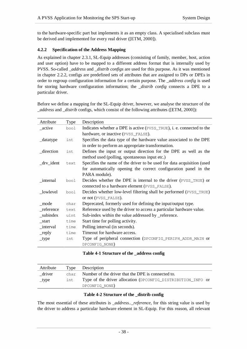
A PVSS Application for Monitoring the SPS Start-up System Design
- 38 -
to the hardware-specific part but implements it as an empty class. A specialised subclass mustbe derived and implemented for every real driver ([ETM, 2000]).
4.2.2 Specification of the Address Mapping
As explained in chapter 2.3.1, SL-Equip addresses (consisting of family, member, host, actionand user option) have to be mapped to a different address format that is internally used byPVSS. So-called _address and _distrib configs are used for this purpose. As it was mentionedin chapter 2.2.2, configs are predefined sets of attributes that are assigned to DPs or DPEs inorder to regroup configuration information for a certain purpose. The _address config is usedfor storing hardware configuration information; the _distrib config connects a DPE to aparticular driver.
Before we define a mapping for the SL-Equip driver, however, we analyse the structure of the_address and _distrib configs, which consist of the following attributes ([ETM, 2000]):
Attribute Type Description_active bool Indicates whether a DPE is active (PVSS_TRUE), i. e. connected to the
hardware, or inactive (PVSS_FALSE)._datatype int Specifies the data type of the hardware value associated to the DPE
in order to perform an appropriate transformation._direction int Defines the input or output direction for the DPE as well as the
method used (polling, spontaneous input etc.)_drv_ident text Specifies the name of the driver to be used for data acquisition (used
for automatically opening the correct configuration panel in thePARA module).
_internal bool Decides whether the DPE is internal to the driver (PVSS_TRUE) orconnected to a hardware element (PVSS_FALSE).
_lowlevel bool Decides whether low-level filtering shall be performed (PVSS_TRUE)or not (PVSS_FALSE).
_mode char Deprecated, formerly used for defining the input/output type._reference text Reference used by the driver to access a particular hardware value._subindex uint Sub-index within the value addressed by _reference._start time Start time for polling activity._interval time Polling interval (in seconds)._reply time Timeout for hardware access._type int Type of peripheral connection (DPCONFIG_PERIPH_ADDR_MAIN or
DPCONFIG_NONE)
Table 4-1 Structure of the _address config
Attribute Type Description_driver char Number of the driver that the DPE is connected to._type int Type of the driver allocation (DPCONFIG_DISTRIBUTION_INFO or
DPCONFIG_NONE)
Table 4-2 Structure of the _distrib config
The most essential of these attributes is _address.._reference, for this string value is used bythe driver to address a particular hardware element in SL-Equip. For this reason, all relevant

A PVSS Application for Monitoring the SPS Start-up System Design
- 39 -
SL-Equip address information (family, member, host, action, mode and user option) needs tobe coded into the _reference string. The following format was chosen for this effect:
family ”_” member [“#” host] “_” action “_” mode [“;” useroption].
The _reference string is encoded when the user adds or modifies the _address config for aparticular DPE. It is then transmitted to the driver concerned and, finally, decoded by thedriver. The information contained is packed into a suitable SL-Equip data structure and usedas a parameter in all SL-Equip library function calls.
The _subindex attribute will be zero by default and ignored by the driver, for it is only usefulif a part of a composite value acquired from the hardware is returned to PVSS (e. g. a singlebit out of a byte value). Our driver will not support this feature.
The _active attribute will be set PVSS_TRUE by default, meaning that the hardwareconnection is active. It can explicitly be set PVSS_FALSE by the user if data acquisition for acertain DPE shall temporarily be suspended.
The _direction attribute is very important, as it determines whether a value shall be read fromthe hardware or if a command shall be sent to SL-Equip. In the first case, the attribute’s valueis DPATTR_ADDR_MODE_INPUT_POLL (4), indicating that data shall be acquired via a pollingmechanism and that the parameters _start and _interval shall be taken into account fordetermining the polling rate. In the case of sending commands to SL-Equip, the valueDPATTR_ADDR_MODE_OUTPUT_SINGLE (5) is used.
Low-level comparison will be disabled by default. The _lowlevel flag will thus bePVSS_FALSE.
The SL-Equip driver will not require any internal DPs. The _internal attribute will thereforebe PVSS_FALSE by default.
The _mode attribute, which has been used to specify the input/output mode in earlier PVSSversions, has been deprecated in PVSS version 2.11.1. It has been replaced by a combinationof the _active, _direction, _lowlevel and _internal attributes. For reasons of backwardcompatibility, _mode will always contain the same value as _direction.
The attributes _start and _interval are used to set the polling rate inside the driver. Basically,the polling interval is specified in seconds. Additionally, a start time can be specified in orderto allow more complex time expressions, such as “daily at midnight”, “every Monday at1:00 PM”, etc. Although this feature will be implemented in order to increase the re-usabilityof the SL-Equip driver, it is not discussed in detail, for it is not relevant to the SPS RestartApplication project.
The _datatype attribute will not be specified by the user but directly derived from the PVSSdata type of the DPE concerned. The SL-Equip driver will support the PVSS data types listedin Table 4-3.

A PVSS Application for Monitoring the SPS Start-up System Design
- 40 -
PVSS Data Type Description Value of the _datatype AttributeDPEL_FLOAT 32-bit real number DPATTR_TRANS_FLOAT_TYPE
DPEL_DYN_FLOAT dynamic array of 32-bit realnumbers
DPATT_TRANS_FLOAT_TYPE
DPEL_INT 16-bit integer number DPATTR_TRANS_INT16_TYPE
DPEL_DYN_INT dynamic array of 16-bitinteger numbers
DPATTR_INT16_TYPE
DPEL_STRING max. 1024-byte string DPATT_TRANS_VISIBLE_TYPE
Table 4-3 Mapping of PVSS data types
As can be seen from Table 4-3, the driver will make no distinction between single values of acertain type and dynamic arrays of the same type. The difference will be handled internally bythe PVSS Driver API.
According to [ETM, 2000], the _address.._type attribute can assume the valuesDPCONFIG_NONE and DPCONFIG_PERIPH_ADDR_MAIN. As all DPEs managed by the SL-Equip driver will have an associated peripheral address, they will be assignedDPCONFIG_PERIPH_ADDR_MAIN by default. The same goes for the _distrib.._type attribute,which will always be DPCONFIG_DISTRIBUTION_INFO.
The _address.._drv_ident attribute will be “SL-EQUIP”. This value is used by the PVSSparameterisation module in order to determine the file name of the configuration panel to loadwhen a user wants to view the address configuration of a DPE.
The _distrib.._driver attribute associates a DPE with a concrete instance of a PVSS DriverManager. As the SL-Equip driver will connect to the Event Manager using the driver number2, this attribute will equally be 2 for all DPEs connected to SL-Equip.
Address information for DPEs connected to the SL-Equip driver will be entered/modified bythe user by means of a special PVSS panel that will be created in the course of this projectand integrated into the PVSS parameterisation (PARA) module.
The address mapping defined above will be relevant to the implementation of:
• the PVSS Driver Manager described in this section,• the off-line configuration database specified in 4.3 and• the configuration panel for adding/modifying/removing the _address config for a
DPE connected to the SL-Equip driver.
The next step in the driver design is the drawing up of an appropriate class design.
4.2.3 Class Design
As mentioned earlier, the implementation of the SL-Equip Driver Manager specified in 3.2.2will be based on the PVSS Application Programming Interface (API). This set of classes, datastructures and data types included in the PVSS distribution provides a standard mechanismfor extending PVSS functionality. The API is implemented in C++ and available forMicrosoft Windows NT 4.0 as well as Linux.

A PVSS Application for Monitoring the SPS Start-up System Design
- 41 -
The part of the API that is meant for the development of PVSS drivers, the so-called PVSSDriver Manager API, is designed as an object-oriented framework, i. e. a set of classes thatembodies an abstract design for solutions to a family of related problems, and supports reusesat a larger granularity than classes ([Johnson and Foote, 1998]). The advantage of having aframework rather than a traditional class library is that only a few classes need to be derivedand some methods must be overwritten in order to obtain a fully functional driver.Functionality that is common to all PVSS drivers, e. g. communication with the EventManager, adding/removing data points to/from the driver’s internal polling list, periodicprocessing of the polling list etc., is incorporated in the framework; the driver developer neednot re-implement it.
The most delicate task during the class design was to find out which classes of the frameworkneed to be derived and which methods have to be overwritten. As the documentation deliveredwith the PVSS API is rather incomplete as far as driver programming is concerned, athorough analysis of the framework had to be carried out before a class design could beestablished. The results of this analysis are presented in this section. Functionality that isimplemented in the framework is only covered as far as it is relevant to the implementation ofthe SL-Equip driver.
4.2.3.1 Core Classes
From a user’s point of view, three classes are considered as the SL-Equip driver’s core:
• The SL-Equip driver’s Manager class (SleDriver) is derived from the framework’sDrvManager class and responsible for co-ordinating communication with PVSS andSL-Equip respectively. Furthermore, it contains the main loop of the SL-Equipdriver, which manages its control flow (from initialisation to correct termination).
• The Hardware Service Handler class (SleSrvHdl) is derived from the framework’sHWService class and responsible for doing data exchange with SL-Equip (initialisingcommunication, reading the current value of a particular DPE and writing thechanged value of a DPE to the hardware).
• The Hardware Mapper class (SleMapper) is derived from the framework’sHWMapper class and performs the mapping between DP identifiers, theircorresponding peripheral addresses (encapsulated in PeriphAddr objects) and theircorresponding SL-Equip addresses (encapsulated in SleMapObj objects). Hence, itimplements part of the address mapping specified in section 4.2.2.
The relationships between these three classes are depicted in Figure 4-4, together with theirinheritance hierarchies. The base classes in the upper part of the drawing belong to theframework. Their methods are only listed as far as they are relevant to the implementation ofthe SL-Equip driver. The classes in the lower part of the figure (shaded in grey) have to beimplemented as a part of this work. Classes with a dotted border are treated in more detaillater in this chapter (see Figure 4-5 or Figure 4-6).

A PVSS Application for Monitoring the SPS Start-up System Design
- 42 -
SleDriver
+getHWObject() : HWObject*+install_HWMapper() : void+install_HWService() : void+signalHandler() : void
DrvManager
+getHWObject() : HWObject*+init() : PVSSboolean+install_HWMapper() : void+install_HWService() : void+mainLoop() : void+mainProcedure() : int+signalHandler() : void+toDp() : PVSSboolean+toHW() : PVSSboolean+getHWServicePtr() : HWService*+getHWMapperPtr() : HWMapper*+getSelfPtr() : DrvManager*
Manager
SleSrvHdl
+SleSrvHdl()+~SleSrvHdl()+initialize() : PVSSboolean+start() : PVSSboolean+stop() : void+generalQuery() : void+workProc() : void+singleQuery() : void+writeData() : PVSSboolean+hotLink2Internal() : void
HWService
+SleSrvHdl()+~SleSrvHdl()+initialize() : PVSSboolean+start() : PVSSboolean+stop() : void+generalQuery() : void+workProc() : void+singleQuery() : void+writeData() : PVSSboolean+hotLink2Internal() : void
1
1
installs 1
1
installs
1
1
SleMapper
+SleMapper()+~SleMapper()+actualize() : PVSSboolean+addDpPa() : PVSSboolean+addHWObject() : PVSSboolean+clrDpPa() : PVSSboolean#compare_HWcomponent() : int#compare_HWHW() : int
HWMapper
+SleMapper()+~SleMapper()+actualize() : PVSSboolean+addDpPa() : PVSSboolean+addHWObject() : PVSSboolean+clrDpPa() : PVSSboolean+compare_HWHW() : int+compare_HWcomponent() : int
1
1
SleMapObj
1
PV
SS
AP
I (co
mm
on to
all
driv
ers)
SL-
Equ
ip D
river
(sp
ecifi
c)
uses for hardwarecommunication
uses for hardwareaddress mapping
instantiates
Figure 4-4 Class diagram of the SL-Equip driver’s core classes
We now take a closer look at the classes mentioned above and define the functionality of theirmost important methods.
4.2.3.1.1 SL-Equip Driver Manager
SleDriver is the SL-Equip driver’s central class. It will be derived from the framework’sDrvManager class, which provides common functionality required by all PVSS DriverManagers. For one thing, it handles the connection to the Event and Database managers andthen, it co-ordinates communication with the hardware. In other words, it encapsulates theentire control flow within a generic PVSS Driver Manager.
Four virtual methods have to be overwritten in order to replace the generic functionality byfunctionality that is specific to the SL-Equip Driver Manager:
• install_HWService() instantiates and installs the SL-Equip driver’s HardwareService Handler (SleSrvHdl), which is then used by the framework to co-ordinatecommunication with the hardware.
• install_HWMapper()instantiates and installs the SL-Equip driver’s HardwareMapper (SleMapper) that is used by framework methods to perform the mapping ofPVSS to SL-Equip addresses and vice versa.

A PVSS Application for Monitoring the SPS Start-up System Design
- 43 -
• getHWObject() creates new SleMapObj objects and returns pointers to them,following the Factory Method design pattern described in [Gamma et al., 1994].
• signalHandler()handles UNIX signals received by the driver.
The install_HWService() and install_HWMapper() methods are called during thedriver’s initialisation. They instantiate objects of derived classes and assign them to staticpointers declared in the super class. This standard technique in object-oriented design allowsit to replace generic functionality foreseen in the framework by a more specificimplementation.
The getHWObject() method is called whenever the framework needs a new HWObject,e. g. when a new DPE is assigned to the driver.
The signalHandler() method is called whenever the driver receives a UNIX signal fromthe operating system (see [Toomey, 1995]). It handles SIGHUP and SIGTERM and calls amethod of its super class for all other signals.
4.2.3.1.2 The SL-Equip Hardware Service Handler
The SL-Equip Hardware Service Handler (SleSrvHdl) will be derived from the framework’sHWService class. It will implement the interface between the generic driver and the SL-Equip-specific part as far as communication with SL-Equip is concerned. As no initialisationis necessary for communicating with SL-Equip, only two virtual methods have to beoverwritten:
• singleQuery() polls a value from SL-Equip.• writeData() writes a value to SL-Equip.
Both methods receive a pointer to a HWObject containing the SL-Equip address of the valueto be read or written as an input parameter. In the case of writeData(), the HWObject alsocontains the value to be written.
4.2.3.1.3 The SL-Equip Hardware Mapper
As mentioned in section 4.2.3.1, the driver’s Hardware Mapper (SleMapper) is used formapping PVSS to SL-Equip addresses and vice versa. For one thing, it establishes aconnection between DP identifiers and peripheral addresses (i. e. the _reference stringscontained in the _address config). Secondly, it manages the connection between these_reference strings and their corresponding SL-Equip addresses.
The following methods have to be overwritten:
• addDpPa() is called to add a new peripheral address (PeriphAddr) received fromthe Event Manager to the driver’s internal list. Furthermore, it creates a newSleMapObj from the peripheral address and calls the addHWObject method.
• addHWObject() adds the HWObject it receives as an input parameter to the driver’sinternal list.
• clrDpPa() is called to remove a data point’s peripheral address and thecorresponding Hardware Object from the driver’s internal lists. This is the case whenthe user deletes a DPE assigned to the SL-Equip driver in the parameterisationmodule or when he removes/changes such a DPE’s _address config.
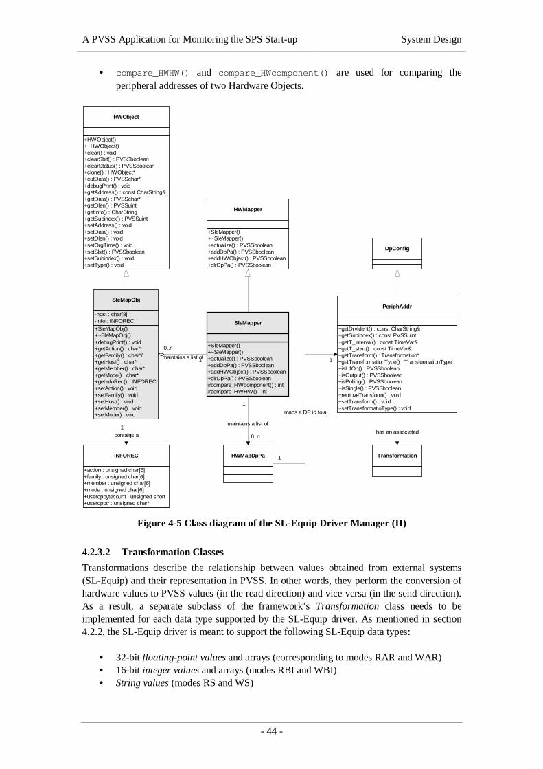
A PVSS Application for Monitoring the SPS Start-up System Design
- 44 -
• compare_HWHW() and compare_HWcomponent() are used for comparing theperipheral addresses of two Hardware Objects.
SleMapper
+SleMapper()+~SleMapper()+actualize() : PVSSboolean+addDpPa() : PVSSboolean+addHWObject() : PVSSboolean+clrDpPa() : PVSSboolean#compare_HWcomponent() : int#compare_HWHW() : int
HWMapper
+SleMapper()+~SleMapper()+actualize() : PVSSboolean+addDpPa() : PVSSboolean+addHWObject() : PVSSboolean+clrDpPa() : PVSSboolean
HWObject
+HWObject()+~HWObject()+clear() : void+clearSbit() : PVSSboolean+clearStatus() : PVSSboolean+clone() : HWObject*+cutData() : PVSSchar*+debugPrint() : void+getAddress() : const CharString&+getData() : PVSSchar*+getDlen() : PVSSuint+getInfo() : CharString+getSubindex() : PVSSuint+setAddress() : void+setData() : void+setDlen() : void+setOrgTime() : void+setSbit() : PVSSboolean+setSubindex() : void+setType() : void
SleMapObj
+SleMapObj()+~SleMapObj()+debugPrint() : void+getAction() : char*+getFamily() : char*/+getHost() : char*+getMember() : char*+getMode() : char*+getInfoRec() : INFOREC+setAction() : void+setFamily() : void+setHost() : void+setMember() : void+setMode() : void
-host : char[8]-info : INFOREC
INFOREC
+action : unsigned char[6]+family : unsigned char[6]+member : unsigned char[6]+mode : unsigned char[6]+useropbytecount : unsigned short+useropptr : unsigned char*
1
1contains a
1
0..n
maintains a list of
PeriphAddr
+getDrvIdent() : const CharString&+getSubindex() : const PVSSuint+getT_interval() : const TimeVar&+getT_start() : const TimeVar&+getTransform() : Transformation*+getTransformationType() : TransformationType+isLlfOn() : PVSSboolean+isOutput() : PVSSboolean+isPolling() : PVSSboolean+isSingle() : PVSSboolean+removeTransform() : void+setTransform() : void+setTransformatioType() : void
Transformation
has an associated
1
0..n
maintains a list of
DpConfig
HWMapDpPa 1
1
maps a DP id to a
Figure 4-5 Class diagram of the SL-Equip Driver Manager (II)
4.2.3.2 Transformation Classes
Transformations describe the relationship between values obtained from external systems(SL-Equip) and their representation in PVSS. In other words, they perform the conversion ofhardware values to PVSS values (in the read direction) and vice versa (in the send direction).As a result, a separate subclass of the framework’s Transformation class needs to beimplemented for each data type supported by the SL-Equip driver. As mentioned in section4.2.2, the SL-Equip driver is meant to support the following SL-Equip data types:
• 32-bit floating-point values and arrays (corresponding to modes RAR and WAR)• 16-bit integer values and arrays (modes RBI and WBI)• String values (modes RS and WS)
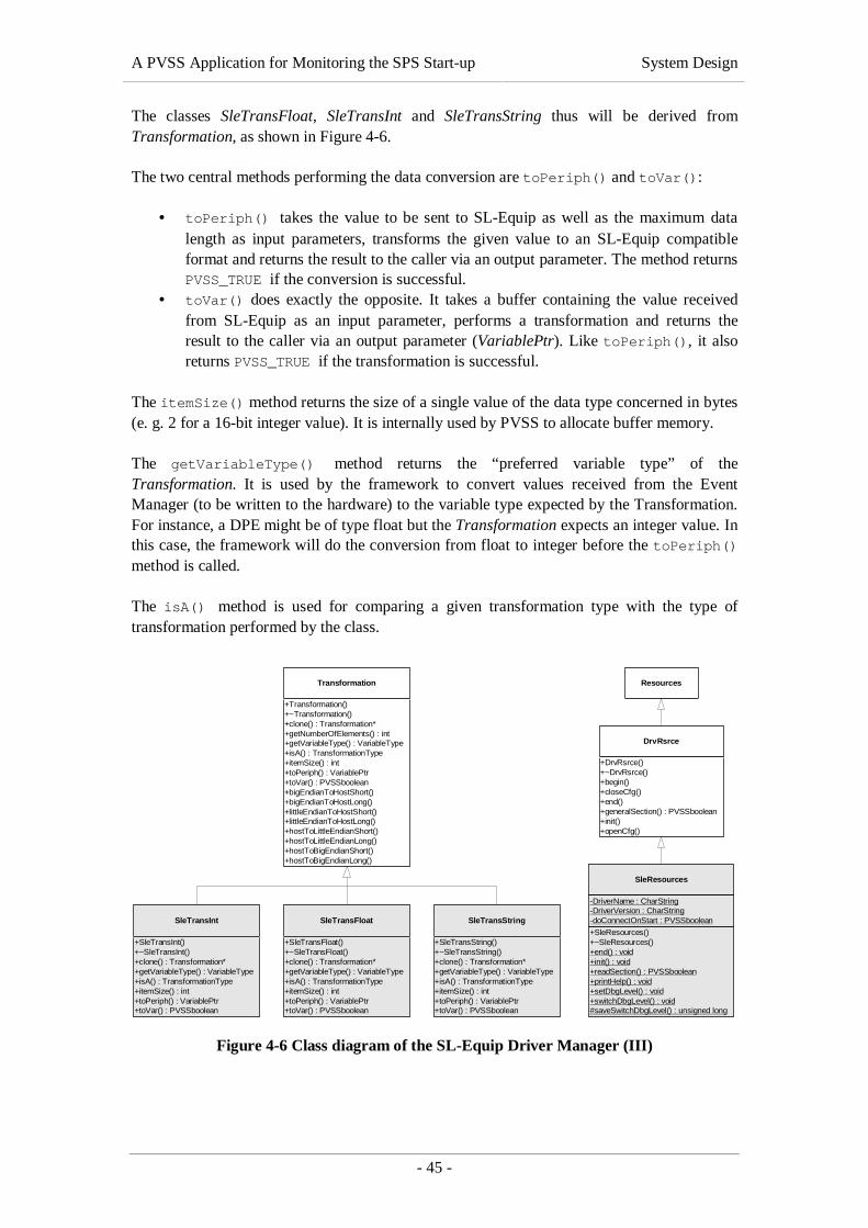
A PVSS Application for Monitoring the SPS Start-up System Design
- 45 -
The classes SleTransFloat, SleTransInt and SleTransString thus will be derived fromTransformation, as shown in Figure 4-6.
The two central methods performing the data conversion are toPeriph() and toVar():
• toPeriph() takes the value to be sent to SL-Equip as well as the maximum datalength as input parameters, transforms the given value to an SL-Equip compatibleformat and returns the result to the caller via an output parameter. The method returnsPVSS_TRUE if the conversion is successful.
• toVar() does exactly the opposite. It takes a buffer containing the value receivedfrom SL-Equip as an input parameter, performs a transformation and returns theresult to the caller via an output parameter (VariablePtr). Like toPeriph(), it alsoreturns PVSS_TRUE if the transformation is successful.
The itemSize() method returns the size of a single value of the data type concerned in bytes(e. g. 2 for a 16-bit integer value). It is internally used by PVSS to allocate buffer memory.
The getVariableType() method returns the “preferred variable type” of theTransformation. It is used by the framework to convert values received from the EventManager (to be written to the hardware) to the variable type expected by the Transformation.For instance, a DPE might be of type float but the Transformation expects an integer value. Inthis case, the framework will do the conversion from float to integer before the toPeriph()method is called.
The isA() method is used for comparing a given transformation type with the type oftransformation performed by the class.
SleTransInt
+SleTransInt()+~SleTransInt()+clone() : Transformation*+getVariableType() : VariableType+isA() : TransformationType+itemSize() : int+toPeriph() : VariablePtr+toVar() : PVSSboolean
SleTransFloat
+SleTransFloat()+~SleTransFloat()+clone() : Transformation*+getVariableType() : VariableType+isA() : TransformationType+itemSize() : int+toPeriph() : VariablePtr+toVar() : PVSSboolean
SleTransString
+SleTransString()+~SleTransString()+clone() : Transformation*+getVariableType() : VariableType+isA() : TransformationType+itemSize() : int+toPeriph() : VariablePtr+toVar() : PVSSboolean
Transformation
+Transformation()+~Transformation()+clone() : Transformation*+getNumberOfElements() : int+getVariableType() : VariableType+isA() : TransformationType+itemSize() : int+toPeriph() : VariablePtr+toVar() : PVSSboolean+bigEndianToHostShort()+bigEndianToHostLong()+littleEndianToHostShort()+littleEndianToHostLong()+hostToLittleEndianShort()+hostToLittleEndianLong()+hostToBigEndianShort()+hostToBigEndianLong()
Resources
SleResources
+SleResources()+~SleResources()+end() : void+init() : void+readSection() : PVSSboolean+printHelp() : void+setDbgLevel() : void+switchDbgLevel() : void#saveSwitchDbgLevel() : unsigned long
-DriverName : CharString-DriverVersion : CharString-doConnectOnStart : PVSSboolean
DrvRsrce
+DrvRsrce()+~DrvRsrce()+begin()+closeCfg()+end()+generalSection() : PVSSboolean+init()+openCfg()
Figure 4-6 Class diagram of the SL-Equip Driver Manager (III)

A PVSS Application for Monitoring the SPS Start-up System Design
- 46 -
4.2.3.3 Utility Classes
Two more classes have to be derived: the SL-Equip Hardware Object (SleMapObj) classmentioned before and the SL-Equip Driver Resources (SleResources) class that will read-outdriver-specific configuration information from the PVSS configuration file.
4.2.3.3.1 SL-Equip Hardware Objects
The SleMapObj class has already been mentioned when talking about the SleMapper class(section 4.2.3.1.3). As shown in Figure 4-5, it is derived from the framework’s HWObjectclass. Its main task is to encapsulate the address information for a single DPE. Furthermore, itcontains a pointer to a buffer in which the periphery data, i. e. the value that has been acquiredfrom SL-Equip and has to be sent to PVSS, is stored. An additional attribute contains the sizeof this buffer in bytes. Moreover, the class manages the DPE’s transformation type and somestatus information indicating whether the value received from the hardware is valid or not.
Most of these attributes are general and therefore managed by the super class. However, thehardware address, which is received from the Event Manager in the form of the _referencestring described in 4.2.2, has to be decoded and split into parts corresponding to an SL-Equipaddress (family, member, host, action, mode and user option). These parts will then be storedin an INFOREC structure defined by the SL-Equip API, which can directly be used in SL-Equip function calls.
Theoretically, the SleMapObj would not need any additional methods, as the INFORECstructure can be constructed from the PeriphAddr parameter passed to the classes’constructor. As the information might change later, however, getXXX() and setXXX()methods will be implemented for each part of the SL-Equip address.
4.2.3.3.2 SL-Equip Resources
The SleResources class is derived from the framework’s DrvRsrce class, as shown in Figure4-6. This class represents the driver’s interface to its resources (i. e. the PVSS configurationfile). As driver-specific functions primarily relate to driver-internal data points, which ourdriver will not have, the begin(), readSection() and end() methods will only containdummy functionality.
The setDbgLevel() and switchDbgLevel() methods will be used for debugging purposesand are described in the implementation chapter.
4.2.4 Object Design
The class design contained in the previous section describes the static structure of the SL-Equip Driver Manager. This section specifies its dynamic behaviour at run-time.
During its “lifetime” (= run-time) the driver has to pass the following three phases:
(1) Initialisation(2) Hardware activity(3) Termination
These phases are described in the ensuing sections.

A PVSS Application for Monitoring the SPS Start-up System Design
- 47 -
4.2.4.1 Initialisation
At its start-up, the driver instantiates its various “modules” (Resources, Driver Manager,Hardware Mapper, Hardware Service Mapper etc.) and initialises them. For the user of theframework, this is a fairly simple task:
(1) The static init() method of the SleResources class has to be called, which causesthe framework to read the driver-specific section of the PVSS configuration file andto store the values found in its static member variables.
(2) A signal handler for SIGHUP and SIGTERM must be installed.(3) An instance of the SleDriver class has to be created and its mainProcedure()
method must be invoked. From this time on, the framework takes over control.
However, we also want to understand what happens internally during this initialisation phase,at least as far as the classes that have to be implemented for the SL-Equip driver are involved.This simplified initialisation process is depicted in Figure 4-7. A more complete view of theinitialisation process is described below.
main()
(SleResources)
init()
config
initialize()
start()
install_HWService()
(SleSrvHdl)
install_HWMapper()
(SleMapper)
(SleDriver)
mainProcedure()
init
connectToData
connectToEvent
mainLoop
Figure 4-7 Object model of the SL-Equip driver during its initialisation

A PVSS Application for Monitoring the SPS Start-up System Design
- 48 -
First of all, the Driver Manager’s init() method is called, which initiates the creation ofseveral objects:
• a DP Container (framework’s DpContainer class)• a DP Config Manager (framework: DpConfigManager class)• an SL-Equip Hardware Mapper (our SleMapper class)• an SL-Equip Hardware Service Handler (our SleSrvHdl class)• a Polling List (framework’s PollList class).
After that, the SL-Equip driver will connect to the Database Manager (connectToData()).As a result, it will receive the _address and _distrib configs of all DPEs connected to it. Theseconfigs will be used to build up the driver’s internal lists by means of the Hardware Mapper’saddDpPa() method.
Subsequently, the communication with SL-Equip is initialised by a call to the HardwareService Handler’s initialize() method. As soon as a connection to the Event Managerhas been established (connectToEvent()), the hardware activity can be started invoking theHardware Service Handler’s start() method.
At this point in time, the driver has taken up its regular activity and enters in its main loop(DrvManager.mainLoop()).
4.2.4.2 Hardware Activity
Until it terminates, the driver remains in its main loop, in which it waits for messages fromthe Event Manager, checks whether DPs should be polled and cyclically calls theworkProc() method of the SL-Equip Hardware Service Handler. This method will be emptyin the SL-Equip driver’s implementation because all data is acquired via the pollingmechanism described below.
For handling the polling, the driver keeps an internal list in which the DPs to be polled arenoted with their next polling time. When such a time is reached, the Hardware ServiceHandler’s singleQuery() method is called with the Hardware Object concerned as an inputparameter. The singleQuery() method retrieves the requested value by means of an SL-Equip function call (EQUIP()) and then invokes the Driver Manager’s toDp() method inorder to communicate the new value to PVSS. The toDp() method accepts the new HardwareObject, performs a low-level old-new comparison as needed, converts it to a PVSS-internaldata format (using a suitable Transformation subclass, dependent on the data format),performs conversion and smoothing as necessary and sends the value to the Event Manager(if it was not smoothed away in the previous steps). After the return of the singleQuery()method, the new polling time for the DP is calculated and sorted into the polling list.
In the command direction, the toHW() method looks after the conversion of PVSS DPs tohardware objects, which are then sent to SL-Equip by the Hardware Service Handler’swriteData() method. This method calls an SL-Equip library function (EQUIP()) andreturns.
As mentioned above, this main loop is repeated until the driver is forced to exit.

A PVSS Application for Monitoring the SPS Start-up System Design
- 49 -
4.2.4.3 Termination
When the driver receives SIGKILL or SIGTERM from the operating system, it has toterminate. Before it exits, however, the connection to the peripheral devices (SL-Equip) mustbe closed down correctly. For this reason, the driver’s signal handler catches SIGTERM andsets a flag in the DrvManager class that causes the mainLoop() method to return. After that,the stop() method of the Hardware Service Handler (SleSrvHdl) is called by themainProcedure() before the program terminates.
4.3 Static Data Definition in an Off-line Database
This section proposes a solution to the problem described in chapter 3.2.3. First of all, arelational database structure suitable for storing PVSS configuration information has to bedesigned (4.3.1). After that, existing configuration information has to be analysed, validated,completed and inserted into the TDRefDB (4.3.2), and, finally, the information has to beextracted from the configuration database and imported in the SCADA system using thePVSS ASCII Manager (4.3.3).
4.3.1 Database Design
The table structure for the TDRefDB has been designed in co-operation with the ST/MOdatabase experts, R. Martini and S. Roy, who ensured that the ST/MO group’s databasedesign standards were complied with (see 4.3.1.1).
The final objective of the database design was to model all PVSS configuration information ina relational database structure, so that data point types (DPTs), data points (DPs) and configscan be defined in the database, extracted to ASCII files and, finally, injected to PVSS usingthe PVSS ASCII Manager. A definition of the PVSS data point concept (including DPTs,DPs, DPEs and configs) was presented in 2.2.2 and shall not be repeated here.
Before we devote ourselves fully to the database structure that was designed for the PVSSdata loader, we fix some general design rules that will lead us to a more homogenous databasedesign.
4.3.1.1 General Design Rules
According to ST/MO standards, applications must never access data directly via the tablescontaining the records but via so-called “user views” that present the data in an easy-to-useformat. Public synonyms for these views will be created in a separate database account. Thisapproach considerably facilitates unforeseen modifications in the database structure at a laterpoint in time. While underlying table structures may change, the user views on the data willalways remain the same and applications using the database need not be modified.Additionally, the risk of accidental loss of data is minimised as the user views are read-onlyand only very few authorised users have write access to the real data.
It was decided to design the table structure for referential integrity rather than usability orperformance. Usability will be implemented in the user views mentioned above. Since theTDRefDB is an off-line database and will only be used for periodic updates of the internalPVSS high-speed database, performance aspects are secondary. Referential integrity,however, must always be kept in mind. The user shall not be able to enter invalid values, forthis will inevitably lead to problems when the PVSS on-line database is loaded withTDRefDB data.

A PVSS Application for Monitoring the SPS Start-up System Design
- 50 -
To guarantee referential integrity without influencing the flexibility of the database design,surrogate keys must be used wherever possible. A surrogate key is a unique primary keygenerated by the DBMS (e. g. by a sequence) that is not derived from any data in the databaseand whose only significance is to act as the primary key. The use of surrogate keys increasesthe flexibility of the database design, for real data in the tables can be changed withoutaffecting dependent records.
Furthermore, some naming conventions have been established that will make the designeasier to understand and the database easier to use. The following naming conventions will beapplied:
• All table names shall start with the prefix “PVSS_”, in order to distinguish them fromother TDRefDB tables. Moreover, all view names will start with “VPVSS_” for thesame reason.
• All table and view names shall be descriptive and contain the singular name of theentity they represent. The name of the entity may be shortened only if theabbreviation is well known in the context of PVSS (e.g. DPT, DP, DPE etc.).
• Several parts of a name shall be separated by an underscore.• All fields of a table shall start with a prefix abbreviating the name of the table or view
concerned (e.g. “dpt_” for the PVSS_DPT table).• Fields that are directly related to a PVSS entity, e. g. the _type attribute of the
_address config, shall conserve this name in the database (e.g. addr_type).• Names of UNIQUE constraints shall start with the prefix “unique_” and contain the
names of the fields the constraint applies to.• Names of FOREIGN keys guaranteeing the referential integrity of the database shall
start with the prefix “fk_” and contain at least the name(s) of the referenced field(s).• Sequences shall be named like the fields they are used for (e.g. DPT_ID for the field
PVSS_DPT.DPT_ID).
Keeping these simple design and naming rules in mind, the database structure will be easy tounderstand and easy to use.
4.3.1.2 TDRefDB Table Structure
Based on the file format described in 4.3.3.1, the table structure depicted in Figure 4-8 wasdesigned. It will form the basis of our off-line PVSS configuration database and will bedescribed in this section.
Several groups of tables have been identified according to their purpose:
(1) PVSS Reference Tables. The tables PVSS_DISTRIB_TYPE, PVSS_DPE_TYPE,PVSS_ADDRESS_DATATYPE PVSS_ADDRESS_MODE and PVSS_ADDRESS_TYPE
contain simple (name, value) pairs that represent PVSS constant definitions. Theseconstants are used in PVSS to define the type of a DPE, the address mode of a driver,etc. The sole purpose of the reference tables is to guarantee the referential integrity ofthe database and to prevent the user from entering invalid constant values. The tableswill have to be filled with data manually before any other tables can be filled.
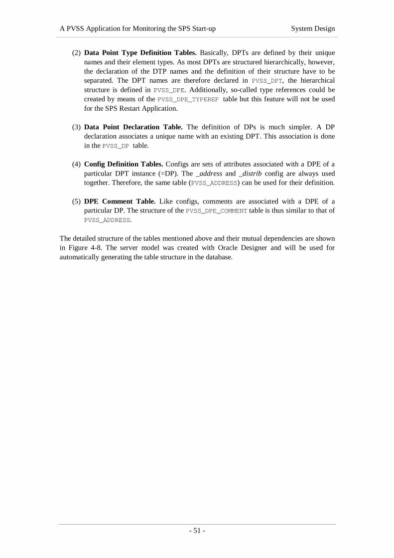
A PVSS Application for Monitoring the SPS Start-up System Design
- 51 -
(2) Data Point Type Definition Tables. Basically, DPTs are defined by their uniquenames and their element types. As most DPTs are structured hierarchically, however,the declaration of the DTP names and the definition of their structure have to beseparated. The DPT names are therefore declared in PVSS_DPT, the hierarchicalstructure is defined in PVSS_DPE. Additionally, so-called type references could becreated by means of the PVSS_DPE_TYPEREF table but this feature will not be usedfor the SPS Restart Application.
(3) Data Point Declaration Table. The definition of DPs is much simpler. A DPdeclaration associates a unique name with an existing DPT. This association is donein the PVSS_DP table.
(4) Config Definition Tables. Configs are sets of attributes associated with a DPE of aparticular DPT instance (=DP). The _address and _distrib config are always usedtogether. Therefore, the same table (PVSS_ADDRESS) can be used for their definition.
(5) DPE Comment Table. Like configs, comments are associated with a DPE of aparticular DP. The structure of the PVSS_DPE_COMMENT table is thus similar to that ofPVSS_ADDRESS.
The detailed structure of the tables mentioned above and their mutual dependencies are shownin Figure 4-8. The server model was created with Oracle Designer and will be used forautomatically generating the table structure in the database.

A PVSS Application for Monitoring the SPS Start-up System Design
- 52 -
Figure 4-8 Server model of the TDRefDB table structure for PVSS configuration data

A PVSS Application for Monitoring the SPS Start-up System Design
- 53 -
4.3.1.2.1 Reference Tables
The structure of the reference tables PVSS_DISTRIB_TYPE, PVSS_DPE_TYPE,PVSS_ADDRESS_DATATYPE, PVSS_ADDRESS_MODE and PVSS_ADDRESS_TYPE is identical:
(1) The numeric xxx_id column corresponds to the value of the PVSS constantrepresented by a record and forms the table’s primary key. The primary key will laterbe referenced by other tables, notably by PVSS_ADDRESS, PVSS_DPT and PVSS_DPE.
(2) The xxx_name column corresponds to a PVSS constant’s name, which must equallybe unique. The column is therefore protected by a UNIQUE constraint.
(3) The xxx_comment column is optional and can contain a free textual description ofthe constant’s purpose.
4.3.1.2.2 Data Point Type Definitions
As mentioned above, DPT definitions will require entries in two tables: PVSS_DPT andPVSS_DPE.
PVSS_DPT will contain a list of all DPT names and their associated element type from thePVSS_DPE_TYPE table:
(1) The numeric dpt_id column is the table’s primary key. It does not correspond toanything in PVSS (surrogate key) and is created by the DPT_ID sequence.
(2) The dpt_name column will contain the name of the DPT. As this name has to beunique in PVSS, the dpt_name column is protected by a UNIQUE constraint.
(3) The dpt_type column defines the element type of the DPT. In most of the cases,the element type will be DPEL_STRUCT (1) from the PVSS_DPE_TYPE table andthe subordinated elements will be defined in PVSS_DPE.
(4) The dpt_comment column can contain an optional comment describing the DPT inplain text.
PVSS_DPE describes the structure of the DPTs. Each PVSS_DPE record consists of thefollowing elements:
(1) dpe_id: a unique numeric identifier for the element that will be generated by theDPE_ID sequence and is the table’s primary key (surrogate key).
(2) dpe_dp_id: the identifier of the DPT from PVSS_DPT the element belongs to. Thiscolumn must reference an existing DPT identifier, which is enforced by a foreign keyrelationship.
(3) dpe_name: that name of the DPE that has to be unique within each DPT definition.Unicity is enforced by a UNIQUE constraint on the dpe_dp_name and dpe_dp_dptcolumns.
(4) dpe_type: the element’s data type from PVSS_DPE_TYPE.type_id. Thisrelationship is also enforced by a foreign key.
(5) dpe_parent: this column will be used to build hierarchical DPTs. By default, itsvalue will be NULL. If the DPE has a different parent than the DPT itself, however,it will contain the identifier of the parent DPE. The column is protected by a foreignkey to PVSS_DPE.dpe_id.
(6) dpe_full_name: the full name of a DPE can differ from its name if the dpe_parentcolumn is not NULL. In this case, the full name will include the names of all parentsup to the root, separated by dots.

A PVSS Application for Monitoring the SPS Start-up System Design
- 54 -
The following example will illustrate how DPTs are defined in our table structure, taking aDPT definition in PVSS Data Definition format (defined in section 4.3.3.1) as a starting point.
TypeA.TypeA 1 # DPT declaration for TypeA which is a structaFloat 22 # containing a float value called ‘aFloat’,aDFloat 6 # a dynamic array of float values andaStruct 1 # a substructure called ‘aStruct’.
anInt 21 # This substructure consists of an integeraBool 23 # and a Boolean value.
Listing 4-1 Example of a complex DPT definition in ASCII Manager format
In order to declare TypeA in the database, a record in the PVSS_DPT table has to be created(see Table 4-4). In this example, the identifier 35 is generated automatically.
DPT_ID DPT_NAME DPT_TYPE DPT_COMMENT
34 … … …
35 ‘TypeA’ 1 ‘A complex DPT example’
36 … … …
Table 4-4 Example of a complex DPT definition (PVSS_DPT table)
In order to define the structure of TypeA, several records have to be created in the PVSS_DPEtable (see Table 4-5). Again, the DPE identifiers 274 to 280 are assigned automatically. Theydo not have any other relevance.
DPE_ID DPE_DPT_ID DPE_NAME DPE_TYPE DPE_PARENT DPE_FULL_NAME
274 … … … … …
275 35 ‘aFloat’ 22 NULL ‘aFloat’
276 35 ‘aDFloat’ 6 NULL ‘aDFloat’
277 35 ‘aStruct’ 1 NULL ‘aStruct’
278 35 ‘anInt’ 21 277 ‘aStruct.anInt’
279 35 ‘aBool 23 277 ‘aStruct.aBool’
280 … … … … …
Table 4-5 Example of a complex DPT definition (PVSS_DPE table)
We will reuse our sample DPT in the following sections, when talking about DP declarationsand _address configs.
4.3.1.2.3 Data Point Declaration
Instantiations of DPTs, i. e. DPs, will be declared in the PVSS_DP table. In the database, a DPis characterised by the following four elements:
(1) dp_id: a unique numeric identifier created by the DP_ID sequence (primary key).(2) dp_name: the unique name of the DP that will be used by PVSS (uniqueness
enforced by a UNIQUE constraint).(3) dp_dpt_id: the DPT of the DP, specified by its numeric identifier. As it must be
guaranteed that the DPT associated with a DP exists, the dp_dpt_id columnreferences dpt_id column of the PVSS_DPT table by means of a foreign key.
(4) dp_comment: an optional comment describing the DP in plain text.

A PVSS Application for Monitoring the SPS Start-up System Design
- 55 -
In order to create an instance of our sample DPT “TypeA” (see Listing 4-1), a record in thePVSS_DP table has to be created (see Table 4-6).
DP_ID DP_NAME DP_DPT_ID DP_COMMENT
1027 … … …
1028 ‘a_TypeA_DP’ 35 ‘an instance of TypeA’
1029 … … …
Table 4-6 Example of a DP definition (PVSS_DP table)
As soon as a DP has been instantiated, configs and comments can be associated with itselements. This will be described in the following section.
4.3.1.2.4 Address Configuration
The PVSS_ADDRESS table represents both, the _address and the _distrib config associatedto a DPE. It consists of the following fields:
(1) addr_id: a unique numeric identifier created by the ADDR_ID sequence, acting asthe table’s primary key (surrogate key)
(2) addr_dp_id: the numeric identifier of the DP the configs are associated with. Thiscolumn references the dp_id column of the PVSS_DP table by means of a foreignkey.
(3) addr_dpe_id: the numeric identifier of the DPE within the DP that the configs areassociated with. This column references the dpe_id column of the PVSS_DPE tableby means of a foreign key.
(4) to (15): different attributes of the _address and _distrib configs that are listed insection in Table 4-1 and Table 4-2. Some of these fields represent constants and arethus protected by foreign keys to one of the reference tables.
To create associated addresses for all DPEs of our sample data point “a_Type_DP”, fiverecords in the PVSS_ADDRESS table have to be created (see Table 4-7).
ADDR_ID ADDR_DP_ID ADDR_DPE_ID … DIST_DRV_NUM
789 … … … 1
799 1028 275 … 1
800 1028 276 … 1
801 1028 277 … 1
802 1028 278 … 1
803 1028 279 … 1
804 … … … 1
Table 4-7 Example of address configurations (PVSS_ADDRESS table)
4.3.1.2.5 DPE Comment Declaration
In principle, the structure of the PVSS_DPE_COMMENT is very similar that of thePVSS_ADDRESS table because comments are equally associated with a particular DPE of aparticular DP. The table contains thus the following fields:
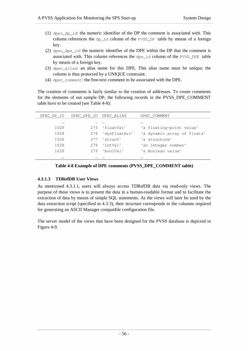
A PVSS Application for Monitoring the SPS Start-up System Design
- 56 -
(1) dpec_dp_id: the numeric identifier of the DP the comment is associated with. Thiscolumn references the dp_id column of the PVSS_DP table by means of a foreignkey.
(2) dpec_dpe_id: the numeric identifier of the DPE within the DP that the comment isassociated with. This column references the dpe_id column of the PVSS_DPE tableby means of a foreign key.
(3) dpec_alias: an alias name for this DPE. This alias name must be unique; thecolumn is thus protected by a UNIQUE constraint.
(4) dpec_comment: the free-text comment to be associated with the DPE.
The creation of comments is fairly similar to the creation of addresses. To create commentsfor the elements of out sample DP, the following records in the PVSS_DPE_COMMENTtable have to be created (see Table 4-8):
DPEC_DP_ID DPEC_DPE_ID DPEC_ALIAS DPEC_COMMENT
… … … …
1028 275 ‘floatVal’ ‘a floating-point value’
1028 276 ‘dynFloatArr’ ‘a dynamic array of floats’
1028 277 ‘struct’ ‘a structure’
1028 278 ‘intVal’ ‘an integer number’
1028 279 ‘boolVal’ ‘a Boolean value’
… … … …
Table 4-8 Example of DPE comments (PVSS_DPE_COMMENT table)
4.3.1.3 TDRefDB User Views
As mentioned 4.3.1.1, users will always access TDRefDB data via read-only views. Thepurpose of these views is to present the data in a human-readable format and to facilitate theextraction of data by means of simple SQL statements. As the views will later be used by thedata extraction script (specified in 4.3.3), their structure corresponds to the columns requiredfor generating an ASCII Manager compatible configuration file.
The server model of the views that have been designed for the PVSS database is depicted inFigure 4-9.

A PVSS Application for Monitoring the SPS Start-up System Design
- 57 -
Figure 4-9 Server model of TDRefDB user views
The views exclusively access the tables described in the previous section and follow thenaming conventions explained in 4.3.1.1.
The VPVSS_DPT view lists the records of the PVSS_DPT table’s content, hiding the surrogatekey and the comment column as they are not needed for data extraction.
The VPVSS_DPE view basically corresponds to the PVSS_DPE table (columns dpe_name anddpe_type). In addition, it contains the following columns:
• dpt_name represents name of the DPT that the DPE belongs to. To obtain thisinformation, a join with the PVSS_DPT table is necessary.
• dpt_level represents the level of hierarchy of the DPE. The level of hierarchy is 1for DPEs that are directly associated with a DPT, 2 for DPEs whose parent is a first-level DPE, etc.
• dpe_reftype references to another DPT. To obtain this information, a join with thePVSS_DPE_TYPEREF table is necessary. This feature will not be used for the SPSRestart Application.
The VPVSS_DP view corresponds to the PVSS_DP table. The values for the dpt_namecolumn will be obtained via a join with the PVSS_DPT table.

A PVSS Application for Monitoring the SPS Start-up System Design
- 58 -
The VPVSS_ADDRESS view selects those columns of the PVSS_ADDRESS table representingattributes of the _address config. Joins with PVSS_DPT, PVSS_DP and PVSS_DPE arenecessary to populate the dpt_name, dp_name and dpe_full_name columns withvalues.
The structure of the VPVSS_DISTRIB view is similar to that of VPVSS_ADDRESS, apart fromthe fact that it only selects columns representing attributes of the _distrib config fromPVSS_ADDRESS.
4.3.2 Data Import in the TDRefDB
This section will explain how existing data will be imported in the TDRefDB table structuredescribed in section 4.3.1.2. First of all, an overview of the overall data loading will bepresented in the ensuing section.
4.3.2.1 Overview of the Data Import Strategy
We have already defined and created a database structure that is suitable for storing PVSSconfiguration data. In order to fill this structure, the existing configuration information needsto be analysed and processed. As there are three distinct sources of data, three differentapproaches to integrate the data in the TDRefDB have to be elaborated:
(1) TDRefDB: Information about equipment currently managed by the Technical DataServer (TDS) is already stored in TDRefDB tables. The records concerned only needto be converted and introduced into the new table structure. Oracle Stored Proceduresimplemented in PL/SQL (see [Feuerstein, 1996]) will be used for this purpose.
(2) Configuration files: Information about electrical equipment accessed via SL-Equipis currently stored in ASCII configuration files. The data contained in these filesneeds to be analysed, validated, corrected and introduced in the TDRefDB. Thissequence of tasks will be performed by means of Perl scripts.
(3) Paper files: Some configuration information, e. g. concerning vacuum equipmentmanaged by SL-Equip, is not available electronically yet. It has to be entered in theTDRefDB manually. Alternatively, the information can also be entered in SL-Equipconfiguration files and injected in the database by means of the script mentioned in(2).
As soon as steps (1), (2) and (3) will be completed, we can start thinking about extracting thedata from the database:
(4) The well-defined configuration data will be extracted from the TDRefDB by meansof an SQL script that will generate an ASCII text file, ready to be injected to PVSSby means of the ASCII Manager.
Figure 4-10 integrates the information given above and presents an overview of the dataloading strategy.

A PVSS Application for Monitoring the SPS Start-up System Design
- 59 -
Oth
er D
ata
that
is n
ow
ava
ilab
le in
ele
ctro
nic
fo
rmat
(file
s, d
atab
ase
etc.
)
Electrical Equipment (old configuration files)
TDS Data (already stored in the TDRefDB)
TDRefDB.PVSS(Oracle)
SQLScript PVSS.DB
(Raimer)
manualchanges
script
TDRefDB.TDS(Oracle)
BA1-
...
configfile
ASCIIManager
Figure 4-10 Overview of the data loading strategy
First, a method for importing TDS configuration data already contained in the TDRefDB willbe described (4.3.2.1). Then, a strategy for introducing SL-Equip configuration data currentlystored in ASCII text files will be developed (4.3.2.3). Finally, the way additionalconfiguration data that is not available electronically yet will be integrated.
4.3.2.2 Import of TDS Configuration Data
As mentioned above, TDS configuration data is already stored in the TDRefDB. A viewcontaining all TDS data to be imported in the new table structure was created by the ST/MOdatabase experts in order to facilitate the integration process. The structure of the view isdepicted in Figure 4-11.
Figure 4-11 Server model of the VPTS_PVSS view

A PVSS Application for Monitoring the SPS Start-up System Design
- 60 -
From the data contained in this view, the PVSS_DPT, PVSS_DPE, PVSS_DP,PVSS_DPE_COMMENT and PVSS_ADDRESS tables have to be filled. This is not a trivial task asthe view does not contain all the information required and its structure does not at allcorrespond to the structure of our database.
First of all, we try to map the columns of VPTS_PVSS to the new database structure. Such amapping is presented in Table 4-9 (VPTS_PVSS columns that are irrelevant to the data importhave been omitted).
VPT_PVSSColumn
PVSS Database column Comment
dptname PVSS_DPT.dpt_name One PVSS_DPT record has to be created for eachdistinct dptname.
dpname PVSS_DP.dp_name One PVSS_DP record has to be created for eachdistinct dpname.
dpdesc PVSS_DP.dp_comment The dp_comment column will be taken intoaccount when creating the PVSS_DP records.
attrname PVSS_DPE.dpe_name One PVSS_DPE record has to be created for eachdistinct combination of dptname and attrname.Additional DPEs need to be created if theaddrmode column equals ‘O’.
addrref PVSS_ADDRESS.
addr_reference
One PVSS_ADDRESS record has to be created foreach distinct address reference (addrref).
addrmode - The addrmode, which can be ‘I’ for input or ‘O’for output must be taken into account whencreating PVSS_DPE and PVSS_ADDRESS records.
attrdesc PVSS_DPE_COMMENT.
dpec_comment
One PVSS_DPE_COMMENT record will be createdfor each distinct combination of dpname andattrname where the attrdesc column is notNULL.
Table 4-9 Mapping between the VPTS_PVSS view and the described database structure
The following subsections specify how each of the tables in the new database structure will bepopulated with records from VPTS_PVSS.
4.3.2.2.1 Data Point Types (PVSS_DPT)
To fill the PVSS_DPT table, it will suffice to create one record per distinct dptname in theVPTS_PVSS view. The dpe_type field will be DPEL_STRUCT (1) by default, as all TDS DPTswill have several subordinated DPEs. The dpt_comment column will simply be ‘TDS’ inorder to distinguish TDS DPTs from DPTs representing SL-Equip data structures.
4.3.2.2.2 Data Point Elements (PVSS_DPE)
Filling the PVSS_DPE table is more complex, as not all required values are available in theVPTS_PVSS table and some assumptions have to be made to fill the remaining columns. Firstof all, the value for the dpe_dpt_id has to be selected from the PVSS_DPT table, whichrequires that all TDS DPTs have been declared in the PVSS_DPT table beforehand. Thedpe_name column will correspond to values from the VPTS_PVSS.attrname column. Thevalue of the dpe_type column has to be derived from the second letter of

A PVSS Application for Monitoring the SPS Start-up System Design
- 61 -
VPTS_PVS.attrname for evaluations have shown that the dptype column in VPTS_PVSSdoes not contain accurate data types. If the second letter of attrname is ‘M’ or ‘C’, thedpe_type will be DPEL_FLOAT (22), otherwise it will be DPEL_BOOL (23). The dpe_parentcolumn will be NULL by default if the addrmode is ‘I’ (for input). If the addrmode is ‘O’(for output) several subordinated DPEs have to be created:
• TagName (DPEL_STRING)• ReportCode (DPEL_FLOAT)• ReportMessage (DPEL_STRING)
The dpe_parent of these subordinated DPEs is thus the numerical identifier (dpe_id) ofthe record to which they belong.
4.3.2.2.3 Data Points (PVSS_DP)
The PVSS_DP table only contains a list of all distinct dpname fields with their correspondingDPTs. The value to be entered in the dp_dpt_id column has to be selected from PVSS_DPTvia the dptname, which requires that all PVSS_DPT records have been created beforehand.
4.3.2.2.4 Comments relating to Data Point Elements (PVSS_DPE_COMMENT)
The VPT_PVSS.attrdesc field will serve as a basis for filling the dpec_comment columnof the PVSS_DPE_COMMENT table. As comments are attached to a precise DPE of a preciseDP, it will be necessary to retrieve the correct dp_id and dpe_id for each record to becreated. This necessitates that all DPEs and DPs have been declared in the databasebeforehand. The dpec_alias field will remain NULL by default.
4.3.2.2.5 Address and Distribution Configuration
The PVSS_ADDRESS tables will be filled on the basis of the addref column of theVPTS_PVSS view. One line in PVSS_ADDRESS will be created for each distinct addressreference. As addresses, like comments, are attached to a precise DPE of a precise DP, it willbe necessary to retrieve the correct dp_id and dpe_id for each record to be created. How theremaining columns are populated is specified in section 4.2.2 (address mapping).
The import of TDS configuration data will be performed by a set of Oracle Stored Proceduresimplemented in PL/SQL. We will come back to these procedures in the Implementationchapter (5).
4.3.2.3 Import of SL-Equip Configuration Data
SL-Equip configuration information that is currently stored in ASCII text files must also beintroduced in the TDRefDB database structure described above. Before the data can beimported, however, the configuration files need to be analysed, corrected and completed. Thefollowing section (4.3.2.3.1) will present an analysis of the SL-Equip file format. After that, astrategy to validate and correct the information contained in the existing configuration files isdescribed (4.3.2.3.2). Finally, the methods that will be used to import the data in theTDRefDB will be presented (4.3.2.3.3).

A PVSS Application for Monitoring the SPS Start-up System Design
- 62 -
4.3.2.3.1 Analysis of the SL-Equip File Format
Before the files could be processed, an analysis of the proprietary file format had to beperformed. The results of this analysis are shown in Listing 4-2, which contains an EBNFrepresentation of the grammar describing the file format’s syntax3:
file_set = { file }-;file = equipment_rec, { “NEWLINE”, equipment_rec};equipment_rec = equipment, “ “, action_list;equipment = member, “/”, family_part, “ “, family, “_”, member;action_list = { “ “, action }-;action = {letter}3;family_part = alphanum, alphanum;family = letter, { alphanum }5;member = alphanum, { alphanum }5;alphanum = digit | letter;letter = “A” | “B” | … | “Z”;digit = “0” | “1” | … | “9”;
Listing 4-2 EBNF representation of the SL-Equip configuration file format
Put another way, the file format is line-based, where each line represents one completeequipment record. An equipment record consists of an equipment name (specified in twodifferent formats) and a list of supported actions, separated by spaces. We will make use ofthis knowledge when designing an algorithm for validating the given information.
4.3.2.3.2 Validation and Correction of the Given Information
Before the configuration data can be introduced in the TDRefDB, it has to be validated,corrected and completed, for the available configuration files have not been updated for manyyears. A Perl script transforming the set of outdated configuration files into a single updatedconfiguration file will be implemented.
The algorithm to be implemented in the script will execute the following three steps:
(1) Read the set of configuration files and merge the information.(2) Validate the given address information, correct and complete it (as far as possible).(3) Export a new single configuration file that contains all the corrected SL-Equip
configuration data.
4.3.2.3.3 Insertion in the TDRefDB
The contents of the corrected SL-Equip configuration file resulting from the processingdescribed in the previous section will be introduced in the TDRefDB database structuredescribed in 4.3.1.2. Another Perl script making extensive use of the Perl Database Interface(see [Jepson et al., 2000]) will be implemented for this purpose.
3 Please note that ( expression )x stands for a “repeat the expression in parentheses exactly xtimes” and { expression }x denotes “repeat the expression in braces zero to x times”.

A PVSS Application for Monitoring the SPS Start-up System Design
- 63 -
4.3.3 Data Export From the TDRefDB to ASCII Manager File Format
All PVSS configuration data that is accessible from the TDRefDB user views described insection 4.3.1.3 needs to be extracted from the TDRefDB and exported to ASCII Managercompatible files These files will then be used for regular updates of the PVSS on-linedatabase, as illustrated in Figure 4-10. Before the script could be designed, however, the fileformat required by the ASCII Manager had to be analysed. The results of this analysis arepresented in the ensuing section.
4.3.3.1 Analysis of the ASCII Manager File Format
The ASCII Manager file format is very versatile. All configurations of DPTs, DPs andconfigs that can be created via the PVSS user interface (PARA module) can equally bedefined as ASCII files and the created automatically using the ASCII Manager. Examples ofsupported features are listed below:
• DPTs with an arbitrary number of DPEs can be defined.• PVSS supports 46 different scalar and compound data types for DPEs.• DPTs can be hierarchically structured and reference other DPTs that are then
included in the type definition.• Up to 20 different configs can be associated with DPs and DPEs.• Configs consist of 2 (_distrib) to 78 (_alert_hdl) attributes each.• Alias names and comments can be defined for each DP and each DPE.• etc.
It goes without saying that this flexibility considerably increases the file format’s complexity.As we will not need all of the features mentioned above in the course the SPS RestartApplication, we will limit the scope of our database design to the following four features:
(1) Definition of an arbitrary number of hierarchically structured DPTs.(2) Definition of DPs for the DPTs defined in step (1).(3) Definition of _address and _distribution configs for DPEs.(4) Definition of comments and alias names for DPs and DPEs.
Regardless of these limitations in scope, the table structure must be flexible enough toincorporate further _configs later. The design that is used to represent the _address and_distrib configs shall be applicable to other configs attached to DPEs in a similar manner.
Listing 4-3 describes the format of the input files required by the PVSS ASCII Manager. TheExtended Backus-Naur Form (EBNF), a syntactic metalanguage for writing down thegrammar of a context-free language ([Scowen, 1998]), was chosen to represent the syntax ofthe file format resulting from the analysis.
File = { Section }-;Section = (DPTSect | DPSect | ConfigSect | CommentSect), “\LF”;
(* Section for defining DPTs *)DPTSect = DPTHdr, {DPTLine}-;DPTHdr = “TypeName”, “\LF”;DPTLine = ( DPTName, DPEType, “\LF” ) | ( DPTName, “1”, “\LF”, {DPELine}- ) ;DPELine = “\Tab”, DPEName, DPEType, “\LF”;DPEType = (“41”, “:”, DPTReference) |

A PVSS Application for Monitoring the SPS Start-up System Design
- 64 -
SimpleDPEType | ArrayDPEType | StructureDPEType;DPTReference = DPTName;DPTName = PVSSidentifier;DPEName = PVSSidentifier;
(* Section for creating DPs of existing DPTs *)DPSect = DPHdr, { DPLine }-;DPHdr = “DpName”, “\Tab”, “TypeName”, [ “\Tab”, “ID” ], “\LF”;DPLine = DPName, “\Tab”, DPTName, [ “\Tab”, DPID ], “\LF”;DPName = PVSSidentifier;DPID = IntegerNumber;
(* Section for creating configs for existing DPs and DPEs *)ConfigSect = DistribConf | AddressConf;
(* Section for defining the attributes of the _distrib config *)DistribConf = DistribHdr, { DistribLine }-;DistribHdr = “ElementName”, ”\Tab”, “TypeName”, “\Tab”,
“_distrib.._type”, “\Tab”, “_distrib.._driver”, “\LF”;DistribLine = ElementName, “\Tab”, DPTName, “\Tab”,
DistribType, “\Tab”, “\”, DriverNum, “\LF”;ElementName = DPName, “.”, DPEName;DistribType = (“0” | “56”);DriverNum = IntegerNumber;
(* Section for defining the attributes of the _address config *)AddressConf = AddressHdr, { AddressLine }-;AddressHdr = “ElementName”, “\Tab”, “TypeName“, “\Tab”,
“_address.._type”, “\Tab”, “_address.._reference”, “\Tab”, “_address.._offset”, “\Tab”,
“_address.._subindex”, “\Tab”, “_address.._mode”, “\Tab”, “_address.._start”, “\Tab”, “_address.._interval”, “\Tab”, “_address.._reply”, “\Tab”, “_address.._datatype”, “\Tab”, “_address.._drv_ident”, “\LF”;AddressLine = ElementName, “\Tab”, DPTName, “\Tab”, IntegerNumber,
“\Tab”, DBQString, “\Tab”, IntegerNumber, “\Tab”, IntegerNumber, “\Tab”, AddressMode, “\Tab”, TimeValue, “\Tab”, TimeValue, “\Tab”, TimeValue, “\Tab”,
IntegerNumber, “\Tab”, DBQString, “\LF”.AddressMode = “\”, IntegerNumber;
(* Section for defining comments and alias names for DPs and DPEs *)CommentSect = CommentHdr, { CommentLine }-;CommentHdr = “AliasId”, “\Tab”, “AliasName”, “\Tab”,
“CommentName”, “\LF”;CommentLine = (DPName | ElementName), “\Tab” AliasName, “\Tab”, DBQString, “\LF”;AliasName = PVSSidentifier;
Listing 4-3 EBNF representation of the ASCII Manager file format
Remarks on the EBNF listed above:The terminal symbol “\LF” denotes a new line in the text file, “\Tab” denotes a tabulator. Thefollowing non-terminal symbols are not resolved in the above grammar:
• PVSSidentifier: a character string containing the name of a DPT, DP or DPE. Forrestrictions applying to PVSS identifiers, please refer to [ETM, 2000].
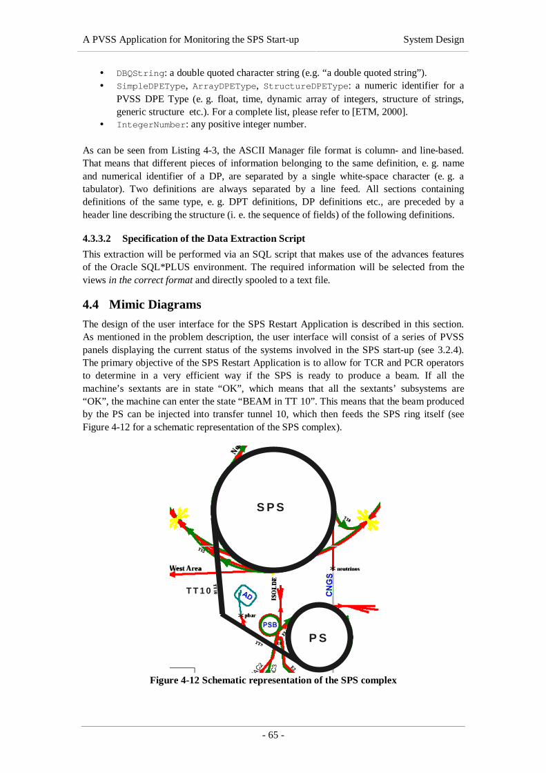
A PVSS Application for Monitoring the SPS Start-up System Design
- 65 -
• DBQString: a double quoted character string (e.g. “a double quoted string”).• SimpleDPEType, ArrayDPEType, StructureDPEType: a numeric identifier for a
PVSS DPE Type (e. g. float, time, dynamic array of integers, structure of strings,generic structure etc.). For a complete list, please refer to [ETM, 2000].
• IntegerNumber: any positive integer number.
As can be seen from Listing 4-3, the ASCII Manager file format is column- and line-based.That means that different pieces of information belonging to the same definition, e. g. nameand numerical identifier of a DP, are separated by a single white-space character (e. g. atabulator). Two definitions are always separated by a line feed. All sections containingdefinitions of the same type, e. g. DPT definitions, DP definitions etc., are preceded by aheader line describing the structure (i. e. the sequence of fields) of the following definitions.
4.3.3.2 Specification of the Data Extraction Script
This extraction will be performed via an SQL script that makes use of the advances featuresof the Oracle SQL*PLUS environment. The required information will be selected from theviews in the correct format and directly spooled to a text file.
4.4 Mimic Diagrams
The design of the user interface for the SPS Restart Application is described in this section.As mentioned in the problem description, the user interface will consist of a series of PVSSpanels displaying the current status of the systems involved in the SPS start-up (see 3.2.4).The primary objective of the SPS Restart Application is to allow for TCR and PCR operatorsto determine in a very efficient way if the SPS is ready to produce a beam. If all themachine’s sextants are in state “OK”, which means that all the sextants’ subsystems are“OK”, the machine can enter the state “BEAM in TT 10”. This means that the beam producedby the PS can be injected into transfer tunnel 10, which then feeds the SPS ring itself (seeFigure 4-12 for a schematic representation of the SPS complex).
T T 1 0
S P S
P S
Figure 4-12 Schematic representation of the SPS complex
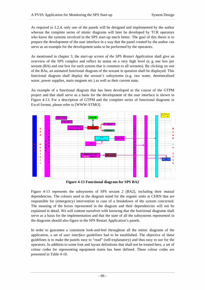
A PVSS Application for Monitoring the SPS Start-up System Design
- 66 -
As required in 3.2.4, only one of the panels will be designed and implemented by the authorwhereas the complete series of mimic diagrams will later be developed by TCR operatorswho know the systems involved in the SPS start-up much better. The goal of this thesis is toprepare the development of the user interface in a way that the panel created by the author canserve as an example for the development tasks to be performed by the operators.
As mentioned in chapter 3, the start-up screen of the SPS Restart Application shall give anoverview of the SPS complex and reflect its status on a very high level (e. g. one box persextant (BA) and one box for each system that is common to all sextants). By clicking on oneof the BAs, an animated functional diagram of the sextant in question shall be displayed. Thisfunctional diagram shall display the sextant’s subsystems (e.g. raw water, demineralisedwater, power supplies, main magnets etc.) as well as their current state.
An example of a functional diagram that has been developed in the course of the GTPMproject and that shall serve as a basis for the development of the user interface is shown inFigure 4-13. For a description of GTPM and the complete series of functional diagrams inExcel format, please refer to [WWW-STMO].
Figure 4-13 Functional diagram for SPS BA2
Figure 4-13 represents the subsystems of SPS sextant 2 (BA2), including their mutualdependencies. The colours used in the diagram stand for the organic units at CERN that areresponsible for (emergency) intervention in case of a breakdown of the system concerned.The meaning of the boxes represented in the diagram and their dependencies will not beexplained in detail. We will content ourselves with knowing that the functional diagrams shallserve as a basis for the implementation and that the state of all the subsystems represented inthe diagrams should also figure in the SPS Restart Application’s panels.
In order to guarantee a consistent look-and-feel throughout all the mimic diagrams of theapplication, a set of user interface guidelines had to be established. The objective of theseguidelines is to make the panels easy to “read” (self-explanatory) and thus easy to use for theoperators. In addition to some font and layout definitions that shall not be treated here, a set ofcolour codes for representing equipment states has been defined. These colour codes arepresented in Table 4-10.

A PVSS Application for Monitoring the SPS Start-up System Design
- 67 -
State Colour DescriptionST_OK green The system in question is OK and switched on. It is thus
working normally.ST_OFF white The system in question is OK but switched off. It is thus
inactive for the moment.ST_WARNING yellow The system has a problem (e. g. a critical temperature has
been reached) but is still working.ST_FAULT red The system in question is in a bad state and not working
any more.ST_NO_DATA blue The current state of the system cannot be determined
(e.g. due to a hardware, transmission or driver problem).ST_INHIBITED grey The equipment is out of service (e.g. for maintenance).ST_NOT_ANIMATED dark grey
Table 4-10 Definition of system states and colour codes
The most essential and at the same time most difficult task during the panel design was toanalyse and understand how the states of all the subsystems can be determined. First, allhardware elements related to a subsystem (e.g. voltmeters, breakers etc.) had to be identifiedin co-operation with TCR operators. Second, the PVSS DPE representing these hardwareelements had to be determined and finally, a set of conditions had to be defined for eachsubsystem in order to find out whether the system is OK, OFF, FAULTY etc.
An example of such an analysis will be given in section 5.4 of the following chapter, wherethe implementation of the user interface panel is explained.

A PVSS Application for Monitoring the SPS Start-up Implementation
- 68 -
5. IMPLEMENTATIONFollowing the software project lifecycle, this chapter describes the technical details of theproject’s implementation, based on the results of the detailed design presented in chapter 4.
5.1 System Architecture
The PVSS system for the SPS Restart Application was implemented exactly as specified inchapter 4.1. No additional software development was required for the system’s set-up apartfrom the modification of several operating system settings and the adaptation of PVSSconfiguration files. How PVSS is installed in a redundant and distributed way is welldocumented in [ETM, 2000] and shall not be treated here. All the same, we want tosummarise the tasks that had to be performed for the implementation of the PVSS core systemon the redundant Linux servers and for the installation of a PVSS user interface on aWindows NT Workstation. Figure 5-1 gives an overview of the whole PVSS systemimplemented for the SPS Restart Application.
subdbst1.cern.ch lnxoptim2.cern.ch
lnxoptim1.cern.ch
PVSS
st_tsi
Event Data
Ctrl
To hardwarevia SL-Equip
Oracleclient
To hardwarevia TDS
ASCII
Libraries (SL-Equip,Xdal, SmartSockets)
Redhat Linux 6.1 (CERN edition)
TDSSLE
Dist
Redu
NFSclient
TDRefDB(Oracle
database)
pcst291.cern.ch
PVSS
cernhome08.cern.ch
File server
PVSSconfigfiles
PVSSpanel &scriptfiles
PVSSconfigfiles
Windows NT/2000(NICE)
To distributionpartner(s)
PVSSconfigfiles
config datadef. file
Operators’ Workstations
PVSSRedundancy
Partner
implemented likelnxoptim1.cern.ch
UIM
Oracle StoredProcedures
Figure 5-1 Overview of the PVSS system’s implementation
A PVSS Application for Monitoring the SPS Start-up Implementation
- 69 -
Figure 5-1 is a synopsis of Figure 4-1 and Figure 4-2 of the System Design chapter,complemented by the names of the servers and by the software parts and configuration filesthat had to be installed on each of the computers. The machines represented by boxes havebeen modified by the author whereas machines represented by pictograms have been used“as-is” – as external systems.
5.1.1 Set-up of the Redundant Linux Servers
This section presents a list of all tasks that had to be performed to make the core PVSSsystem for the SPS Restart Application run, as specified in 4.1.4. Both Linux servers,lnxoptim1 and lnxoptim2, have been configured identically.
5.1.1.1 Additional Hardware Installation
In addition to the hardware specified in section 4.1.4, the following components had to beinstalled:
• Two 100 MBit network adapters on each of the servers.• A direct connection between the two servers.• A connection to the CERN network for each of the servers.
5.1.1.2 Software Installation
• Installation of Redhat Linux 6.1, including CERN-specific packages (see [WWW-CERNLNX]).
• Installation of PVSS II 2.11.1 (see [ETM, 2000]).• Installation of the libraries required by the TDS and SL-Equip drivers (i. e. SL-Equip,
Xdal and Talarian SmartSockets®).• Installation of the TDS Driver Manager developed at CERN.• Installation of the SL-Equip Driver Manager developed in the course of the SPS
Restart Application project (see section 5.2).• Installation of the database loader script specified in section 5.3.
5.1.1.3 Software Configuration
• Creation of a user account for the PVSS project.• Creation of a PVSS project (called st_tsi) in the PVSS user’s home directory.• Modification of the project’s configuration files to activate redundancy and
distribution features. Relevant parts of the configuration files concerned are listed inAppendix A.
• Creation of NFS mount points for the project directories of the redundancy partners(lnxoptim1 mount lnxoptim2 and vice versa). These remote directories will be usedfor synchronising with the on-line database of the redundancy partner on start-up.
• Modification of the shell environment of the PVSS user (activation of Oracle networkinstallation, setting of PVSS-specific environment variables, paths etc.)
• Extraction of static configuration data from the TDRefDB (by means of the databaseloader script described in section 5.3.).
• Injection of static configuration data (DPT, DP, DPE and config definitions) in PVSSby means of the PVSS ASCII Manager.
5.1.2 Set-up of the Windows NT Workstations
The set-up of the NT Workstations for running the PVSS user interface was much simpler.No additional hardware was required. The following task list is based on the assumption that

A PVSS Application for Monitoring the SPS Start-up Implementation
- 70 -
the PVSS user interface project is set up on a workstation with a standard CERN WindowsNT 4.0 installation (including network access).
5.1.2.1 Software Installation
• Installation of PVSS II 2.11.1 (see [ETM, 2000]).
5.1.2.2 Software Configuration
• Mounting (mapping) of the file server’s network share containing PVSS panels,scripts etc.
• Creation of a PVSS II user interface project (see [WWW-ITCO]).• Modification of the project’s configuration files to load panels and scripts from the
file server and to connect to the redundant PVSS servers.
5.2 Driver Implementation
This section covers the implementation of the PVSS Driver Manager to SL-Equip as specifiedin section 4.2. Class design and run-time behaviour (object design) of the driver have beendescribed in the System Design chapter; we only concentrate on implementation issues thathave not been treated in sufficient detail. Some interesting details of the implementation arehighlighted, e.g. how UNIX signals are used for debugging purposes, how a connection toSL-Equip is established and how the driver’s internal DP lists are managed.
5.2.1 Implementation Constraints
The SL-Equip driver has been implemented in C/C++, using the PVSS and SL-EquipApplication Programming Interfaces (APIs). Wind River’s SNiFF+™ tool, an IntegratedDevelopment Environment (IDE) for C, C++, Java, Fortran and CORBA IDL, was chosen forsource code editing, for it is one of the most powerful IDEs available on Linux. One of theLinux servers described in the previous section was used as a development machine in orderto guarantee that the driver is developed and tested in the same environment in which it willlater become operational. The driver was compiled and linked with the Gnu C++ compiler(g++), using the standard UNIX make tool rather than the make utility provided by Sniff.The C++ programming and documentation guidelines provided by ETM ([WWW-ITCO]),which have been developed for the implementation of the PVSS API, have equally beenapplied for the development of the SL-Equip driver.
Doc++, a documentation system for C/C++ and Java generating both, LaTeX output for highquality hardcopies and HTML output for online browsing (see [WWW-DOC++]), has beenused for automatically generating a system documentation for the SL-Equip driver. Thedocumentation was extracted from special JavaDoc-style comments in the C++ header files.
5.2.2 Implementation of the Classes
The structure of this section corresponds to the structure of the classes required for theimplementation (see 4.2.3), starting with the driver’s core class: SleDriver.
5.2.2.1 SleDriver
As mentioned in 4.2.3.1.1, the SL-Equip Driver Manager (SleDriver) class is the heart of thedriver, managing the control flow of the process as well as the connection to PVSS and to theperiphery.

A PVSS Application for Monitoring the SPS Start-up Implementation
- 71 -
The implementation of the install_HWService(), install_HWMapper() andgetHWObject() methods is obvious from their specification. We will thus concentrate onthe signalHandler() method that handles two signals received from the operating system:
• SIGTERM (15) is received when the driver is supposed to terminate.• SIGHUP (1) is received in case of a hang-up of the controlling terminal. As the SL-
Equip driver will run as a background process, there is no need to handle SIGHUP.The signal has thus been redefined as a “SIGDEBUG” that causes the driver to switchon/off debug messages.
How the signal handler was implemented is shown in Listing 5-1. When SIGTERM isreceived, the driver’s internal mode is set to DRVMODE_EXITING, which causes themainLoop() method to exit and the driver to close down all its connections before itterminates, as described in 4.2.4.3. When SIGHUP is received, the switchDbgLevel()method of the SleResources class is called. This method changes the value of theResources::dbgLevel class variable that is checked each time before debug messages areissued. This feature is very practical, for the user can switch on/off debugging by sending akill –1 to the process from the command line, without having to stop/restart the driver. Asa consequence, the current process image is not lost and the debug messages written to thedriver’s log file perfectly reflect the situation that has lead to a problem. All other signals arehandled by the super class of SleDriver.
#include <signal.h>
jmp_buf SleDriver::jumpBuf;
void SleDriver::signalHandler( int signal ) { switch (signal) { case SIGHUP: SleResources::switchDbgLevel(); cerr << "Debug mode " << (Resources::getDbgLevel() ? "ENABLED." : "DISABLED.") << endl; break; case SIGTERM: cerr << "exiting - please wait ..."; internalMode = DRVMODE_EXITING; longjmp(jumpBuf, 1); break; default: DrvManager::signalHandler(signal); } // switch} // signalHandler()
Listing 5-1 Implementation of the signalHandler method (SleDriver class)
5.2.2.2 SleResources
As specified in section 4.2.3.3.2, the SleResources class manages static driver configurationinformation. Its methods read driver-specific sections of the PVSS configuration file and storeits content in static class variables.
As the SL-Equip driver does not need any additional information from the configuration file,the methods begin() and readSection() contain a dummy implementation. Hence, the

A PVSS Application for Monitoring the SPS Start-up Implementation
- 72 -
methods of interest are those that are used for the implementation of the debuggingmechanism mentioned in the previous section:
• The end() method is supposed to override configuration options specified ascommand line parameters. Since the SL-Equip driver does not need to override anyof these options, it simply calls the end() method of the super class (DrvRsrce).Subsequently, the currently set debug level (dbgLevel) is read out and an additionalclass attribute (SleResources::saveSwitchDbgLevel) is set depending on thisvalue. If debugging is active (dbgLevel > 0), the saveSwitchDbgLevel attributeis set 0, otherwise 1. The saveSwitchDbgLevel variable is used to toggledebugging on/off in the switchDbgLevel method.
• The setDbgLevel() method sets the driver’s internal debug level by assigning apositive integer value to the Resources::dbgLevel class member.
• The switchDbgLevel() method exchanges the current value of the dbgLevelvariable with the value of saveSwitchDbgLevel (toggle functionality). The methodis called by the handler for SIGHUP, as described in the previous section.
The code of the three methods described above is listed in Listing 5-2. Commands forgenerating debug output and some comments have been removed for reasons of brevity.
unsigned long SleResources::saveSwitchDbgLevel;
/** Initialise saveSwitchDbgLevel variable according to the * debug level specified on the command line (dbgLevel). */void SleResources::end(int &argc, char *argv[]) { DrvRsrce::end(argc,argv); if (Resources::getDbgLevel()) SleResources::saveSwitchDbgLevel = 0; else SleResources::saveSwitchDbgLevel = Resources::getDbgLevel();}
/** Set the specified debug level. * @param level debug level to be set (integer >= 0) */static void SleResources::setDbgLevel(unsigned long level) { if (level > 0) Resources::dbgLevel = level; else Resources::dbgLevel = 0;}
/** Toggle debugging on/off */static void SleResources:: switchDbgLevel () { unsigned long oldLevel = Resources::dbgLevel; setDbgLevel (SleResources::saveSwitchDbgLevel); SleResources::saveSwitchDbgLevel = oldLevel;}
Listing 5-2 Implementation of the switchDbgLevel method (SleResources class).
5.2.2.3 SleMapper
As the name implies, the SleMapper class performs the mapping (1) between PVSS DPidentifiers and peripheral addresses (PeriphAddr) and (2) between peripheral addresses and

A PVSS Application for Monitoring the SPS Start-up Implementation
- 73 -
SL-Equip Hardware Objects (SleMapObj). As specified in 4.2.3.1.3, its most essential task isto add/remove peripheral addresses to/from the internal lists managed by the HWMappersuper class. This task is performed by the addDpPa() and clrDpPa() methods with theinterfaces listed below:
PVSSboolean SleMapper::addDpPa(DpIdentifier &dpId, PeriphAddr *confPtr)
PVSSboolean SleMapper::clrDpPa(DpIdentifier &dpId, PeriphAddr *confPtr)
The clrDpPa() method tries to find the hardware object (SleMapObj) corresponding to theperipheral address it receives as a parameter by means of a tool function provided by the baseclass. If such an object is found, it is removed from the internal list of hardware objects bymeans of a call to the clrHWObject() of the HWMapper class. Subsequently, theclrDpPa() method of the base class is called in order to remove the peripheral address fromthe internal list as well.
The addDpPa() method is fairly more complicated; its code is listed in Listing 5-3. First ofall, an appropriate Transformation has to be assigned to the PeriphAddr object received as aparameter. The Transformation subclass to be instantiated is determined in accordance withthe transformation type of the peripheral address, which was specified by the user during theconfiguration of the _address config (see 4.2.3.1.3). The fully configured PeriphAddr objectis then added to an internal list by a call to the addDpPa method of the super class. If thisoperation succeeds, a new SleMapObj is created and filled with information contained in theperipheral address (address string, transformation type, data length etc.). The fully configuredhardware object is also added to an internal list by a call to the addHWObject() methodprovided by the super class. If all described steps are successful, PVSS_TRUE is returned,otherwise the method returns PVSS_FALSE.
PVSSboolean SleMapper::addDpPa(DpIdentifier &dpId, PeriphAddr*confPtr) { // Set the appropriate transformation type for the config switch (confPtr->getTransformationType()) { case SleTransIntType : confPtr->setTransform(new SleTransInt); break; case SleTransStringType : confPtr->setTransform(new SleTransString); break; case SleTransFloatType : confPtr->setTransform(new SleTransFloat); break; default : // Error handling for types that are not handled by the driver ErrHdl::error( ErrClass::PRIO_SEVERE, // Severe error ErrClass::ERR_PARAM, // It was a wrong type ErrClass::UNEXPECTEDSTATE, // Never expect "SleMapper", "addDpPa", // Class and method CharString("Illegal transformation type ") + CharString( (int) confPtr->getTransformationType()) ); if (!confPtr->getName) return PVSS_FALSE; confPtr->setTransform(new Transformation()); // Although there was an error add the config to the list // but don’t create a HWObject for it.

A PVSS Application for Monitoring the SPS Start-up Implementation
- 74 -
return HWMapper::addDpPa(dpId, confPtr); } // Call the addDpPa method of the super class, which adds the fully // configured PeriphAddr object to its internal list. if (!HWMapper::addDpPa(dpId, confPtr)) return PVSS_FALSE;
// Create a new SleMapObj for the given PeriphAddr. SleMapObj* objPtr= new SleMapObj(confPtr); // Set address and subindex appropriately objPtr->setAddress(confPtr->getName()); objPtr->setSubindex(confPtr->getSubindex()); objPtr->setType(confPtr->getTransform()->isA()); objPtr->setDlen(confPtr->getTransform()->itemSize()); // add the new SleMapObj to the list addHWObject(objPtr);
return PVSS_TRUE;} // addDpPa
Listing 5-3 Implementation of the addDpPa method (SleMapper class)
The implementation of the actualize() method is very similar to that of addDpPa(). It iscalled if a change in the peripheral address is triggered by the hardware, which will never bethe case for the SL-Equip driver.
5.2.2.4 SleMapObj
The SleMapObj class was implemented following its specification in 4.2.3.3.1. As it mainlyconsists of setXXX() and getXXX() methods for reading and writing the differentcomponents of an SL-Equip address (specified in 2.3.2 and 4.2.2), we will not treat it in moredetail here.
5.2.2.5 SleSrvHdl
As specified in 4.2.3.1.2, the SL-Equip Service Handler (SleSrvHdl) class handles read andwrite requests to the SL-Equip middleware. The singleQuery() and writeData()methods – the final links in the data acquisition and command chain of the driver – had to beoverwritten for this purpose.
The framework calls the singleQuery() method whenever the value of a peripheral addressneeds to be polled from SL-Equip (e. g. when the polling time for a particular DPE has beenreached). The peripheral address of the DPE to be retrieved is packed into a HWObject by theframework and then passed to the singleQuery() method as an input parameter. ThesingleQuery() method first finds the SleMapObj corresponding to the HWObject receivedfrom the SleMapper’s internal list. The SL-Equip address information contained in this objectis then extracted and some SL-Equip variables (name of equipment host, timeout etc.) are set.The address information is packed into an SL-Equip client call (EQUIP() function) that issupposed to acquire the desired value from the hardware. If the client call is successful, thereceived data is packed into a new SleMapObj and communicated to PVSS via a call to thetoDp() method of the SleDriver class. In return, the SleDriver calls the toVar() method ofthe Transformation object associated with the SleMapObj and finally communicates the newvalue to the Event Manager. If the client call fails and SL-Equip returns an error code, theerror number is converted into a binary representation and the status bits of the SleMapObjare set accordingly. Also in this case, the toDp() method is invoked in order to communicatethe error information to the Event Manager and, as a consequence, to the user.

A PVSS Application for Monitoring the SPS Start-up Implementation
- 75 -
The writeData() method does exactly the opposite of singleQuery(), writing changedvalues to SL-Equip and transmitting them to the equipment in the field. The logicimplemented in the function is still very similar, as the EQUIP() function provided by the SL-Equip API works in both directions, for sending as well as receiving data. Naturally, no valueis transmitted to PVSS as a result of the action.
The C++ code for the singleQuery() and writeData() methods is listed in Appendix B.
5.2.2.6 SleTransXXX
Derived from the general Transformation class provided by the PVSS API, the SleTransXXXclasses are used for any transformation from SL-Equip values to PVSS DPE values and viceversa. The functionality of these classes’ methods is specified in chapter 4.2.3.2. We takeSleTransFloat as an example to describe the implementation of a transformation; SleTransIntand SleTransString have been implemented analogously.
The itemSize() method returns the size in bytes of a single value of the type to betransformed. For SleTransFloat objects, the itemSize() method returns 8.
The toPeriph() method is used for converting data in the command direction. The driverframework writes the data to be transformed into a Variable object and passes it to themethod as an input parameter, together with the length of the data and, eventually, a sub-index designating the position of the element within a dynamic array. Furthermore, theframework allocates a buffer in which the toPeriph() method is supposed to write thetransformed value (output parameter). toPeriph() first checks if the type of the Variableobject received is either FLOAT_VAR (for floating-point values) or DYN_VAR (for dynamicarrays). If the type is FLOAT_VAR, the value is directly copied into the right position of theoutput buffer, which is calculated from the sub-index and the itemSize (buffer +
subindex * itemsize()). If the variable type is DYN_VAR, each of the array’s elementshas to be processed separately. All elements (which are expected to be of type FLOAT_VAR)are extracted and transformed in recursive calls to toPeriph(). The method returnsPVSS_TRUE if the transformation is successful.
PVSSboolean SleTransFloat::toPeriph(PVSSchar *buffer, PVSSuint len , const Variable &var, const PVSSuint subix) const
{ // Be paranoiac, check variable type if (var.isDynVar()) { const Variable *varPtr = 0; int i = 0; for (varPtr = ((const DynVar &) var).getFirstVar(); varPtr = ((const DynVar &) var).getNextVar(); i++) { // call yourself recursively if (! toPeriph(buffer, len, *varPtr, subix+i)) return PVSS_FALSE; } // for } // if // Single float (in reality: double) value else if (var.isA() == FLOAT_VAR) { // Check if subindex and data length (len) match Å avoid // overwriting the end of the buffer if ( len > subix * itemSize() ) { double d = ((FloatVar&) var).getValue();

A PVSS Application for Monitoring the SPS Start-up Implementation
- 76 -
memcpy( &buffer[subix * itemSize()], &d, itemSize() ); } // if else { // Data length was incorrect ErrHdl::error( ErrClass::PRIO_SEVERE, // Data will be lost ErrClass::ERR_PARAM, // Wrong parameterisation ErrClass::UNEXPECTEDSTATE, // Never expect "SleTransFloat", "toPeriph", // File and function name "Wrong variable length for data" // don’t know DP ); return PVSS_FALSE; } // else } // else else { ErrHdl::error( ErrClass::PRIO_SEVERE, // Data will be lost ErrClass::ERR_PARAM, // Wrong parametrization ErrClass::UNEXPECTEDSTATE, "SleTransFloat", "toPeriph", // File and function name "Wrong variable type for data" // don’t know DP ); return PVSS_FALSE; } // else // Everything OK return PVSS_TRUE;}
Listing 5-4 Implementation of the toPeriph method (SleTransFloat class)
The toVar() method is used for transforming values obtained from SL-Equip to PVSSvariables; it is thus the counterpart to the toPeriph() method. A buffer containing the datato be transformed, the size of the buffer and a sub-index are passed to the method as inputparameters. First, it has to be ensured that the given sub-index, multiplied by itemSize(),does not exceed the size of the input buffer, which would inevitably lead to an exception. Ifthe input parameters are correct, the value is copied into a FloatVar variable which is thenreturned to the caller. If the input parameters are incorrect, the method returns NULL.
Finally, the isA() method returns the TransformationType represented by the class,i. e. SleTransFloatType.
As mentioned above, the implementation of SleTransInt and SleTransString is very similar,apart from the fact that SleTransString does not support dynamic arrays. Contrary to floats orintegers, the length of a string (i. e. its itemSize()) cannot be determined in advance.
5.2.3 Implementation of the Driver Configuration Panel
In order to configure the DPEs to be retrieved by the SL-Equip driver conveniently via thePVSS user interface, a new panel had to be created. Thanks to a PVSS naming convention,this panel is integrated into the PVSS parameterisation module and displayed as soon as the_address config of a DPE connected to the SL-Equip driver is modified.
A screenshot of the panel implemented for the SL-Equip driver is shown in Figure 5-2. Theleft part of the screenshot shows the DP hierarchy browser of the PVSS PARA module whilethe right part shows the parameterisation panel described in this section. In the left upper partof the panel, SL-Equip address information (consisting of family, member, host action and
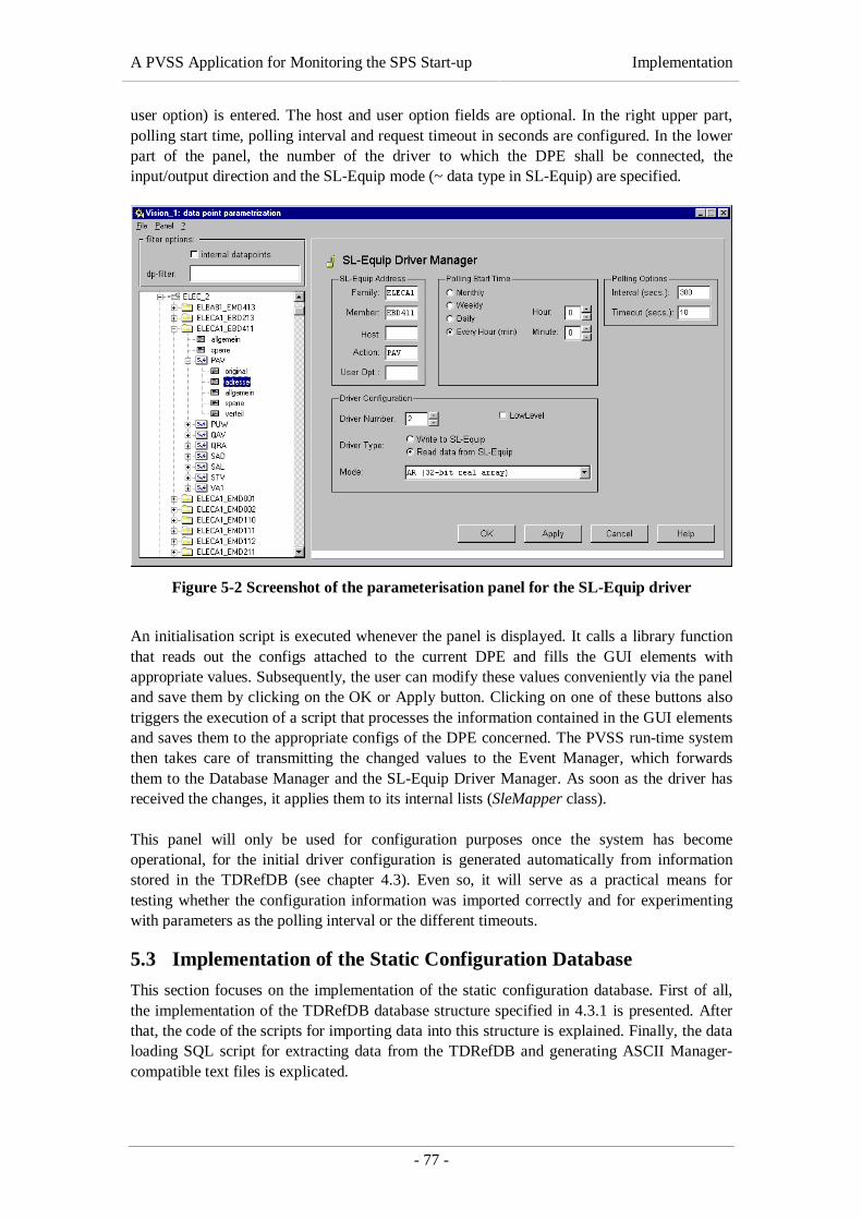
A PVSS Application for Monitoring the SPS Start-up Implementation
- 77 -
user option) is entered. The host and user option fields are optional. In the right upper part,polling start time, polling interval and request timeout in seconds are configured. In the lowerpart of the panel, the number of the driver to which the DPE shall be connected, theinput/output direction and the SL-Equip mode (~ data type in SL-Equip) are specified.
Figure 5-2 Screenshot of the parameterisation panel for the SL-Equip driver
An initialisation script is executed whenever the panel is displayed. It calls a library functionthat reads out the configs attached to the current DPE and fills the GUI elements withappropriate values. Subsequently, the user can modify these values conveniently via the paneland save them by clicking on the OK or Apply button. Clicking on one of these buttons alsotriggers the execution of a script that processes the information contained in the GUI elementsand saves them to the appropriate configs of the DPE concerned. The PVSS run-time systemthen takes care of transmitting the changed values to the Event Manager, which forwardsthem to the Database Manager and the SL-Equip Driver Manager. As soon as the driver hasreceived the changes, it applies them to its internal lists (SleMapper class).
This panel will only be used for configuration purposes once the system has becomeoperational, for the initial driver configuration is generated automatically from informationstored in the TDRefDB (see chapter 4.3). Even so, it will serve as a practical means fortesting whether the configuration information was imported correctly and for experimentingwith parameters as the polling interval or the different timeouts.
5.3 Implementation of the Static Configuration Database
This section focuses on the implementation of the static configuration database. First of all,the implementation of the TDRefDB database structure specified in 4.3.1 is presented. Afterthat, the code of the scripts for importing data into this structure is explained. Finally, the dataloading SQL script for extracting data from the TDRefDB and generating ASCII Manager-compatible text files is explicated.

A PVSS Application for Monitoring the SPS Start-up Implementation
- 78 -
5.3.1 TDRefDB Database Structure
For the implementation of the TDRefDB structure described in chapter 4.3.1 (DatabaseDesign), the creation of the tables containing the data (4.3.1.2) and the creation of the userviews (4.3.1.3) have to be distinguished.
5.3.1.1 TDRefDB Tables
The TDRefDB table structure was generated automatically from the server model diagramdepicted in Figure 4-8. The diagram was created using Oracle Designer® 2000, a powerfulCASE tool for database design that supports the automatic generation of database schematafrom so-called server models. A re-engineering option, called design capturing, allows thegeneration of server model diagrams from existing database structures. This inverse approachwas chosen for creating the server model diagram of the user views described in the ensuingsection.
5.3.1.2 TDRefDB User Views
The user views depicted in Figure 4-9 were created manually, by means of an SQL script. TheSELECT statements for assembling the data contained in the views are rather complex,including multiple joins, subqueries and meta columns. This is why tool-supported generationwould not have facilitated the task of view creation. So, only the reverse-engineering optionof Designer 2000 was used to create the server model diagram depicted in Figure 4-9.
We illustrate the view creation process by means of an example, the VPVSS_DPT andVPVSS_DPE views. As mentioned in 4.3.1.3, DPTs are declared in VPSS_DPT and theirhierarchical structure of DPEs is defined in PVSS_DPE. The SELECT statements used forcreating the views are listed in Listing 5-5.
CREATE OR REPLACE VIEW vpvss_dpt AS SELECT dpt_name, dpt_type, dpt_comment FROM pvss_dpt ORDER BY dpt_name;
CREATE OR REPLACE VIEW VPVSS_DPE( dpt_name, dpe_level, dpe_name, dpe_type, dpe_reftype)AS SELECT dpt.dpt_name, dpe_level, dpe_name, dpe_type, dpt2.dpt_name FROM ( -- hierarchical subquery as one of the data sources SELECT dpe_dpt_id, dpe_id, level dpe_level, dpe_name, dpe_type FROM pvss_dpe START WITH dpe_id IN (
SELECT dpe_id FROM pvss_dpe WHERE dpe_parent IS NULL ) CONNECT BY PRIOR dpe_id = dpe_parent ) dpe, pvss_dpt dpt, pvss_dpe_typeref dpet, pvss_dpt dpt2 WHERE dpt.dpt_id = dpe.dpe_dpt_id AND dpe.dpe_id = dpet.dpet_dpe_id (+) AND dpet.dpet_dpt_ref = dpt2.dpt_id (+) ORDER BY dpt_name;
Listing 5-5 Statements for creating the VPVSS_DPT and VPVSS_DPE views (SQL)
A PVSS Application for Monitoring the SPS Start-up Implementation
- 79 -
The statement for creating the VPVSS_DPT view only selects three columns of the PVSS_DPTtable and sorts the results by dpt_name.
The definition of the VPVSS_DPE view is far more complex. First of all, it contains data fromfour different sources:
• PVSS_DPT is used twice: once for selecting the name of the DPT associated with theDPE described by the record and once for selecting the name of a DPT that couldeventually be referenced the DPE.
• PVSS_DPE_TYPEREF is used to find the identifier of DPTs that are referenced by oneor more DPEs.
• A hierarchical subquery presents the columns of PVSS_DPE in a different format andincludes the level of hierarchy for each DPE.
These four sources require the definition of three join criteria:
• PVSS_DPT (dpt1 in the statement above) and PVSS_DPE are joined by an innerjoin on the DPT identifier.
• PVSS_DPE and PVSS_DPE_TYPREF are joined by a right outer join on the DPEidentifier.
• PVSS_DPE_TYPREF and PVSS_DPT (dpt2 in the statement above) are joined by aright outer join on the identifier of the referenced DPT.
Finally, the returned records are ordered by dpt_name.
We illustrate the abstract description given above by an example, falling back on our sampleDPT TypeA, defined in section 4.3.1.2.2. A query for all elements of TypeA would return thefollowing result:
DPT_NAME DPE_LEVEL DPE_NAME DPE_TYPE DPE_TYPREFF
‘TypeA’ 1 ‘aFloat’ 22 NULL
‘TypeA’ 1 ‘aDFloat’ 6 NULL
‘TypeA’ 1 ‘aStruct’ 1 NULL
‘TypeA’ 2 ‘anInt’ 21 NULL
‘TypeA’ 2 ‘aBool 23 NULL
Table 5-1 Example of a DPT definition in VPVSS_DPE
The SQL statements for creating the remaining four views (VPVSS_DP, VPVSS_ADDRESS,VPVSS_DISTRIB and VPVSS_DPE_COMMENT) are not discussed in detail.
5.3.2 Import of Existing Configuration Information in the TDRefDB
This section describes the implementation of the data import scripts and procedures specifiedin chapter 4.3.2.3. First, the implementation of the PL/SQL procedures for importing TDSconfiguration information is explained. Thereafter, the implementation of the Perl scripts forimporting the contents of SL-Equip configuration files is dealt with.
5.3.2.1 Implementation of PL/SQL Procedures for Importing TDS Configuration Data
This section describes the implementation of the import strategy for static TDS configurationdata as specified in chapter 4.3.2. As mentioned above, PL/SQL, Oracle’s procedural

A PVSS Application for Monitoring the SPS Start-up Implementation
- 80 -
language (PL) superset of the structured query language (SQL) [Koch and Loney, 1997], wasused for the implementation. The following four procedures have been implemented andgrouped together in a PL/SQL package named PVSS:
(1) Import_DPT (for importing DPTs and their subordinated DPEs),(2) Import_DP (for importing DP declarations),(3) Import_Comment (for filling the PVSS_DPE_COMMENT table) and(4) Import_Address (for filling the PVSS_ADDRESS table).
The four procedures have to be executed in the order in which they are listed above (though(3) and (4) can be exchanged), respecting their mutual dependencies. As the import strategyfor each of the TDRefDB tables has been described in a very detailed manner in chapter 4, weonly pick out one of the procedures (Import_DPT) that serves an example for the discussionof implementation-specific issues. The other procedures are very similar in functioning andlogic.
Oracle Stored Procedures usually consist of three parts:
(1) a declarative section in which all variables, constants and cursors used in theprocedure must be declared,
(2) an instruction section consisting of a series of procedural language constructs andSQL statements and
(3) an optional exception handler section in which errors occurring during theprocedure’s execution are handled.
We start with the Import_DPT procedure’s declarative section. In addition to severalconstants representing PVSS DPE types (DPEL_FLOAT, DPEL_INT, DPEL_STRUCT etc.) andsome auxiliary variables, the procedure declares two explicit cursors4 for selecting the data tobe processed from the VPTS_PVSS view (see 4.3.2.2.1, Figure 4-11). The first cursor(dpt_cursor) retrieves a list of distinct DPT names to be declared in the PVSS_DPT table;the second one (dpe_cursor) retrieves a list of distinct DPE names and address modes for aspecific DPT specified as a cursor parameter.
The instruction section of the Import_DPT procedure is implemented as follows:
(1) The cursor containing the names of the DPTs to be created is opened.(2) For each row fetched from the cursor:
(a) A new PVSS_DPT record is created. The element type for the DPT isDPEL_STRUCT by default, for all DPTs have subordinated elements and are thusrepresented by structures in PVSS.
(b) A list of DPE for the DPT is obtained by means of the dpe_cursor. For eachrow fetched from this second cursor, one record in the PVSS_DPE table iscreated. If the address mode is ‘I’, the element type is derived from the attribute’sname; if the address mode is ‘O’, the element type is DPEL_STRUCT and threesubordinated (child) PVSS_DPE records are created. These three dependent
4 Cursors are PL/SQL constructs representing named work areas for the execution of SQL statementsand for storing processing information ([Oracle, 1997]). They are particularly useful when a queryreturns multiple rows that need to be processed one by one.
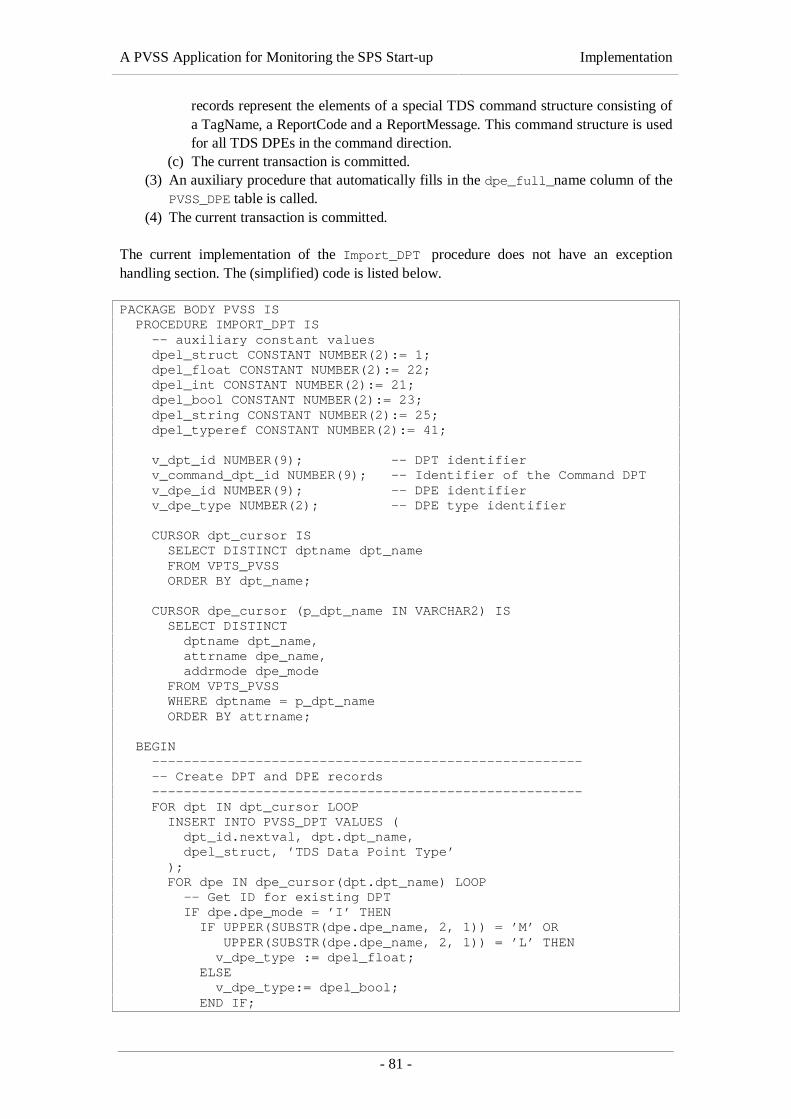
A PVSS Application for Monitoring the SPS Start-up Implementation
- 81 -
records represent the elements of a special TDS command structure consisting ofa TagName, a ReportCode and a ReportMessage. This command structure is usedfor all TDS DPEs in the command direction.
(c) The current transaction is committed.(3) An auxiliary procedure that automatically fills in the dpe_full_name column of the
PVSS_DPE table is called.(4) The current transaction is committed.
The current implementation of the Import_DPT procedure does not have an exceptionhandling section. The (simplified) code is listed below.
PACKAGE BODY PVSS IS PROCEDURE IMPORT_DPT IS -- auxiliary constant values dpel_struct CONSTANT NUMBER(2):= 1; dpel_float CONSTANT NUMBER(2):= 22; dpel_int CONSTANT NUMBER(2):= 21; dpel_bool CONSTANT NUMBER(2):= 23; dpel_string CONSTANT NUMBER(2):= 25; dpel_typeref CONSTANT NUMBER(2):= 41;
v_dpt_id NUMBER(9); -- DPT identifier v_command_dpt_id NUMBER(9); -- Identifier of the Command DPT v_dpe_id NUMBER(9); -- DPE identifier v_dpe_type NUMBER(2); -- DPE type identifier
CURSOR dpt_cursor IS SELECT DISTINCT dptname dpt_name FROM VPTS_PVSS ORDER BY dpt_name;
CURSOR dpe_cursor (p_dpt_name IN VARCHAR2) IS SELECT DISTINCT dptname dpt_name, attrname dpe_name, addrmode dpe_mode FROM VPTS_PVSS WHERE dptname = p_dpt_name ORDER BY attrname;
BEGIN ------------------------------------------------------ -- Create DPT and DPE records ------------------------------------------------------ FOR dpt IN dpt_cursor LOOP INSERT INTO PVSS_DPT VALUES ( dpt_id.nextval, dpt.dpt_name, dpel_struct, ’TDS Data Point Type’ ); FOR dpe IN dpe_cursor(dpt.dpt_name) LOOP -- Get ID for existing DPT IF dpe.dpe_mode = ’I’ THEN IF UPPER(SUBSTR(dpe.dpe_name, 2, 1)) = ’M’ OR UPPER(SUBSTR(dpe.dpe_name, 2, 1)) = ’L’ THEN v_dpe_type := dpel_float; ELSE v_dpe_type:= dpel_bool; END IF;
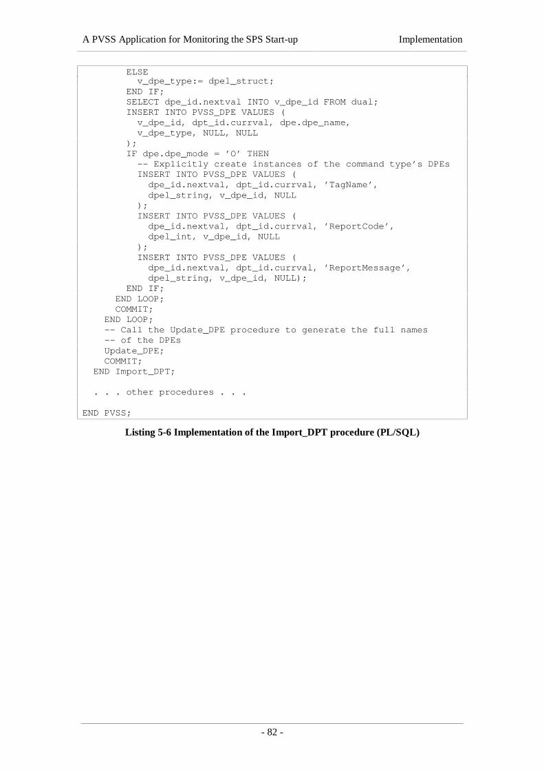
A PVSS Application for Monitoring the SPS Start-up Implementation
- 82 -
ELSE v_dpe_type:= dpel_struct; END IF; SELECT dpe_id.nextval INTO v_dpe_id FROM dual; INSERT INTO PVSS_DPE VALUES ( v_dpe_id, dpt_id.currval, dpe.dpe_name, v_dpe_type, NULL, NULL ); IF dpe.dpe_mode = ’O’ THEN -- Explicitly create instances of the command type’s DPEs INSERT INTO PVSS_DPE VALUES ( dpe_id.nextval, dpt_id.currval, ’TagName’, dpel_string, v_dpe_id, NULL ); INSERT INTO PVSS_DPE VALUES ( dpe_id.nextval, dpt_id.currval, ’ReportCode’, dpel_int, v_dpe_id, NULL ); INSERT INTO PVSS_DPE VALUES ( dpe_id.nextval, dpt_id.currval, ’ReportMessage’, dpel_string, v_dpe_id, NULL); END IF; END LOOP; COMMIT; END LOOP; -- Call the Update_DPE procedure to generate the full names -- of the DPEs Update_DPE; COMMIT; END Import_DPT;
. . . other procedures . . .
END PVSS;
Listing 5-6 Implementation of the Import_DPT procedure (PL/SQL)
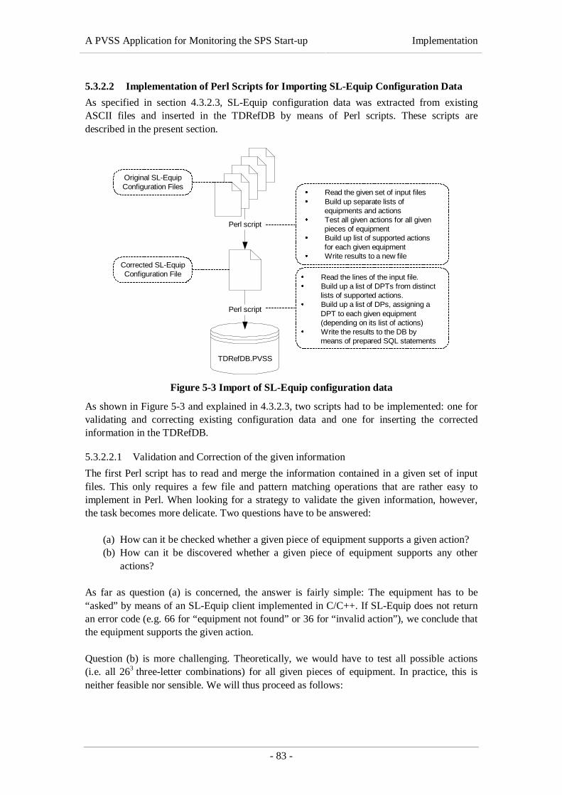
A PVSS Application for Monitoring the SPS Start-up Implementation
- 83 -
5.3.2.2 Implementation of Perl Scripts for Importing SL-Equip Configuration Data
As specified in section 4.3.2.3, SL-Equip configuration data was extracted from existingASCII files and inserted in the TDRefDB by means of Perl scripts. These scripts aredescribed in the present section.
TDRefDB.PVSS
Perl script
Perl script
é Read the given set of input filesé Build up separate lists of
equipments and actionsé Test all given actions for all given
pieces of equipmenté Build up list of supported actions
for each given equipmenté Write results to a new file
é Read the lines of the input file.é Build up a list of DPTs from distinct
lists of supported actions.é Build up a list of DPs, assigning a
DPT to each given equipment(depending on its list of actions)
é Write the results to the DB bymeans of prepared SQL statements
Corrected SL-EquipConfiguration File
Original SL-EquipConfiguration Files
Figure 5-3 Import of SL-Equip configuration data
As shown in Figure 5-3 and explained in 4.3.2.3, two scripts had to be implemented: one forvalidating and correcting existing configuration data and one for inserting the correctedinformation in the TDRefDB.
5.3.2.2.1 Validation and Correction of the given information
The first Perl script has to read and merge the information contained in a given set of inputfiles. This only requires a few file and pattern matching operations that are rather easy toimplement in Perl. When looking for a strategy to validate the given information, however,the task becomes more delicate. Two questions have to be answered:
(a) How can it be checked whether a given piece of equipment supports a given action?(b) How can it be discovered whether a given piece of equipment supports any other
actions?
As far as question (a) is concerned, the answer is fairly simple: The equipment has to be“asked” by means of an SL-Equip client implemented in C/C++. If SL-Equip does not returnan error code (e.g. 66 for “equipment not found” or 36 for “invalid action”), we conclude thatthe equipment supports the given action.
Question (b) is more challenging. Theoretically, we would have to test all possible actions(i.e. all 263 three-letter combinations) for all given pieces of equipment. In practice, this isneither feasible nor sensible. We will thus proceed as follows:
A PVSS Application for Monitoring the SPS Start-up Implementation
- 84 -
(1) Equipment name and action are separated. Consequently, we obtain one listcontaining the identifiers of all pieces of equipment and one list containing all actionsassociated with ANY equipment.
(2) Each of the actions on the action list is tested for all equipment on the equipment list.(3) As a result, a map (i. e. an associative array) of supported actions for each given
piece of equipment is built up and written to the output file.
This procedure does not guarantee that all supported actions for a given piece of equipmentwill be found, for there could be actions that are not mentioned in any of the configurationfiles. Hence, they would never be tested. For this reason, a manual check of the results by thepersons responsible for the equipment would be desirable.
The code of the Perl script for validating the input files is listed in Appendix C.
5.3.2.2.2 Insertion in the TDRefDB
The second Perl script takes the corrected SL-Equip configuration file produced by the scriptdescribed in the previous section as input. It reads the data contained in the file and processesit in a way that PVSS DPTs, DPs and _address configs can be extracted and entered in theTDRefDB.
We illustrate this processing by means of an example. Let us assume that the followingconfiguration file (which is extracted from a real configuration file) is given:
EMD002/A2 ELECA2_EMD002 --- --- --- VSNEBD213/A2 ELECA2_EBD213 STV SAL SAD ---EME200/A2 ELECA2_EME200 --- --- --- VSNEMD212/A2 ELECA2_EMD212 STV SAL SAD ---EBE215/A2 ELECA2_EBE215 --- --- --- VSNEMD213/A2 ELECA2_EMD213 STV SAL SAD ---
Listing 5-7 Example of a corrected SL-Equip configuration file
First of all, the script has to define DPTs for groups of equipment supporting the same list ofactions. The DPTs are automatically named ELEC1 to ELECn since the information containedin SL-Equip configuration files mainly concerns electrical equipment.
For the example above, two different DPTs would be defined:
• ELEC1: supporting one single action called VSN and• ELEC2: supporting the actions SAD, SAL and STV (in alphabetical order).
In a second step, DPs corresponding to equipment names are defined and assigned a suitableDPT. For the example above, six DPs would be defined:
• ELECA2_EMD002 of type ELEC1
• ELECA2_EME200 of type ELEC1
• ELECA2_EBE215 of type ELEC1
• ELECA2_EBD213 of type ELEC2
• ELECA2_EMD212 of type ELEC2
• ELECA2_EMD213 of type ELEC2

A PVSS Application for Monitoring the SPS Start-up Implementation
- 85 -
Finally, _address configs have to be generated from the given information. All fields of the_address config are filled with real or default values, following the rules for PVSS addressmapping defined in chapter 4.2.2.
As soon as all the required information is defined, it is written to the database by means of thePerl Database Interface (DBI) package. This object-oriented package allows the creation ofprepared SQL statements and their consecutive execution. The code of this second Perl scriptis equally listed in Appendix C.
5.3.3 Implementation of an SQL Script for Exporting PVSS Configuration Data
This section deals with the SQL script for extracting PVSS configuration information fromthe TDRefDB. The requirements for the script have been specified in chapter 4.3.3.
The script is divided in two parts:
(1) A series of commands configures the SQL*PLUS environment and the script’s outputformat.
(2) A succession of SQL statements extracts PVSS configuration information from thedatabase and writes it to an output file.
The commands in the first part of the script mainly assign values to SQL*PLUS environmentvariables (see [Oracle, 1997]) with the intention of formatting the script’s output in a way thatit can directly be spooled to a text file. For this purpose, all SQL*PLUS options that couldunintentionally re-format the queries’ output (e. g. command echoing, column headings, linewrapping, automatic page breaks etc.) are turned off. Furthermore, the output of the script isredirected to a text file instead of being displayed on the screen (SPOOL command).
The SELECT statements in the second part of the script extract information from theTDRefDB user views. The data is formatted in a way that the results are printed in an ASCIIManager-compatible format (see section 4.3.3.1):
ASCII Manager files are divided in sections, where each new section must start with a headerline “declaring” the PVSS attributes represented by the columns of the following section. AsSQL*PLUS does not support simple “print” commands, the sections’ headers had to beselected from Oracle’s DUAL table (e.g. “SELECT ‘test’ FROM DUAL;” would simplyprint “test” to the output file). The sections’ bodies are created by means of SQL queriesaccessing the user views described in chapter 4.3.1.3. These statements select the informationrequired from the database and concatenate the columns retrieved in a way that the output canbe read by the PVSS ASCII Manager. (e.g. “SELECT DPT_NAME ||‘ ‘|| DPT_TYPE FROMVPVSS_DPT;” would print ‘TypeA 1’ to the output file).
The complete code of the SQL script is listed in Appendix D. In order to execute the script, aconnection to the Oracle database account containing the PVSS user views must beestablished. The script can then be executed by entering “START filename.sql” on theSQL*PLUS command line.
5.4 Implementation of the User Interface
To complete the implementation of the SPS Restart Application – from the data acquisitionlevel up to the user interface level – this section explains how the application’s user interface

A PVSS Application for Monitoring the SPS Start-up Implementation
- 86 -
has been created. As mentioned in section 4.4, only one PVSS panel has been developed bythe author, further panels will later be developed by TCR operators.
The sample panel created in the course of this thesis work is based on the functional diagramof SPS sextant 2 (BA2), which is displayed in Figure 4-13 of the previous chapter. BA2contains a number of subsystems involved in the machine’s start-up:
• 18 Kilovolt electricity,• 400 Volt electricity,• Vacuum,• Demineralised water for cooling,• Raw water (a primary water circuit feeding the demineralised water circuits• etc.
Each of these subsystems had to be analysed in order to find out how the current state of thesystem (see Table 4-10) can be determined. For this purpose, existing applications displayingSPS equipment information have been analysed. Figure 5-4 displays a mimic diagram of suchan application that is currently used in the TCR. The figure represents electrical installationsin BA2: (1) the “18 Kilovolt stable” subsystem in the upper part of the diagram and (2) the400 Volt stable subsystem in the lower part.
5,0 A 3,4 A
19,3 kV
-1,0 V
-1,0 MV
1,8 A
EBD2/A2
EMD2/A2EMD
213EMD
212
EMD211
EMT211
EBD213-06
2MVA
Voltmeter(SL-Equip: ELECA2_EME200)
Circuit breaker(SL-Equip: ELECA2_EBD213)
Circuit breaker(SL-Equip: ELECA2_EMD211)
Transformer(no data available)
400 V bus bar(no data available)
18 kV bus bar(no data available)
Voltmeter(no data available)
Figure 5-4 Screenshot of UMMI application
The diagram provides all the information we need to animate the corresponding boxes in ourPVSS panel. We see that the “18 kV stable” subsystem is “ST_OK” if there is a voltage on the“18 kV bus bar” (purple line in the above diagram). This voltage is measured by a voltmeterlabelled “EMD2/A2” and can be read out via SL-Equip. If there is no voltage (or a voltagemuch lower or higher than 18 kV), the “18 kV stable” subsystem shall be in “ST_FAULT”state.

A PVSS Application for Monitoring the SPS Start-up Implementation
- 87 -
A third state, “ST_INVALID”, had to be introduced in order to indicate that the value of apiece of equipment could not be determined at run-time, due to a hardware, transmission ordriver error.
The “400 Volt stable” subsystem is slightly more complicated as it depends on the voltage onthe 18 kV bus bar. As the voltage on the 400 V bus bar cannot be read out directly (thevoltmeter concerned is not connected to SL-Equip), three parameters have to be taken intoaccount when determining the state of the 400 V bus bar:
(1) the voltage on the 18 kV bus bar must be OK (~ 18 kV),(2) the circuit breaker “EMD 211” must be closed and(3) the circuit breaker “EBD 213-06” must be closed.
All the information required for the “18 kV stable” and “400 V stable” subsystems isavailable via SL-Equip and can therefore be accessed from PVSS by means of the SL-Equipdriver developed in the course of this thesis work. Information about the “vacuum” and “18kV pulsed” subsystems is equally acquired via SL-Equip while “raw water” and“demineralised water” information is acquired via the TDS driver.
All other subsystems depicted in the Figure 4-13 are supervised and controlled by systemsthat are currently not accessible from PVSS. Consequently, the corresponding boxes in thePVSS panel could not be animated (ST_NOT_ANIMATED). For each of the subsystemsmentioned above, a box in the PVSS mimic diagram had to be created. The resulting panel isshown in Figure 5-5. As it was mentioned in the design chapter, the panel looks very similarto the functional diagram of the BA, depicted in Figure 4-13.
Figure 5-5 Screenshot of the PVSS panel for SPS BA2

A PVSS Application for Monitoring the SPS Start-up Implementation
- 88 -
The background colour of the boxes represents the current state of the subsystem concerned,following the colour conventions described in Table 4-10. How the background colour ischanged at run-time whenever the state of one of the supervised systems changes, is explainedin the following paragraph, taking the “400 V stable” box as an example.
The run-time behaviour of PVSS panels is implemented by means of CONTROL scripts thatare executed whenever certain events (e.g. initialisation, mouse click etc.) occur. In order tochange the background colour of our “400 V stable” box dynamically, depending on thevalues of the DPEs concerned, an “initialisation handler” had to be implemented. Thisfunction is executed as soon as the panel is initialised and connects to the DPEs concerned byregistering a call-back function.
The call-back function is called by PVSS as soon as the value of one of the registered DPEschanges. It evaluates the new values and sets the background colour of the box accordingly.The code of the initialisation handler and the call-back function is listed in Listing 5-8.
main() { dpConnect("EP_setBackColorCB", //ELECA2_EBD213 "st_tsi:ELECA2_EBD213.STV:_online.._value", "st_tsi:ELECA2_EBD213.STV:_online.._aut_inv", //ELECA2_EBMD211 "st_tsi:ELECA2_EMD211.STV:_online.._value", "st_tsi:ELECA2_EMD211.STV:_online.._aut_inv", //ELECA2_EME200 "st_tsi:ELECA2_EME200.VSN:_online.._value", "st_tsi:ELECA2_EME200.VSN:_online.._aut_inv" );}
EP_setBackColorCB( string ebd213valStr, float ebd213, string ebd213invStr, float ebd213_invalid, string emd211valStr, float emd211, string emd211invStr, float emd211_invalid, string eme200valStr, float eme200, string eme200invStr, float eme200_invalid) { if (ebd213_invalid || emd211_invalid || eme200_invalid) { this.backCol = "ST_INVALID"; } else if (eme200 > 0 && ebd213 == 2 && emd211 == 2) { this.backCol = "ST_OK"; } else if (ebd213 == 1 || emd211 == 1) { this.backCol = "ST_FAULT"; } else { this.backCol = "ST_INVALID"; }}
Listing 5-8 PVSS Control Script embedded in a user interface panel
All other boxes have been animated in a similar way, using different DPEs.
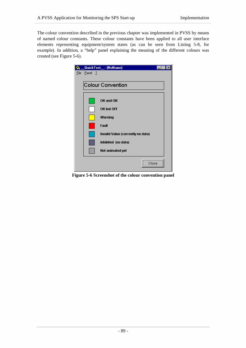
A PVSS Application for Monitoring the SPS Start-up Implementation
- 89 -
The colour convention described in the previous chapter was implemented in PVSS by meansof named colour constants. These colour constants have been applied to all user interfaceelements representing equipment/system states (as can be seen from Listing 5-8, forexample). In addition, a “help” panel explaining the meaning of the different colours wascreated (see Figure 5-6).
Figure 5-6 Screenshot of the colour convention panel

A PVSS Application for Monitoring the SPS Start-up Validation and Verification
- 90 -
6. VALIDATION AND VERIFICATIONThis chapter outlines the measures that were taken to test the different components of the SPSRestart Application as well as the system as a whole. Following [Sommerville, 1995], testinginvolves two different aspects:
(1) “Do we build the right product?” (validation)It has to be ensured that the produced software system meets the needs of thecustomer.
(2) “Do we build the product right?” (verification)It has to be checked whether the system conforms to its specification and producesthe expected results.
[ESA BSSC, 1994] defines validation as the evaluation of software at the end of the softwaredevelopment process to ensure compliance with the user requirements. This definition seesvalidation as end-to-end verification, which means that checks whether the “right product”has been built are only done once the product has been finished. In the case of the SPS RestartApplication, validation steps have been included in the software engineering process. In orderto make sure that the proposed solution meets the users’ requirements, the application hasbeen developed in close co-operation with TCR operators. Informal reviews and earlypresentations of prototypes proved to be very constructive. Furthermore, the participation offuture users in the development process assured that the users identified with the product andwere thus satisfied with the final solution.
According to [ESA BSSC, 1994], the verification aspect of testing is supposed to show that(a) the product performs as specified and (b) the product does not contain defects that preventit from performing as specified. Due to a lack of development time, verification has not beendone in a very structured way. A series of white-box tests has been performed at the end ofthe implementation phase but there was not enough time to elaborate a structured test planand to test the system in an exhaustive manner.
6.1 Component Tests
This section explains how each of the SPS Restart Application’s components presented in thisthesis work has been tested, starting with the PVSS system’s set-up.
6.1.1 PVSS System Set-up
Two kinds of tests regarding the system’s set-up (see section 5.1) were performed:
(1) Redundancy tests evaluating the general stability and robustness of the system.(2) Distribution tests checking whether data exchange with external PVSS systems is
possible.
As high dependability was one of the system’s central design goals (see section 3.2.1.1), ithad to be verified whether the system continues to work in case of a partial or completebreakdown of one of the two redundant servers. This redundancy test procedure wasfacilitated by the fact that PVSS provides a standard redundancy overview panel fordisplaying the current state of all the components making up a redundant PVSS system. Thisstandard panel was slightly modified in order to reflect the particular configuration of the SPS

A PVSS Application for Monitoring the SPS Start-up Validation and Verification
- 91 -
Restart Application (see Figure 6-1). The modified redundancy overview panel and the PVSSPARA module were then started on a Microsoft Windows NT 4.0 machine for test execution.
Figure 6-1 PVSS Redundancy overview panel (both servers up and running)
The following (non-exhaustive) list gives some examples of redundancy tests that have beenperformed:
• One of the redundant PVSS servers was switched off unexpectedly in order tosimulate the breakdown of one of the two redundancy partners. The objective of thistest case was to check whether the remaining server becomes active (as specified in[ETM, 2000]) and ensures the uninterrupted availability of the system. The test wassuccessful; no data was lost.
• The primary network connection between the two PVSS servers was removed at run-time in order to check whether the system remains stable although no data can beexchanged (as the secondary network connection is used for the exchange of statusinformation only). As expected, the system continued to work without interruptionand no data was lost. When the network connection was re-established, the inactivePVSS system was restarted automatically in order to synchronise its database withthe active one.
• The secondary network connection, i. e. the direct link between the two servers, wasremoved at run-time. In this case, status information was exchanged via the primarynetwork connection and the system continued to operate normally.
• Selected tasks (managers) of the active system were killed in order to check if theother system (i. e. the system in a better condition) becomes active and ensures thesystem’s operation. The test case was successful; the killed manager (in the case ofthe Event and Data Managers: the complete system) was restarted automatically andno data was lost.

A PVSS Application for Monitoring the SPS Start-up Validation and Verification
- 92 -
As mentioned above, the correct functioning of the distribution mechanism had to be checkedas well. For this purpose, a second (non-redundant) PVSS system was set up and configuredfor data exchange with the redundant system for the SPS Restart Application. Subsequently, asynoptic panel accessing data points (DPs) from both systems was created. The set-up for thedistribution tests is shown in Figure 6-2. The test panel was executed on both systems in orderto verify if the systems can mutually access their data points. All data was displayedcorrectly; we can thus conclude that the distribution mechanism works.
lnxdevtim1.cern.chRedhat Linux 6.1
st_tsi_dev
lnxoptim2.cern.chRedhat Linux 6.1
st_tsi
lnxoptim1.cern.chRedhat Linux 6.1
st_tsi
SLE
Dist
Data Event
Ctrl
TDS
Event Data
Ctrl
TDSSLE
Dist
Redu Reduredundant Event Data
CtrlDist
User Interface Project
SPS Restart Application Test System
Figure 6-2 PVSS Set-up for distribution tests
6.1.2 SL-Equip Driver
The SL-Equip driver was thoroughly tested towards the end of the implementation phase. Itscorrect functioning is crucial for the entire SPS Restart Application. First of all, it had to beensured that the driver conforms to its specification and provides all the required functionality(see 3.2.2 and 4.2), and then it had to be checked whether all data acquired and sent by thedriver is correct.
It goes without saying that read and write actions could not immediately be tried out onoperational equipment, for the risk of accidental damage would have been intolerable. For thisreason, a piece of non-functional equipment supporting all SL-Equip modes without causingany hardware action was used for a first series of tests. Only when these tests had beencompleted successfully, the driver was tested on operational SPS equipment.
On the PVSS side, the tests were prepared by creating a new DPT with elements of all typessupported by the SL-Equip driver (see Table 4-3). A DP of this type was instantiated and_address configs were attached to all the DPEs in order to connect them to the test equipment.Subsequently, read and write actions were performed in order to test data acquisition andsending commands for all supported data types. The following (non-exhaustive) list givesexamples of test cases that were executed:

A PVSS Application for Monitoring the SPS Start-up Validation and Verification
- 93 -
• New _address configs were attached to DPEs via the PVSS PARA module and andvia the PVSS ASCII Manager. They were configured in a way that the DPEs wereconnected to the SL-Equip driver in order to verify whether new address informationis (a) transmitted to the driver and (b) correctly processed.
• Different parameters of existing _address configs (e.g. SL-Equip address, pollinginterval etc.) were modified in order to check whether the driver is capable ofreacting to these modifications.
• Existing _address configs were removed via the PVSS PARA module in order tocheck whether the address information is equally removed from the driver’s internallists. This was to ensure that the driver does not continue to acquire data that is notused/required by PVSS.
• Data was written to SL-Equip in order to check if the information is sent in thecorrect format.
• Data was read from SL-Equip in order to check if the information is read out andconverted in the correct format.
• etc.
Some dysfunctional tests were also performed in order to check the driver’s error handling(e.g. if invalid addresses are rejected). The debug mechanism described in the previouschapter proved to be very useful during testing, especially for checking whether the driver’sinternal lists of data points are managed correctly (adding/removing _address configs).Furthermore, several implementation mistakes in the transformation classes (see 5.2.2.6)could be detected, located and corrected in an efficient way.
As the SL-Equip driver has to run in a technical service context and must be available 24hours per day, 365 days per year without interruption, the detection of memory leaks was amain concern during testing/debugging. For this reason, ParaSoft’s Insure++ suite, acomprehensive tool suite for error detection in C/C++ programs, was used to spot bugs andinefficiencies in memory handling.
Performance and load tests could not be performed due to a lack of development time.
6.1.3 Static Configuration Database and Data Loaders
This section covers the test procedure for the static configuration database described in 4.3, itsdata import scripts and procedures (4.3.2) and the SQL loader script for data extraction(4.3.3). Basically, the configuration database works “off-line” and has no run-time connectionto the PVSS system. A connection to PVSS is only established when the text file produced bythe export script is injected to PVSS by means of the ASCII Manager. The approach that waschosen for testing the off-line database was thus different from the test methods described inthe previous sections. The whole functionality of the database system (import, storage andexport of configuration data) was tested in one big test case, consisting of five steps presentedin below. Before the test could be executed, however, a number of preconditions had to beestablished:
• The TDRefDB table structure described in 4.3.1.2 as well as the user views describedin 4.3.1.3 have been created.
A PVSS Application for Monitoring the SPS Start-up Validation and Verification
- 94 -
• The reference tables (PVSS_ADDRESS_TYPE, PVSS_ADDRESS_DATATYPE,
PVSS_ADDRESS_MODE, PVSS_DISTRIB_TYPE, PVSS_DRIVER and PVSS_DPE_TYPE)have been filled with data correctly.
• The remaining tables (PVSS_DPT, PVSS_DPE, PVSS_DP, PVSS_DPE_TYPEREF,PVSS_ADDRESS and PVSS_DPE_COMMENT) contain no data.
• The VPTS_PVSS view exists and selects existing TDS configuration data from theTDRefDB (see 4.3.2.2).
• The data contained in the VPTS_PVSS view is consistent (no duplicate identifiers, nounexpected NULL values etc.).
• A set of correctly formatted SL-Equip configuration files (see 4.3.2.3.1) is available.• The PVSS system for the SPS Restart Application is correctly set up and running
(required for test step (5) only).
As soon as these preconditions had been established, the five test steps listed below wereexecuted. Each test step is followed by a postcondition that represents the immediate result ofthe action performed:
(1) Execute the stored procedures for importing TDS configuration information.Postcondition: The PVSS_DPT, PVSS_DPE, PVSS_DP, PVSS_ADDRESS andPVSS_DPE_COMMENT tables have been filled with data from the VPTS_PVSS view.
(2) Execute the Perl script for validating and correcting the existing configuration files.Postcondition: A correctly formatted SL-Equip configuration file containingvalidated and corrected configuration data has been generated.
(3) Execute the Perl script for importing SL-Equip configuration information.Postcondition: The data contained in the corrected SL-Equip configuration file hasbeen imported in the PVSS_DPT, PVSS_DPE, PVSS_DP and PVSS_ADDRESS tables.
(4) Execute the SQL script for extracting data from the TDRefDB.Postcondition: An ASCII Manager-compatible text file containing all PVSSconfiguration information stored in the TDRefDB tables (see 4.3.1.2) has beengenerated.
(5) Import the generated text file into the PVSS system by means of the ASCII Manager.Postcondition: The DPTs, DPs, _address configs, _distrib configs and commentsspecified in the input file have been created in the PVSS system.
In order to verify whether the test was successful, the postconditions listed above had to bechecked. Naturally, the correctness of the imported and exported data could not be verifiedfor all data only but by means of some randomly chosen examples. As all the postconditionswere met for the sample data, the test of the configuration database system was considered assuccessful.
6.1.4 User Interface Panels
The application’s user interface described in chapters 4.4 and 5.4 could not be tested “stand-alone”, for it requires at least a running PVSS system with TDS and SL-Equip data pointsdefined. Ideally, the SL-Equip and TDS drivers should also be running in order to verify if themachine state displayed by the SPS Restart Application is identical with the machine statedisplayed by existing TCR applications used for comparison.
When the panel was tested on the PVSS system for the SPS Restart Application (see chapter4.1), it displayed exactly the same machine states as the TCR applications (see Figure 5-4, for

A PVSS Application for Monitoring the SPS Start-up Validation and Verification
- 95 -
example). This proves that the whole data acquisition chain –from the driver up to the userinterface panel – works. All the same, the panel’s functionality also needed to be tested forother machine states (e.g. when one of the subsystem fails, when information about a certainsubsystem is temporarily unavailable etc.). It goes without saying that it was out of questionto cause a malfunction of the particle accelerator just for testing a new PVSS panel. For thisreason, failures had to be simulated by changing values internally in PVSS. An example ofsuch a simulation is given below.
Figure 6-3 shows a screenshot of the PVSS PARA module that is used to edit DPTs and DPsat run-time. The current values of read-only DPEs can be changed without affecting the “realvalue” in the connected hardware element. The value is only sent to the hardware if the DPEconcerned is configured for sending commands (write direction). For instance, we couldchange the value of the DP representing the voltage on the 18kV bus bar (see chapter 4.4,Figure 4-13) to 100.000 Volt.
Figure 6-3 Screenshot of the PVSS PARA module during test execution
The application’s user interface should react to this value change and change the colour of thebox representing the 18 kV subsystem of BA2 to red (ST_FAULT). Figure 6-4 shows the resultof the test.
Many other tests like the example above were tried out and all of them delivered the expectedresults.

A PVSS Application for Monitoring the SPS Start-up Validation and Verification
- 96 -
Figure 6-4 Screenshot of the BA2 mimic diagram during test execution
6.2 System Tests
As the tests of the user interface panel described in the previous section required a fullyconfigured PVSS system including SL-Equip and TDS drivers, they can be regarded as a firstseries of system tests. A complete system test including functional tests, performance tests,stress tests and load tests will be performed as soon as the entire SPS Restart Application,including the panels to be implemented by TCR operators, is finished. A test plan documentdefining the test suite to be used for the acceptance tests is being prepared.
A PVSS Application for Monitoring the SPS Start-up Conclusion
- 97 -
7. CONCLUSIONThis last chapter summarises the main points of this thesis. The goal of the work is reiteratedand a summary of the proposed solution is presented. Furthermore, some future extensionsand potential improvements are suggested.
7.1 Goal and Solution
The aim of this thesis was the development of a SCADA application (see chapter 2.1) formonitoring the start-up of the Super Proton Synchrotron, CERN’s second largest particleaccelerator, after major breakdowns. The application had to be based on PVSS II, the CERNrecommended SCADA product, developed by the Austrian company ETM (see chapter 2.2).
The problem posed in chapter 3 was broken down to four interdependent subtasks:
(1) A redundant and distributed PVSS II system had to be set up on two UNIX servers asa basis for the application.
(2) A PVSS Driver Manager for doing data exchange between PVSS and CERN’s SL-Equip middleware (see chapter 2.3) had to be designed and implemented.
(3) An off-line database system for managing static PVSS configuration data andimporting it to PVSS II had to be developed.
(4) Several mimic diagrams, so-called PVSS panels, for the application’s user interfacehad to be created.
(1), (2) and (4) are closely related and correspond to the layers of the SCADA system’s three-tier architecture (see Figure 2-2): the driver corresponds to the data layer, the PVSS II coresystem to the co-ordination and storage layer and the mimic diagrams to the user interface(presentation) layer.
The set-up and configuration of the PVSS II system was a challenge. For one thing, highdependability was a central design requirement, as the SPS Restart Application has to run intwo of CERN’s main control rooms and is therefore supposed to be available 24 hours a day,365 days a year. The possibility of doing data exchange with other PVSS systems at CERNwas also demanded. Furthermore, the system had to be installed on different operatingsystems: Redhat Linux 6.1 and Microsoft Windows NT 4.0/Windows 2000. Theserequirements and constraints have led to a redundant, distributed and scattered PVSS systemthat had to be well tested before it could become operational. The first series of system testswas successful, as described in chapter 6.
The SL-Equip Driver Manager has been developed following the Unified ModellingLanguage (UML) methodology. After a thorough analysis of the problem, object-orientedclass and object designs have been established. The driver has been implemented in C++ on aRedhat Linux 6.1 platform, using the PVSS and SL-Equip APIs. Contrary to other PVSSdrivers, the SL-Equip driver is only available for Linux platforms, for the SL-Equip API hasnot been ported to Microsoft Windows platforms yet. The driver has been debugged andtested intensively in order to guarantee high stability and availability.
The design for the static configuration database described in chapter 4.3 has been establishedin accordance with the ST/MO group’s database design rules. A server model for the databasehas been designed using the Oracle Designer 6 tool suite and then automatically exported to

A PVSS Application for Monitoring the SPS Start-up Conclusion
- 98 -
an Oracle 8 database. In addition to the database structure for storing PVSS data point types,data points and configs (see 2.2.2), a set of PL/SQL procedures and Perl scripts for importingexisting configuration data from various sources has been designed and implemented.Furthermore, an SQL script for extracting configuration data from the database and exportingit to ASCII text files that can be injected to PVSS by means of the PVSS ASCII Manager hasbeen developed.
A prototype for the SPS Restart Application’s user interface has been implemented as a seriesof PVSS panels. The panel layout is based on functional diagrams of the Super ProtonSynchrotron, developed in the course of the Gestion Technique de Pannes Majeures project(see 1.2). The panel has been animated with live data acquired by the SL-Equip and TDSDriver Managers and reflects the current state of one of the SPS sextants (BA2).
7.2 Unsolved Problems
This section covers open issues – parts of the problem that have not been solved in the courseof this thesis work.
Although the implementation of the full series of user interface panels was not included in thescope of this thesis, it has to be mentioned that the user interface still needs to be completedbefore the SPS Restart Application can become operational. At least 8-10 further panelssimilar to the one described in chapter 5.4 need to be created in co-operation with TCRoperators. Of course, the panel developed in the course of this thesis work will serve as anexample for future developments.
7.3 Possible Extensions
This section deals with possible extensions to the components of the SPS Restart Application.In my opinion, the SL-Equip driver and the PVSS configuration database could both beimproved.
Regarding the SL-Equip Driver Manager, it is thinkable to extend its functionality to all datatypes (modes) supported by SL-Equip. Currently, only the data types listed in Table 4-3 aresupported. Such an extension is not at all necessary for the SPS Restart Application.However, it would increase the usability of the driver for other projects.
Regarding the static PVSS configuration database, the current data loading strategy is a veryrudimentary solution. First of all, there is no way to edit the configuration informationcontained in the TDRefDB in a reasonable way. As a consequence, a tool for modifyingPVSS configuration data directly in the database, e. g. via a Web interface or an Oracle Formsapplication, would be very useful. Second, the data loading procedure is not very efficient, forall information contained in the configuration database is first exported to an ASCII file thatis then injected to PVSS via the ASCII Manager. Even if only one database record (e.g. oneDP) changes, the whole file has to be reloaded – a procedure that took more than one hourduring tests. For this reason, it would be very useful to have a more flexible database loadingtool, e. g. an additional PVSS API Manager that connects to PVSS and the TDRefDBrespectively and synchronises the two databases. Naturally, the development of such an APIManager requires a lot of development effort and has to be done in a separate project.

A PVSS Application for Monitoring the SPS Start-up Conclusion
- 99 -
7.4 Concluding Remarks
Summing up, we can say that the project was very interesting and highly challenging from anorganizational as well as from a technical point of view. Co-operation of several organic unitsat CERN, notably the Technical Control Room, the SL/CO group and the ST/MO/IN sectionwas crucial for the project’s success, for expert knowledge in many different domains wasrequired (e.g. knowledge about the systems involved in the SPS restart, knowledge about theSL-Equip architecture etc.). A lot of different technologies, e.g. SCADA systems, object-oriented design and implementation, UNIX and Microsoft Windows operating systems,database management systems etc., had to be mastered to successfully develop all thesystem’s components. However, a global vision of the system was equally important, tointegrate the application’s components in a way that a highly dependable and reliable PVSSapplication, ready to be deployed to the CERN control rooms, was reached.
A PVSS Application for Monitoring the SPS Start-up Table of Figures
- 100 -
8. TABLE OF FIGURESFigure 1-1 How the ST/MO group is embedded in the CERN hierarchy .............................................10
Figure 2-1 Example of a generic SCADA system (architecture) .........................................................15
Figure 2-2 General PVSS system architecture ...................................................................................21
Figure 2-3 Example of a scattered PVSS system ................................................................................23
Figure 2-4 Example of a distributed PVSS system..............................................................................24
Figure 2-5 Architecture of a redundant PVSS system.........................................................................25
Figure 2-6 SL-Equip system architecture ..........................................................................................26
Figure 2-7 The CERN accelerator complex ......................................................................................29
Figure 4-1 Global view of the SPS Restart Application......................................................................33
Figure 4-2 Architecture of the proposed system.................................................................................35
Figure 4-3 Functionality of the PVSS driver layer .............................................................................37
Figure 4-4 Class diagram of the SL-Equip driver’s core classes ........................................................42
Figure 4-5 Class diagram of the SL-Equip Driver Manager (II).........................................................44
Figure 4-6 Class diagram of the SL-Equip Driver Manager (III) .......................................................45
Figure 4-7 Object model of the SL-Equip driver during its initialisation ............................................47
Figure 4-8 Server model of the TDRefDB table structure for PVSS configuration data.......................52
Figure 4-9 Server model of TDRefDB user views...............................................................................57
Figure 4-10 Overview of the data loading strategy ............................................................................59
Figure 4-11 Server model of the VPTS_PVSS view ............................................................................59
Figure 4-12 Schematic representation of the SPS complex.................................................................65
Figure 4-13 Functional diagram for SPS BA2 ...................................................................................66
Figure 5-1 Overview of the PVSS system’s implementation................................................................68
Figure 5-2 Screenshot of the parameterisation panel for the SL-Equip driver ....................................77
Figure 5-3 Import of SL-Equip configuration data.............................................................................83
Figure 5-4 Screenshot of UMMI application .....................................................................................86
Figure 5-5 Screenshot of the PVSS panel for SPS BA2.......................................................................87
Figure 5-6 Screenshot of the colour convention panel .......................................................................89
Figure 6-1 PVSS Redundancy overview panel (both servers up and running).....................................91
Figure 6-2 PVSS Set-up for distribution tests.....................................................................................92
Figure 6-3 Screenshot of the PVSS PARA module during test execution.............................................95
Figure 6-4 Screenshot of the BA2 mimic diagram during test execution .............................................96

A PVSS Application for Monitoring the SPS Start-up Table of Listings
- 101 -
9. TABLE OF LISTINGSListing 4-1 Example of a complex DPT definition in ASCII Manager format ......................................54
Listing 4-2 EBNF representation of the SL-Equip configuration file format .......................................62
Listing 4-3 EBNF representation of the ASCII Manager file format ...................................................64
Listing 5-1 Implementation of the signalHandler method (SleDriver class) ........................................71
Listing 5-2 Implementation of the switchDbgLevel method (SleResources class). ...............................72
Listing 5-3 Implementation of the addDpPa method (SleMapper class)..............................................74
Listing 5-4 Implementation of the toPeriph method (SleTransFloat class) ..........................................76
Listing 5-5 Statements for creating the VPVSS_DPT and VPVSS_DPE views (SQL) ..........................78
Listing 5-6 Implementation of the Import_DPT procedure (PL/SQL)..................................................82
Listing 5-7 Example of a corrected SL-Equip configuration file .........................................................84
Listing 5-8 PVSS Control Script embedded in a user interface panel..................................................88
A PVSS Application for Monitoring the SPS Start-up List of Tables
- 102 -
10. LIST OF TABLESTable 2-1 Definition of SL-Equip modes............................................................................................28
Table 4-1 Structure of the _address config ........................................................................................38
Table 4-2 Structure of the _distrib config ..........................................................................................38
Table 4-3 Mapping of PVSS data types..............................................................................................40
Table 4-4 Example of a complex DPT definition (PVSS_DPT table) ..................................................54
Table 4-5 Example of a complex DPT definition (PVSS_DPE table) ..................................................54
Table 4-6 Example of a DP definition (PVSS_DP table) ....................................................................55
Table 4-7 Example of address configurations (PVSS_ADDRESS table)..............................................55
Table 4-8 Example of DPE comments (PVSS_DPE_COMMENT table) .............................................56
Table 4-9 Mapping between the VPTS_PVSS view and the described database structure ...................60
Table 4-10 Definition of system states and colour codes ....................................................................67
Table 5-1 Example of a DPT definition in VPVSS_DPE.....................................................................79

A PVSS Application for Monitoring the SPS Start-up References
- 103 -
11. REFERENCES
11.1 Literature
[Barbacci et al., 1995] Barbacci, Mario; Klein, Mark H.; Longstaff, Thomas H. & Weinstock, Charles B.Quality Attributes (CMU/SEI-95-TR-021). Pittsburgh, Pennsylvania: SoftwareEngineering Institute, Carnegie Mellon University, 1995.
[Boyer, 1999]Boyer, Stuart A. Supervisory Control and Data Acquisition. 2nd ed. USA: IliadEngineering Inc. 1998
[Feuerstein, 1996]Feuerstein, Steven. Advanced Oracle PL/SQL: Programming with Packages. 1st ed.Sebastopol, California: O’Reilly & Associates. 1996
[Gamma et al., 1994]Gamma, Erich; Helm, Richard; Johnson, Ralph and John Vlissides. Design Patterns:Elements of Reusable Object-Oriented Software. Reading Massachusetts: Addison-Wesley, 1994
[Jepson et al., 2000]Jepson, Brian; Oeckhan, Joan and Ram Sadasiv. Database Application Programmingwith Linux. John Wiley and Sons Inc., 2000
[Koch and Loney, 1997]Koch, George and Kevin Loney. Oracle8: The Complete Reference. Berkley,California: Osborne/McGraw-Hill, 1997
[Mayr, 1998]Maryr, Herwig. Software Project Engineering. 4th ed. Hagenberg, Austria:Fachhochschul-Studiengang Software Engineering, 1998
[Pfleeger, 1998]Pfleeger, Shari L. Software Engineering: Theory & Practice. 1st ed. Upper SaddleRiver, New Jersey: Prentice Hall, 1998
[Sommerville, 1995]Sommerville, Ian. Software Engineering. 5th ed. Harlow, England, United Kingdom:Addison Wesley Longman Ltd., 1995
11.2 Papers and Internal Reports
[CERN, 1954]Conseil Européen pour la Recherche Nucléaire (CERN). The CERN Convention.Geneva, Switzerland: CERN, 1954.

A PVSS Application for Monitoring the SPS Start-up References
- 104 -
[Charrue, 1993]Charrue, Pierre et. al. Accessing Equipment in the SPS-LEP ControlsInfrastructure. Geneva, Switzerland: CERN, 1993
[Daneels and Salter, 2000]Daneels, Axel and Wayne Salter. What is SCADA? Geneva, Switzerland: CERNIT/CO, March 2000 <http://ref.cern.ch/CERN/CNL/2000/003/scada/>
[ESA BSSC, 1994]European Space Agency, Board for Software Standardisation and Control. Guide toSoftware Verification and Validation. 1st ed. Noordwijk, The Netherlands: ESAPublications Division, 1994
[Johnson and Foote, 1998]Johnson, Ralph and Brian Foote. Designing Reusable Classes. Journal of Object-Oriented Programming. ½ (1998) pp. 22-35
[Scowen, 1998]Scowen, Roger S. Extended BNF – A generic base standard. Hampton, Middlesex,Great Britain, 1996, <[email protected]>
11.3 Online Help
[ETM, 2000]ETM. PVSS Online Help. Eisenstadt, Austria: ETM, 2001
11.4 World Wide Web References
[NFESC, 1991]Naval Facilities Engineering Service Centre. Introduction to SCADA. published in1991, last visited in 2001-07, <http://energy.nfesc.navy.mil/docs/neesa/scada1.htm>
[Oracle, 1997]Oracle Corporation. Oracle Developer Library, published in December 1997, lastvisited in August 2001, <http://oradoc.cern.ch/73_80doc/content/index-nj.htm>
[Toomey, 1995]Toomey, Warren. Unix Signals. published in 1995, last visited on 2001-08-12,<http://www.cs.adfa.oz.au/teaching/studinfo/csa2/OSLabNotes/node7.html>
[WWW-CERN]CERN. European Organization for Nuclear Research. last visited on 2001-08-31,<http://www.cern.ch>
[WWW-CERNLNX]Fournier, Jerome. CERN Linux Installation. Last modified on 2001-05-18, lastvisited on 2001-08-17, <http://wwwinfo.cern.ch/dis/linux/install/index.html>
A PVSS Application for Monitoring the SPS Start-up References
- 105 -
[WWW-DOC++]Wunderling, Roland and Malte Zöckler. Doc++: A Documentation System forC/C++ and Java. Last visited on 2001-06-20,<http://www.zib.de/Visual/software/doc++/index.html>
[WWW-HEUSE]Heuse, Ron. Programming Languages. Last visited on 2001-07-12,<http://www.heuse.com/>
[WWW-ITCO]CERN Information Technology Division, PVSS Support Group PVSS. Last visited2001-07-31, <http://itcowww.cern.ch/pvss2/index.htm>
[WWW-STMO]CERN Technical Support Division. ST/MO - Monitoring and Operation Group. Lastvisited on 2001-08-20, <http://st-div.web.cern.ch/st-div/mo/Stmo.htm>
[WWW-WHATIS]Thing, Lowell; Rouse, Margaret (editors). An IT-specific Encyclopædia. Last visitedin July 2001, <http://whatis.techtarget.com/>


A PVSS Application for Monitoring the SPS Start-up PVSS Server Configuration
- 107 -
APPENDIX A. PVSS SERVER CONFIGURATION
A.1 “SET_REDU” File on the Redundant PVSS Servers
The SET_REDU file of a PVSS project is checked by the PVSS start-up script in order todetermine whether the PVSS project shall be started in redundant or stand-alone mode. Theredundant hosts, all view hosts and the mount point for the redundancy partner’s projectdirectory must be specified.
REDUHOST_1=lnxoptim1REDUHOST_2=lnxoptim2VIEWHOST_1=pcst291MOUNTPOINT=/nfs
A.2 “config” File on the Redundant PVSS Servers
The config file is the central PVSS configuration file and read by all managers’ Resourceclasses. The Managers first read the general section ([general]) and then jump to their ownspecific section (e.g. [redu] for the Redundancy Manager, [dist] for the Distribution Manageretc.). The listing below only contains entries that are non-standard. All lines that have beencopied from the sample configuration file for redundant systems have been removed.
[general]# These two paths must be identical on both machines.pvss_path = "/opt/pvss/pvss2_v2.11.1"proj_version = "2.11.1"proj_path = "/home/PVSS/ST_TSI"
# The names of the redundant hosts are defined as “host1$host2”.dataHost = "lnxoptim1$lnxoptim2"eventHost = "lnxoptim1$lnxoptim2"
# Language settings (US English)langs = "en_US.iso88591"
distributed = 1
[dist]
# Configure connections to distributed systems# -------------------------------------------------------------------# Man Hostname # System name# ------------------------------------------------------------------- distPeer = 1 "lnxoptim1$lnxoptim 0 0 360 # "st_tsi" distPeer = 2 "pcst100" 0 0 360 # "st_tsi_tst"# -------------------------------------------------------------------
[redu]
# Determine which redundancy manager shall try to establish a# connection to the other. The client (1) is active by default.
(lnxoptim1) client = 1(lnxoptim2) client = 0
# server port for the redundancy manager (identical on both machines)portNr = 8989

A PVSS Application for Monitoring the SPS Start-up PVSS Server Configuration
- 108 -
# primary connection to the redundancy partner(lnxoptim1) ipPeer = "lnxoptim2"(lnxoptim2) ipPeer = "lnxoptim1"
# (optional) secondary connection to the redundancy partner(lnxoptim1) ipPeer = "lnxoptim2_pvss"(lnxoptim2) ipPeer = "lnxoptim1_pvss"
A.3 “progs” File on the Redundant PVSS Servers
The progs file is read by the PVSS start-up script in order to determine the managers to bestarted as well as their command-line parameters. The progs file listed below will cause thePVSS start-up script to attempt a recovery with the redundancy partner and to launch thefollowing managers:
• Database Manager (PVSS00data)• Event Manager (PVSS00event)• Control Manager with number 1 (PVSS00ctrl) for running PVSS standard scripts• Control Manager with number 2 (PVSS01ctrl) for running the PVSS redundancy script• Redundancy Manager (PVSS00redu)• Distribution Manager (PVSS00dist) with manager number 1• TDS Driver Manager (PVSS00tds) with driver number 1• SL-Equip Driver Manager (PVSS00sle) with driver number 2
START_RECOVERY#clr_ip -a lockmgr &#lm_ip -f 600&PVSS00data DUMMY RECOVER -log +stderr&PVSS00event DUMMY RECOVER -log +stderr&PVSS00ctrl DUMMY -log +stderr -f pvss_scripts.lst&PVSS01ctrl DUMMY -num 2 redu_ctrl -log +stderr&PVSS00redu DUMMY -log +stderr&PVSS00dist DUMMY -num 1 -log +stderr&PVSS00tds DUMMY -log +stderr&PVSS00sle DUMMY -num 2 -log +stderr&
A PVSS Application for Monitoring the SPS Start-up SL-Equip Driver (SleSrvHdl)
- 109 -
APPENDIX B. SL-EQUIP DRIVER (SLESRVHDL)The listing below contains the code of the singleQuery and writeData methods of theSleSrvHdl (SL-Equip Server Handler) class. The design description of the methods is presentedin chapter 4.2.3.1.2, the implementation is explained in 5.2.2.5. The code of the singleQuerymethod has been abridged in such a way that the listing only contains the acquisition of floating-point values although the SL-Equip driver also supports the acquisition of integer and stringvalues.
/* * Convert an integer number to a binary value represented by * an array of bools. */void intToBinary(int x, bool bin[8]) {
int i; for (i=7; i >= 0; i--) { bin[i]= (x%2 == 1); x=x/2; }} // intToBinary;
/* * Retrieve a value from SL-Equip and communicated it to PVSS. */void SleSrvHdl::singleQuery(HWObject *objPtr){ struct INFOREC info; // SL-Equip address structure unsigned short asynch; unsigned long cycle; unsigned short bytecount; // length of data returned by SL-Equip short cnt; char errmsg[80]; // potential SL-Equip error message.
// Find the SleMapObj corresponding to the HWObject parameter SleMapObj* existingObjPtr = (SleMapObj*)DrvManager::getHWMapperPtr()->findHWObject(objPtr);
// Initialize all variables for the EQUIP() call info = existingObjPtr->getInfoRec(); errmsg[0]=’\0’; bytecount = existingObjPtr->getDlen(); asynch = 0; cycle = 0;
// Copy the name of the equipment host to global SL-Equip variable, // as required by the SL-Equip library strcpy(EqpHostname, existingObjPtr->getHost());
// Retrieve the data and convert it to the correct format, // according to the data type switch(existingObjPtr->getType()) { case SleTransFloatType: { double data = 0.0; cnt = EQUIP(&info, &asynch, &cycle, &bytecount, errmsg, (char*) &data); // 1.) Convert data to PVSSchar PVSSchar *pBuf = new PVSSchar[existingObjPtr->getDlen()]; *(double*) pBuf = (double) data;
A PVSS Application for Monitoring the SPS Start-up SL-Equip Driver (SleSrvHdl)
- 110 -
// 2.) Fill SleMapObj objPtr->setType(existingObjPtr->getType()); TimeVar time; objPtr->setOrgTime(time); objPtr->setDlen(existingObjPtr->getDlen()); objPtr->setObjSrcType(srcSingleQ); objPtr->setData(pBuf); // 3.) Set user and invalid bits (if necessary) if ( cnt != 0) { // set status bits to VALID and clear user bits objPtr->clearSbit(DRV_INVALID); for (int i= 0;i < 8; i++) objPtr->clearSbit(DRV_USERBIT1 + i); } else { char errStr[3]; strncpy(errStr, errmsg, 2); errStr[2]=’\0’; // set DRV_INVALID bit and print an error message to the log objPtr->setSbit(DRV_INVALID); cerr << "ERROR on " << objPtr->getAddress() << " [SleSrvHdl][singleQuery]: (" << EqpErrno << ") err=" << errmsg << endl; // convert the EqpErrNo supplied by SL-Equip to binary format bool binErrNo[8]; intToBinary(atoi(errStr), binErrNo); // set the user bits accordingly for (int i= 0; i < 8; i++) if (binErrNo[i]) objPtr->setSbit(DRV_USERBIT1 + i); else objPtr->clearSbit(DRV_USERBIT1 + i); } // 5.) Call toDP function DrvManager::getSelfPtr()->toDp(objPtr, existingObjPtr); delete pBuf; break; } case SleTransStringType: { ... break; case SleTransIntType: { ... break; default: cerr << "ERROR on " << objPtr->getAddress() << " [SrvHdl][singleQuery] Unexpected Transformation type: " << (unsigned long) existingObjPtr->getType() << endl; } // switch} // singleQuery
PVSSboolean SleSrvHdl::writeData(HWObject *objPtr){ struct INFOREC info; // SL-Equip address structure unsigned short asynch; unsigned long cycle; unsigned short bytecount; // number of bytes to be written char errmsg[80]; // potential SL-Equip error msg.

A PVSS Application for Monitoring the SPS Start-up SL-Equip Driver (SleSrvHdl)
- 111 -
// Find SleMapObj corresponding to the HWObject parameter SleMapObj* sleObjPtr = (SleMapObj*)DrvManager::getHWMapperPtr()->findHWObject(objPtr);
// Initialize data and bytecount according to parameter information PVSSchar* data = objPtr->getData(); if (objPtr->getType() == SleTransStringType ) bytecount = strlen((char*)(objPtr->getData())); else bytecount = objPtr->getDlen();
// Initialize all additional variables for the EQUIP call info = sleObjPtr->getInfoRec(); errmsg[0]=’\0’; asynch = 0; cycle = 0;
// Send information to SL-Equip if (EQUIP(&info, &asynch, &cycle, &bytecount, errmsg,(char*) data)) // Everything OK Å return PVSS_TRUE return PVSS_TRUE; else { // Error Å print SL-Equip error message and return PVSS_FALSE ErrHdl::error( ErrClass( ErrClass::PRIO_WARNING, ErrClass::ERR_PARAM, ErrClass::UNEXPECTEDSTATE, "SleSrvHdl", "writeData", EqpErrMessage ) ); return PVSS_FALSE; } // else} // writeData
A PVSS Application for Monitoring the SPS Start-up SL-Equip Data Import Scripts
- 112 -
APPENDIX C. SL-EQUIP DATA IMPORT SCRIPTSThis appendix lists the code of the two Perl scripts described in section 5.3.2.2 of theImplementation chapter. The first script listed below merges the contents of a given set of SL-Equip configuration files, tests all actions associated with the equipment and produces a singlecorrected configuration file.
#!/usr/bin/perl
# Check if the user has entered thee command line arguments.# If not, print an error message and abort execution.if ($#ARGV ne 2) { print "The following $#ARGV parameters will be used:\n"; print " input dir: $ARGV[0]\n"; print " input pattern: $ARGV[1]\n"; print " output file: $ARGV[2]\n"; exit;}
# Specify a directory for the data filesmy ($filedir) = $ARGV[0];
# Read the file filter (e.g. "*.dat") from the command line and# bring it in regular expression format (e.g. ".*\.dat")my($filefilter) = $ARGV[1];$filefilter =~ s/\./\\\./g;$filefilter =~ s/\*/\.\*/g;
# Read the name of the output file from the command line.my ($outfile) = $ARGV[2];
# Declare global variablesmy (@filenames); # list of all files to be processedmy (@all_equipments); # list of all equipmentsmy (%equipment_map) = (); # associative list of eqpts. and actionsmy (@all_actions); # list of all actionsmy ($action_list); # string representation of the action listmy ($filenames);
# Get a list of all files from the specified directory whose name matches# the specified pattern.opendir (DIR, $filedir); my (@filenames) = grep { /$filefilter/ } readdir DIR;closedir DIR;
print "Importing Sl-Equip equipment definitions ...\n";print "--------------------------------------------\n";
# Process the files one by oneforeach $file (@filenames) { print " importing " . $file . "...\n" ;
# Read all lines in the file my (@lines); open (FILE, $filedir . "/". $file); @lines = <FILE>; close (FILE);
# Process each of the lines foreach $line (@lines) {

A PVSS Application for Monitoring the SPS Start-up SL-Equip Data Import Scripts
- 113 -
# Split the line into the equipment name and a list of # accepted actions ($trash, $equipment, $actions) = split (/\s+/, $line, 3);
# Add the equipment name to the equipment list. push (@all_equipments, $trash . " " . $equipment);
# Add all actions contained in the line to the action list @actions = split (’ ’, $actions); push (@all_actions, @actions); }}
# Remove duplicate equipment names and duplicate actions# and sort the lists.undef %saw;@all_equipments = grep (!$saw{$_}++, @all_equipments);@all_equipments = sort {$a cmp $b} @all_equipments;
undef %saw;@all_actions = grep (!$saw{$_}++, @all_actions);@all_actions = sort {$a cmp $b} @all_actions;
# Convert the action list to a string and remove the dummy action "---“$action_list = join (' ', @all_actions);$action_list =~ s/^--- //;
# For each equipment, test all actions contained in @all_actions using# a simple SL-Equip client. Eliminate actions for which a value other# than 0 is returnd and build up a map of all equipments with their# supported actions.foreach $equipment (@all_equipments) { local($actions);
($trash, $name) = split (' ', $equipment, 2); ($family, $member) = split ('_', $name, 2);
# Test each action for the equipment currently processed. foreach $action (@all_actions) { $return= system("./chk_equip $family $member $action RAR"); if ( $return eq 0 ) { $actions = $actions . " " . $action; } }
# Add the equipment with its supported actions to the map. $equipment_map{$trash . " " . $name} = $actions;}
# Print the results to the output fileopen (FILE, ">$outfile"); while (( $equipment, $actions ) = each %equipment_map) { print FILE $equipment . "$actions\n"; } #whileclose (FILE);
exit;

A PVSS Application for Monitoring the SPS Start-up SL-Equip Data Import Scripts
- 114 -
The following scripts reads a corrected SL-Equip configuration file and enters its contents in theTDRefDB, using the Perl Database Interface (DBI) module.
#!/usr/bin/perl
# Import the DB Interface (DBI) moduleuse DBI;
# Create a DB connection to ORACTCR and check for errors.my $dsn = ’dbi:Oracle:host=oradev;sid=D’;my $user = ’control_st’;my $pass = ’tcr’;
my $dbh = DBI->connect($dsn, $user, $pass);unless (defined $dbh) { die $DBI::errstr;}
# Determine the name of the input file (either use the file name# specified on the command line or "./in.t" by default).my ($infile) = "./in.t";if (($#ARGV + 1) == 1) { $infile = $ARGV[0];}
# Read the given input filemy @all_lines;open (FILE, $infile); @all_lines = <FILE>;close (FILE);
# Duplicated the array of input lines (needed later)my @lines = @all_lines;
# Remove element names and only keep a list of distinct actionsforeach $line (@all_lines) { #remove empty members $line =~ s/ ---//g; $line =~ s/\n//g;
# remove family and member from the line $line =~ s/^\w*\/\w*\s*\w*_\w*\s*//;
#sort all actions in the line $line = join (’ ’, sort {$a cmp $b} split(/ /, $line));}
# Sort the equipment names@all_lines = sort {$a cmp $b} @all_lines;
# Remove duplicate equipment namesundef %saw;@all_lines= grep (!$saw{$_}++, @all_lines);
my ($cnt) = 1;my (%types) = ();foreach $line (@all_lines) { $types {$line} = "ELEC_" . $cnt; print $types{$line} . "*\t: *" . $line . "*\n"; $cnt++;
A PVSS Application for Monitoring the SPS Start-up SL-Equip Data Import Scripts
- 115 -
}
undef $actions;undef $type;my $DPTYPE_COMPLEX = 1;my $DPTYPE_FLOAT = 22;my $type;my ($actions)= ();my(%elements) = ();my $trash;my $name;my $actions;my $reference;my @dpt_id;my @dpe_id;my @dp_id;my @addr_id;
# Prepare SQL statement for creating PVSS_DPT recordmy $sth_dpt = $dbh->prepare( "INSERT INTO PVSS_DPT VALUES " . "(?, ?, ?, ’SL-Equip Electrical Equipment’)");# Prepare SQL statement for creating PVSS_DPE recordmy $sth_dpe = $dbh->prepare( "INSERT INTO PVSS_DPE VALUES (?, ?, ?, ?, NULL)");# Prepare SQL statement for creating PVSS_DP recordmy $sth_dp = $dbh->prepare( "INSERT INTO PVSS_DP VALUES (?, ?, ?, ’SL-Equip’)");# Prepare SQL statement for creating PVSS_ADDRESS recordmy $sth_addr = $dbh->prepare( "INSERT INTO PVSS_ADDRESS VALUES (" . "?, ?, ?, 16, ?, 0, 4, 0, to_date(’01.01.1970 00:00:00’, " . "’DD.MM.YYYY HH24:MI:SS’), to_date(’01.01.1970 00:02:00’, " . "’DD.MM.YYYY HH24:MI:SS’), to_date(’01.01.1970 00:00:10’, " . " ’DD.MM.YYYY HH24:MI:SS’), 8, ’SL-Equip’, 56, 2)");# Prepare SQL statement for selecting next DPT_ID from databasemy $sth_dpt_id_nextval = $dbh->prepare( "SELECT dpt_id.nextval FROM dual");# Prepare SQL statement for selecting next DPE_ID from databasemy $sth_dpe_id_nextval = $dbh->prepare( "SELECT dpe_id.nextval FROM dual");# Prepare SQL statement for selecting next DP_ID from databasemy $sth_dp_id_nextval = $dbh->prepare( "SELECT dp_id.nextval FROM dual");# Prepare SQL statement for selecting next ADDR_ID from databasemy $sth_addr_id_nextval = $dbh->prepare( "SELECT addr_id.nextval FROM dual");# Prepare SQL statement for finding DPT_ID by DPT_NAMEmy $sth_dpt_id = $dbh->prepare( "SELECT dpt_id FROM pvss_dpt WHERE dpt_name = ?");
# Prepare SQL statement for finding DP_ID by DP_NAME

A PVSS Application for Monitoring the SPS Start-up SL-Equip Data Import Scripts
- 116 -
my $sth_dp_id = $dbh->prepare( "SELECT dp_id FROM pvss_dp WHERE dp_name = ?");# Prepare SQL statement for finding DPE_ID by DPT_ID and DPE_NAMEmy $sth_dpe_id = $dbh->prepare( "SELECT dpe_id FROM pvss_dpe " . "WHERE dpe_dpt_id = ? AND dpe_name = ?");
while ( ($action_str, $type) = each %types ) { local (@actions) = split(/\s+/, $action_str);
$sth_dpt_id_nextval->execute(); @dpt_id = $sth_dpt_id_nextval->fetchrow_array;
$sth_dpt->execute($dpt_id[0], $type, $DPTYPE_COMPLEX) or die $DBI::errstr; foreach $action (@actions) { $sth_dpe_id_nextval->execute(); @dpe_id = $sth_dpe_id_nextval->fetchrow_array;
$sth_dpe->execute ($dpe_id[0], $dpt_id[0], $action, $DPTYPE_FLOAT) or die $DBI::errstr; $sth_dpe_id_nextval->finish(); } $sth_dpt_id_nextval->finish();}
foreach $line (@lines) { $_ = $line; ($trash, $name, $actions) = split (’ ’, $line, 3); $actions =~ s/\s?---//g; $actions =~ s/\n//g; $actions = join (’ ’, sort {$a cmp $b} split (/ /, $actions)); $actions =~ s/^\s//g; $elements{$name} = $types{$actions};}
while ( ($name, $type) = each %elements ) { $sth_dpt_id->execute($type); @dpt_id = $sth_dpt_id->fetchrow_array; $sth_dp_id_nextval->execute(); @dp_id = $sth_dp_id_nextval->fetchrow_array;
$sth_dp->execute($dp_id[0], $name, $dpt_id[0]); $sth_dpt_id->finish(); $sth_dp_id_nextval->finish();}
my (%actions_by_type) = reverse %types;while ( ($name, $type) = each %elements ) { @actions = split(’ ’, $actions_by_type{$type}); foreach $action (@actions) { $sth_addr_id_nextval->execute(); @addr_id = $sth_addr_id_nextval->fetchrow_array; $sth_dp_id->execute($name); @dp_id = $sth_dp_id->fetchrow_array; $sth_dpe_id->execute($dpt_id[0], $action); @dpe_id = $sth_dpe_id->fetchrow_array;
$reference = $name . "_" . $action . "_RAR"; $sth_addr->execute(

A PVSS Application for Monitoring the SPS Start-up SL-Equip Data Import Scripts
- 117 -
$addr_id[0], $dp_id[0], $dpe_id[0], $reference ); $sth_addr_id_nextval->finish(); $sth_dp_id->finish(); $sth_dpe_id->finish(); }}

A PVSS Application for Monitoring the SPS Start-up Data Export: Data Loader Script
- 118 -
APPENDIX D. DATA EXPORT: DATA LOADER SCRIPTThis appendix lists the data loader script used for extracting data from the TDRefDB, generatinga file that can be injected to PVSS via the ASCII Manager. The design of the data loader ispresented in chapter 4.3.3, the implementation is described in section 5.3.3. The script can belaunched from an SQL*PLUS prompt using the START command.
/************************************************************//* PVSS database loading from TDRefDB (ASCII file) *//* *//* Author: J. Stowisek, ST/MO *//* Created on 06/08/2001 *//* Last modified on 11/08/2001 *//* *//* Generates an ASCII Manager-compatible text file from *//* the configuration information stored in TDRefDB tables *//* *//* Uses: VPVSS_DPT, VPVSS_DP, VPVSS_DPE, VPVSS_ADDRESS, *//* VPVSS_DISTRIB, VPVSS_DPE_COMMENT. *//* *//* Usage: Run from SQL*PLUS prompt using the START command *//************************************************************/
/* O U T P U T F O R M A T S E T T I N G S */set echo offset termout offset underline offset heading offset timing offset feedback offset flush offset showmode offset verify offset headsep !set embedded onset document offset linesize 240set recsep offset tab onset trimout onset trimspool on /* remove blanks at the end of the line */set warp onset colsep ’ ’ /* column separator: a tab */set pagesize 2000 /* we don’t want page breaks */
/* R E D I R E C T O U T P U T T O A T E X T F I L E */spool c:\pvssconf
/* D A T A P O I N T T Y P E S D E S C R I P T I O N */
rem repheader ’#DpType’
SELECT ’#DPtype’ /* Comment */FROM dual;SELECT ’TypeName’ /* DPT section header */FROM dual;
column A noprintcolumn B noprint
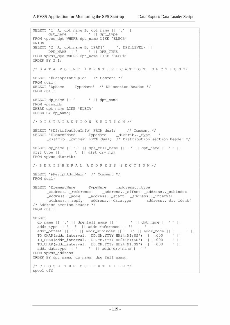
A PVSS Application for Monitoring the SPS Start-up Data Export: Data Loader Script
- 119 -
SELECT ’1’ A, dpt_name B, dpt_name || ’.’ || dpt_name || ’ ’ || dpt_typeFROM vpvss_dpt WHERE dpt_name LIKE ’ELEC%’UNIONSELECT ’2’ A, dpt_name B, LPAD(’ ’, DPE_LEVEL) || DPE_NAME || ’ ’ || DPE_TYPEFROM vpvss_dpe WHERE dpt_name LIKE ’ELEC%’ORDER BY 2,1;
/* D A T A P O I N T I D E N T I F I C A T I O N S E C T I O N */
SELECT ’#Datapoint/DpId’ /* Comment */FROM dual;SELECT ’DpName TypeName’ /* DP section header */FROM dual;
SELECT dp_name || ’ ’ || dpt_nameFROM vpvss_dpWHERE dpt_name LIKE ’ELEC%’ORDER BY dp_name;
/* D I S T R I B U T I O N S E C T I O N */
SELECT ’#DistributionInfo’ FROM dual; /* Comment */SELECT ’ElementName TypeName _distrib.._type ‘
_distrib.._driver' FROM dual; /* Distribution section header */
SELECT dp_name || '.' || dpe_full_name || ' ' || dpt_name || ' ' ||dist_type || ' \' || dist_drv_numFROM vpvss_distrib;
/* P E R I P H E R A L A D D R E S S S E C T I O N */
SELECT '#PeriphAddrMain' /* Comment */FROM dual;
SELECT 'ElementName TypeName _address.._type_address.._reference _address.._offset _address.._subindex_address.._mode _address.._start _address.._interval_address.._reply _address.._datatype _address.._drv_ident'
/* Address section header */FROM dual;
SELECT dp_name || '.' || dpe_full_name || ' ' || dpt_name || ' ' || addr_type || ' "' || addr_reference || '" ' || addr_offset || ' ' || addr_subindex || ' \' || addr_mode || ' ' || TO_CHAR(addr_interval, 'DD.MM.YYYY HH24:MI:SS') || '.000 ' || TO_CHAR(addr_interval, 'DD.MM.YYYY HH24:MI:SS') || '.000 ' || TO_CHAR(addr_interval, 'DD.MM.YYYY HH24:MI:SS') || '.000 ' || addr_datatype || ' "' || addr_drv_name || '"'FROM vpvss_addressORDER BY dpt_name, dp_name, dpe_full_name;
/* C L O S E T H E O U T P U T F I L E */spool off