A Prpgram for Shading Molecular Models Catherine Helen Johnson
108
DNIF77 A Prpgram for Shading Molecular Models by Catherine Helen Johnson An essay presented to the University of Waterloo in partial fulfillment of the requirements for the degree of Master of Mathematics in Computer Science Waterloo, Ontario, 1982 • C. H. Johnson
Transcript of A Prpgram for Shading Molecular Models Catherine Helen Johnson

DNIF77
A Prpgram for Shading Molecular Models
by
Catherine Helen Johnson
An essay
presented to the University of Waterloo
in partial fulfillment of the
requirements for the degree of
Master of Mathematics
in
Computer Science
Waterloo, Ontario, 1982
• C. H. Johnson
ACKNOWLEDGEMENTS
I am grateful to my supervisor, Professor Kellogg S. Booth, for providing both the topic of this essay and assistance in its development.
I wish also to thank the members of the Computer Graphics Laboratory, especially Paul Breslin and Darlene Plebon, for their advice concerning the Iko- nas 3000 frame buffer and its associated software.
DNIF77A Program for S h a d in g Molecular Models
1. Introduction
DNIF77 is a FORTRAN 77 extension of the original FORTRAN DNI program written by Nelson Max of Lawrence Livermore Laboratory as a post-processor to add colour shading and highlighting capability to the ATOMS program [Max79a, Max79b]. ATOMS produces monochrome colour perspective depictions of spacefilling and ball-and-stick crystal and molecular structures [Know77].
DNI generates a binary input tape for a minicomputer-controlled Dicomed D48 graphic film recorder, which plots directly on black and white or colour film at a maximum resolution of 4096 by 4096 pixels. Colour images are generated by multiply exposing the appropriate areas of the film at the desired brightness levels through a series of colour filters, one at a time; black and white pictures use only a neutral filter.
DNIF77 is capable of displaying its molecular input on or offline using an Ikonas 3000 frame buffer attached to a DEC PDP 11/45 computer running under the UNIX operating system. This configuration is a raster scan display with a two-dimensional array of 512 by 512 32-bit words of refresh memory representing each position, or pixel, on its screen. Each pixel contains a black and white greyscale or colour intensity level. More generally, an index into a colour lookup table specifies the desired colour of the corresponding location on the display screen. An important characteristic of frame buffer memory is its random accessibility.
This essay explains the shading algorithm of the original DNI program and describes the frame buffer implementation. It includes a discussion of goals, justification of the choice of source language, and an explanation of program input and all subroutines, outlines suggestions for performance optimization, and indicates areas of future development for which DNIF77 will provide the basis.
1

2
2. Shading and Highlighting in DNI (Dicomed Version)
Hiis computation is described in detail as background for the algorithm chosen for the frame buffer implementation.
ATOMS and ATOMLLL divide the visible segments of each atom (sphere) and bond (cylinder) into a set of trapezoids with straight vertical edges and curved or straight horizontal edges. DNI may thus conveniently shade these trapezoids in vertical segments.
The shading equations arise in the following way. For the sphere centred about the point C = {XC, YC, ZC). having radius R, with P = (X , Y, Z) some arbitrary point on its surface, one can derive the following equation:
cos'* = B*-(X-XC£-(Y-YC?
where iS = the angle of incidence of the light source with the sphere (assumed to originate from a point infinitely far behind the observer) [Max79a, Max79b].
Because the sphere’s constituent trapezoids have vertical sides for a particular vertical scan segment, R, X, XC, and YC are fixed constants in the above equation, which then reduces to a quadratic equation in Y. This quadratic is evaluated efficiently using the technique of finite differences.
If we let
/ (y) = coszi?
then
A/ = / (y + A) - / (y)
A2/ = / ( y + 2 / i ) - 2 / ( y + A ) + / ( y )
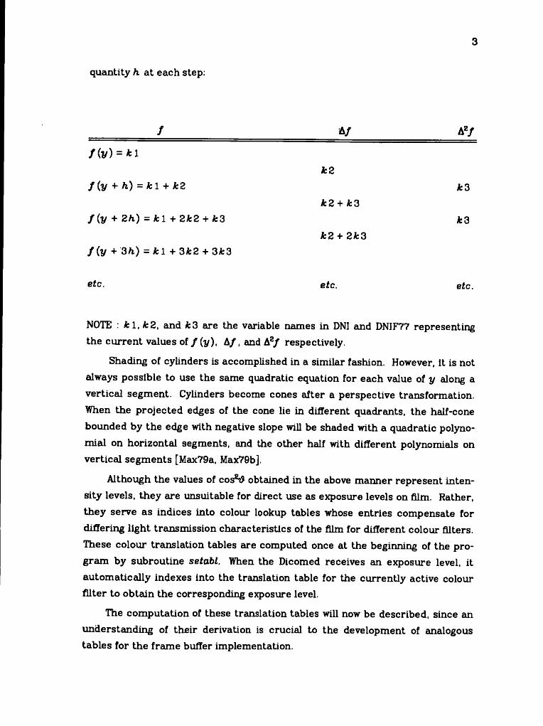
where A/ and A2/ are the first and second finite differences, respectively, and A2/ is a constant equal to /" (y ) when / (y) is a quadratic equation. The following tableau illustrates the evaluation of f (y) for y incrementing by some fixed
3
quantity h at each step:
/ ______________
f ( v ) = *1
f ( y + h) = A: 1 + k2
f ( y + 2h) = k l + 2k2 + Jfc3
f ( y + 3 h) = jfcl + 3k2 + 3A:3
etc.
&/
k2
k2 + k 3
k2 + 2k3
etc.
Az/
*3
*3
e£c.
NOTE : k l , k 2 , and *3 are the variable names in DNI and DNIF77 representing the current values of f ( y ) , A/, and A2/ respectively.
Shading of cylinders is accomplished in a similar fashion. However, it is not always possible to use the same quadratic equation for each value of y along a vertical segment. Cylinders become cones after a perspective transformation. When the projected edges of the cone lie in different quadrants, the half-cone bounded by the edge with negative slope will be shaded with a quadratic polynomial on horizontal segments, and the other half with different polynomials on vertical segments [Max79a, Max79b],
Although the values of cos2# obtained in the above manner represent intensity levels, they are unsuitable for direct use as exposure levels on film. Rather, they serve as indices into colour lookup tables whose entries compensate for differing light transmission characteristics of the film for different colour filters. These colour translation tables are computed once at the beginning of the program by subroutine setabl. When the Dicomed receives an exposure level, it automatically indexes into the translation table for the currently active colour filter to obtain the corresponding exposure level.
The computation of these translation tables will now be described, since an understanding of their derivation is crucial to the development of analogous tables for the frame buffer implementation.
4
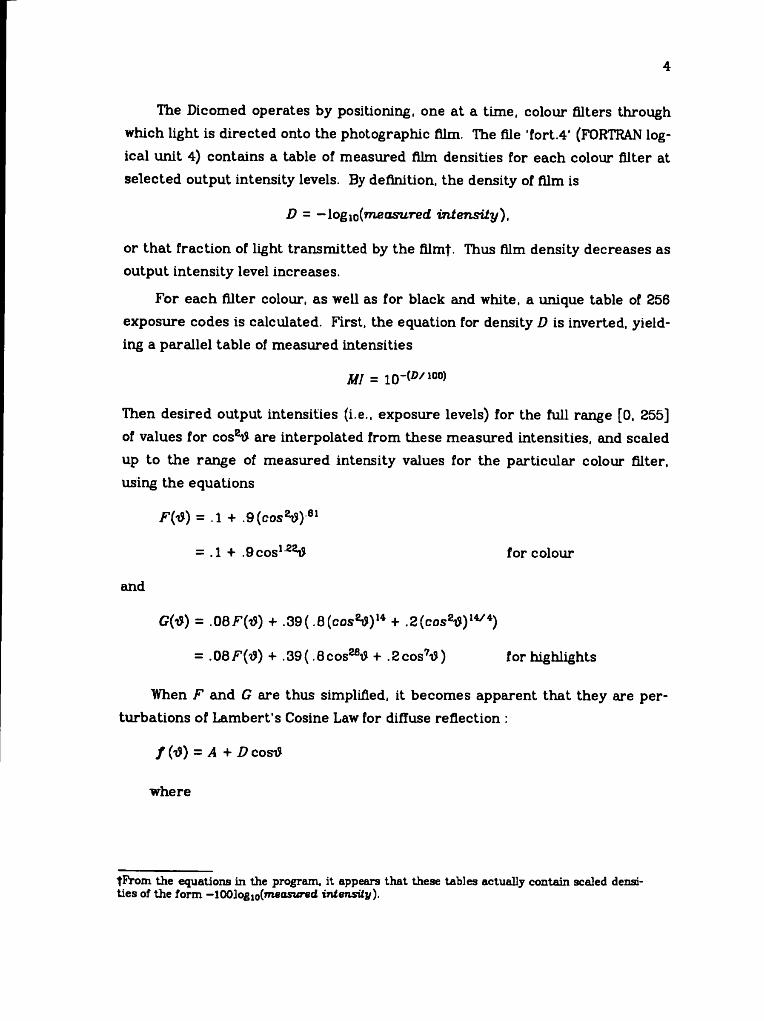
The Dicomed operates by positioning, one at a time, colour filters through which light is directed onto the photographic film. The file ‘fort.4’ (FORTRAN logical unit 4) contains a table of measured film densities for each colour filter at selected output intensity levels. By definition, the density of film is
D = -log^m easured intensity),
or that fraction of light transmitted by the film|. Thus film density decreases as output intensity level increases.
For each filter colour, as well as for black and white, a unique table of 256 exposure codes is calculated. First, the equation for density D is inverted, yielding a parallel table of measured intensities
MI = 10-^/10°)
Then desired output intensities (i.e., exposure levels) for the full range [0. 255] of values for cos8t) are interpolated from these measured intensities, and seeded up to the range of measured intensity values for the particular colour filter, using the equations
/ ’(tf) = .1 + .9(cos*i>)-ei
= .1 + .9 cos122i? for colour
and
Gi'd) = ,08F(o>) + .39 (.6 (cos8#)14 + ^ (cos8# )14̂ )
= .08/'’('$) + .39( .8cosza# + .2cos7/d) for highlights
When F and G are thus simplified, it becomes apparent that they are perturbations of Lambert’s Cosine Law for diffuse reflection :
/ (t?) = A + D cost?
where
tF rom the equations in the program, it appears th a t these tables actually contain scaled densities of the form — lOOlog^(measured intensity).
5
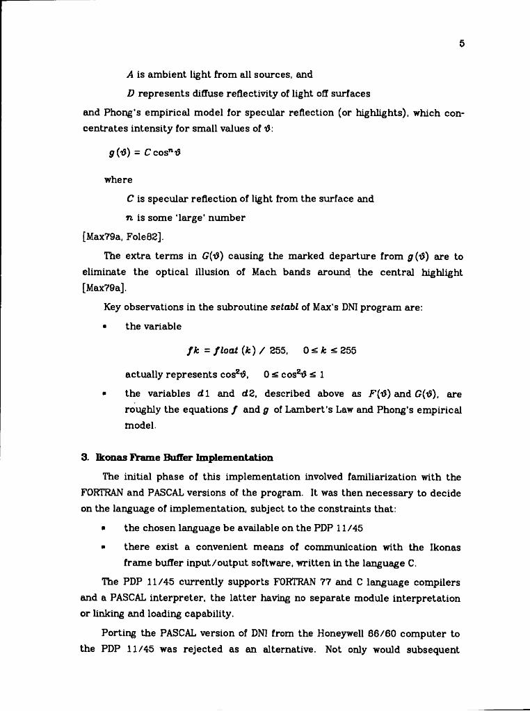
A is ambient light from all sources, and
D represents diffuse reflectivity of light off surfaces
and Phong’s empirical model for specular reflection (or highlights), which concentrates intensity for small values of d:
$(i$) = Ccosn,d
where
C is specular reflection of light from the surface and
n is some ‘large’ number
[Max79a, Fole82].
The extra terms in G(d) causing the marked departure from g (1S) are to eliminate the optical illusion of Mach bands around the central highlight. [Max79a].
Key observations in the subroutine setdbl of Max’s DNI program are:
■ the variable
f k = float (k ) / 255, 0 k < 255
actually represents cosztf, 0 < cosztf < 1
■ the variables d 1 and d2, described above as F{iS) and G(tf), are roughly the equations / and g of Lambert’s Law and Phong's empirical model.
3. Ikonas Frame Buffer Implementation
The initial phase of this implementation involved familiarization with the FORTRAN and PASCAL versions of the program. It was then necessary to decide on the language of implementation, subject to the constraints that:
■ the chosen language be available on the PDP 11/45
■ there exist a convenient means of communication with the Ikonas frame buffer input/output software, written in the language C.
The PDP 11/45 currently supports FORTRAN 77 and C language compilers and a PASCAL interpreter, the latter having no separate module interpretation or linking and loading capability.
Porting the PASCAL version of DNI from the Honeywell 66/60 computer to the PDP 11/45 was rejected as an alternative. Not only would subsequent
program development using the interpreter be tediously slow, but there is no way of calling C language routines directly from this implementation of PASCAL. A separate program would have to be written to transmit an output file from PASCAL DNI to the Ikonas.
The UNIX FORTRAN 77 compiler accepts FORTRAN as a subset, and permits separate module compilation and cedis to subroutines written in C. In addition, it produces the same intermediate language as the C compiler; C code generation, optimization, and execution time performance profiling capabilities eire thus accessible from FORTRAN 77. A further advantage of FORTRAN 77 is that it can directly produce a Dicomed input file in the required 16-bit binary format; the PASCAL version of the program used an intermediate step to translate ASCII output into 16-bit binary Dicomed input.
For all these reasons, it was decided to use FORTRAN 77 for the initial development of the frame buffer implementation The work required to get the original FORTRAN version of DNI running on the PDP 11/45 was minimal, as outlined in APPENDIX I. Certainly, translating the program to C is a better longterm solution. Performance would be improved, as high usage modules could be translated into microcode destined for residence in the Ikonas microprocessor memory.
Having obtained a FORTRAN 77 version of the program, extensive recoding was undertaken to modularize lengthy subroutines (main, trapez), eliminate 'do-nothing' code, define COMMON blocks in UNIX ‘include’ files, and take advantage of the if-then-else construct. At each stage of this revision, the Dicomed output files resulting from fixed test data were comp Eire d against output for the same data from the original program. A by-product of this activity was the detection of two bugs in the original version of DNIj\
The next phase of the project was to enhance DNI to produce both Dicomed and Ikonas output.
The orgemization of computation in DNI is determined strictly by the operating characteristics of the Dicomed film recorder. Highlighting must be performed as a separate pass over identical data, because the correct filter and colour translation table must be pre-selected prior to exposure of the film. The plotting resolution on the Dicomed is either 1024 by 1024, 2048 by 204B, or 4096tS ee APPENDIX I.
7
by 4096 pixels. At the lower resolutions, 'macro-pixels’ greater than 1 pixel in dimension are automatically shaded.
The following issues were addressed when introducing the frame buffer output capability to DNI:
■ desire to achieve output device independence until the lowest possible level of processing
■ selection and specification of an appropriate 'visible window' for display, given the maximum resolution of 512 by 512 pixels on the Iko- nas.
■ choice of an appropriate colour representation, given the facts that the Ikonas uses an RGB colour representation, and its colour display properties bear no resemblance to those of photographic film.
■ desire to produce a modular program useful as a tool for future investigation in such topics as anti-aliasing and colour shading and correction.
The methods chosen to handle these issues are described in the appropriate subroutine summaries of the following program documentation.
4. Program Documentation
4.1. Input
The molecular description file 'fort.9' (FORTRAN logical unit 9) is produced by ATOMLLL. It consists of 220 rows, each containing 10 integers in 10 i7 format.
These 220 rows correspond to the 11 arrays, each of length 200, belonging to COMMON block /PARAM/, contained in the file 'param.cm':
n, kt, kb, xl, xr, xct, yet, rt, xeb, ycb, rb.n(i) represents the record type, which is either a sphere (atom), cylinder (bond), trapezoid, end-of-frame, or end-of-job. The itfl elements of all 11 vectors in /PARAM/ comprise the complete set of given information about a specific object In the molecular description, and will subsequently be referred to as a record.
It should be noted that the interpretation of each field in a given record depends on that record’s type indicator, n(i). For instance, if n(i) indicates a trapezoid record, kt(i) describes its top arc, whereas kt(i) represents the colour of a spherical record.
6
In general, each cylinder or sphere record is followed by a list of its constituent trapezoid records. Next comes an end-of-frame record, and finally, an end-of-job record.
This knowledge was used to construct the admittedly artificial, but manageable input test files
/ u / chjohnson/ da ta / cyll
/cyl2
/sph2
These files represent, respectively, the horizontal and vertical cylinder and the large red sphere of Fig. 1 in APPENDIX VI.
4.2. Main Program
The main program controls the processing of the ATOMLLL-generated input data described in the previous section. Colour shading and highlighting are performed as two separate passes over the input data when Dicomed output is desired, or simultaneously for Ikonas frame buffer output.
Program activity falls very naturally into the categories of initialization, record processing, and output; it is within this functional framework that the subroutines comprising DNIF77 will be discussed.
4.3. Initialization
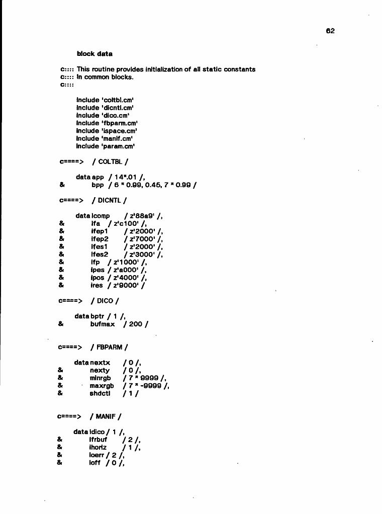
4.3.1. block data
This subroutine initializes all static constants in COMMON blocks at compile time.
4.3.2. init
This routine queries the user for program execution control parameters; recommended dialogues for both output devices are described in APPENDIX II. A feature of these dialogues is that they loop until valid responses are given. The control parameters are stored in the COMMON blocks /DEBUG/, /FBPARM/, and /PGMCTL/. Spacing constants and Dicomed control parameters dependent on the output device resolution are also calculated, and, for frame buffer output,
9
the subset of input data to be plotted is specified.
The latter point requires clarification. The Dicomed film recorder has a maximum resolution of 4096 by 4096 pixels, and a minimum resolution of 1024 by 1024 pixels, whereas the resolution of the Ikonas frame buffer is 512 by 512 pixels. Frame buffer output assumes a device resolution of 1024 (which may be altered by changing the values of the integers minxd, minyd, maxxd, and maxyd in the DATA statement at the beginning of the routine).
By default, the program will display on the Ikonas the 512 by 512 array of intensities calculated for that portion of the input data centred about the pixel location (512, 512). Optionally, the user may select any pixel location whose x and y coordinates are within the range [1, 1024] as the centre of his 'visible window'. When the chosen centre is too close to a boundary, the displayed picture will of course be smaller than 512 by 512 pixels.
4.3.3. setabl
This routine computes colour lookup tables indexable by values of cos2t? obtained as the solution to the quadratic shading equations. The purpose of these tables is to compensate for nonlinearities in colour perception on the output device, as well as the film, in the case of the Dicomed. There are significant differences in the tables used by the Dicomed and the Ikonas. The underlying derivation of tables for both devices is similar, although the task is simpler in the case of the Ikonas.
In the Ikonas implementation, Max's file of measured film densities is irrelevant, although some equivalent measure is desirable for gamma correction. Two tables are used — one for all colours and one for highlighting — representing the functions F(iS) and G(iS) described in Section 2. (These two tables could be combined into a single one by adding corresponding elements for colour and highlights and storing only the resulting sum). The table entries are scaled, not to the range of measured film densities, but rather, to the range [0, 255], on the assumption that the full 8-bit range of intensity for all colours was desiredf.
To simplify table lookup at the time exposure levels are emitted to the Ikonas, the function G is identically equal to 0 when the user requests notThis assumption could be altered b j defining different functions F for each colour.

10
highlighting of the displayed molecule.
4.3.4. reed
This routine reads the descriptions of visible molecules created by ATOMLLL into the 11 consecutive arrays of /PARAM/. The program depends on the fact that these arrays are consecutive, and declared in a specific fixed order. The conventions of FORTRAN 77 file I/O require that the input file 'fort.9' (FORTRAN logical unit 9) be rewound from its initial position at end-of-file prior to the issue of the read command.
4.4. Record Processing
No changes to this logic were necessitated by the addition of frame buffer output. Rather, the goal with this part of the program was to decompose it into functional modules.
4.4.1. begcyl
Originally part of the main program, this routine is called to initiate processing of cylinder (bond) records. A bug causing execution failure on input data containing only descriptions of bonds was corrected!. The cylinder top, bottom, and bisecting boundary line type, slope, and intercept are initialized, as are flags indicating the type of quadratic differencing and shading schemes to apply.
4.4.2. begsph
This routine performs an analogous function to begcyl for sphere (atom) records. Intermediate values required by the quadratic differencing equations are calculated.
4.4.3. newcol
This routine is called by begcyl and begsph to update information related to the colour of the object currently being shaded.
fSee APPENDIX I.

11
4.4.4. trapez
This routine controls the shading of all spheres and cylinders, which have been subdivided into trapezoids by the ATOMLLL pre-processor. It has been considerably shortened by extracting into separate modules sections representing specific shading strategies. The general tasks it performs include calculation of the radius and slope of the trapezoid top and bottom arcs. Then trapez sweeps horizontally across the trapezoid, calculating the number of scanlines to be shaded, and initially positioning the cursor at the first point to be plotted before calling the appropriate routine to shade the type of object from which the trapezoid arises.
4.4.5. shdsph
Originally part of trapez, this routine computes starting values for the quadratic differencing algorithm before passing control to quad to generate the required number of output intensities.
4.4.6. shdcyl
The complexity of shading cylinders is greater than that of shading spheres, as explained in Section 2.
First, the top, bottom, and middle coordinates of the bisecting (or highlighting) line are obtained. Different shading equations are required above and below this line, unless it is strictly vertical, in which case the entire trapezoid can be shaded using the same quadratic equation.
4.4.7. shdah, shdbh
Originally part of trapez, these routines shade a vertical scanline of a cylinder's trapezoid above or below its bisecting line, respectively, using a different quadratic equation on each successive horizontal line.
4.4.6. shvlinThis routine is a generalization of two nearly identical sections of code in
the original version of trapez. It is called to shade a vertical scanline above or below the bisecting line of a trapezoid using the same quadratic equation for the entire region; quad computes the desired intensities once the first and second differences are initialized. Note that only one of shdah and shvlin, and one of
12
shdbh and shulin is called to shade above and below the bisecting line, depending on the nature of the projected cylindrical image.
4.4.9. quad
This routine is an efficient implementation of the quadratic differencing algorithm described in Section 2. It packs two output intensities per word, requiring one division (or shift) and two additions to calculate each intensity.
4.5. Device Output
In extending the capability of DNI to produce frame buffer output, the underlying goal was to achieve some measure of device independence for out- putt- To this end, all calls in the original program to the routine dicowd were replaced by calls to output, with an additional parameter describing the nature of the data destined for output. For each type of data known to the routine, the appropriate action is taken, depending on the destination device. It is thus easy to add new devices to the program's repertoire.
4.5.1. output
When the Dicomed is the chosen output device, output passes the data directly to dicowd, or calls dicemp to flush the buffer of all accumulated exposure information. It is in the case of Ikonas output that the processing depends on the nature of the input to the routine.
The data type 'noop' is reserved for Dicomed control information; such data can be ignored when Ikonas output is selected.
Data flagged as the starting x or y plotting coordinate must be saved for future use once it has been scaled down from the range [l, 4096] used by the program for all pixel address computation^.
Exposure intensities destined for the Dicomed may be emitted either one ortwo per output data word. The frame buffer implementation must rememberthe format of the emitted data in order to unpack it, if generated by the routinequad, before translating it to the appropriate frame buffer representation. Thenumber of output exposure codes must also be saved so that the final exposurefThis is contrary to the suggestions in [YuenBO], which seem to imply eliminating any capability of producing Dicomed output in a frame buffer implementation.^Because this range is so deeply embedded in the Dicomed address calculation of the original DNI program, it is easier to perform this single rescaling for Ikonas output.
13
in packed format is ignored if this number is odd (a function performed automatically by the Dicomed hardware).
When output is called to emit an exposure level, it must first ensure that the destination pixel is within the frame buffer visible window. If so. the colour and highlight intensities corresponding to the input cos2# exposure level are obtained by table lookup in F(i?) and G(tJ), and converted to the colour representation required by the Ikonas display (three 8-bit bytes, right-justified, representing red, green, and blue components respectively, from the right side of the word). Shading and highlighting are thus performed in a single pass. The two intensities are simply added together one byte at a time to ensure that no byte exceeds the maximum permissable value of 255. Then the desired intensity is stored in a scanline buffer for transmission to the Ikonas.
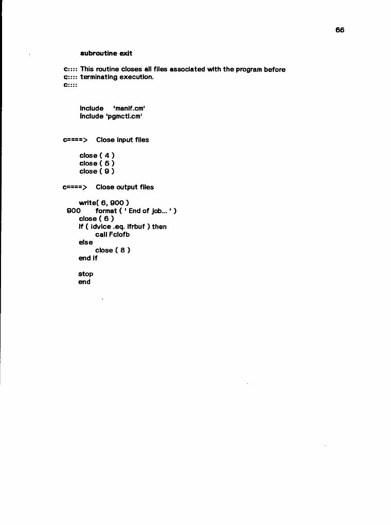
4.5.2. exit
This routine closes all input and output files before te rminating execution of the program.
4.5.3. Dicomed Output Support Routines
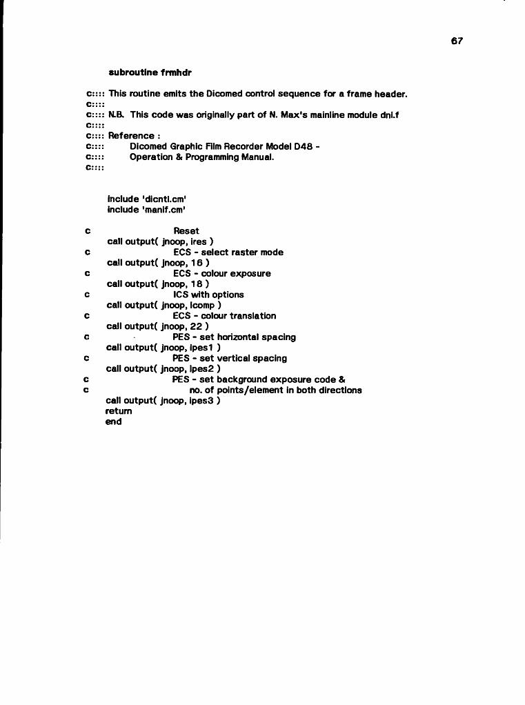
4.5.3.1. fnnhdr
This routine calls output to emit the sequence of Dicomed control commands required to set up a film frame header.
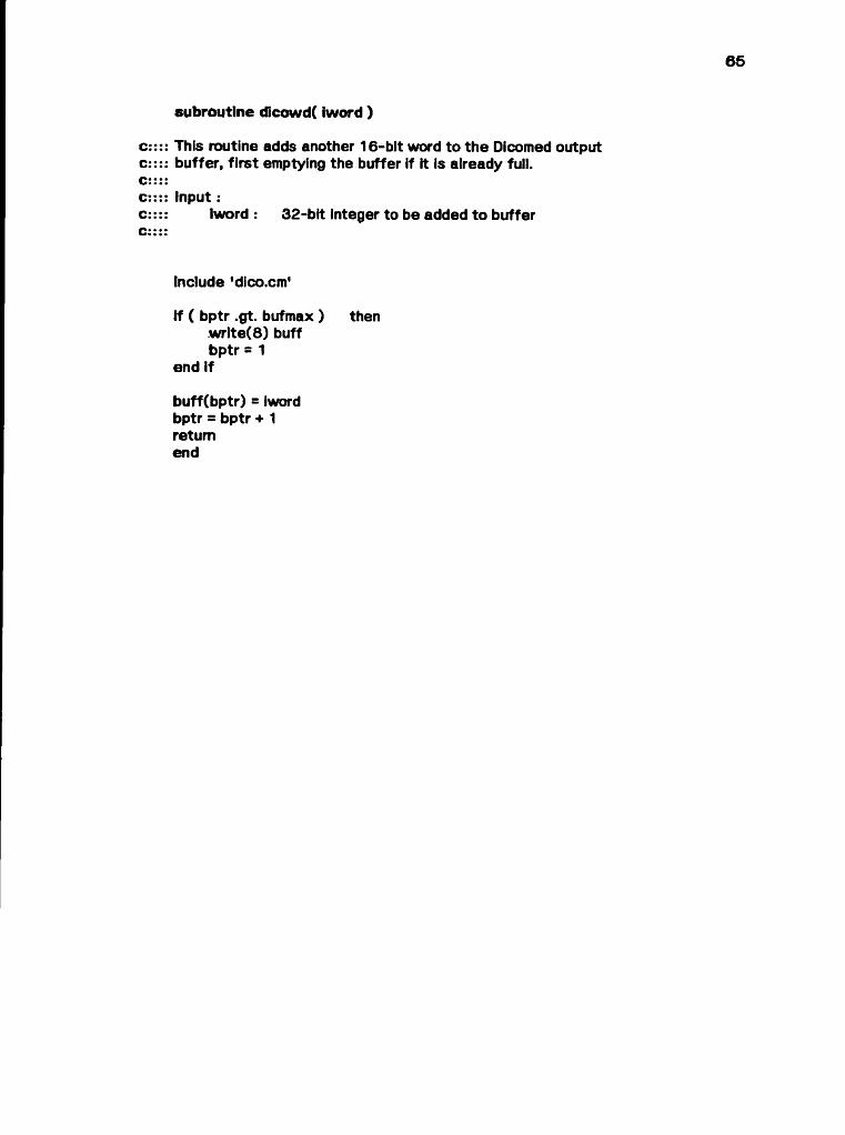
4.5.3.2. dicowd
This routine accumulates information destined for the Dicomed in a fixed- length buffer, emptying it to output file ’fort.8' (FORTRAN logical unit 8) as a binary stream of 16-bit integers when the buffer becomes full.
4.5.5.3. dicemp
This routine flushes the current contents of the Dicomed output buffer to the file ‘fort.8’.
14
4.5.4. Ikonas Output Support Routines
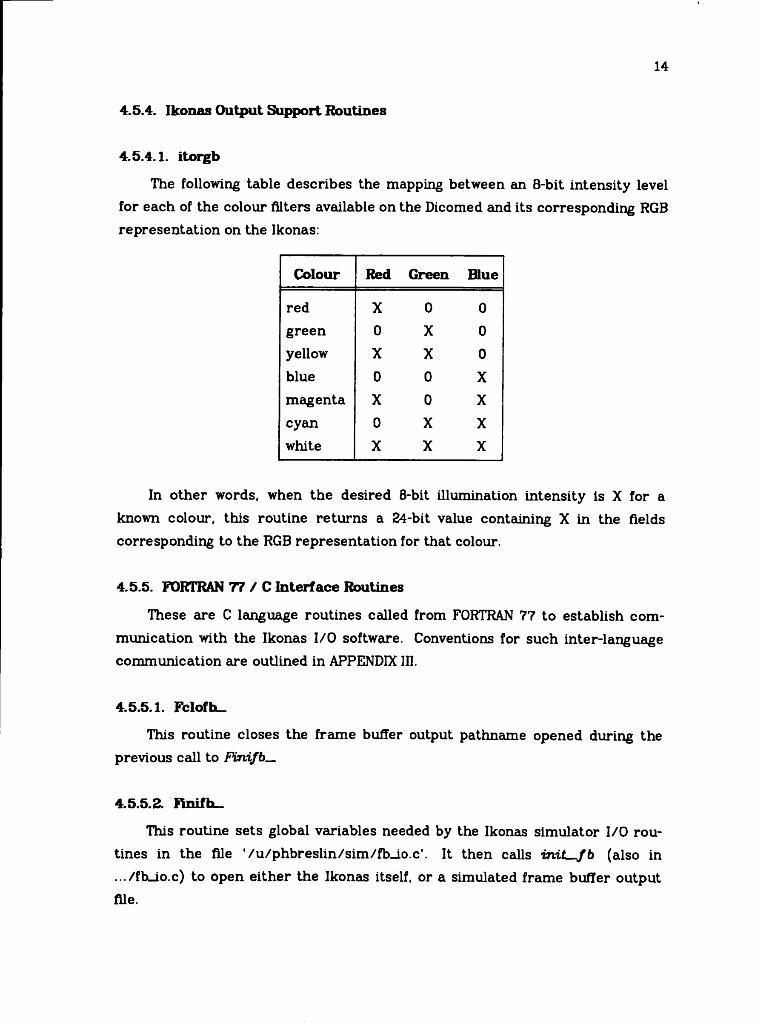
4.5.4.1. itorgb
The following table describes the mapping between an 8-bit intensity level for each of the colour filters available on the Dicomed and its corresponding RGB representation on the Ikonas:
Colour Red Green Blue
red X 0 0green 0 X 0yellow X X 0blue 0 0 Xmagenta X 0 Xcyan 0 X Xwhite X X X
In other words, when the desired 8-bit illumination intensity is X for a known colour, this routine returns a 24-bit value containing X in the fields corresponding to the RGB representation for that colour.
4.5.5. FORTRAN 77 / C Interface Routines
These are C language routines called from FORTRAN 77 to establish communication with the Ikonas I/O software. Conventions for such inter-language communication are outlined in APPENDIX III.
4.5.5.1. Fclofh—
This routine closes the frame buffer output pathname opened during the previous call to Fvnifb_
4.5.5.2. Rnifh_
This routine sets global variables needed by the Ikonas simulator I/O routines in the file ’/u/phbreslin/sim/fb_io.c’. It then calls in i t - fb (also in .../fbLio.c) to open either the Ikonas itself, or a simulated frame buffer output file.
15
4.5.5.S. fyutpx_
This routine converts arguments from their FORTRAN 77 type(s) to their expected C type(s) before calling a simulator routine to store a value in a specified pixel location.
4.5.5.4. get-storage
Also part of the simulator 1/0 package, this routine allocates a buffer one scanline long for frame buffer I/O.
5. DNIF77 Performance Optimization
The current version of the program is by no means optimal in terms of storage and CPU usage. Following are suggested approaches toward improving runtime performance.
(1) As described in Section 4.1, input data from ATOMLLL requires a central memory allocation of 3200 32-bit words, a very high proportion of which usually contain zeroes. Since the records spanning these 11 arrays are internally type-coded, including a special end-of-job record, there is no need for ATOMLLL to write out fixed blocks of input to DNIF77, aside from convenience as a magnetic tape format.
(2) Analysis of the results of running DNIF77 in frame buffer mode in conjunction with the UNIX performance profiler prof indicate a full 25% of execution time is spent performing integer division and multiplication. These operations simulate shifting and masking, both in the rescaling of data and packing more than one unit of information in a single word, as done by quad and itorgb. Any division or multiplication by a power of two could be replaced, either by a call to a C language function using
actual shift instructions, or ideally, a microprocessor-resident micro- coded version of such a C function. In fact, the same argument applies to all high-usage routines in the program (eg. output, itorgb, quax£).
(3) As noted in Section 4.3.3, the double lookup of colour and highlight intensities in routine output could be eliminated by storing the sum of these intensities in a single table. This would also significantly reduce the amount of shifting and masking performed, since the byte by byte addition of two RGB intensities from itorgb could be replaced by a single invocation of itorgb.
16
(4) A bottleneck in the current program is the sequence of subroutine calls
quad -* output I iiorgbFputpx
This sequence preserves the hierarchical nature of the processing, at the same time introducing redundant processing, quad packs two 6-bit intensity codes per word, which must immediately be unpacked by ouf- put. To eliminate this extra work and the overhead of several subroutine invocations, quad could be modified so that, for each 8-bit intensity code within the boundaries of the visible frame buffer window, the work of itorgb and Fputpx are performed by inline code. If such an approach were adopted, one would have to ensure that the inline and subroutine versions of this code always remained in step with each other.
(5) A problem arises due to the discrepancy in resolution of the Ikonas and Dicomed devices. It is often possible for an intensity to be calculated, only to be rejected for output to the frame buffer when the destination pixel is found to be outside the visible window. One could circumvent this situation by scaling all input data from ATOMLLL downward by a factor of two; however, this immediately creates a dual problem of multiple intensities calculated for the same pixel. Alternatively, program computations could be adjusted to permit 512 by 512 pixel resolution when the Ikonas frame buffer is the selected output device.
6. Areas of Future Development
6 .1. Colour S h a d in g and Correction
Comparison of output generated directly on the Ikonas monitor with the Polaroid photographs of APPENDIX VI reveals several ’features’.
Monitor output tends to exhibit a Mach band around the central highlights, which is removed by subsequent photographing of the generated image. This suggests that by modifying the terms added to the equation for G(tf) described in Section 2 to eliminate Mach bands in the Dicomed output, one could obtain a better quality image.
17
Photography of monitor output tends to blur the boundaries of atoms too quickly to black; this could possibly be improved by modifying the ambient light contribution in the equation for F(i>).
Another characteristic of frame buffer output is the high concentration of white light in the central highlight. This could be adjusted, for instance, by scaling the values of G(iJ) to some subrange of the full range of 256 possible intensities.
6 .2 . Ant ia l ia s in g
In general, the outer edges of all atoms (spheres) and bonds (cylinders), as well as all boundaries of their constituent trapezoids, should be antialiased. However, examination -of program output suggests several shortcuts can be taken. Natural boundaries of atoms and bonds appear smooth, as the calculated intensities fall off gradually to the background ambient lighting conditions. As well, neither shape of object exhibits internal faceting — i.e., we do not see the boundaries of the trapezoids from which an object is constructed. Based on these empirical observations, it appears that jagged lines in need of antialiasing correction occur where the natural boundary of an object is superimposed on another object. In other words, when an atom is occluded by either another atom or a bond, the trapezoid boundaries of the occluded portion of the atom require antialiasing.
Specific instances of candidates for antialiasing appear in the sample program output of APPENDIX VI. For example:
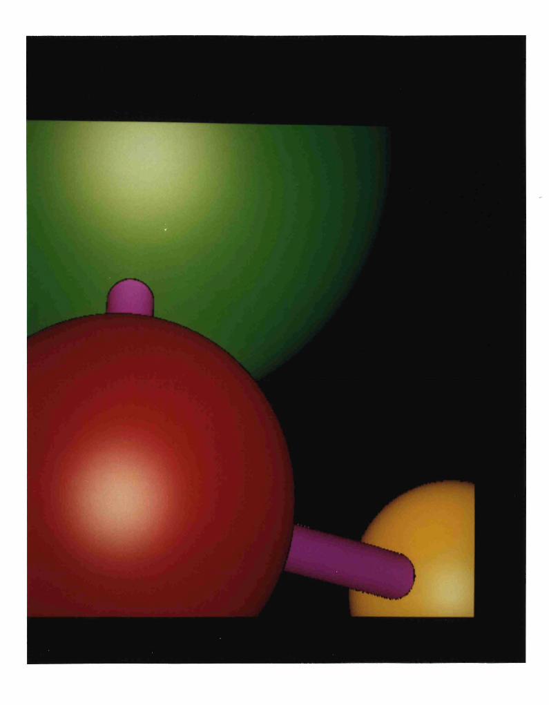
Fig. 1 : the top and bottom edges of trapezoids in the yellow atom which intersect with the bond
Fig. 2 : the intersections of the red and blue atoms
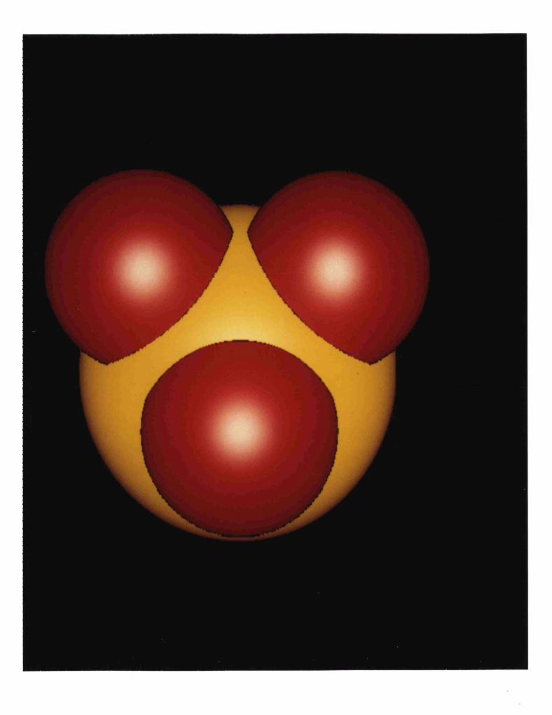
Fig. 3 : the intersections of the red and yellow atoms
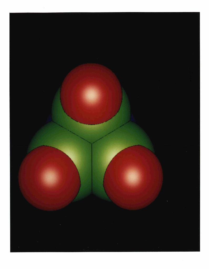
Fig. 4 : the non-vertical intersections of the green atoms with each other
To incorporate antialiasing into DNIF77, one must first devise a method of determining occluding trapezoid boundaries, perhaps by considering absolute changes in boundary slope between adjacent trapezoids of different objects. For the x and y coordinates thus selected, one could find the differences between their corresponding floating point and integer values. These differences could then be used as x and y coordinate input to shdsph or shdcyl to calculate an intensity by which the appropriate adjacent pixel would be fractionally

18
illuminated. Appropriate in this sense should be interpreted as x - 1 (y- 1) or x + 1 (y + 1), depending whether the difference between floating point and integer values of x (y) is less or greater than 0.5.
A limited form of antialiasing could be achieved by using the double resolution (1024 by 1024) information available from the colour shading computation. )l of the calculated intensity for each member of a group of four adjacent pixels could simply be added to produce the output intensity for the destination Ikonas pixel. More generally, any weighting function could be used to derive the individual contribution of each adjacent pixel to the final output intensity [Crow77]. No m atter what the selected antialiasing algorithm is, it should be microprocessor-resident to minimize its impact on total program execution time.
7. Conclusion
DNIF77 extends the capability of Nelson Max's DNI program to provide output for an Ikonas frame buffer. The shading algorithm of DNI was studied, and Ikonas colour lookup tables computed using a method similar to the derivation of those for the Dicomed. The approach works, but still requires refinement to obtain 'perfect' synthetically-generated molecules.
This essay documents the DNIF77 implementation, evaluates its performance, and suggests topics for further investigation, which should be facilitated by the modular organization of the program.
REFERENCES
Catm79
Crow77
Dico79
Feld78
Fole82
Know77
Max79a
Max79b
Yuen80
Catmull, E. "A tutorial on compensation tables,” Computer Graphics 13. 2 (Aug. 1979), 1-7.
Crow, F. C. "The aliasing problem in computer-generated shaded images," Communications of the ACM 2D, 11 (Nov. 1977), 799-805.
DICOMED Corporation. Graphic film recorder model D48 operation and programming manual. February 1979 edition, revision A.
Feldman, S. I., and Weinberger, P. J. "A portable FORTRAN 77 compiler,” Bell Laboratories, Murray Hill, New Jersey, Aug. 1978.
Foley, J. D., and Van Dam, A. Fundamentals of Interactive Computer Graphics, Addison-Wesley, Reading, Mass., 1982.
Knowlton, K., and Cherry, L. "ATOMS — a three-d opaque molecule system — for colour pictures of space-filling or ball-and-stick models,” Computers and Chemistry 1, 3 (1977), 161-166.
Max, N. "ATOMLLL — a three-d opaque molecule system, Lawrence Livermore Laboratory version," UCRL-52645, Lawrence Livermore Laboratory, University of California/Livermore, Jan. 1979.
Max, N. "ATOMLLL:- ATOMS with shading and highlights," Computer Graphics 13. 2 (Aug. 1979), 165-173.
Yuen, H. "PASCAL DNI, a program for shading molecular models," Master's Essay, Department of Computer Science. Faculty of Mathematics, University of Waterloo, 1980.
19

APPENDIX IAdaptation of DN1 to PORTEAN 77
1. Modifications
(1) ^include ‘filename’ was changed to include 'filename'
(2) Initialization of hexadecimal constants:
eg. zdOOO was changed to z’dOOO’
(3) The non-default logical input units 4 and 9 must be opened and rewound; they are otherwise positioned automatically at end-of-file.
(4) All calls to subroutine Ushift were replaced by division by 2.022 °.
2. Bugs Detected and Corrected
(1) the comma after column 72 in the declaration of COMMON block /isp / in the main program must be moved to the following line to be recognized; otherwise two variable names are concatenated, since intervening blanks and all information after column 72 are ignored by FORTRAN.
(2) the line ad = a / two 15 must be added following the call to newcol when beginning a new cylinder; otherwise the program fails if its only input is cylinder(s).
20

APPENDIX II DN1PV7 User's Guide
1. File Requirements in Current Directory
1.1. Dicomed or Ikonas Output
fort.9 t: input data generated by ATOMLLL
1.2. Dicomed Output
fort.4 : table of measured film densities
fort.8 : will be appended to unless removed from the current directory prior to execution of DNIF77
Notes:
(1) Both of the following dialogues may be carried out either interactively, or using a file of pre-determined responses, as In
dnif77 <dialogue_responses
(2) An invalid response to any query will regenerate the same question until an acceptable response is obtained.
2. Dialogue to Obtain Dicomed Output
User-supplied information appears in italics in the following dialogue.
dni/77Target output device:(l:Dicomed, 2:Ikonas) free format:1Wait between frames, double film advance, debug trace:(0:no, lyes) 3il format:
NNN|AH references to files named fort.n represent FORTRAN logical unit n.
21
22
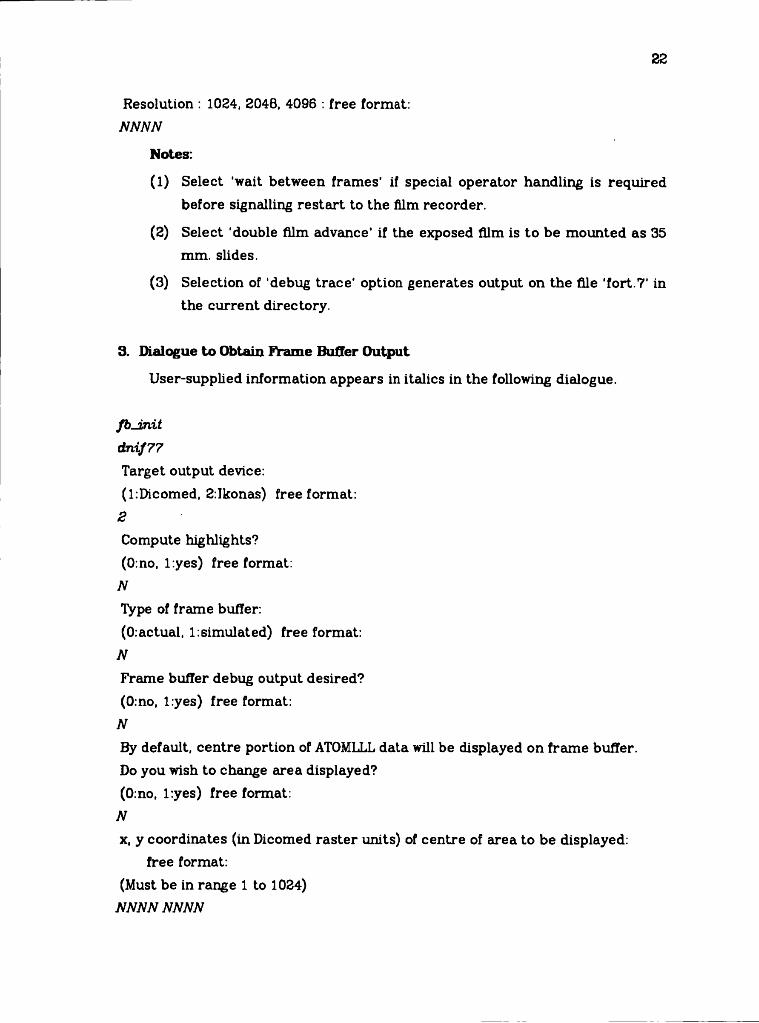
Resolution : 1024, 2048, 4096 : free format:NNNN
Notes:
(1) Select ’wait between frames’ if special operator handling is required before signalling restart to the film recorder.
(2) Select 'double film advance' if the exposed film is to be mounted as 35 mm. slides.
(3) Selection of 'debug trace' option generates output on the file 'fort.7’ in the current directory.
3. Dialogue to Obtain Frame Buffer Output
User-supplied information appears in italics in the following dialogue.
fb -in itdnif77Target output device:(l:Dicomed, 2:Ikonas) free format:
8Compute highlights?(0:no, lyes) free format:
NType of frame buffer:(0:actual, l:simulated) free format:
NFrame buffer debug output desired?(0:no, lyes) free format:
NBy default, centre portion of ATOMLLL data will be displayed on frame buffer.Do you wish to change area displayed?(0:no, lyes) free format:
Nx, y coordinates (in Dicomed raster units) of centre of area to be displayed:
free format:(Must be in range 1 to 1024)
NNNN NNNN

23
Notes:
(1) Atoms with no highlights will be shaded solid colours; highlighting adds white light radiating out from the angle of incidence of the user viewpoint with the surface of the display screen.
(2) It is useful to select simulated frame buffer output when a picture i9 desired quickly, or the frame buffer is in use. The resulting file can be displayed later, as explained below.
(3) Frame buffer debug output will appear on the file ‘fort.7’ in the current directory.
(4) The last question is asked only when the user indicates a desire to alter the default 'visible window'. Depending how close the chosen centre is to the boundaries of the ATOMLLL data, the dimension of the displayed region will be ^ 512 pixels in either direction.
3.1. Saving an Image Generated Directly on Ikonas Display
Issue the command/u/daplebon/bin/save_raster destination_save_file_name
3.2. Manipulation of Simulated Frame Buffer Output
A file called 'frame_buffer* will have been created in the current directoryduring execution of DNIF77. It can either be displayed on the Ikonas or examined interactively using the Ikonas simulator.
3.2.1. Displaying ’frame-buffer' on the Ikonas
Issue the command/u/ikonas/bin/draw_raster frame-buffer
3.2.2. Using the Ikonas Simulator
Issue the command/u/ikonas/bin/iksim +o
The +o option tells the simulator to use the existing file 'frame-buffer' as input.
The commands
SL scan y
8L x,y

24
permit examination of scanline y and pixel location (x, y) respectively.
exits the simulator. At this point, one can elect to save or release the file 'frame-buffer'. Since this file is very large, it should only be saved if absolutely necessary for later display or examination.

APPENDIX IDInterlanguage Co m m u n ic a tio n Between FORTRAN 77 and C
Following are the major factors to be considered when defining C procedures called from FORTRAN 77:
(1) The FORTRAN 77 statementcall f(x)
requires a corresponding C definition of a procedureU x )
(2) All FORTRAN 77 arguments to subroutines and functions are passed by address. Hence they must be declared as pointers to variables of the appropriate types within the called C procedures.
(3) The returned type of a C function called from FORTRAN 77 must be declared in the calling routine. For such declarations, the reader is referred to the table of corresponding FORTRAN 77 and C declarations in the FORTRAN 77 User's Guide [Feld78].
25
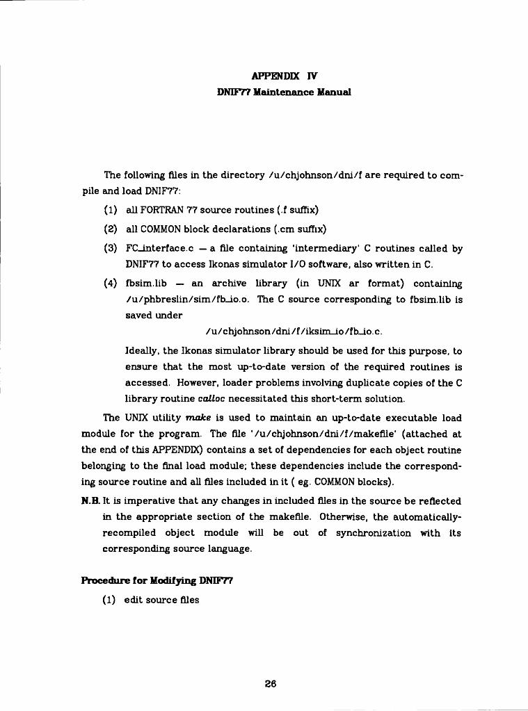
APPENDIX IVDNiîyy Maintenance Manual
The following files in the directory /u/chjohnson/dni/f are required to compile and load DNIF77:
(1) all FORTRAN 77 source routines (.f suffix)
(2) all COMMON block declarations (.cm suffix)
(3) FC_interface.c — a file containing 'intermediary' C routines called by DNIF77 to access Ikonas simulator I/O software, also written in C.
(4) fbsim.lib — an archive library (in UNIX ar format) containing /u/phbreslin/sim/fb_io.o. The C source corresponding to fbsim.lib is saved under
/u/chjohnson/dni /f/iksim_io /f h_io. c.
Ideally, the Ikonas simulator library should be used for this purpose, to ensure that the most up-to-date version of the required routines is accessed. However, loader problems involving duplicate copies of the C library routine calloc necessitated this short-term solution.
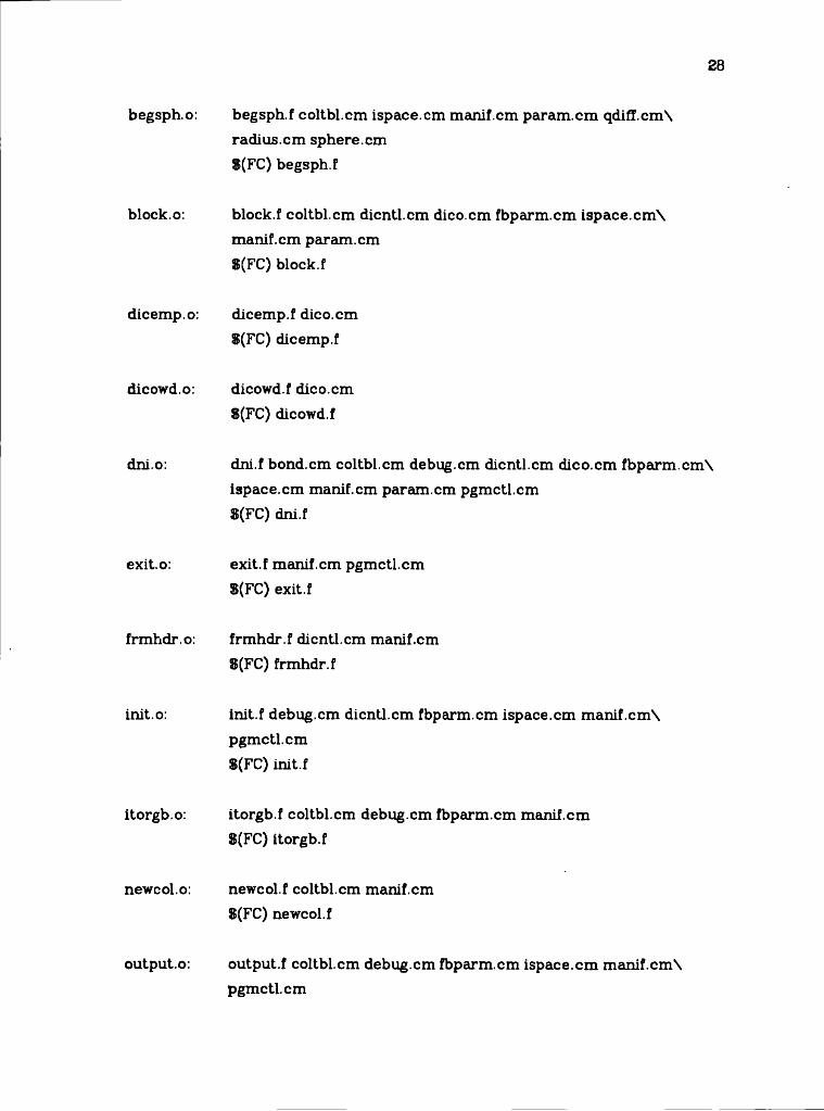
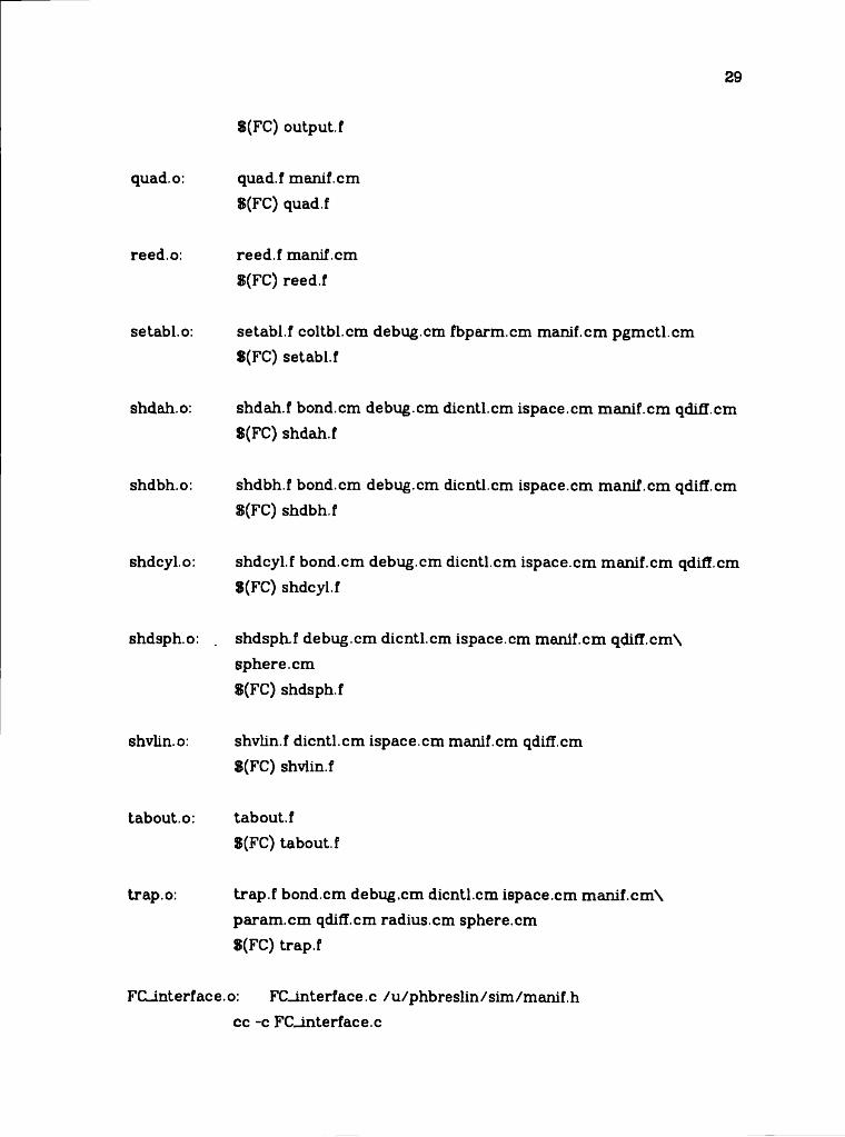
The UNIX utility make is used to maintain an up-to-date executable load module for the program. The file '/u/chjohnson/dni/f/makefile’ (attached at the end of this APPENDIX) contains a set of dependencies for each object routine belonging to the final load module; these dependencies include the corresponding source routine and all files included in it ( eg. COMMON blocks).
N.B. It is imperative that any changes in included files in the source be reflected in the appropriate section of the makefile. Otherwise, the automatically- recompiled object module will be out of synchronization with its corresponding source language.
Procedure for Modifying DNIKyy
(1) edit source files
26
27
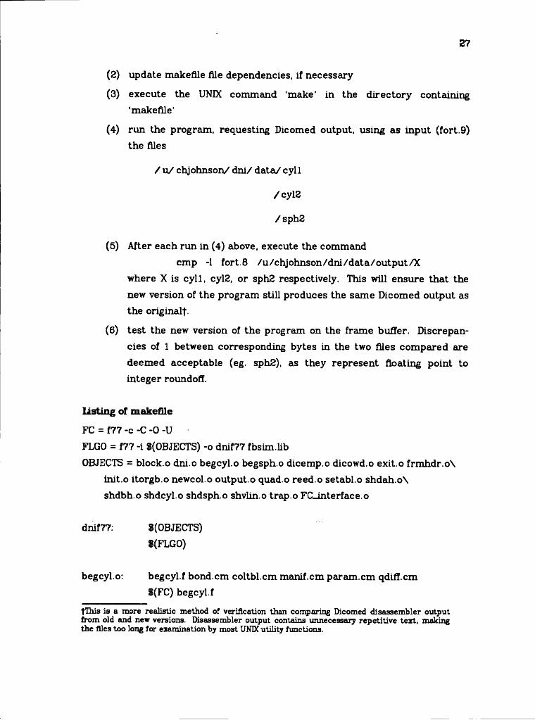
(2) update makefile file dependencies, if necessary
(3) execute the UNIX command 'make' in the directory containing 'makefile'
(4) run the program, requesting Dicomed output, using as input (fort.9) the files
/ u / chjohnson/ dni/ data/ cyll
/cyl3
/sph2
(5) After each run in (4) above, execute the commandcmp -1 fort.8 /u/chjohnson/dni/data/output/X
where X is cyll, cyl2, or sph2 respectively. This will ensure that the new version of the program still produces the same Dicomed output as the originalt.
(6) test the new version of the program on the frame buffer. Discrepancies of 1 between corresponding bytes in the two files compared are deemed acceptable (eg. sph2), as they represent floating point to integer roundoff.
Listing of makefile
FC = f77 -c -C -0 -UFLGO = f77 -i $(OBJECTS) -o dnif77 fbsim.libOBJECTS = block.o dni.o begcyl.o begsph.o dicemp.o dicowd.o exit.o frmhdr.o\
init.o itorgb.o newcol.o output.o quad.o reed.o setabl.o shdah.o\ shdbh.o shdcyl.o shdsph.o shvlin.o trap.o FC_interface.o
dnif77: »(OBJECTS)8(FLG0)
begcyl.o: begcyl.f bond.cm coltbl.cm manif.cm param.cm qdiff.cm8(FC) begcyl.f
fThis is a more realistic method of verification than comparing Dicomed disassem bler output from old and new versions. Disassembler output contains unnecessary repetitive text, making the files too long far examination by most UNIX utility functions.
26
begsph.o: begsph.f coltbl.cm ispace.cm manif.cm param.cm qdifl.cm\ radius.cm sphere.cm 8(FC) begsph.f
block.o: block.f coltbl.cm dicntl.cm dico.cm fbparm.cm ispace.cm\ manif.cm param.cm S(FC) block.f
dicemp.o: dicemp.f dico.cm 8(FC) dicemp.f
dicowd.o: dicowd.f dico.cm 8(FC) dicowd.f
dni.o: dni.f bond.cm coltbl.cm debug.cm dicntl.cm dico.cm fbparm.cm\ ispace.cm manif.cm param.cm pgmctl.cm 8(FC) dni.f
exit.o: exit.f manif.cm pgmctl.cm 8(FC) exit.f
frmhdr.o: frmhdr.f dicntl.cm manif.cm 8(FC) frmhdr.f
init.o: init.f debug,cm dicntl.cm fbparm.cm ispace.cm manif.cm\pgmctl.cm8(FC) init.f
itorgb.o: itorgb.f coltbl.cm debug.cm fbparm.cm manif.cm 8(FC) itorgb.f
newcol.o: newcol.f coltbl.cm manif.cm 8(FC) newcol.f
output.o: output.f coltbl.cm debug.cm fbparm.cm ispace.cm manif.cmN pgmctlcm
29
quad.o:
$(FC) output, f
quad.f manif.cm 8(FC) quad.f
reed.o: reed.f manif.cm 8(FC) reed.f
se tabi, o: setabl.f coltbl.cm debug.cm fbparm.cm manif.cm pgmctl.cm 8(FC) setabl.f
shdah.o: shdah.f bond.cm debug.cm dienti.cm ispace.cm manif.cm qdifl.cm 8(FC) shdah.f
shdbh.o: shdbh.f bond.cm debug.cm dienti.cm ispace.cm manif.cm qdifl.cm S(FC) shdbh.f
shdcyl.o: shdcyl.f bond.cm debug.cm dicntl.cm ispace.cm manif.cm qdifl.cm 8(FC) shdcyl.f
shdsph.o: shdsph-f debug.cm dicntl.cm ispace.cm manif.cm qdiff.cm\ sphere, cm 8(FC) shdsph.f
shvlin.o: shvlin.f dicntl.cm ispace.cm manif.cm qdifl.cm 8(FC) shvlin.f
tabout.o: tabout.f 8(FC) tabout.f
trap.o: trap.f bond.cm debug.cm dicntl.cm ispace.cm manif.cm\ param.cm qdifl.cm radius.cm sphere.cm 8(FC) trap.f
FCLinterface.o: FCLinterface.c /u/phbreslin/sim/manif.hcc -c FCLinterface.c
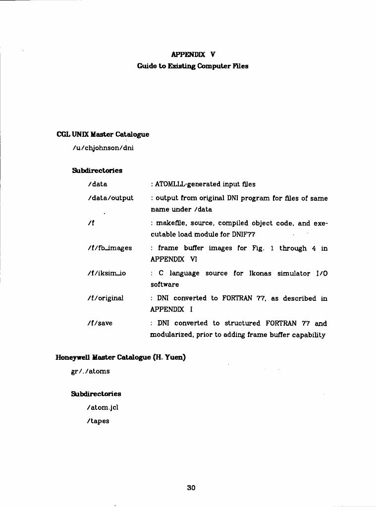
APPENDIX VGuide to Ewsting Computer flies
CGL UNIX Master Catalogue
/u/chjohnson/dni
Subdirectories
/data : ATOMLLL-generated input files
/data/output : output from original DNI program for files of same name under /data
/f : makefile, source, compiled object code, and executable load module for DNIF77
/f/fb_images : frame buffer images for Fig. 1 through 4 in APPENDIX VI
/f/iksim_io : C language source for Ikonas simulator I/O software
/f/original : DNI converted to FORTRAN 77, as described in APPENDIX I
/f/save : DNI converted to structured FORTRAN 77 and modularized, prior to adding frame buffer capability
Honeywell Master Catalogue (H. Yuen)
gr/./atom s
Subdirectories
/atom.jcl
/tapes
30

31
/dni.jcl
/c.progs
/essay
/atom, in
/source
/dm. in
f lie s
/new.l, /new.2: his Fig. 3f
/new.3, /new.4: his Fig. 5
/new.5, /new.6: his Fig. 4
/fort09: his Fig. 2
/ft09: his Fig. 1
VAX Master Catalogue
/u/cgl
Subdirectory
/chjohnson: Versatec plotter vtrofl format input text for this document
ffYuenBO].
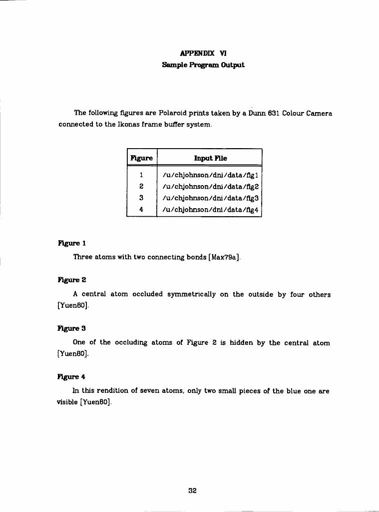
APPENDIX VI Sample Program Output
The following figures are Polaroid prints taken by a Dunn 631 Colour Camera connected to the Ikonas frame buffer system.
figure Input file
1 /u/chj ohnson/dni / data/fig 12 /u/chjohnson/dni/data/fig23 /u/chjohnson/dni/data/flg34 /u/chjohnson/dni/data/flg4
figure 1
Three atoms with two connecting bonds [Max79a].
figure 2
A central atom occluded symmetrically on the outside by four others [Yuen80].
figure 3
One of the occluding atoms of Figure 2 is hidden by the central atom [YuenBO].
figure 4
In this rendition of seven atoms, only two small pieces of the blue one are visible [YuenBO].
32

APPENDIX VD Program listings
(1) COMMON blocks—alphabetical order
(2) Main program—file dni.f
(3) FORTRAN 77 subroutines—alphabetical order
(4) C procedures—files FC-interface.c, iksim_io/fb_io.c
37
«ò «8 «9 «8
38
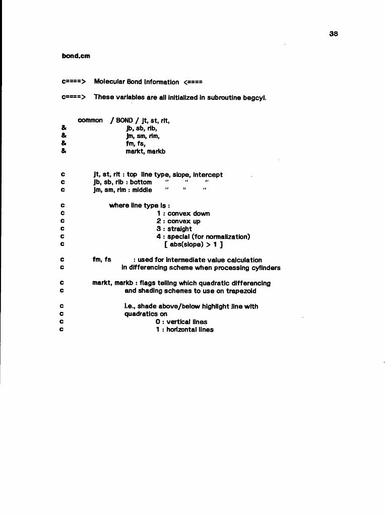
bond.cm
c====> These variables are all Initialized in subroutine begcyl.
c====> Molecular Bond Information <====
common / BOND / Jt, St, rlt, Jb, sb, lib,Jm, sm, rim, fm, fs,markt, markb
c jt, st, rlt: top line type, slope, interceptc Jb, sb, rib : bottom .......................c Jm, sm, rim: middle " "
cccccc
where line type Is :1 : convex down2 : convex up3 : straight4 : special (for normalization)
[ abs(slope) > 1 ]
c fm, fs : used for Intermediate value calculationc in differencing scheme when processing cylinders
c markt, markb : flags telling which quadratic differencingc and shading schemes to use on trapezoid
c i.e., shade above/below highlight line withc quadratics onc 0 : vertical linesc 1 : horizontal lines

•B «8 «8
eoltbl.cm
common / COLTBL / app, bpp, nowcol,Ihilit
c====> Colour Intensity Tables <====
dimension app(7,2),& bpp(7, 2)
c app : minimum Intensity (initialized in block data ic bpp : range of intensity ................. .
c wherec row index: coloursc 1 : redc 2 : greenc 3 : yellowc 4 : bluec 6 : magentac 6 : cyanc 7 : neutralc column index : shadingc 1 : colourc 2 : black & white
c nowcol colour of object currently being plottedc (set in subroutine newcol)c ihilit ; colour (1) or highlight (2) computationc (set in main program)

o o
40
c===> Debug control flags <====
common / DEBUG / Idbg,& Ifbdbg
c idbg : general trace & dump of calculated values
c ifbdbg : frame buffer debug information
0 : off1 : on
debug.cm
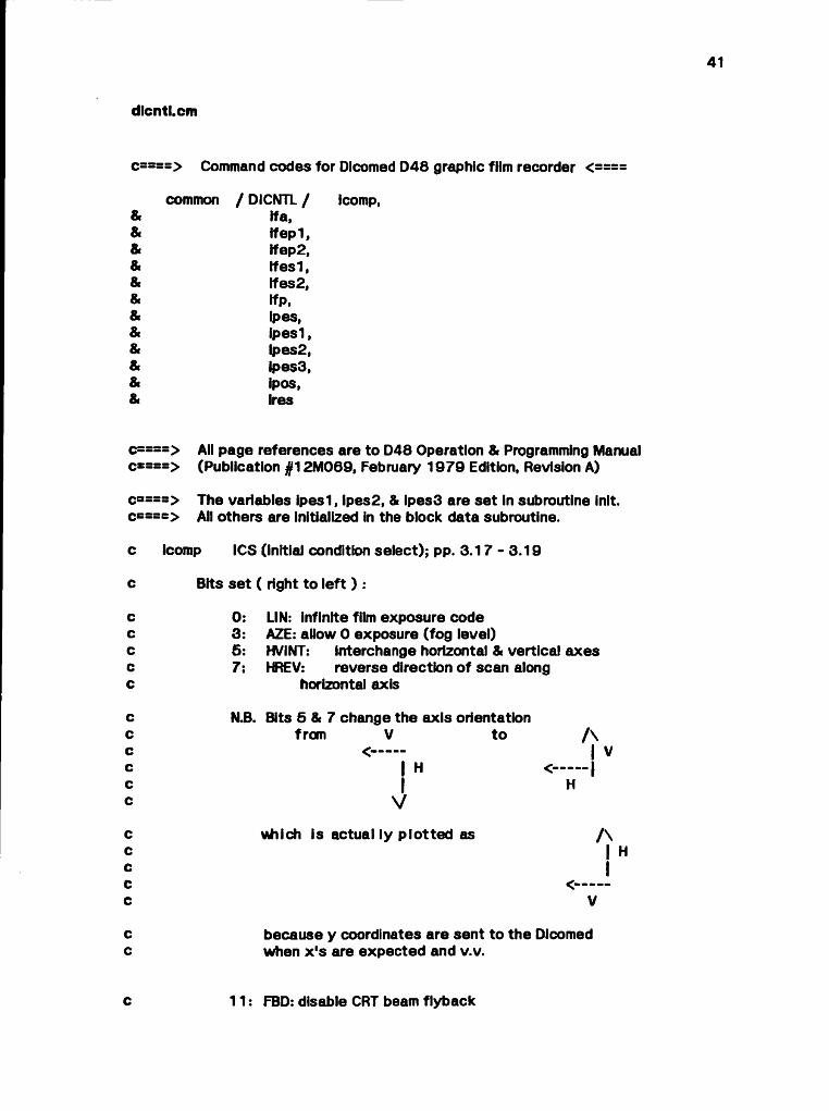
dlcntl.cm
common / DICNTL / Icomp, ifa, ifepl, tfep2,Ifesl, tfes2, ifp, ipes, ipesl,Ipes2, lpe$3, ipos, ires
c====> Command codes for Dlcomed D48 graphic fiim recorder <====
c====> All page references are to D48 Operation & Programming Manual c*===> (Publication #12M069, February 1979 Edition, Revision A)
c====> The variables ipesl, Ipes2, & ipes3 are set in subroutine init. c====> All others are initialized in the block data subroutine.
c icomp ICS (initial condition select); pp. 3 .17 - 3.19
c Bits se t ( right to left ) :
c 0; LIN: infinite film exposure codec 3: AZE: allow 0 exposure (fog level)c 5: HVINT: Interchange horizontal & vertical axesc 7: HREV: reverse direction of seem alongc horizontal axis
c N.B. Bits 5 & 7 change the axis orientationc from V to / \c <------ | Vc | H <------ 1c j Hc V
c which is actual ly plotted as / \c | Hc Ic <------C V
c because y coordinates are sent to the Dicomedc when x's are expected and v.v.
c 11: FBD: disable CRT beam flyback

oo
o
o o
o o
o o
o o
o o
o o
o o
o
no
n
o
42
If a EFS (exposure & filter select); p. 3.21no change of filter, no film advance, exposure level 0
Ifepl FES (function element select); pp. 3.8 - 3.14 (Always followed by ifep2)
Ifep2 FES function code 3 & ES set; p. 3.12plot the single intensity in the following word
Ifesl FES(Always followed by Ifes2)
no deferred status, filter code, film advance, exposure code
Ife82 FES function code 1 & ES sethorizontal raster line will be plotted from the following input stream, containing exposure codes packed 2 / word.
Ifp function 3 output formatcontains parameters to plot 1 element in direction 0 (positive horizontal) at the exposure level in bits 0-7 with no change of filter.
Ipes PES (point element select); p. 3.20
ipeslhorizontal element spacing 1 - 4 raster units horizontal point spacing 1 raster unit
Ipes2vertical element & point spacing (same as horizontal)
c Ipes3 c c c
background exposure code 0;no. of horizontal points/element = no. of verticalpoints/element = 1 ,2 , or 4 (depending on resolution)
c ipos VPA (vector or position absolute); p. 3.16 c moves CRT beam to position specified by absolutec horizontal & vertical coordinates;c uses previously-defined exposure code + 2 words:c 1 st - abs. horizontal 2nd - abs. vertical coordinate
c Ires ICS (initial condition select); pp. 3.17 - 3.19 c reset D48 to basic operating state described on p. 3-33

8» fi
»
43
dico.cm
c—==> Dicomed 16-blt output code buffers <====
common / DICO / buff, bptr, bufmax
lnteger*2 buff(200)
Integer bptr,& bufmax
c buff : output buffer; dumped to outputc file when fullc (set by subroutine dicowd)
c bptr : pointer to next available slotc in buffc (initialized In block data subroutine;c updated by subroutine dicowd)
c bufmax dimension of buffc (defined in block data subroutine)
9>9>
9>9»
9>9>
8»
9» fi*
9» 8«
8» *>
9» 8»
8» «
• 8» 8
» 8» 8
» 8» 9
» 8» 9
» 8» 8
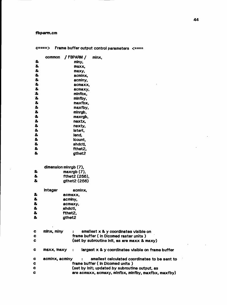
*fbparm .cm
common / FBPARM / minx, miny,maxx,maxy,acminx,acminy,acmaxx,acmaxy,mlnfbx,mlnfby,maxfbx,maxfby, mlnrgb, maxrgb,nextx,nexty,(start, lend,Icount, shdctl, fthet2, gthet2
c====> Frame buffer output control parameters <====
dimension mlnrgb (7), maxrgb (7), fthet2 (256), gthet2 (256)
integer acminx,acmaxx, acminy,acmaxy, shdctl, fthet2, gthet2
c minx, minycc
smallest x & y coordinates visible on frame buffer ( in Dicomed raster units )(set by subroutine Init, as are maxx & maxy)
c maxx, maxy largest x & y coordinates visible on frame buffer
c acminx, acminy smallest calculated coordinates to be sent toc frame buffer ( In Dicomed units )c (set by Init; updated by subroutine output, asc are acmaxx, acmaxy, minfbx, mlnfby, maxfbx, maxfby)
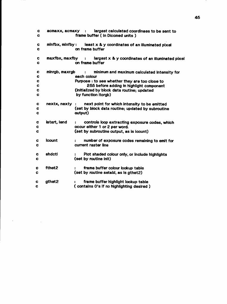
acmaxx, acmaxy largest calculated coordlnaes to be sent toframe buffer ( In Dicomed units )
mlnfbx, minfby: least x & y coordinates of an illuminated pixelon frame buffer
maxfbx, maxfby largest x & y coordinates of an illuminated pixelon frame buffer
minrgb, maxrgb minimum and maximum calculated intensity foreach colourPurpose : to see whether they are too close to
265 before adding in highlight component (Initialized by block data routine; updated by function itorgb)
nextx, nexty : next point for which intensity to be emitted(set by block data routine; updated by subroutine output)
is tart, lend controls loop extracting exposure codes, whichoccur either 1 or 2 per word.(set by subroutine output, as is Icount)
Icount number of exposure codes remaining to emit forcurrent raster line
shdctl : Plot shaded colour only, or include highlights(set by routine init)
fthet2 frame buffer colour lookup table(set by routine setabl, as is gthet2)
gthet2 frame buffer highlight lookup table( contains 0's if no highlighting desired )
00 00 00 00 00 00 00 o
oo
oo
oo
oo
46
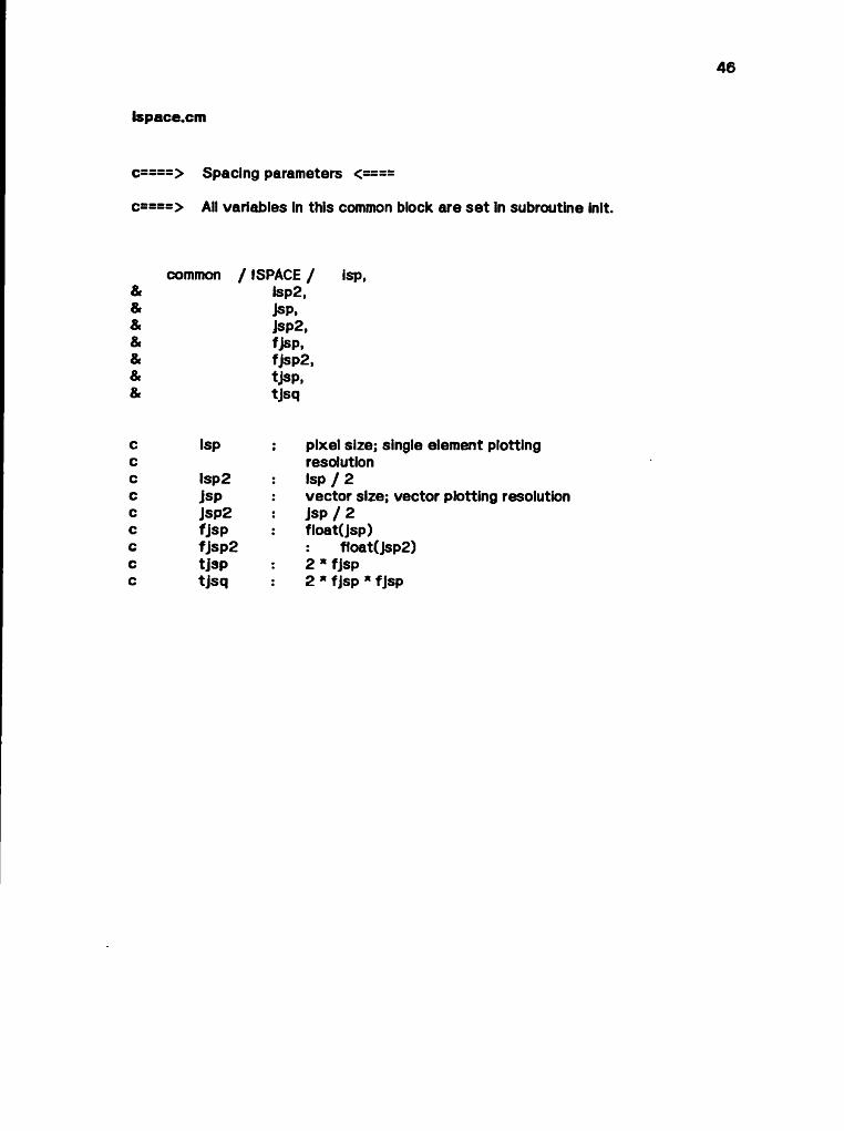
ispace.cm
c====> Spacing parameters <====
c====> All variables In this common block are se t In subroutine init.
common / ISPACE / isp, Isp2, jsp,jsp2,fjsp,fjsp2,tjsp,tjsq
Isp : pixel size; single element plotting resolution
Isp2 Isp / 2jsp vector size; vector plotting resolutionJsp2 Jsp / 2fjsp : float(jsp)fjsp2 f1oat(jsp2)tjsp 2 * fjsptjsq 2 * fjsp * fjsp
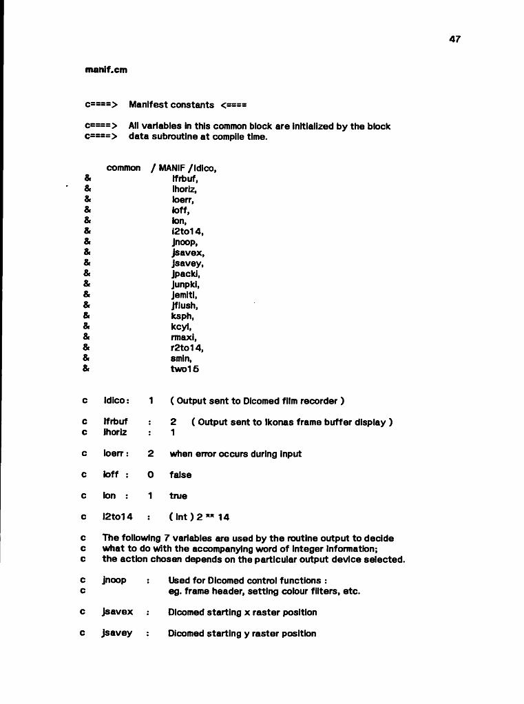
matiif.cm
c====> All variables in this common block are initialized by the block c====> data subroutine at compile time.
c====> Manifest constants <====
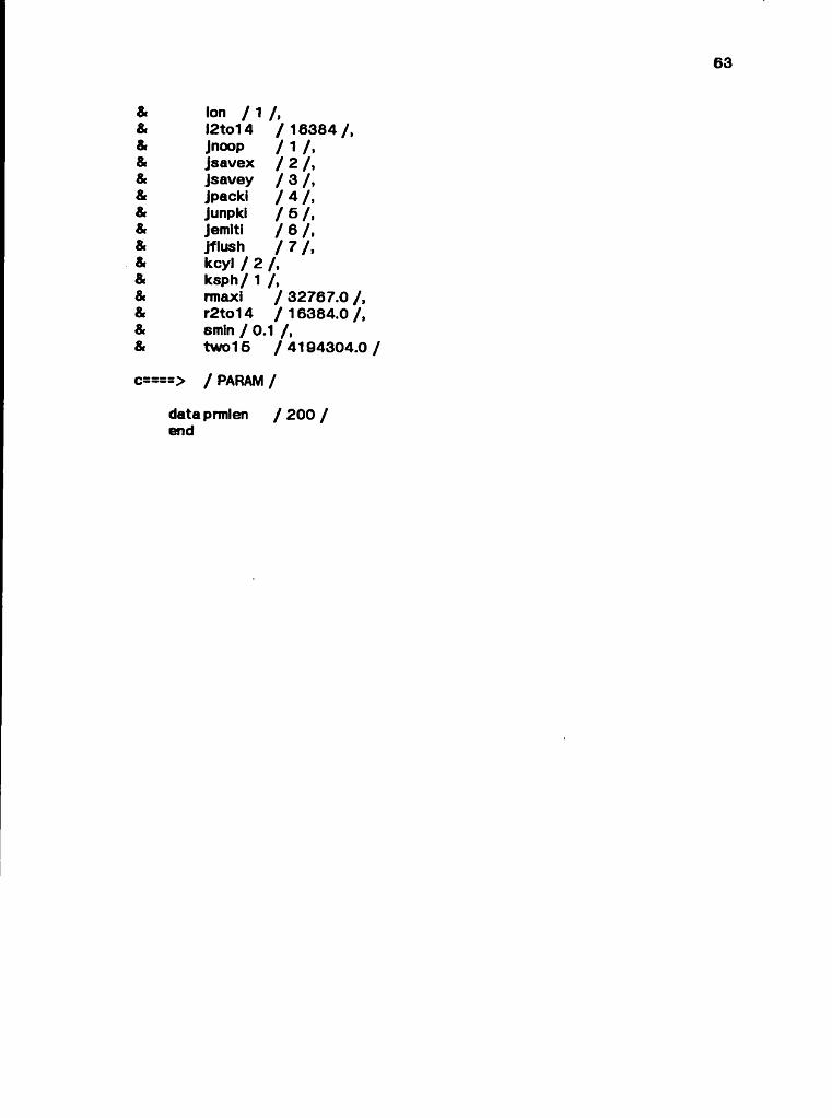
common / MANIF /Idico, Ifrbuf, ihoriz, ioerr, toff, ton,i2to14,Jnoop,jsavex,Jsavey,jpacki,Junpki,jemlti,Jflush,ksph,kcyl,rmaxi,r2to14,smin,two15
c idico : 1 ( Output sent to Dlcomed film recorder )
c ifrbuf ; 2 ( Output sent to Ikonas frame buffer display )c ihoriz : 1
c toerr : 2 when error occurs during input
c toff : 0 false
c ton : 1 true
c i2to14 : ( Int ) 2 ** 14
c The following 7 variables are used by the routine output to decidec what to do with the accompanying word of integer Information;c the action chosen depends on the particular output device selected.
c jnoop : Used for Dicomed control functions :c eg. frame header, setting colour filters, etc.
c Jsavex : Dicomed starting x raster position
c jsavey ! Dicomed starting y raster position

o a
48
c jpacki 2 Dicomed output intensities / word, right-justified
c Junpkl 1 intensity / word
c Jemiti intensity to be displayed
c Jflush empty Dicomed buffer
c ksph: sphere
c kcyl : cylinder
c rmaxl ( real ) maximum integer : 32767.0
c r2to14 (rea l) 2 **14
c smin: c
any arc whose slope is less than smin is considered a straight line
c two15 c
2. ** 22( The logic for this name must be historical! )
8» 8
» 8*
99
8» 8
» 8»
8° 8
» 9»
8»
9»
9» 8
» 9»
9*
9« 9
» 9*
9»
9» 9
» 9»
9»
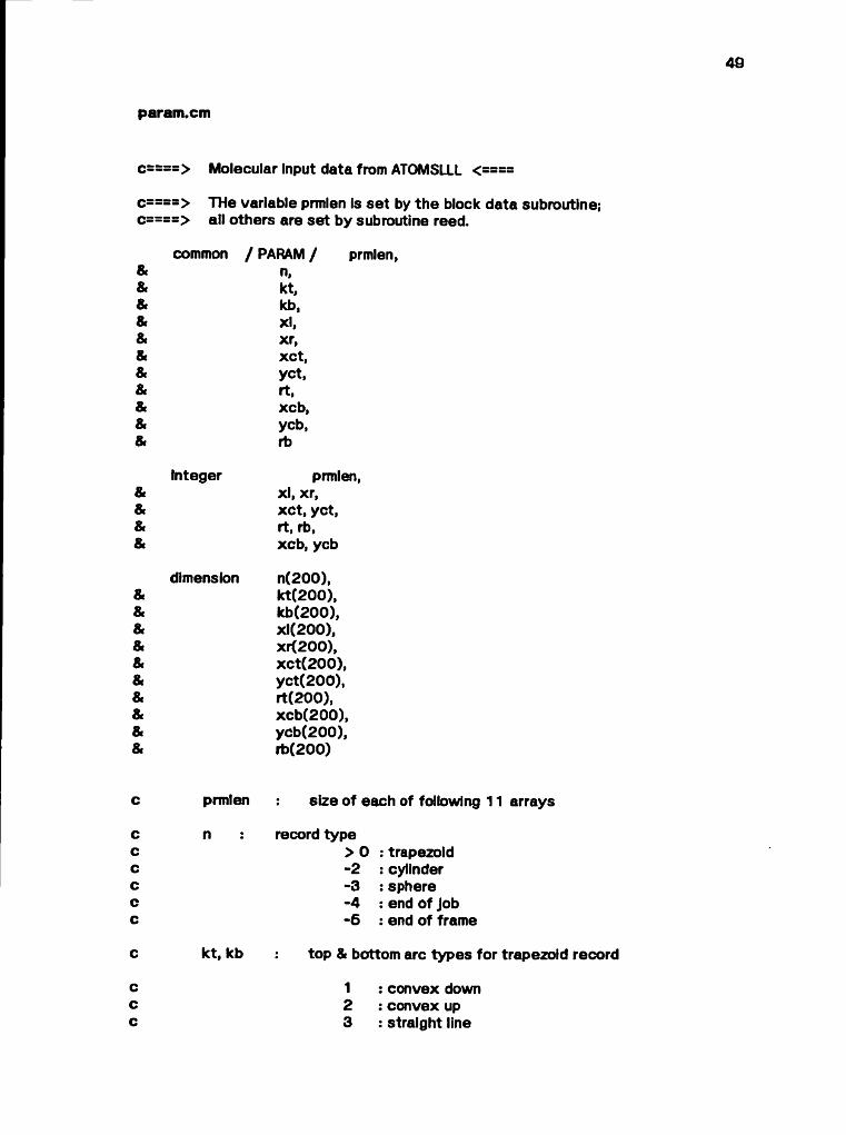
9»param.cm
c====> THe variable prmlen is set by the block data subroutine; c====> all others are set by subroutine reed.
common / PARAM / prmlen, n, kt, kb, xl, xr, xct, yet, rt, xeb, ycb, rb
Integer prmlen,xl, xr, xct, yet, rt, rb, xeb, ycb
dimension n(200), kt(200), kb(200), xl(200), xr(200), xct(200), yct(200), rt(200), xcb(200), ycb(200), rb(200)
c====> Molecular Input data from ATOMSLLL <====
c prmlen size of each of following
c n record typec > 0 : trapezoidc -2 : cylinderc -3 : spherec -4 : end of Jobc -6 : end of frame
c kt, kb top & bottom arc types f
c 1 : convex downc 2 : convex upc 3 : straight line

60
c 4 : special
c top line type & slope for cylinderc colour & x coordinate of centre for sphere.
c xl, xr x coordinates of left & right sides of trapezoidc top line intercept & bottom line type for cylinder,c y coordinate of centre & radius for sphere,c xct, yet, rt : centre & radius of top arc for trapezoid,c bottom line slope & intercept, & middle line typec for cylinder.c xeb, ycb, rb : centre & radius of bottom arc for trapezoid,c middle line slope & intercept, & intermediatec quadratic differencing value for cylinder.

«• a»
8»pgmctl.cm
c====> All variables in this common block are se t by subroutine Init.
c====> Program control variables <====
common / PGMCTL / ifda, iwait, idvice,Ifbslm
c All of the
c ifda :
c iwait:c
c idvicec
c ifbslmccc
following are user specified at run time:
double film advance
generates extra space between completely exposed Dicomed frames so film can be mounted as 35 mm. slides
output device type(Dicomed film recorder / Ikonas frame buffer)
selects actual or simulated frame buffer output When the frame buffer is simulated, output is placed on the file frame_buffer In the current directory; this file can be examined using the Ikonas simulator.

o0 o0 o0 o8 o8 o8 o8
62
qdiff.cm
c<====> Intermediate values used in quadratic differencing calculations <==== c====>c====> The equations from which these values originate are detailed Inc = = => section 4 ofc====>c====> ATOMLLL - A Three-D Opaque Molecule System c====> (Lawrence Livermore Laboratory Version),c====> N. L. Max, UCRL-52646, Jan. 1979. c====>
common / QDIFF / a, ad, bp,c,d,e,f,k3
c a set by routine newcol/
c ad set by routines begcyl & begsph
c bp maximum range for colour exposurec (set by routine newcol)
c c, d, e, f, k3 set by routine begsph

00 «0
radius.cm
c====> Radius parameters <==
common / RADIUS / srt, srb, srr
c srt topc (set by routine trapez, as is srb)
c srb : bottom
c srr squarec (set by routine begsph)
9* fi
* fi»
«•
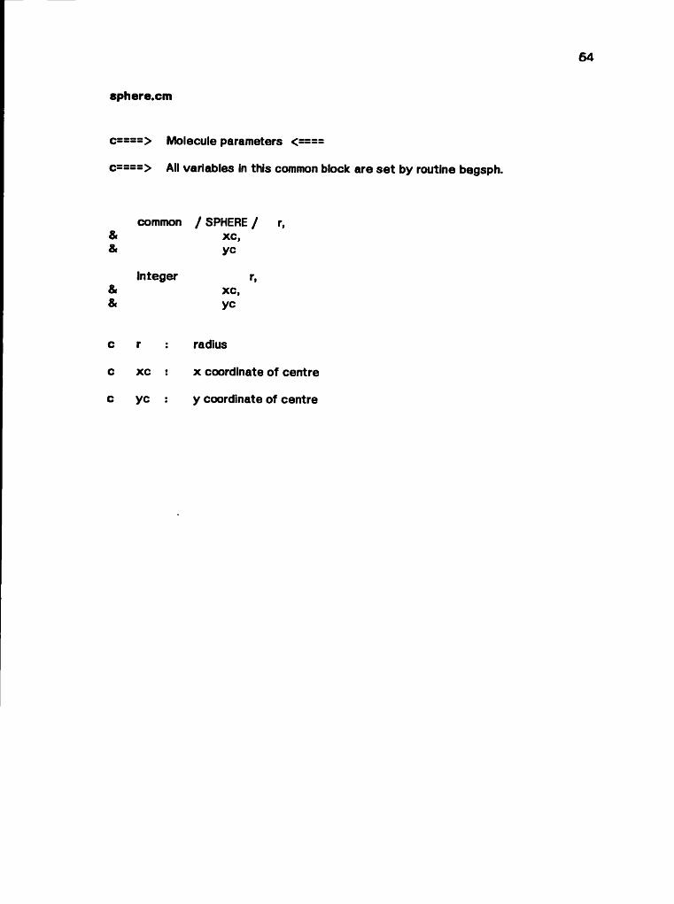
sphere.cm
c====> All variables in this common block are se t by routine begsph.
c====> Molecule parameters <====
common / SPHERE / r, xc, yc
Integer r,xc, yc
c r : radius
c XC ! x coordinate of centre
c yc : y coordinate of centre
65
dni.fCi::: — > MAINLINE <—c::::c:::: This program produces shaded highlighted molecular representations c:::: suitable for output on either a Dicomed film recorder or an Ikonas c:::: frame buffer connected to a DEC PDP/11 computer. It is a structured c:::: FORTRAN 77 extension of the original DicomedTdependent FORTRAN program c:::: obtained from Nelson Max of Lawrence Livermore Laboratory.C::::C:::: References : 1. 'ATOMLLL ATOMS with Shading & Highlights',C:::: N. L. Max, Proceedings of SIGGRAPH 179.C::::c:::: 2. 'ATOMLLL - A Three-D Opaque Molecule Systemc:::: (Lawrence Livermore Laboratory Version)1,c:::: N. L Max, UCRL-52645, Jan. 1979.C:;::c:::: 3. Dicomed Graphic Film Recorder Model D48 -C:::: Operation and Programming Manual.C::::C::::c:::: Input files :C:::: fort.4:C::::C::::C:::: fort.9 :C::::C::::C::::C:::: Output files : c:::: fort.8 :C::::C::::C::::C::::C::::c::::C:::: fort.7 :C::::c:::: user terminal: Execution traceC:::: +c:::: frame buffer statisticsc:::: (if Ikonas is output device)C::::c:::: frameubuffer: screen Image file created for simulated framec:::: buffer output.c:::: May be examined with Ikonas simulator or displayedc:::: directly on the Ikonas.C::::c:::: Program execution is controlled by a self-explanatory input dialogue.C:::sc:::: An efficient quadratic differencing algorithm computes values for c:::: (cos(theta) ** 2) along vertical lines; these are used as indices c:::: Into computed colour lookup tables for shading & object highlighting, c:::: (Details concerning the differencing equations may be found in
measured film densities to compute colour lookup tables for the Dicomed
molecular description file created by the ATOMLLL program, which is a front end for this program.
Dicomed control codes to produce exposed photographic film on a Dicomed film recorder.
N.B. Due to bugs in the FORTRAN 77 compiler and/or quirks of the Unix operating system, this file is always opened In append mode If it already exists.
optional debug output.
8® 8*
fi» fi
» 8» f
i»
c:::: section 4 of Reference 2.)C::::c:::: The program requires 2 passes over the input data for the Dicomed, c:::: which manipulates colour filters one at a time.c:::: Shading & highlighting can be performed simultaneously for the Ikonas, c:::: which requires only a single intensity in RGB format for each pixel to c:::: be illuminated.C:::: Processing Is complete once either an end-of-job indicator or the c:::: physical end of input data has been encountered.
C* • • •c:::: N.B. "Do nothing" code from N. Max's original version c:::: has been commented out.c::::
include 'bond.cm' include 'coitbl.cm' include 'debug.cm' include 'dicntl.cm'Include 'dlco.cm'Include 'tbparm-cm'Include 'ispace.cm' include 'manif.cm' include 'param.cm' include 'pgmctl.cm'
data ¡color / 22 / , ibandw / 21 / ,Ifr / 0 / , newcyl / -2 /, newsph / -3 /, newjob / -4 /, newfrm / -5 /
call initcall output( jnoop, ires )
c====> call setabl( 1 ) call setabl call frmhdr
30 continue idum = 0
o====> call tabout( 3 )6 0 continue
call reed( n, prmlen * 11, ler ) if ( ler .gt. 0 ) go to 30
c====> Colour shading
kstart = 0 80fhHit = 1
c====> call tabout( 1 )call output( jnoop, (color )

nowcol = 0 go to 120
c====> Set shading flag to black & white for highlight calculation
100 ihilit = 2 c====> call tabout( 2 )
call output( Jnoop, Ibandw ) nowcol = 0
c====> The following case statement is performed for each record c====> in every block of input data until either the end-of-job code c====> physical end-of-file Is encountered.
120 do 500 I = kstart + 1, prmlen write(6, 960) I
c====> Continue shading trapezoids in the current atom
if ( n(i) .gt. 0 ) then write(6, 965) call trapez( I, kind )
c====> Begin new frame
else if ( n(i) .eq. newfrm ) then write(6, 980)
if ( ihilit .eq. 1 ) thenIf ( idvice .eq. Idico ) go to 100
elsekstart = icall output( jnoop, ifa )Ifr = If r + 1 write(6, 900) ifr if ( (wait .eq. ion ) then
c====> call tabout( 3 )call output( jflush, jfhish ) read(6, 800) idum
end ifIf ( ifda .eq. ion ) call output( jnoop, ifa ) call frmhdrIf (kstart - prmlen) 80, 60, 50
end If
c====> End of Job
else if ( n(i) .eq. newjob ) then c====> call tabout( 3 )
call output( jflush, jflush ) if ( idvice .eq. ifrbuf ) then
wrlte(6, 910) (minrgb(j), maxrgb(j), j = 1, 7) write(6, 930)write(6, 950) acminx, acmaxx, acminy, acmaxy write(6, 940)

68
write(6, 960) minfbx, maxfbx, minfby, maxfby end if call exit
c====> Begin New Sphere
else If ( n(i) .eq. newsph ) then wiite(6, 970) call begsph( I, kind )
c====> Begin New Cylinder
else if ( n(i) .eq. newcyl) then wiite(6, 976) call begcyl( I, kind )
end if600 continue
If ( ( ihilit .It. 1 ) .or. ( Ihillt .gt. 2 ) ) then write(6, 920) ihilit call exit
elsego to ( 100, 60 ), ihilit
endif
c====> Input formats
800 format( II )
c====> Output formats
900 formate Finished frame', 14)910 format( t20, 'Min Intensity', 5x, 'Max Intensity',
& //'red', t23,16, t41,l6 ,& /'green', t23,16, t41 , 16,& /'yellow', t23,16, t41 , 15,& /'blue', t23,16, t41,16,& /'magenta', t23,16, t41 , 16,& /'cyan', t23,15, t41 , 16,& /'white', t 2 3 , l6 , t 4 1 , i6 )
920 format( //'Main program : ihilit = ', I6,& ' out of range for computed go to' )
930 formate //'Range of calculated pixel addresses )940 formate //'Range of illuminated pixel addresses :' )960 formate t8, 'x : ', 16, ' to ', 16, ' y : ', 16, ' to ', 16 )960 formate 'Record 16 )965 formaté t20, 'Trapezoid' )970 formate t20, 'Sphere' )976 formaté t20, 'Cylinder' )980 formate t20, 'End of frame1 )
end

subroutine begcyl( i, kind )
c:::: This routine is called to initiate processing of a bond (cylinder) C:::: input record.C::::C:::: Input :c:::: I : index of arrays of / PARAM / containing informationc::: relevant to this bond.C::::c:::: Output :c:::: kind : indicates cylindrical trapezoid data requires furtherc:::: processing.C::::c:::: N.B.c:::: 1. Bonds will always be shaded magenta by this program.c::::c:::: 2. This routine was originally part of N. Max's dni.fc:::: mainline module.c::::
Include 'bond.cm' include 'coltbl.cm1 include 'manif.cm1 include 'param.cm1 include 'qdiff.cm'
data magen / 5 /
if ( nowcol .ne. magen ) then call newcol( 5, a, bp )
c====> The following line was missing in N. Max's codec====> (so the program failed for input data containing only bonds)
ad = a / two16 end if
c====> Top values
Jt = kt(l)s t = kb(i) / 32767. markt = 0if ( ( Jt .ne. 1 ) .and. ( abs(st) .le. smin ) ) then
markt = 1 Jt = 3
end if rit = xl(i)
c====> Bottom values
Jb = xKDsb = xct(i) / 32767. markb = 0if ( ( jb .ne. 1 ) .and. ( abs(sb) .le. smin ) ) then
markb = 1 jb = 3
end if rib = yct(i)
==> Middle values
Jm = rt(l)sm = xcb(i) / 32767.if ( ( Jm .ne. 1 ) .and. ( abs(sm) .le. smin ) ) then
markt = 1 markb = 1 Jm = 3
end if rim = ycb(l)
if (jb .gt. 1 .and. jm .gt. 1 .and. sb * sm .It. 0) markb = 1 if (jt .gt. 1 .and. jm .gt. 1 .and. st * sm .It. 0) markt * 1
fm = rb(i) / 32767. fs = 265. * fm * bp c = fs * two 15 kind = kcyl
returnend
61
c:::: This routine Is called to initiate processing of an atom (spherical) c:::: input record.C::::c:::: Input :c:::: I : index into arrays of / PARAM / to information relevantC:::: to this atom.C::::C:::: Output :C:::: kind : indicates spherical trapezoid data for further processingC::::c:::: Some terms used in the quadratic differencing equations are computed.C::::C:::: N.B.c:::: 1. This routine was originally part of N. Max's dni.fc:::: mainline module.
subroutine begsph( i, kind )
include 'coltbl.cm' include 'ispace.cm1 include 'manif.cm' include 'param.cm' include 'qdiff.cm' include 'radius.cm' include 'sphere-cm'
if ( kt(i) .ne. nowcol) then call newcol( kt(l), a, bp ) ad = a / two16
end if
xc = kb(i) yc = xl(i) r = xKOsrr = float(r) ** 2c - bp * 265. * two 15 / srrd s a + c * srre = c * Jsp * 2f - c * jsp * jspk3 = -2 * fkind = ksph
returnend
9° 8*
8° 9®
o 8*
9» 9
° 9*
62
block datac:::: This routine provides initialization of all static constants c:::: in common blocks.C::::
Include 'coltbl.cm* include 'dicntl.cm' include 'dico.cm' Include 'fbparm.cm' include 'ispace.cm1 include 'manif.cm' include 'param.cm'
AIIIIIIllo
/ COLTBL /
dataapp / 14*.01 / ,
& bpp / 6 * 0.99, 0.45,
AIIIIIIIIo
/ DICNTL /
data icomp / z '88a9' / ,& if a / z 'dO O ' / ,& ifepl / z '20001 / ,& Ifep2 / z '7000' / ,& Ifesl / z '2000' / ,& ifes2 / z '3000' / ,& Ifp / z' 1000' / ,& ipes / z'aOOO' / ,& ipos / z '4000' / ,& ires / z '90001 /
AII¡IIIO
/ DICO /
databp tr / 1 / ,& bufmax / 200 /
o n ii ii ii V / FBPARM /
* 0.99 /
data nextx nexty minrgb
- maxrgb shdctl
/ 0 / ,/ o /,/ 7 * 9999 /, / 7 * -9999 /,m
'===> / MAN IF /
dataidlco/ 1 /,Ifrbuf / 2 / ,ihoriz / 1 / ,loerr / 2 / , loft / 0 / ,
63
& Ion / 1 / ,& !2to14 / 1 6 3 8 4 /,& Jnoop / 1 / ,& jsavex / 2 / ,& jsavey / 3 / ,& jpacki / 4 / ,& Junpki / 5 / ,& Jemiti / 6 / ,& jflush / 7 / ,& key! / 2 / ,& ksph/ 1 / ,& rmaxi / 32767.0 / ,& r2to14 / 1 6 3 8 4 .0 /,& smln / 0.1 / ,& two16 / 4 1 9 4 3 0 4 .0 /
c====> / PARAM /
data prmlen / 200 /end

subroutine djcemp
This routine flushes the current contents of the Dicomed output buffer to the file 'fo rt.81 in the current directory.
include 'dico.cm'
if ( bptr .ne. 1 ) then limit = bptr - 1w rite( 8 ) ( buff(i), i = 1, limit) bptr = 1
endifreturnend
65
c:::: This routine adds another 16-b it word to the Dicomed outputc:::: buffer, firs t emptying the buffer if it is already full.
• • • v< • • •c:::: Input :c:::: iword : 32-b it integer to be added to bufferAt • ♦ •W« • • •
subroutine dicowd( (word )
Include 'dico.cm'
If ( bptr .gt. bufmax ) then w rite (8 ) buff bptr = 1
end If
buff (bptr) = iword bptr = bptr + 1 return end
o o
66
subroutine exit
C: This routine closes all files associated with the program before terminating execution.
Include 'manif.cm' include 'pgmctl.cm'
c====> Close input files
close ( 4 ) close ( 6 ) close ( 9 )
c====> Close output files
w rite( 6 , 9 0 0 )9 0 0 format ( 1 End of jo b ...' )
close ( 6 )if ( idvice .eq. ifrbuf ) then
call Fclofbelse
close ( 8 ) end if
stopend
67
c:::: This routine emits the Dicomed control sequence for a frame header.c::::c:::: MB. This code was originally part of M Max's mainline module dni.fC::::c:::: Reference :c:::: Dicomed Graphic Rim Recorder Model D48 -c:::: Operation & Programming Manual.C* * • •
subroutine frmhdr
include 'dicntl.cm' include 'manif.cm*
c Resetcall output( jnoop, ires )
c ECS - select raster modecall output( jnoop, 1 6 )
c ECS - colour exposurecall output( jnoop, 1 8 )
c ICS with optionscall output( Jnoop, fcomp )
c ECS - colour translationcall output( jnoop, 2 2 )
c PES - set horizontal spacingcall output( jnoop, ipesl )
c PES - set vertical spacingcall output( jnoop, Ipes2 )
c PES - set background exposure code &c no. of points/element in both directions
call output( jnoop, ipes3 ) return end

0$ O «C 0®
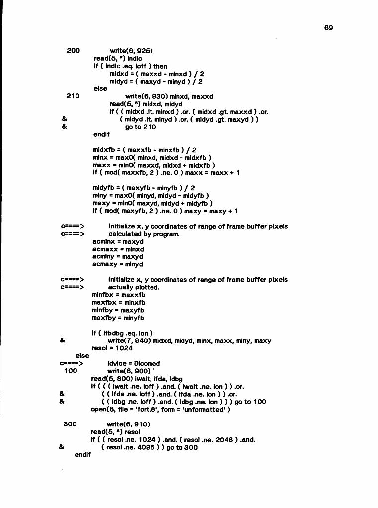
subroutine init
C:::: This routine :c:::: 1. queries the user for program control parametersc:::: 2 . computes, if necessary, pixel coordinate boundaries of thec:::: frame buffer visible window.c:::: 3 . computes spacing constants dependent on the output devicec:::: resolution.C::::c:::: N.B. This code was originally part of N. Max's mainline module dni.f.C::::
include 'debug.cm' include 'dicntl.cm' include 'fbparm.cm' include 'ispace.cm' include 'manif.cm' include 'pgmctl.cm'
integer resol
c Dicomed boundariesdata minxd, minyd / 1, 1 / ,
maxxd, maxyd / 1024 , 1024 / , Ikonas boundaries
minxfb, minyfb / 0, 0 / , m axxfb, maxyfb / 5 11 , 511 /
c====> Obtain run parameters from user
1 2 5 w r ite (6 ,9 0 5 ) read(5, * ) idviceif ( ( idvice .ne. Idico ) .and. ( idvice .ne. ifrbuf ) ) go to 1 2 6
if ( idvice .eq. ifrbuf ) then
1 3 5 w r ite (6 ,9 5 0 )read(5, * ) shdctlif ( ( shdctl .ne. ioff ) .and. ( shdctl .ne. Ion ) ) go to 136
1 5 0 w r ite (6 ,9 1 5 )read(5, * ) ifbsimIf ( ( ifbsim .ne. ioff ) .and. ( ifbsim .ne. Ion ) ) go to 150
1 7 5 w rite(6 , 9 2 0 )read(5, * ) ifbdbgIf ( ( ifbdbg .ne. ioff ) .and. ( ifbdbg .ne. ion ) ) go to 1 7 5
call Finifb( ioff, ifbsim )
c==-=====> Compute a visible frame buffer window centred about the c========> specified raster position of the Dicomed screen
9» 99
200
210
c====>c====>
c====>c====>
&
elsec====>
100
&&
3 0 0
&
w rite(6, 9 2 5 ) re a d (6 ,* ) indie if ( indie .eq. loff ) then
midxd = ( maxxd - minxd ) / 2 mldyd = ( maxyd - minyd ) / 2
elsew rite(6, 9 3 0 ) minxd, maxxd
read(6, * ) midxd, midydif ( ( midxd .It. minxd ) .or. ( midxd .gt. maxxd ) .or.
( midyd .It. minyd ) .or. ( mldyd .gt. maxyd ) ) go to 2 1 0
endif
midxfb = ( maxxfb - minxfb ) / 2minx = max0( minxd, midxd - midxfb )m axx = mln0( maxxd, midxd + midxfb )if ( mod( maxxfb, 2 ) .ne. 0 ) maxx = maxx + 1
midyfb = ( maxyfb - minyfb ) / 2 miny = max0( minyd, midyd - midyfb ) maxy = mln0( maxyd, midyd + midyfb )If ( mod( maxyfb, 2 ) .ne. 0 ) maxy = maxy + 1
Initialize x , y coordinates o f range of frame buffer pixels calculated by program,
acminx = maxyd acm axx = minxd acminy = maxyd acmaxy = minyd
Initialize x, y coordinates of range of frame buffer pixels actually plotted,
mlnfbx = maxxfb m axfbx = minxfb minfby = maxyfb m axfby = minyfb
If ( ifbdbg .eq. ion )w rlte(7, 9 4 0 ) midxd, midyd, minx, maxx, miny, maxy
resol = 1 02 4
idvlce = Dicomed wrtte(6, 9 0 0 ) ‘
read(5, 8 0 0 ) iwait, tfda, idbg If ( ( ( iwait .ne. ioff ) .and. ( iwait .ne. ion ) ) .or.
( ( ifda .ne. loff ) .and. ( ifda .ne. Ion ) ) .or.( ( idbg .ne. loff ) .and. ( idbg .ne. Ion ) ) ) go to 100
open(8, file = 'fort.8 ', form = 'unformatted' )
w rite(6, 9 1 0 ) read(5, * ) resolif ( ( resol .ne. 1 0 2 4 ) .and. ( resol .ne. 2 0 4 8 ) .and.
( resol .ne. 4 0 9 6 ) ) go to 3 0 0endif

9» 8
» _
8»
9»
70
c====> Calculate constants derived from resolution
c====> / ISPACE /isp = 4 0 9 6 / resol isp2 = isp / 2 jsp = 8 * isp Jsp2 = 8 * Isp2 f jsp = float( jsp ) fjs p 2 = float( Jsp2 ) tjsp = 2. * f jsp tjsq = 2. * f jsp * fjsp
c====> / DICNTL /ipesl = ipes + 612 * Isp + 8 Ipes2 = 512 * isp + 8 Ipes3 = isp " 17
return
c====> Input formats
8 0 0 format( 3i1 )
c====> Output formats
9 0 0 formate / ' Wait between frames, double film advance, debug trace:',& / ' eO:no, 1 :yes) 3i1 form at:1 )
9 0 6 formate / ' Target output device:',& / ' ei:0icomed, 2:lkonas) free format: ' )
9 1 0 formate / ' Resolution : 1024, 2 0 4 8 , 4 0 9 6 : free format: ' )9 1 5 formate / ' Type of frame buffer:',
& / ' eO:actual, 1 simulated) free format: ' )9 2 0 formate / ' Frame buffer debug output desired?1,
& / ' eO:no, 1 :yes) free format: ' )9 2 5 formate / ' By default, centre portion of ATOMLLL data will be displayed ',
' on frame buffer.', / ' Do you wish to change area displayed?',/ ’ eO:no, 1 :yes) free format: ' )formate / ' x, y coordinates (in Dicomed raster units) o f centre of area ', 'to be displayed : free format:',/ ' (M ust be in range ', I7, ' to ', i7 ') ' )
9 4 0 formate / ' Init : midxd, midyd = ', 2 i8 , ' minx, maxx = ', 2 i8 ,& ' mlny, maxy = ', 2 i8 )
9 5 0 formate / ' Compute highlights?1, / ' (0:no, 1 :yes) free format: ' )
end
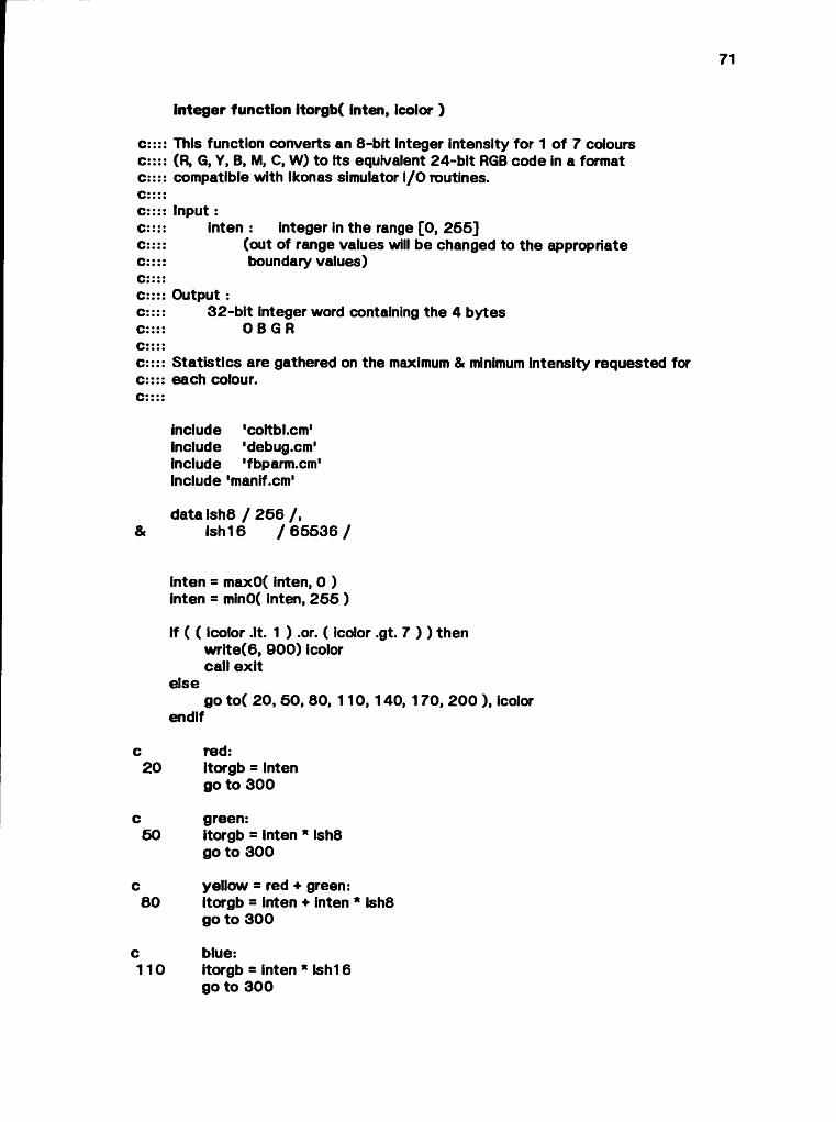
in teger function itorgb( inten, ¡color )
c:::: This function converts an 8-b it integer intensity for 1 o f 7 colours c:::: (R, G, Y, B, M, C, W) to its equivalent 2 4 -b it RGB code in a format c:::: compatible with Ikonas simulator I/O routines.C::::C:::: Input :c:::: inten : integer in the range [0 , 2 5 5 ]c:::: (out of range values will be changed to the appropriatec: : : : boundary values)C::::C:::: Output :c:::: 3 2 -b it integer word containing the 4 bytesC:::: 0 B G Rc::::c:::: S tatistics are gathered on the maximum & minimum intensity requested for c:::: each colour.C::::
include 'coltbl.cm' include 'debug.cm' include 'fbparm.cm' Include 'manif.cm'
data Ish8 / 2 6 6 / ,& Ish16 / 6 5 5 3 6 /
inten = maxO( inten, 0 ) inten = minO( inten, 2 5 5 )
If ( ( icolor .lt. 1 ) .or. ( icolor .gt. 7 ) ) then w rite (6 , 9 0 0 ) icolor call e x it
eisego to ( 20 , 5 0 , 80, 110 , 140, 170 , 2 0 0 ), icolor
endif
c red:2 0 itorgb = Inten
go to 3 0 0
c green:5 0 itorgb = inten * Ish8
go to 3 0 0
c yellow = red + green:8 0 itorgb = inten + inten * Ish8
go to 3 0 0
c blue:1 1 0 itorgb = inten * Ish16
go to 3 0 0

c magenta = red + blue:1 4 0 itorgb = inten + inten * Ish16
go to 3 0 0
c cyan = green + blue:1 7 0 Itorgb = Inten * Ish8 + inten * Ish16
go to 3 0 0
c w hite = red + green + blue:2 0 0 itorgb = inten + inten * Ish8 + inten * Ish16
300minrgb(icolor) = min0( inten, minrgb(icolor) ) maxrgb(icolor) = max0( inten, maxrgb(icolor) )
c====> Output formats
6 0 0 format( 'itorgb : icolor = ¡5 ,1 out of range for computed go to* )
returnend
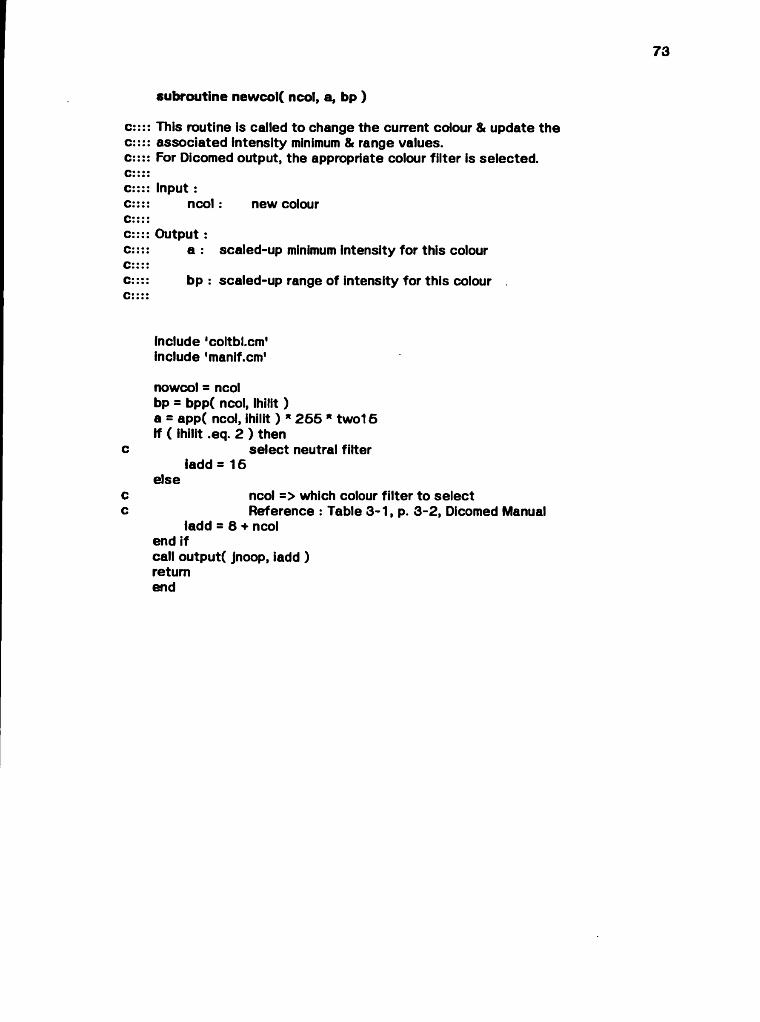
73
c:::: This routine is called to change the current colour & update thec:::: associated intensity minimum & range values.c:::: For Dicomed output, the appropriate colour filter is selected.c::::c:::: Input :c:::: ncol : new colourC::::c:::: Output :c:::: a : scaled-up minimum intensity for this colourC::::c:::: bp : scaled-up range of intensity for this colour .c::::
subroutine newcol( ncol, a, bp )
include 'coltbLcm' include 'manif.cm'
nowcol = ncol bp = bpp( ncol, Ihilit ) a = app( ncol, ihilit ) * 2 5 5 * two15 if ( ihilit .eq. 2 ) then
c select neutral filteriadd = 15
elsec ncol => which colour filter to selectc Reference : Table 3 -1 , p. 3 -2 , Dicomed Manual
iadd = 8 + ncol end ifcall output( jnoop, iadd )returnend

8» fi»
c:::: This routine channels output according to the user-selected display c:::: device. It replaces all calls to dicowd & dicemp in the original version; c:::: hence it is assumed that such calls are made in the correct order c:::: for controlling the Dicomed.c::::C:::: Input :c:::: ic n t l: Describes the interpretation of the parameter iword.c:::: It can be 1 of the following, defined in / MANIF / :C:::: JnoopC:::: jsavexc:::: jsaveyC:::: jpackiC:::: junpkiC:::: jemitiC:::: Jflushc::::c:::: iword : 32 -b it integer destined for output deviceC::::c:::: When the Ikonas frame buffer has been selected as the output device :C::::c:::: 1. x , y coordinates must be rescaled down from the range (1 , 4 0 9 6 )c:::: to (1 ,1 0 2 4 ), as the Dicomed permits illumination ofc:::: n by m rectangular 'meta-pixels' when used a t less thanc:::: its maximum resolution of 4 09 6 .c::::c:::: 2. Only pixels within the frame buffer visible window will bec:::: displayed.C::::c:::: 3 . Pixels are processed along horizontal scanlines.C::::c:::: 4. When highlighting, white is added individually toc:::: each of the 3 colour components (R, G, B) previously storedc:::: in that pixel, to avoid overflow of any colour component intoc:::: adjacent one(s).C::::
subroutine output( icntl, iword )
include 'coltbl.cm'Include 'debug.cm'include 'fbparm.cm'include 'Ispace.cm'include 'manif.cm'include 'pgmctl.cm'
logical vlsibx,& visiby
integer and, ecmask, itorgb
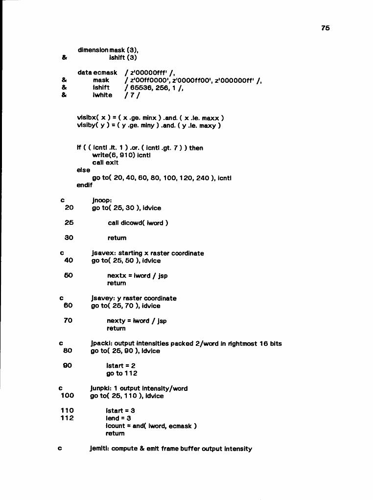
«6 «S «ò
&dimension mask (3 ),
ishift (3 )
c20
2 5
3 0
c4 0
6 0
c6 0
70
c8 0
9 0
c100
110112
data ecmask mask ishift Iwhite
/ z'OOOOOfff' / ,/ z'OOffOOOO', z'OOOOffOO', z'OOOOOOff ' / , / 6 5 5 3 6 , 256 , 1 / ,m
visibx( x ) = ( x .ge. minx ) .and. ( x .le. maxx ) visiby( y ) = ( y .ge. miny ) .and. ( y .le. maxy )
If ( ( icntl .It. 1 ) .or. ( icntl .gt. 7 ) ) then w rite (6 , 9 1 0 ) icntl call ex it
elsego to ( 20, 40 , 60, 80, 1 0 0 ,1 2 0 , 2 4 0 ), icntl
endif
jnoop:go to ( 25 , 3 0 ), idvice
call dicowd( iword )
return
jsavex: starting x raster coordinate go to ( 25 , 5 0 ), idvice
nextx = iword / jsp return
jsavey: y raster coordinate go to ( 25 , 70 ), idvice
nexty = iword / jsp return
Jpacki: output intensities packed 2 /w ord in rightmost 16 bits go to ( 25 , 9 0 ), idvice
(start = 2 go to 1 12
Junpki: 1 output intensity/word go to ( 2 5 ,1 1 0 ) , idvice
(start = 3 lend = 3Icount = and( iword, ecmask ) return
c Jemlti: compute & emit frame buffer output intensity
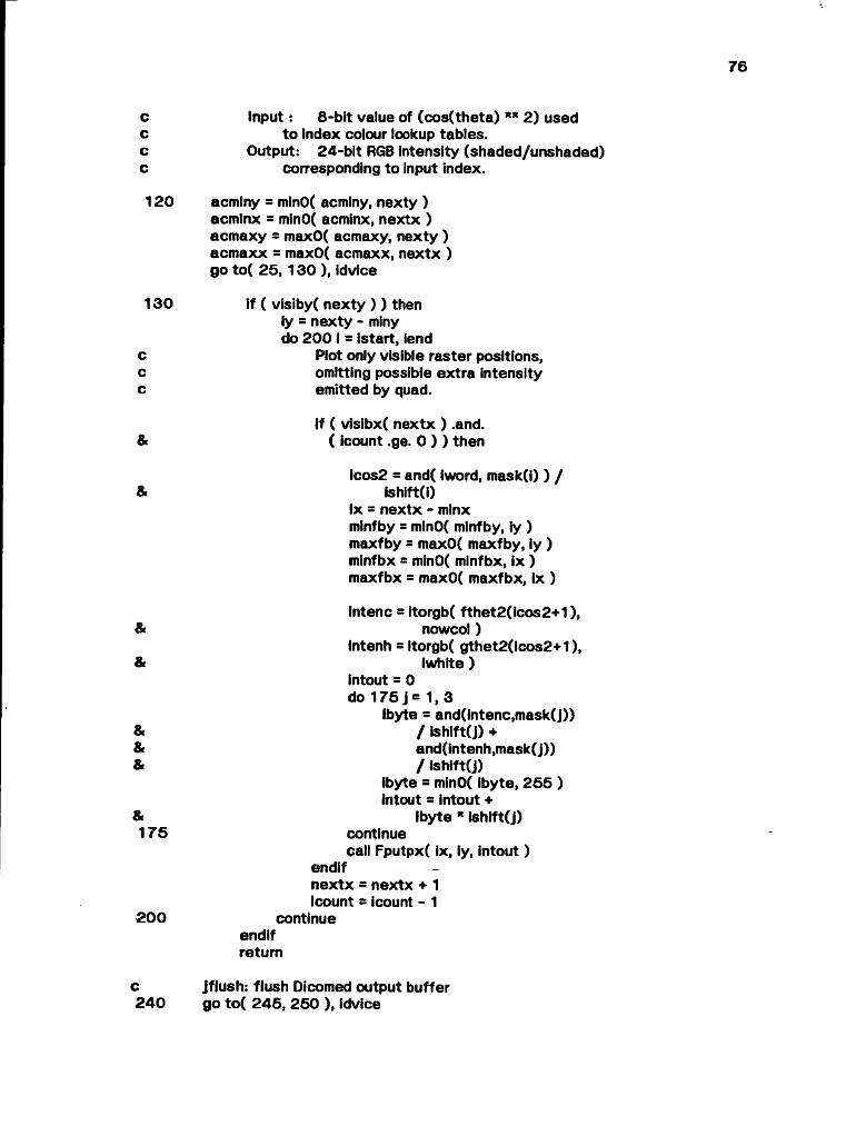
8» 8
« 9»
Cccc
120
130
ccc
&
&
&
&
&1 7 5
200
In p u t: 8 -b it value of (cos(theta) * * 2 ) usedto index colour lookup tables.
Output: 2 4 -b it RGB intensity (shaded/unshaded) corresponding to input index.
acminy = minO( acminy, nexty ) acmlnx = minO( acminx, nextx ) acm axy = maxO( acmaxy, nexty ) acm axx = maxO( acmaxx, nextx ) go to ( 2 5 ,1 3 0 ), idvlce
If ( visiby( nexty ) ) then ly = nexty - miny do 2 0 0 i = Istart, lend
Plot only visible raster positions, omitting possible extra intensity emitted by quad.
if ( visibx( nextx ) .and.( icount .ge. 0 ) ) then
icos2 = and( iword, mask(i) ) / Ishift(i)
lx = nextx - minx minfby = mlnO( minfby, iy ) maxfby = maxO( maxfby, iy ) minfbx = minO( minfbx, ix ) maxfbx = maxO( maxfbx, ix )
intenc = itorgb( fthet2(icos2+1), nowcol)
Intenh = ftorgb( gthet2(icos2+1), Iwhite )
intout = 0 do 175 j= 1, 3
ibyte = and(intenc,mask(j))/ Ishlft(J) + and(intenh,mask(j))/ ishift(J)
ibyte = minO( ibyte, 2 5 5 ) intout = intout +
Ibyte * ishift(J)continuecall Fputpx( ix, iy, intout )
endifnextx = nextx + 1 Icount = icount - 1
continueendifreturn
c2 4 0
jflush: flush Dicomed output buffer go to ( 2 4 5 , 2 5 0 ), idvice
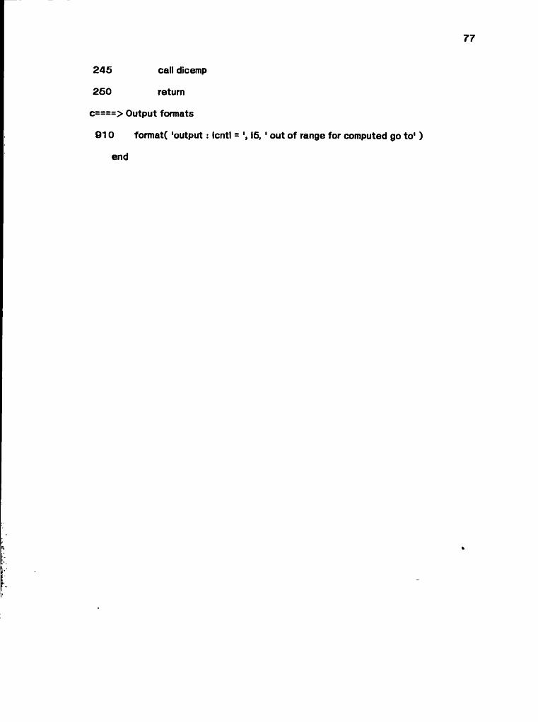
77
2 4 5 call dicemp
2 6 0 return
c====> Output formats
9 1 0 format( 'output : Icntl = IS, 1 out of range for computed go to 1 )
end
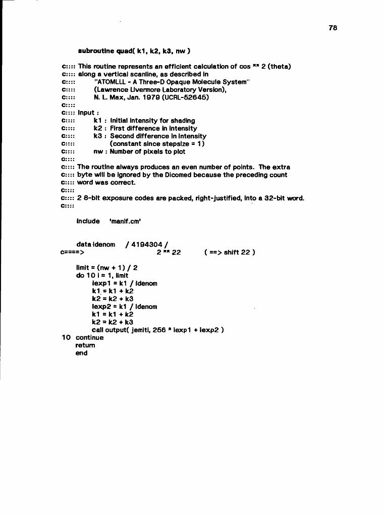
o n
subroutine quad( k1, k2, k3, nw )
C:C:C:C:C:C:C:C:C:C:c:C:c:C:C:C:C:
This routine represents an efficient calculation of cos ”* 2 (theta ) along a vertical scanline, as described in
"ATOMLLL - A Three-D Opaque Molecule System"(Lawrence Livermore Laboratory Version),N. L Max, Jan. 1 979 (UCRL-52646)
Input :k1 : Initial intensity for shading k2 : First difference in intensity k3 : Second difference in intensity
(constant since stepsize = 1) nw : Number of pixels to plot
The routine always produces an even number of points. The extra byte will be ignored by the Dicomed because the preceding count word was correct.
2 8 -b it exposure codes are packed, right-justified, into a 3 2 -b it word.
include 'manlf.cm'
data idenom / 4 1 9 4 3 0 4 /c====> 2 * * 2 2 ( ==> shift 2 2 )
limit = (nw + 1 ) / 2 do 10 i = 1, limit
ie x p l = k1 / Idenom k1 = k1 + k2 k2 = k2 + k3 Iexp2 = k1 / idenom k1 = k1 + k2 k2 = k2 + k3call output( jemiti, 2 5 6 * iexp l + Iexp2 )
10 continue return end
subroutine reed ( n, len, ier )
c:::: This routine reads a block of data produced by the ATOMLLL program Into c:::: the 11 consecutive arrays of / PARAM / .C::::C:::: In p u t:c:::: n : Starting address of the 1st o f the 11 arrays in / PARAM /c::::c:::: len : no. o f words of input data to readC ::::c:::: ier : error indicator:c:::: < 0 :end-of-fileC:::: = 0 : a l ! i s w e l lc:::: > 0 terror occurred during readC::::
include 'manif.cm'
integer n(len)
open( 9 , file = 'fort.9' ) rewind( 9 )read( 9 , 100 , iostat = ier ) n
1 0 0 formati 1 0 i7 )
3 0 0 return end
subroutine setabl
c:::: When th e output device is the Dicomed film recorder:c:::: This routine computes & emits Dicomed colour translation tablesc:::: which compensate for nonlinearities on the output device & film.
c:::: It uses the file 'fo rt.41, containing a table of measured filmc:::: densities stored as -log base 10(intensity)c:::: i.e., the fraction of light transmitted by the film.c:::: These densities decrease as output intensity level increases.C:::: The format of this file is as follows:c:::: 3 2 rows representing intensity levels, each containing:c:::: film densities for all 7 colour filters at this levelc:::: a single value to trigger debug output (if > 8 0 0 0 )
c:::: A table o f 2 5 6 exposure codes per colour is computed as follows: c:::: 1. measured intensity I is obtained from corresponding measuredc:::: d e n s ity :c:::: 1 = 1 0 * * (-den / 100)c:::: 2 . Desired output intensities are interpolated from measuredc:::: Intensities, using the equationsc:::: F(theta) = .1 + .9 * ((cos(th eta )) * * 2 ) **.61C:::: for colourc:::: G (theta) = .8 * F + .39 * ( .8 *((co s (th e ta )) ** 2 ) * * 14 +c:::: .2 * ((cos(theta)) * * 2 ) ** ( 1 4 /4 ) )c:::: for highlights,c:::: suitably scaled to produce values within the range of measuredc:::: intensities obtained from the input film densities.c:::: These equations are approximately equivalent to Lambert's Lawc:::: for the representation of diffuse and specular reflection:c:::: i.e., f(th e ta ) = A + D cos(theta)c:::: g (theta) = C (cos(theta)) * * n, n large.c:::: except:C:::: 1. they are In terms of cos**2 rather than cosc:::: 2 . G has extra terms to eliminate Mach band e ffec tsC::::c:::: The 8 sub-tables are calculated & emitted In the orderc:::: black & white, red, green, yellow, blue, magenta, cyan, neutral.c:::: [Black & white calculations use film densities for neutral (w hite).]C::::c:::: The Dicomed saves these lookup tables; each emitted illumination c:::: level from the quadratic differencing computation is actually a c:::: cos**2 treated as an index into the appropriate colour lookup table, c:::: Then, according to options previously selected, the film is exposed c:::: proportional to -k>g(base 1 0 ) of the indexed table value.C ::::c:::: When th e output device is the Ikonas:c:::: The task is simplified, as the file of film densities can bec:::: ignored. It is necessary only to compute & save the tables for F & G,c:::: scaled to the range 0 -2 5 5 (assuming we wish to allow the full rangec:::: of intensities for each colour).c:::: G = 0 if no shading is desired.C ::::c:::: N.B. "Do nothing" code from N. Max's original program has been
go
go
go
pg
op
g»
go
o
g
ogo
61
c:::: commented out, and the input parameter removed.C::::
include 'coltbl.cm' include 'debug.cm' include 'fbparm.cm' include 'manif.cm' include 'pgmctl.cm'
dimension iden(32, 7), z i(32 ), jcode(32)
dimension itb l(2 0 48 ) equivalence ( zimax, z i(32 ) ),
( zimin, z i(1 ) )
d a ta b l / . 1 0 / ,C1 / -00 / ,e1 / 61 / ,b2 / -08 / ,c2 / .39 / ,e2 / 1 4 . / ,fbmin / 0 .0 / ,fbm ax / 2 56 .0 /
data ifs1 / z '2 0 0 0 ' / ,& Ifs2 / z'dOOO1 /
c Ifs1 FES (Deferred status; p. 3.8 in Dicomed manual)c tfs2 F6 - load translation table & ES - read from Inputc until element count satisfied, (p. 3 -1 4 , 3 -3 4 )
c Options selected:c 8 -b it exposure codesc exposure on film increases as input exposure codec increases.c ............... proportional to Inverse log of exposurec code.
c====> da ta isub / 1 /
c====> * * Modification **c====> Film densities read for all data types - atoms, bonds, orc====> a mixture of both; previously not done for bonds.c====>if ( kind .eq. ksph ) then
if ( idvlce .eq. idico ) then open (4 , file='fort.4l) rewind (4 ) do 1 0 i = 1 ,3 2

4 4
10read (4 , 8 0 0 ) jcode(i), ( iden(l, J), j = 1 ,7 )
continue
A A A A A A II
II II
II II
n II
II II
II II
ii ■I
II ll
II II
II II
ll ll
ll ll
llo o o o o u
read (4 , 8 0 0 ) idum else
if ( kind .na k c y l) then write (6 , 9 0 0 ) return
endifendif
call output( jnoop, ifs1 )
c====> 2 0 4 8 (= 8 * 2 5 6 ) is element countc====> l.e., the number of entries In the table,
call output( jnoop, ifs2 + 2 0 4 8 )
do 5 0 0 m = 1, 8
AllllIIllu i f ( m .eq. 1 ) thenUse neutral filter values
J = 7else
j = m - 1endif
AiillllllO
Obtain measured intensities from measured film densities
3 0
do 3 0 i = 1 ,3 2zi(i) = 10.0 * * ( float( - iden(i, j ) ) / 100 . )
continuezs = zlmax - zimin do 4 0 0 k = 0, 2 5 5
cos2th = float( k ) / 255 .
n ii ii ii ii V Compute des, the desired intensity
o o
o o
ii ii
ii ii
n ii
ii it
n ii
ii ii
n ii
ii ii
V V
V V if ( kind .eq. kcyl ) then
des = zimin + cos2th * zselse
kind .eq. ksphd1 = b1 + c l * cos2th ** e1 If ( m .eq. 1 ) then
c====>
&&
Compute black & white table values d2 = b2 * d1 + c2 *
(.8 * cos2th ** e2 +.2 * cos2th ** ( e2 / 4. ))
des = zimin + zs * d2else
des = zimin + zs * d1
o II II II II V Compute colour valuesendif
c endif
o II II II II V Now find an intensity .gt. des do 80 I = 2 , 32
«0 «8
83
8 0
70
Wl s zi(l)If ( wl - des ) 80, 7 0 , 9 0 mnt = jcode(l) * 16 go to 110
continue
c====> Interpolate exposure index from nearest measured Intensity9 0 f jc = float( jcode(l) )
fjc1 = float( jcode(l - 1) ) wl1 = zi(l - 1) if ( k .eq. 0 ) then
mnt = 0else
c====> If ( ( m .eq. 1 ) .and. ( kind .eq. kcyl ) ) thenc====> mnt = 4 * kc====> else
mnt = ifix ( ( ( des - wl1 ) * ( f jc - fJc1 ) /& ( w l-w l1 ) + fjc1 ) * 16. + . 5 )c====> endif
endifc====> mnt is exposure code
1 1 0 call output( Jnoop, mnt )c====> itbl(isub) = mnt c====> Isub = isub + 1
if ( idbg .eq. 6 )& write( 7, * ) mnt
if ( idum .ge. 8 0 0 0 + m )& write (7 , 9 1 0 ) m, k, I, mnt, des
4 0 0 continue6 0 0 continue
call output( jflush, jflush ) c====> w rlte( 1, 9 9 9 ) itbl
elsec====> Output device Is frame buffer
do 6 0 0 k = 1 ,2 6 6cos2th = float(k - 1) / 255 .fbscal = fbmax - fbmtnd1 = b1 + c1 * cos2th ** e1fth e t2 (k ) = ifix ( d1 * fbscal + fbmin + 0 .6 )if ( shdctl .eq. ion ) then
gthet2(k) = ifix( ( b2 * d1 + c2 *(0 .8 * cos2th * * e2 + 0 .2 * cos2th **(e 2 /4 . ) ) ) * fbscal + fbmin + 0 .5 )
elsegthet2 (k ) = 0
end If6 0 0 continue
if ( ifbdbg .eq. ion ) w rite(7, 9 9 9 ) fth e t2 , gthet2 end if return
c====> Input formats
8 0 0 format ( 8 i5 )
c==3=> Output formats
9 0 0 format ( 1 Error in s e ta b l: input parameter is not sphere1, & 1 or cylinder1 )
9 1 0
9 9 9 end
format ( 4i6, f 11 .4 )
format( 2 5 ( 1018/ ), 618, / / / )
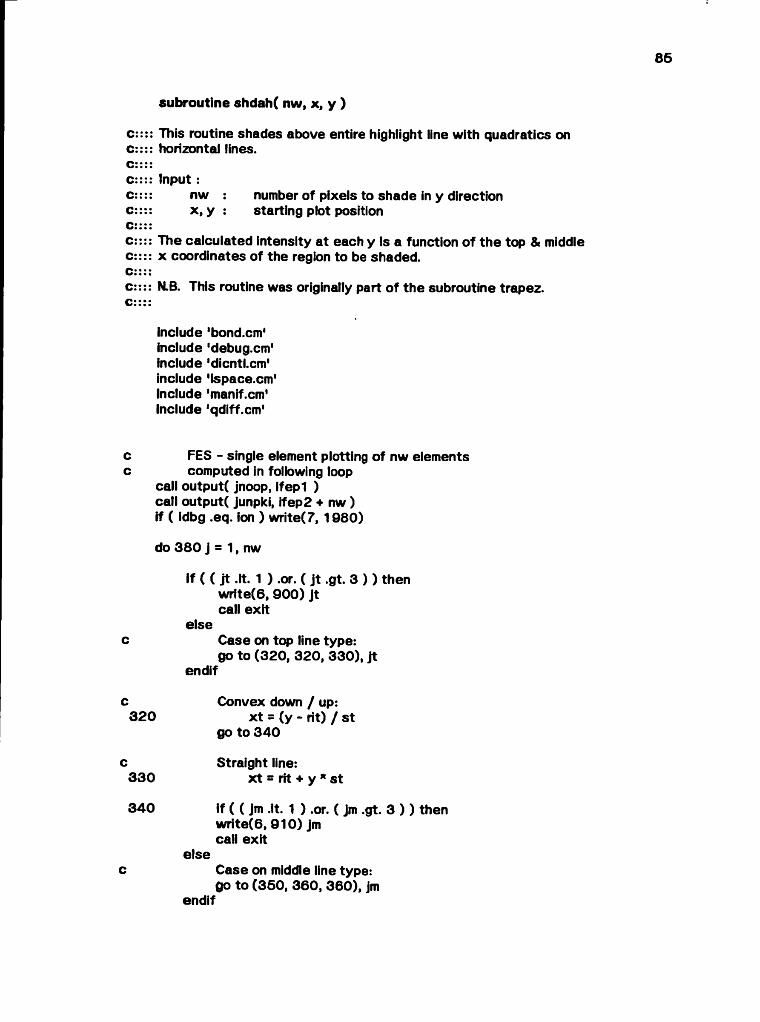
subroutine shdah( nw, x, y )
c:::: This routine shades above entire highlight line with quadratics on C:::: horizontal lines.C::::C:::: Input :c:::: nw : number of pixels to shade in y directionc:::: x , y : starting plot positionC::::c:::: The calculated intensity at each y is a function o f the top & middle c:::: x coordinates of the region to be shaded.C::::c:::: N.B. This routine was originally part of the subroutine trapez. c::::
Include 'bond.cm' include 'debug.cm' include 'dicntLcm' include 'ispace.cm' Include 'manif.cm' Include 'qdiff.cm'
c FES - single element plotting of nw elementsc computed in following loop
call output( jnoop, ifep l ) call output( junpki, ifep2 + nw ) if ( idbg .eq. ion ) write(7, 1 9 8 0 )
do 3 8 0 j = 1, nw
if ( ( j t .It. 1 ) .or. ( j t .gt. 3 ) ) then wrfte(6, 9 0 0 ) j t call exit
elsec Case on top line type:
go to (3 2 0 , 3 20 , 3 3 0 ), j tendif
c Convex down / up:3 2 0 x t = (y - Ht) / st
go to 3 4 0
c Straight line:3 3 0 x t = lit + y * st
3 4 0 if ( ( jm .It. 1 ) .or. ( Jm .gt. 3 ) ) thenw rite(6, 9 1 0 ) jm call exit
elsec Case on middle line type:
go to (3 5 0 , 3 60 , 3 6 0 ), jmendif

66
c Convex down:3 5 0 xm = (y - rim) / sm
go to 3 7 0
c Convex up / staight line:3 6 0 xm = rim + y * sm
3 7 0 id = fs * (1 . - ( (x - x m )/(x t - xm )) ** 2 ) + adid = min0( 2 55 , max0( 0, id ) )
c====> Plot 1 element in horizontal direction at exposurec====> level id
call output( jemiti, ifp + id ) if ( idbg .eq. 2 ) w rite(7, 1990 ) y = y + f jsp
3 8 0 continue return
c====> Output formats
9 0 0 format( 'shdah: Jt = I 6 , 1 out of range for computed go to* )9 1 0 format( 'shdah: jm = I5, 1 out of range for computed go to ' )
1 9 8 0 formate 'trapez #9' )1 9 9 0 formate 'trapez #1 O' )
end
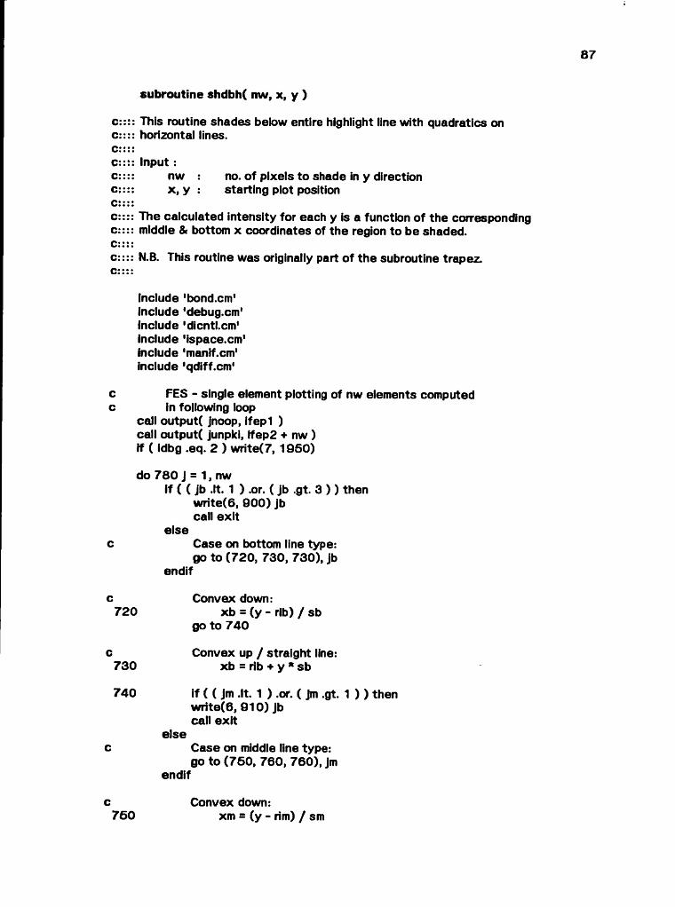
c:::: This routine shades below entire highlight line with quadratics on c:::: horizontal lines.c::::C:::: Input :c:::: nw no. of pixels to shade in y directionc:::: x , y : starting plot positionc::::c:::: The calculated intensity for each y is a function of the corresponding c:::: middle & bottom x coordinates of the region to be shaded.C::::c:::: N.B. This routine was originally part of the subroutine trapez.c::::
subroutine shdbh( nw, x, y )
include 'bond.cm' include 'debug.cm' include 'dicntl.cm' include 'ispace.cm' include 'manif.cm' include 'qdiff.cm'
c FES - single element plotting of nw elements computedc in following loop
call output( jnoop, ifep l ) call output( junpki, ffep2 + nw ) if ( (dbg .eq. 2 ) w rite(7, 1 9 5 0 )
do 7 8 0 J = 1, nwif ( ( jb .It. 1 ) .or. ( Jb .gt. 3 ) ) then
w rite(6, 9 0 0 ) jb call exit
elsec Case on bottom line type:
go to (7 2 0 , 730 , 7 3 0 ), jbendif
c Convex down:7 2 0 xb = (y - rib) / sb
go to 7 4 0
c Convex up / straight line:7 3 0 xb = rib + y * sb
7 4 0 if ( ( Jm .It. 1 ) .or. ( jm .gt. 1 ) ) thenw rite (6 , 9 1 0 ) jb call exit
elsec Case on middle line type:
go to (7 5 0 , 760 , 7 6 0 ), jmendif
c Convex down:7 6 0 xm = (y - rim) / sm

88
go to 7 7 0
c Convex up / straight line:7 6 0 xm = rim + y * sm
7 7 0 id = fs * (1 . - ( (x - xm) / (xb - xm)) * * 2 ) + adid = mln0( 265 , max0( 0, id ) )
c Plot 1 element in horizontal direction a t exposurec level id
call output( jemiti, ifp + id ) if ( idbg .eq. 2 ) w rite(7, 1960 ) y = y + f jsp
7 8 0 continue
return
c====> Output formats
6 0 0 format( 'shdbh: jb = i 6 , 1 out of range for computed go to' )9 1 0 format( 'shdbh: jm = IS ,1 out o f range for computed go to ' )
1 0 5 0 formaté 'trapez #6 ' )1 9 6 0 formate 'trapez # 7 ' )
end
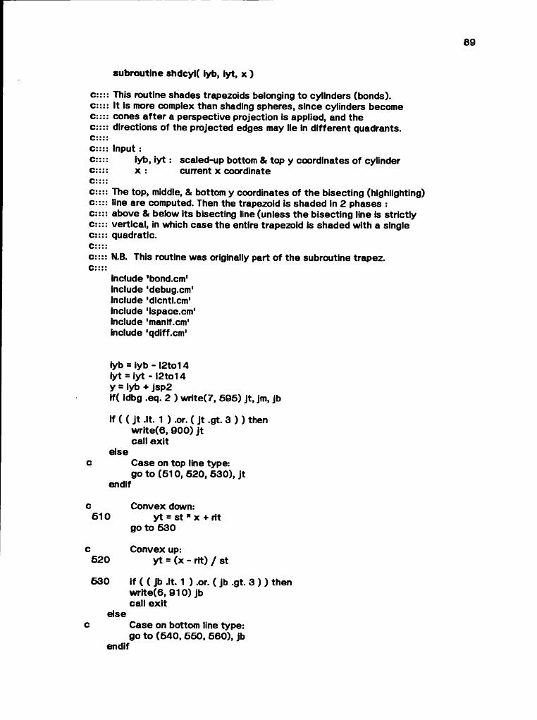
subroutine shdcyK iyb, iyt, x )
c:::: This routine shades trapezoids belonging to cylinders (bonds), c:::: It is more complex than shading spheres, since cylinders become c:::: cones a fte r a perspective projection is applied, and the c:::: directions of the projected edges may lie in d ifferent quadrants.c::::C:::: Input :c:::: iyb, i y t : scaled-up bottom & top y coordinates of cylinderc:::: x : current x coordinateC::::c:::: The top, middle, & bottom y coordinates of the bisecting (highlighting) c:::: line are computed. Then the trapezoid is shaded in 2 phases : c:::: above & below its bisecting line (unless the bisecting line is strictly c:::: vertical, in which case the entire trapezoid is shaded with a single C:::: quadratic.C::::c:::: N.B. This routine was originally part of the subroutine trapez.C::::
include 'bond.cm' include 'debug.cm'Include 'dicntl.cm'Include 'ispace.cm' include 'manif.cm* include 'qdiff.cm'
iyb = iyb - i2 to14 Iyt = Iyt - l2 to14 y = iyb + jsp2if( idbg .eq. 2 ) w rite(7, 5 9 5 ) jt , jm, jb
if ( ( Jt .It. 1 ) .or. ( j t .gt. 3 ) ) then w rlte (6 , 9 0 0 ) j t call e x it
elsec Case on top line type:
go to (5 1 0 , 5 2 0 , 5 3 0 ), j tendif
c Convex down:6 1 0 y t = st * x + rit
go to 5 3 0
c Convex up:5 2 0 y t = (x - rit) / st
6 3 0 if ( ( jb .It. 1 ) .or. ( jb .gt. 3 ) ) then w rite (6 , 9 1 0 ) jb call e x it
elsec Case on bottom line type:
go to (6 4 0 , 6 6 0 , 6 6 0 ), jb endif
c Convex down:6 4 0 yb = sb * x + rib
go to 5 6 0
c Convex up:6 6 0 yb = (x - rib) / sb
6 6 0 if ( ( jm .It. 1 ) .or. ( jm .gt. 3 ) ) then w rite(6 , 9 2 0 ) jm call ex it
elsec Case on middle line type:
go to (5 7 0 , 6 80 , 6 2 0 ), jmendif
Convex down:ym = sm * x + rim
go to 6 9 0
Convex up:ym = (x - rim) / sm if (ym .gt. rmaxl) ym = rmaxi
if (ym .it. -rmaxi) ym = -rmaxi if ( idbg .eq. 2 ) w rite(7, 6 9 5 ) iyb, iyt, yb, ym, y t iym = int( (ym - fjsp2) / fjsp ) * jsp if (iyb .gt. iym) then
nw = ( Iyt - iyb ) / jsp + 1 go to 8 0 0
else if (iy t .It. iym) thennw = ( iyt - iyb ) / jsp + 1
elsenw = (iym - iyb) / jsp + 1
end ifif (nw .le. 0 ) return if (markb .eq. ihoriz) go to 710
c====> Shade below highlight line with quadratics on vertical lines
call shvlin( y, ym, yb, nw ) y = y + nw * jsp go to 7 90
c====> Shade whole vertical segment with quadratics on horizontal lines c====> This loop is executed when the bisecting line of the trapezoid is c====> strictly vertical; a single quadratic can then be used to shade c====> the entire region.
c Straight line:6 2 0 nw = (iy t - iyb) / jsp + 1
if (nw .le. 0 ) return
6 7 0
6 8 06 9 0
cc
FES & single element plotting of nw elements computed in following loop

&
c
c6 3 0
c6 4 0
6 5 0
c
c6 5 5
c6 6 0
6 6 5
c
c6 7 0
c6 7 5
91
call output( jnoop, ifep l )call output( junpki, Ifep2 + nw )if ( idbg .eq. 2 ) w r ite (7 ,193 0 ) i fe p l , ifep2 + nw
do 7 0 0 J s 1, nw if ( idbg .eq. 2 )
write( 7, 1 93 2 ) y, rit, st, rim, sm, rib, sb If ( ( Jm .It. 1 ) .or. ( jm .gt. 3 ) ) then
write(6, 9 2 0 ) jm call exit
elseCase on middle line type: go to (6 3 0 , 6 40 , 6 4 0 ), jm
endif
Convex down:xm = (y - rim) / sm
go to 650
Convex up / straight line: xm = rim + y * sm
If ( ( Jt .It. 1 ) .or. ( j t .gt. 3 ) ) then write(6, 9 0 0 ) j t call exit
elseCase on top line type: go to (6 5 5 , 660 , 6 6 0 ), j t
endif
Convex down:x t = (y - rit) / st
go to 6 6 5
Convex up / straight line: x t = rit + y * st
if ( ( jb .It. 1 ) .or. ( jb .gt. 3 ) ) then write(6, 9 1 0 ) jb call exit
elseCase on bottom line type: go to (6 7 0 , 6 76 , 6 7 5 ), Jb
endif
Convex down:xb = (y - rib) / sb
go to 680
Convex up / straight line: xb = rib + y * sb
680 if ((x - xm) * (xb - xm)) 685, 690, 690
92
C < 0 :6 8 5 id = fs * (1 . - ((x - xm) / (x t - xm)) ** 2 ) + ad
go to 695
C >= 0 :6 90 id = fs * ( 1. - ((x - xm) / (xb - xm)) ** 2 ) + ad
c Plot 1 element in horizontal direction at exposurec level ad
6 9 5 call output( jemiti, ifp + id )if ( ¡dbg .eq. 2 ) write(7, 1 9 4 0 ) ifp, id, ifp + id y = y + f Jsp if ( idbg .eq. 2 )
& w rite( 7, 1 94 2 ) x, x t, xm, xb, y, fs, Id7 0 0 continue
if( idbg .eq. 2 ) w rite(7, 6 9 6 ) id, xb, xm, x t, x, fs, ad return
c====> Shade below highlight line with quadratics on horizontal lines
7 1 0 call shdbh( nw, x , y )7 9 0 If ( iyt .le. iym ) return
nw = (iy t - iym) / jsp
8 0 0 if (nw .le. 0 ) return if (markt .eq. ihoriz) then
c====> Shade above highlight line with quadratics on horizontal linescall shdah( nw, x , y )
else
c === -> Shade above highlight line with quadratics on vertical linescall shvlin( y, ym, yt, nw )
end if return
c====> Output formats
6 9 5 fo rm a t(3 i7 ,3 f1 0 .2 )1 9 3 0 format( 'trapez # 4 ' , 2110 )1 9 3 2 format ( ' y rlt s t rim sm rib sb: ', 7 (f1 0 .2 , 1 x ) )1 9 4 0 format( 'trapez # 5 \ 3110 )1 9 4 2 format( ' x x t xm xb y fs i d : 6 ( f 1 0 .2 , 1 x ), 110 )6 9 6 form at(2h d, ¡7, 6 f 10.2 )9 0 0 form at( ' shdcyl: Jt = ', I 5 , 1 out of range for computed go to' )9 1 0 format( ' shdcyl: Jb = ', I 5 , 1 out of range for computed go to* )9 2 0 format( 1 shdcyl: jm = ', 15,' out of range for computed go to1 )
end
subroutine shdsph( nw, iyb, x )
C:c:c:C:C:C:c:C:c:C:
This routine shades a trapezoid within a sphere, using a quadratic differencing algorithm.
Input :nw no. of pixels to shade in y direction iyb y coordinate of bottom of trapezoid
N.B. This routine was originally part of the subroutine trapez.
include 'debug.cm' include 'dicntl.cm' include 'ispace.cm' include 'manif.cm' include 'qdiff.cm1 include 'sphere.cm'
c====> FES - initiate plot of nw elementsc====> (elements are computed & emitted by quad)
call output( jnoop, ife s l ) call output( jpacki, ifes2 + nw ) if ( idbg .eq. 3 ) w rite(7, 1 9 1 0 )
y = yc - (iyb + jsp2 - i2to14 ) k1 = d - c * ( (x - x c ) ** 2 + y * y) k2 = e * y - fif ( idbg .eq. 2 ) w rite(7, 9 8 7 6 ) nw, k1 , k2, k3call quad( k1, k2, k3, nw )return
c==== Output formats
1 9 1 0 format( 1 trapez #2 ' )9 8 7 6 format( 6hparms , 4110 )
end
64
subroutine shvfin( y, ym, ybnd, nw )
c:c:C:C:C:C:C:C:C:C:C:c:
This routine shades entire region above/below highlight line with quadratics on vertical lines using the quadratic differencing algorithm.
In p u t:y bottom y coordinateym middle yybnd: y boundary value (either top or bottom)nw : no. of pixels to shade
MB. This routine generalizes 2 segments of nearly identical code fo r the above & below cases In the original version of trapez.
include 'dicntLcm' include 'ispace.cm'Include 'manif.cm' include 'qdiff.cm1
yd = y - ymctrbnd = c / (ym - ybnd) ** 2 k1 = c - ctrbnd * yd * yd ♦ a k2 = -ctrbnd * tjsp * (yd + fjsp) k3 = -ctrbnd * tjsq
c====> Initiate plot of nw elements computed & emitted by quadcall output( Jnoop, ifes l ) call output( Jpacki, Ifes2 + nw ) if ( idbg .eq. 2 ) w rite(7, 192 0 ) call quad( k 1 , k2, k3, nw ) return
c====> Output formats
1 9 2 0 format( 'trapez #3' )
end
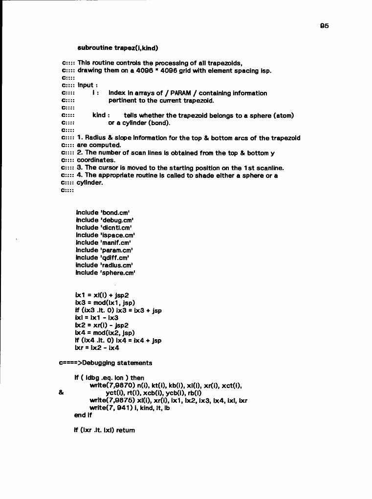
95
c:::: This routine controls the processing of all trapezoids,c:::: drawing them on a 4096 * 4096 grid with element spacing isp.c::::C:::: input :c:::: I : index in arrays of / PARAMI / containing informationc:::: pertinent to the current trapezoid.C::::c:::: kind: tells whether the trapezoid belongs to a sphere (atom)c:::: or a cylinder (bond).C::::c:::: 1. Radius & slope information for the top & bottom arcs of the trapezoid c:::: are computed.c:::: 2. The number of scan lines is obtained from the top & bottom y c.*::: coordinates.c:::: 3. The cursor is moved to the starting position on the 1st scanline, c:::: 4. The appropriate routine is called to shade either a sphere or a c:::: cylinder.
subroutine trapez(i,kind)
Include 'bond.cm' include 'debug.cm' include 'dicntl.cm' include 'ispace.cm' include 'manif.cm' include 'param.cm' include 'qdiff.cm' include 'radius.cm' include 'spherexm1
1x1 = xl(l) + jsp2b(3 = mod(ix1, jsp)if (ix3 .It. 0) ix3 = 1x3 + jspixl = 1x1 - ix3bc2 = xr(i) - Jsp2ix4 = mod(ix2, jsp)if (ix4 .It. 0) ix4 = ix4 + Jspbcr = ix2 - ix4
c====>Debugging statements
If ( idbg .eq. ion ) thenwrlte(7,9870) n(l), kt(i), kb(i), xl(l), xr(i), xct(l),
& yct(i), rt(i), xcb(i), ycb(i), rb(i)wrfte(7,9875) xl(i), xr(i), ix 1 ,1x2,1x3,1x4, ixl, Ixr write(7, 941) i, kind, It, lb
end if
if (ixr .It. ixl) return

66
It = kt(i)lb = kb(i)
If ( ( It .It. 1 ) .or. ( It .gt. 4 ) ) thenwrite(6, 9900) It call exit
elsec Top arc:
go to (900, 900, 910, 910), Itendif
c Convex down / up:600 srt = float( rt(i)) ** 2
go to 920
c Straight line / special case:610 slopt = float( xct(i) ) / rmaxi
620 if ( ( lb .It. 1 ) .or. ( lb .gt. 4 ) ) thenwrite(6, 9910) lb call exit
elsec Bottom arc:
go to (930, 930, 940, 940), lbendif
c Convex down / up:930 srb = float( rb(i) ) ** 2
go to 950
c Straight line / special case:640 stopb = float( xcb(i) ) / rmaxi
c====> This loop sweeps across the trapezoid horizontally, c====> generating vertical scan lines.
650 do 2 lx ~ ixl, Ixr, jspif( idbg .eq. ion .and. kind .eq. kcyl ) wrlte(7,391) ixl, Ixr, lxx = lx + Jsp2
If ( ( It .It. 1 ) .or. ( It .gt. 4 ) ) then write(6, 9900) It call exit
elsec Find top of quadratically shaded segment
go to (800, 810, 820, 830), Itendif
c Convex down:800 ysq = srt - (x - xct(i)) ** 2
yt = yct(l) + sqrt( abs(ysq) ) go to 850
c Convex up:

810 ysq = srt - (x - xct(i)) ** 2 yt = yct(i) - sqrt( abs(ysq) ) go to 850
c Straight line:820 yt = slopt * x + rt(i)
go to 850
c Special case:630 yt = (x - rt(i)) / slopt
850 If ( ( lb .It. 1 ) .or. ( lb .gt. 4 ) ) then write(6, 9910) lb call exit
elsec Find bottom of quadratically shaded segment
go to (860, 870, 880, 890), lbendif
Convex down:ysq = srb - (x - xcb(f)) ** 2
yb = ycb(i) + sqrt( abs(ysq) ) go to 430
Convex up:ysq = srb - (x - xcb(i)) ** 2
yb = ycb(i) - sqrt( abs(ysq) ) go to 430
Straight line:yb = slopb * x + rb(i)
go to 430
Special case:yb = (x - rb(i)) / slopb
yt = yt + r2to14 yb = yb + r2to14lyt = int( (yt + Jsp2) / jsp ) * Jsp - Jsp iyb = lnt( (yb + Jsp2) / Jsp) * jsp nw = (iyt - iyb) / jsp + 1If ( idbg .eq. ion ) write(7, 9874) yb, yt, iyb, iyt, ysq, nw If (nw .le. 0) go to 2
c====> Move CRT beam to following absolute positioncall output( jnoop, ipos ) call output( jsavex, Iyb ) call output( jsavey, lx + i2to14 )
if ( idbg .eq. ion ) write(7,1900)ipos, Iyb, ix + l2to14
if ( ( kind .It. 1 ) .or. ( kind .gt. 2 ) ) then wrlte(6, 9920) kind
660
870
880
890
430

«8 o8 «8 o8 «8
98
call exitelse
go to (440, 460), kindendif
c Shade Sphere:440 call shdsph( nw, lyb, x )
go to 2
c Shade Cylinder:460 call shdcyl( iyb, iyt, x )
2 continue
return
c====> Output formats
391 format(2h x, 3i6)941 format(2h t, 6I6)1900 formate 1 trapez #1 ', 3110 )9870 format( ' n = ', I3 /
& ' kt = ', ¡3 /& ' kb = ', I3 /& • xl = ', 110 /& ' x r s ' , n o /8. 'x c t= ',110 /& 'yet = ', ¡10 /& 1 rt = ', 110 /& 'xeb s ' ,110 /& 'ycb =', ¡10 /& ' rb = MO )9874 format ( 'yb = ', 1 pel 0.4 /
■yt = \ 1 pel 0.4 /'iyb = ', i10 /■iyt =',110 /■ysq = 1 pel 0.4 /■nw = ', 14 )
9 8 7 5 format( 2(1 pel 4.4, 1 x), 6i10 )9900 format( 'trapez: It = ', I5,1 out of range for computed go to' )9910 format( 'trapez: lb = ', I5, 1 out of range for computed go to1 )9920 formaté 'trapez: kind = ', 15, 1 out of range for computed go to' )
end
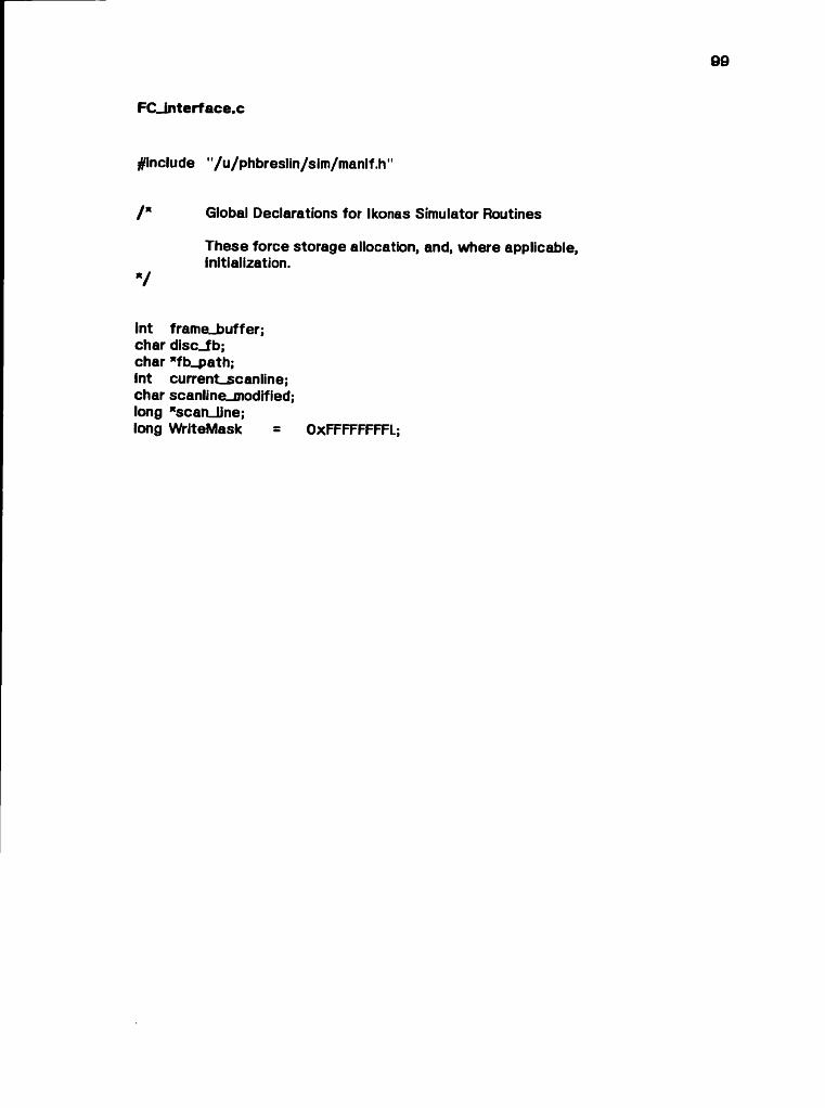
FC_interface.c
^include "/u/phbreslin/sim/manif.h "
/* Global Declarations for Ikonas Simulator Routines
These force storage allocation, and, where applicable, initialization.
7
int frame_buffer; char disc_fb; char *fb_path;Int current_scanline; char scanline_modified; long Nscan_line;long WriteMask = OxFFFFFFFFL;
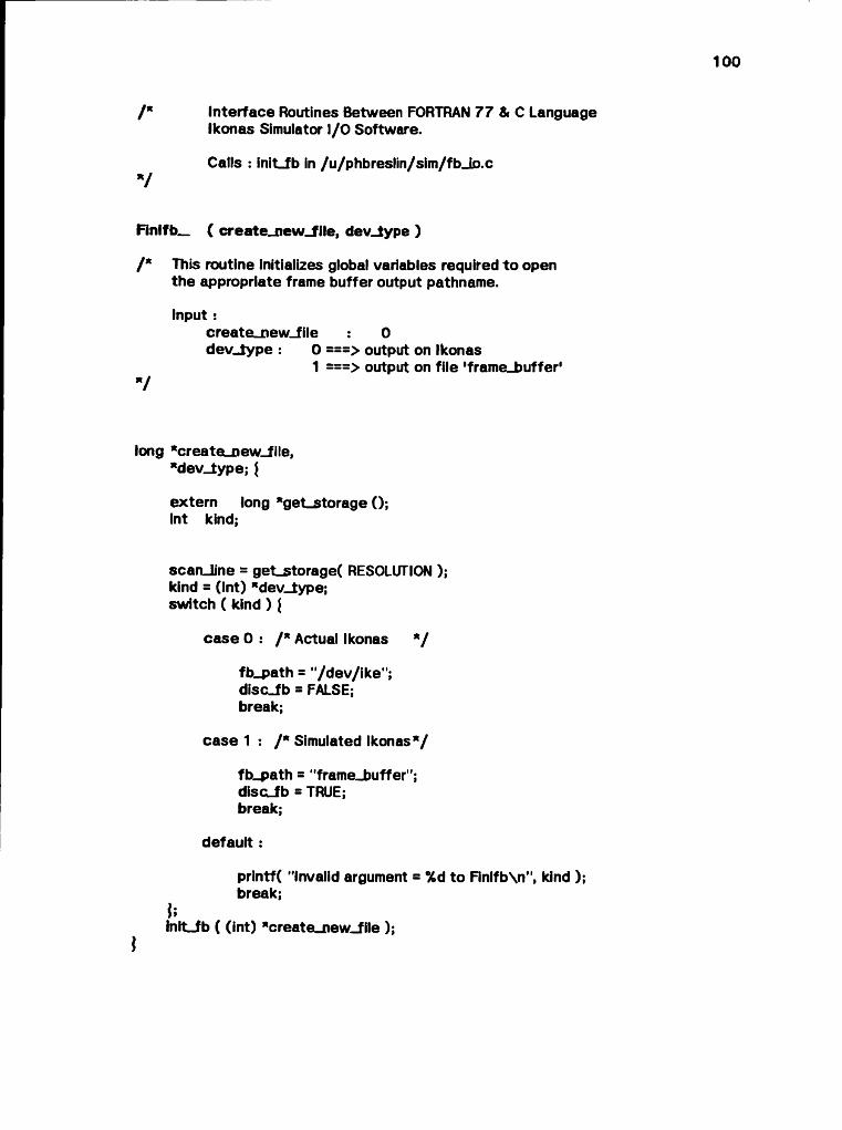
100
/* Interface Routines Between FORTRAN 77 & C LanguageIkonas Simulator I/O Software.
Calls : init_fb in /u/phbreslin/sim/fb_io.c
Finifb_ ( create_new_f ile, dev_type )/* This routine initializes global variables required to open
the appropriate frame buffer output pathname.
Input :create_new_file dev_lype : 0
1V
0> output on Ikonas> output on file 'frame_buffer'
long *create_new_file,*dev_type; \
extern long *get_storage (); int kind;
scan_line = get_storage( RESOLUTION ); kind = (int) *dev_type; switch ( kind ) {
case 0 : /* Actual Ikonas */
fb_path = "/dev/ike"; disc_fb = FALSE; break;
case 1 : /" Simulated Ikonas*/
fb_path = "frame_buffer"; d isoib = TRUE; break;
default:
printf( "Invalid argument = % 6 to Finlfb\n", kind ); break;
ulnit_fb ( (int) "create_new_file );
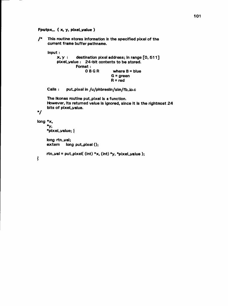
Fputpx— ( x, y, pixeLvalue )
/* This routine stores information in the specified pixel of the current frame buffer pathname.
input :x, y : destination pixel address; in range [0, 511]pixeLvalue : 24-bit contents to be stored.
Format :OBGR where B = blue
G = green R = red
Calls : put_pixel in /u/phbreslin/s!m/fbJo.c
The Ikonas routine put_plxe! is a function.However, Its returned value is ignored, since it is the rightmost 24 bits of pixeLvalue.
long "x,*y."pixeLvalue; \long rtn_val;extern long put_pixel ();
rtn_val = put_pixel( (int) *x, (int) *y, "pixeLvalue );

Fclofb_ () |
/* This routine closes the current Ikonas output pathname.V
close( frame_buffer );

static long * get_storage( nwords )
/ * This routine is used to allocate 1 scanline of storage, permitting output buffering to the Ikonas.Nothing is actually transmitted to the device (or file) until the scanline currently being accessed changes.
V
int nwords;i
long ’"memory;
lf( ¡(memory = (long I*)calloc( nwords, sizeof(long) )) )\
put_string( "\n** Out of memory **\n" ); exit();
lreturn( memory );
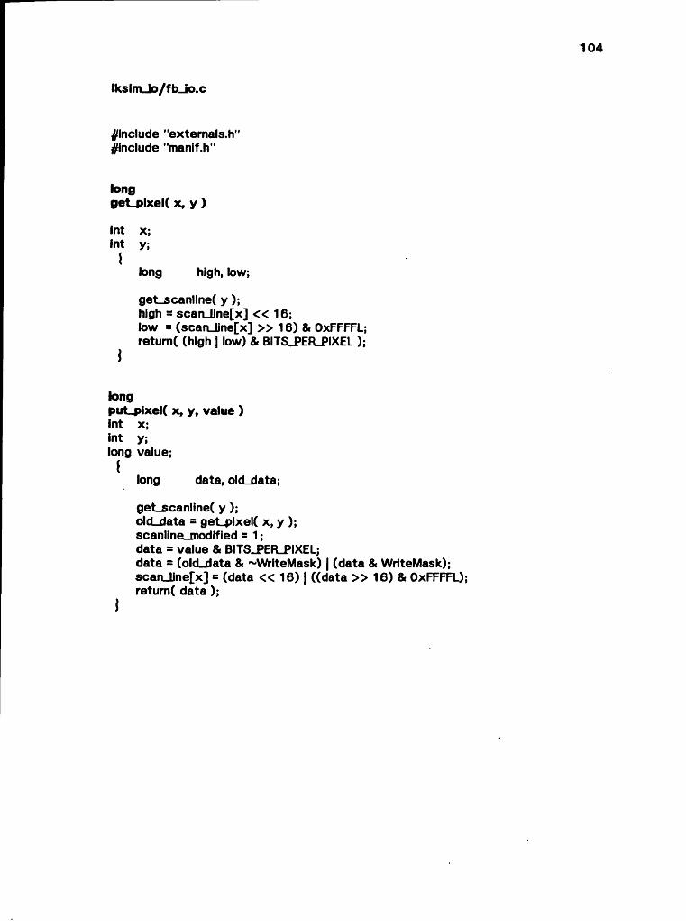
¡kslm_lo/fb_io.c
^include "externals.h" ^include "manif.h"
longget_pixel( x, y )
int X;Int y;
ílong high, low;
geLscanline( y );high - scan_Une[x] « 16;low = (scan_line[x] » 16) & OxFFFFL;retum( (high | low) & BITS_PER_PIXEL );
longput_pixel( x, y, value ) int x; int y; long value;
{long data, olcLdata;
get_scanline( y );olcLdata = geLplxel( x, y );scanline_modlfied - 1 ;data = value & BITS_PER_PIXEL;data = (olcLdata & ~WrlteMask) | (data & WriteMask);scan_line[x] = (data « 16) | ((data » 16) & OxFFFFL);retum( data );
J

105
init_fb( old_file )
int olcLflle;
char c;register Int i;
prlntf( "fb: %s\n", fb_path ); if( disc_fb && iolcLfile )
lf( (frame_buffer = creat( fb_path, 0x187 )) == -1 )l
put_string( "Could not create frame buffer file.\n" ); exlt(1);
j/*
creat opens for write only. We want read/write.7
close( framebuffer ); framebuffer = open( fb_path, 2 ); lseek( framebuffer, ONE_MEG_BYTES, 0 ); c = 0;wrlteC framebuffer, 8>c, 1 );
for( i=0; i < RESOLUTION; ++I )8can_line[i] = OL;
current-scanline = 0;J
elself( (framebuffer = open( fb_path, 2 )) == -1 )
put_string( "Could not open frame buffer!\n" ); if( disc_fb )
iput_string( "Attempting to create...\n" ); lnit_fb(0);
elseex1t(1);
ielse
current_scanllne = -1; scanlineunodified = 0; get_scanline(0);
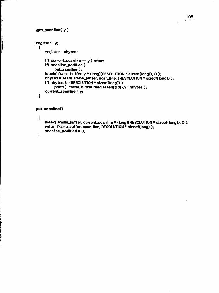
106
get_scanline( y )
register y;I
register nbytes;
lf( current_scan1ine == y ) return; if( scanline_modified )
put_scanline();lseek( frame_buffer, y * (long)(RESOLUTION * slzeof(long)), 0 ); nbytes = read( framelbuffer, scanJJne, (RESOLUTION * slzeof(long)) ); lf( nbytes != (RESOLUTION * sizeof(long)) )
printf( "framelbuffer read failed(%d)\n", nbytes ); current_scanllne = y;
put_scanline()i
lseek( frame_buffer, current_scanline * (long)(RESOLUTION * sizeof(long)), 0 ); write( framej>uffer, scanJine, RESOLUTION * sizeof(long) ); scanlineLjnodified = 0;
\