A project report on cam follower utility in internal combustion engine
24
A REPORT ON UTILITY OF CAM FOLLOWER IN SINGLE CYLINDER FOUR STROKE SPARK IGNITION ENGINE HARDWARE PROJECT REPORT 2014/15 SUBMITTED BY- GUIDE&CO-GUIDE PIYUSH KUMAR TIWARI 1101201022 DR. HARSHDEEP SHARMA GAURAV BHATI 1101201049 DR. KRISHNA VIJAY OJHA NITESH KUMAR JHA 1101201038 ABHISHEK KR. CHAUDHARY 1101201110 RITESH KUMAR SINGH 1101201060 VISHAL KUMAR 1101201042
-
Upload
galgotias-university -
Category
Engineering
-
view
1.063 -
download
45
Transcript of A project report on cam follower utility in internal combustion engine
A
REPORT ON UTILITY OF CAM FOLLOWER
IN SINGLE CYLINDER FOUR STROKE SPARK
IGNITION ENGINE
HARDWARE PROJECT REPORT 2014/15
SUBMITTED BY- GUIDE&CO-GUIDE
PIYUSH KUMAR TIWARI 1101201022 DR. HARSHDEEP SHARMA
GAURAV BHATI 1101201049 DR. KRISHNA VIJAY OJHA
NITESH KUMAR JHA 1101201038
ABHISHEK KR. CHAUDHARY 1101201110
RITESH KUMAR SINGH 1101201060
VISHAL KUMAR 1101201042
ACKNOWLEDGEMENT
We are deeply grateful to DR.HARSHDEEP
SHARMA AND DR.KRISHNA VIJAY OJHA Who
gave us a chance to model work on the topic of
cam/follower utility in single cylinder four stroke
S.I. engine. They provide us valuable suggestion
on this model for which we are highly obliged.
This model helps to the fresher students of
mechanical engineering to understand the basic
working and concept of cam/follower in engines.
We have try our best to ensure the model free of
error but small mistakes may be possible by
human mistake.
GROUP MEMBERS-
PIYUSH KUMAR TIWARI
GAURAV BHATI
NITESH KUMAR JHA
ABHISHEK KUMAR CHAUDHARY
RITESH KUMAR SINGH
VISHAL KUMAR
LIST OF CONTENT
1. Certificate
2. Acknowledgement
3. Introduction
4. Types of cam
5. Types of follower and geometry
6. Working and dimension analysis
7. Cost analysis and purpose
8. References.
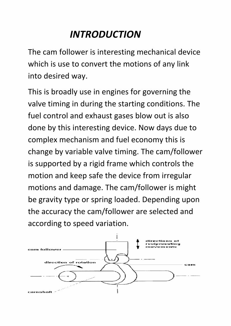
INTRODUCTION
The cam follower is interesting mechanical device
which is use to convert the motions of any link
into desired way.
This is broadly use in engines for governing the
valve timing in during the starting conditions. The
fuel control and exhaust gases blow out is also
done by this interesting device. Now days due to
complex mechanism and fuel economy this is
change by variable valve timing. The cam/follower
is supported by a rigid frame which controls the
motion and keep safe the device from irregular
motions and damage. The cam/follower is might
be gravity type or spring loaded. Depending upon
the accuracy the cam/follower are selected and
according to speed variation.
TYPES OF CAM
CAMS ARE CLASSIFIED ACCORDING TO-
1. SHPE.
2. FOLLOWER MOVEMENT.
3. MANNER OF CONSTRAINT OF THE FOLLOWER.
ACCORDING TO SHAPE-
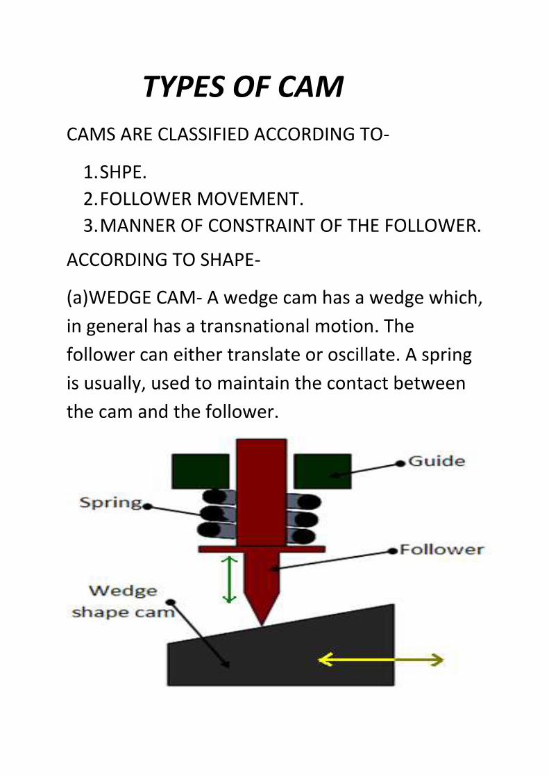
(a)WEDGE CAM- A wedge cam has a wedge which,
in general has a transnational motion. The
follower can either translate or oscillate. A spring
is usually, used to maintain the contact between
the cam and the follower.
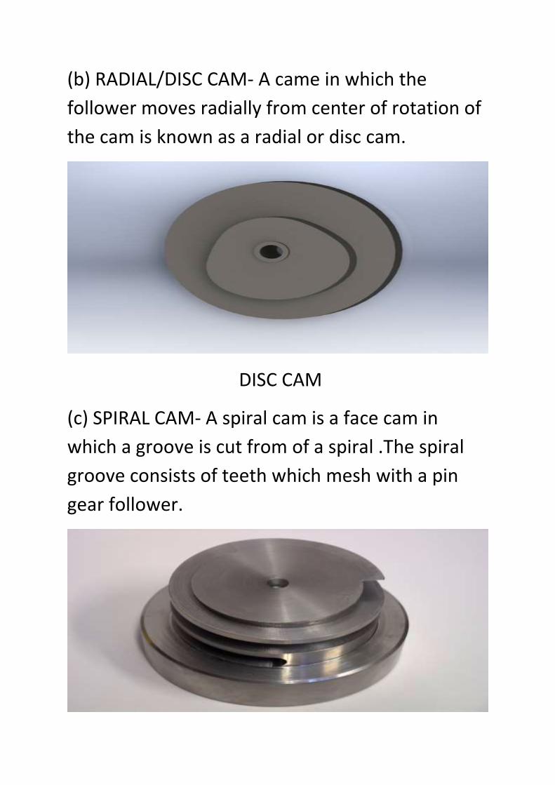
(b) RADIAL/DISC CAM- A came in which the
follower moves radially from center of rotation of
the cam is known as a radial or disc cam.
DISC CAM
(c) SPIRAL CAM- A spiral cam is a face cam in
which a groove is cut from of a spiral .The spiral
groove consists of teeth which mesh with a pin
gear follower.
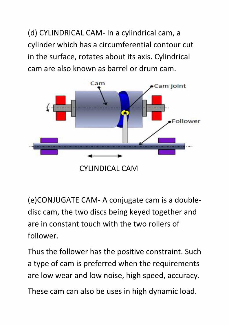
(d) CYLINDRICAL CAM- In a cylindrical cam, a
cylinder which has a circumferential contour cut
in the surface, rotates about its axis. Cylindrical
cam are also known as barrel or drum cam.
CYLINDICAL CAM
(e)CONJUGATE CAM- A conjugate cam is a double-
disc cam, the two discs being keyed together and
are in constant touch with the two rollers of
follower.
Thus the follower has the positive constraint. Such
a type of cam is preferred when the requirements
are low wear and low noise, high speed, accuracy.
These cam can also be uses in high dynamic load.
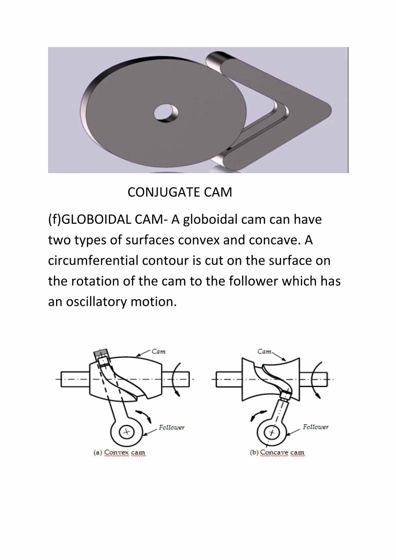
CONJUGATE CAM
(f)GLOBOIDAL CAM- A globoidal cam can have
two types of surfaces convex and concave. A
circumferential contour is cut on the surface on
the rotation of the cam to the follower which has
an oscillatory motion.
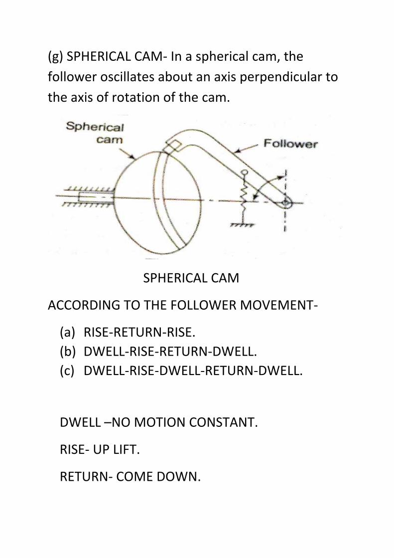
(g) SPHERICAL CAM- In a spherical cam, the
follower oscillates about an axis perpendicular to
the axis of rotation of the cam.
SPHERICAL CAM
ACCORDING TO THE FOLLOWER MOVEMENT-
(a) RISE-RETURN-RISE.
(b) DWELL-RISE-RETURN-DWELL.
(c) DWELL-RISE-DWELL-RETURN-DWELL.
DWELL –NO MOTION CONSTANT.
RISE- UP LIFT.
RETURN- COME DOWN.
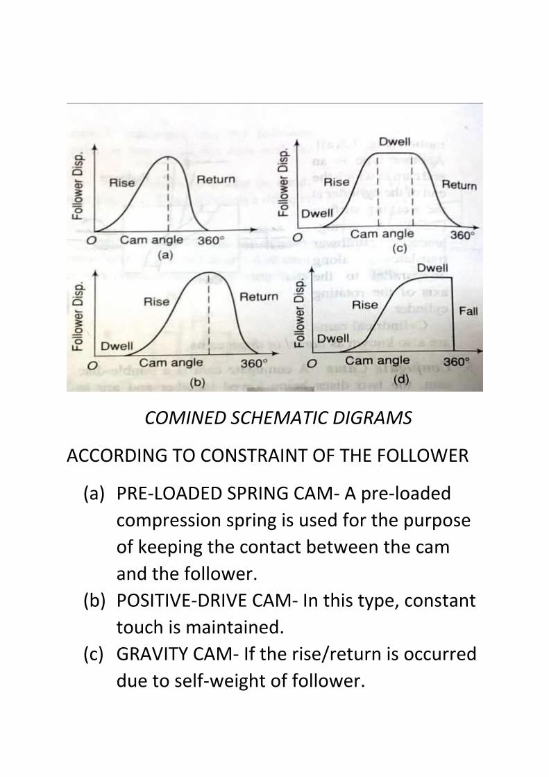
COMINED SCHEMATIC DIGRAMS
ACCORDING TO CONSTRAINT OF THE FOLLOWER
(a) PRE-LOADED SPRING CAM- A pre-loaded
compression spring is used for the purpose
of keeping the contact between the cam
and the follower.
(b) POSITIVE-DRIVE CAM- In this type, constant
touch is maintained.
(c) GRAVITY CAM- If the rise/return is occurred
due to self-weight of follower.
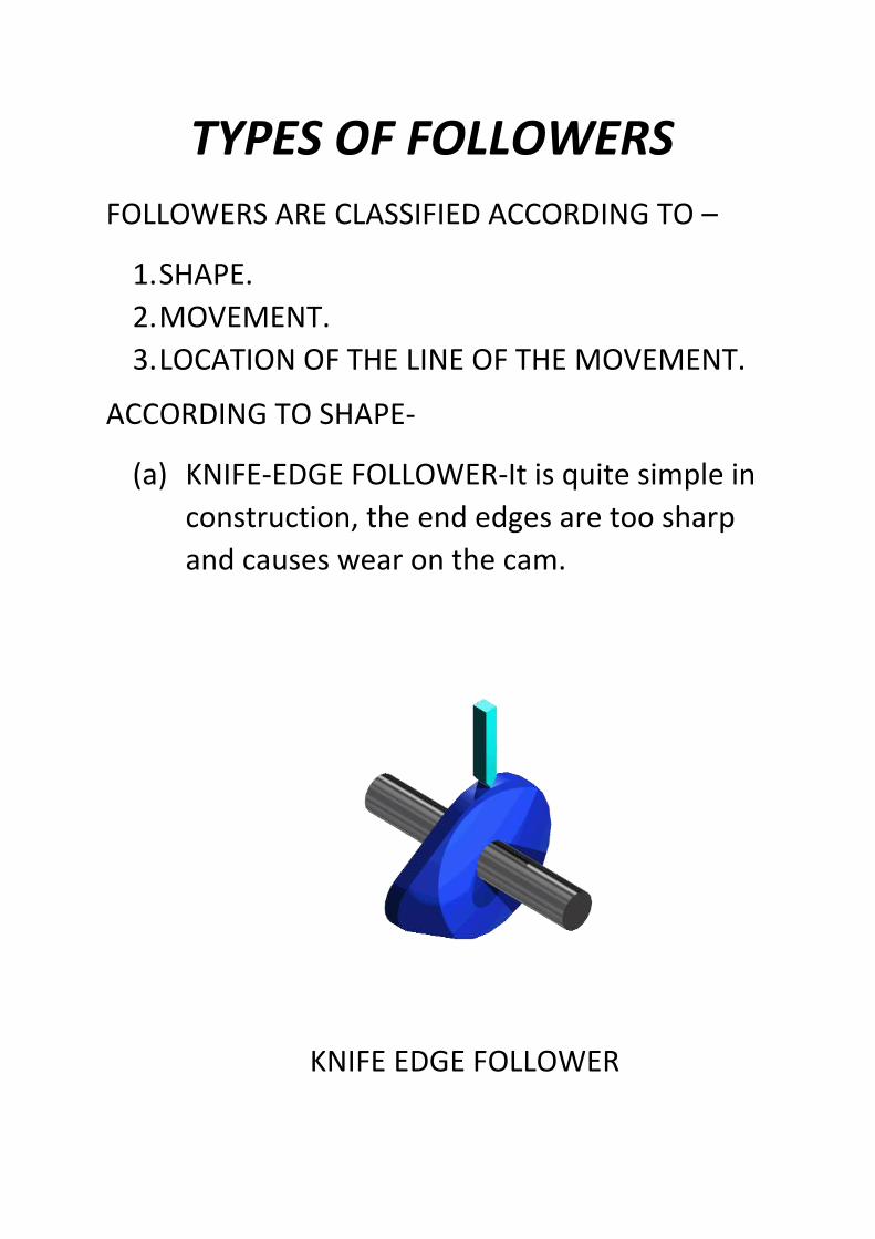
TYPES OF FOLLOWERS
FOLLOWERS ARE CLASSIFIED ACCORDING TO –
1. SHAPE.
2. MOVEMENT.
3. LOCATION OF THE LINE OF THE MOVEMENT.
ACCORDING TO SHAPE-
(a) KNIFE-EDGE FOLLOWER-It is quite simple in
construction, the end edges are too sharp
and causes wear on the cam.
KNIFE EDGE FOLLOWER
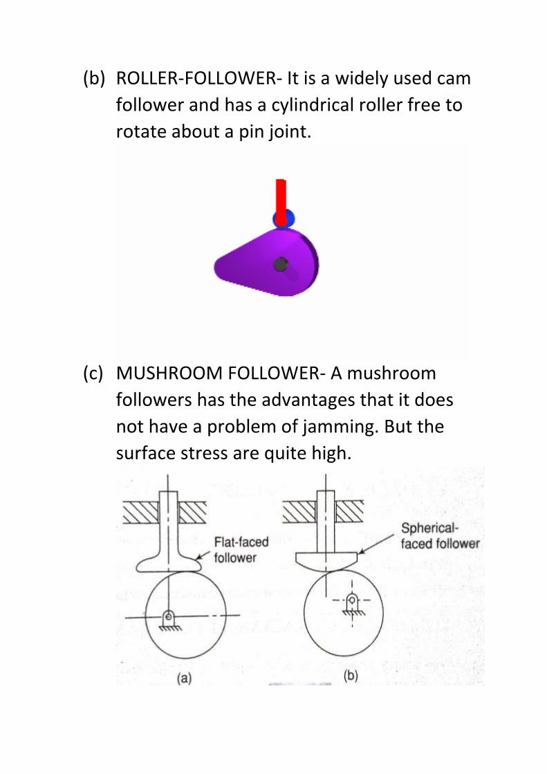
(b) ROLLER-FOLLOWER- It is a widely used cam
follower and has a cylindrical roller free to
rotate about a pin joint.
(c) MUSHROOM FOLLOWER- A mushroom
followers has the advantages that it does
not have a problem of jamming. But the
surface stress are quite high.
ACCORDING TO THE MOVEMENT-
(a) RADIAL FOLLOWER- In this, type as the cam
rotates, the follower reciprocates or
translates in the guides.
(b) OSCILLATING FOLLOWER- The follower is
pivoted at a suitable point on the frame and
oscillates as the cam makes the rotary
motion.
ACCORDING TO LOCATION OF LINE OF
MOVEMENT-
(a)RADIAL FOLLOWER-The follower is known as
a radial follower if the line of movement of the
follower passes through the center of rotation
of the cam.
(b)OFFSET FOLLOWER-If the line of movement
of the roller follower is offset from the center of
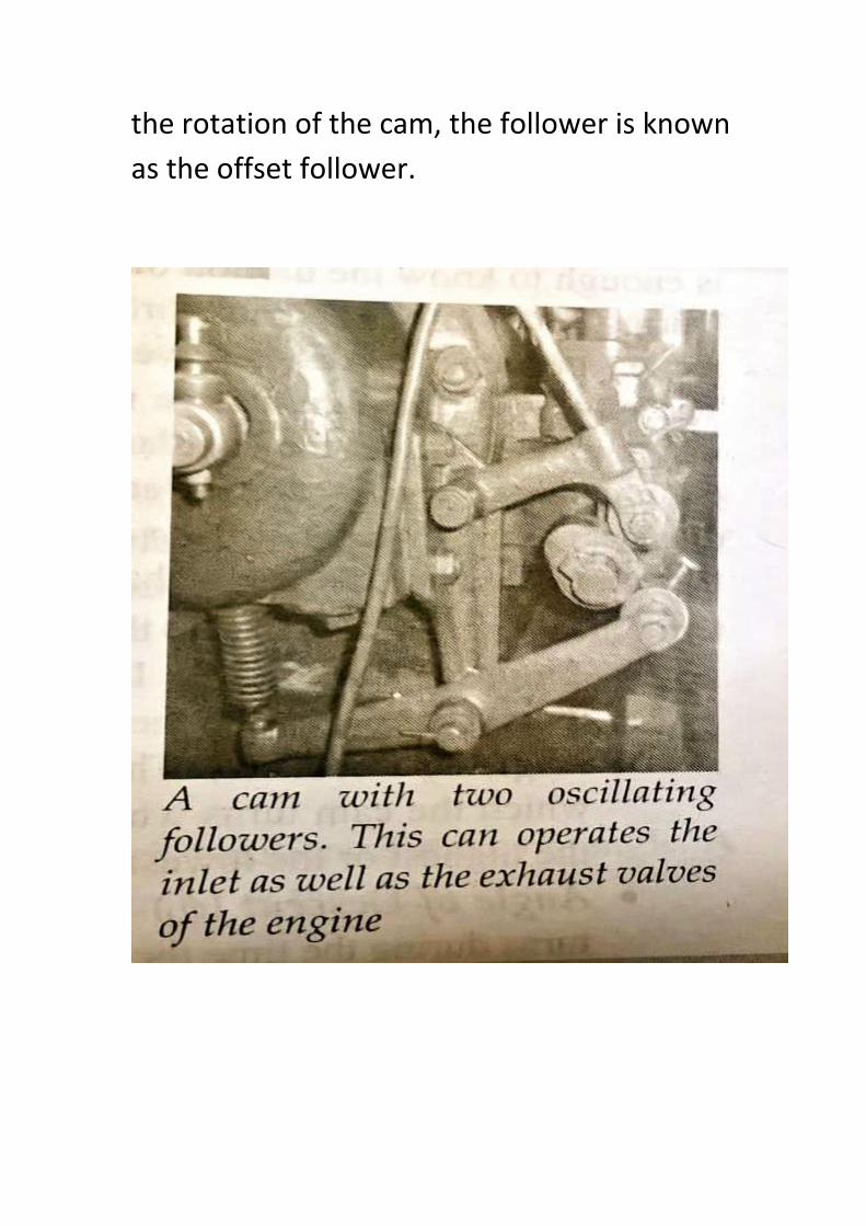
the rotation of the cam, the follower is known
as the offset follower.
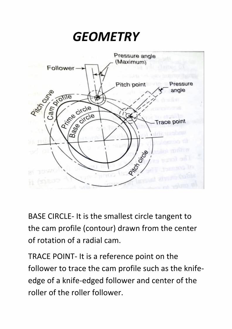
GEOMETRY
BASE CIRCLE- It is the smallest circle tangent to
the cam profile (contour) drawn from the center
of rotation of a radial cam.
TRACE POINT- It is a reference point on the
follower to trace the cam profile such as the knife-
edge of a knife-edged follower and center of the
roller of the roller follower.
PITCH CIRCLE- It is curve drawn by the trace point
assuming that the cam is fixed, and the trace
point rotates around the cam.
PRESSURE ANGLE- The pressure representing the
steepness of the cam profile, is the angle between
the normal to the pitch curve at a point and
direction of the follower motion. It varies in
magnitude in all instant of the follower motion.
PITCH POINT- It is the point on the pitch curve at
which the pressure angle is maximum.
PITCH CIRCLE- It is the circle passing through the
pitch point and concentric with the base circle.
PRIME CIRCLE- The smallest circle drawn tangent
to the pitch curve is known as the prime circle.
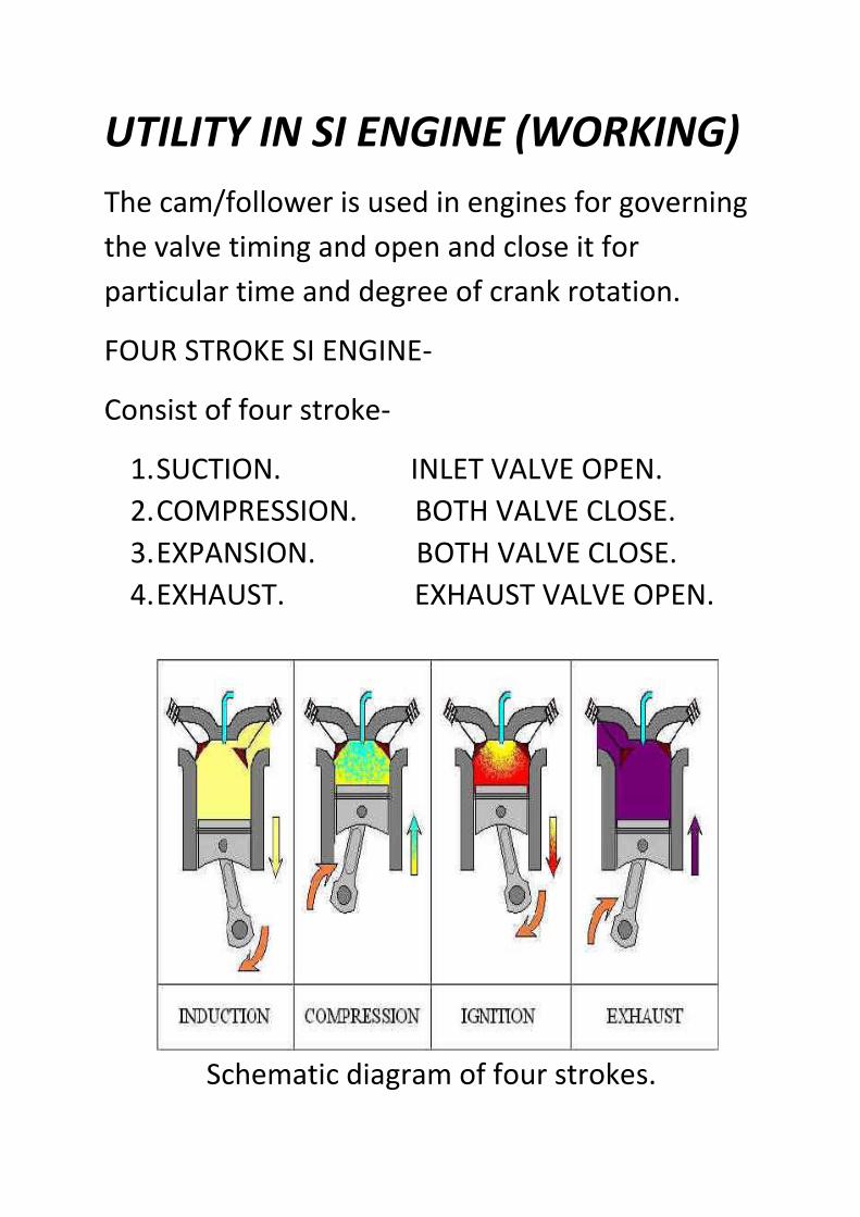
UTILITY IN SI ENGINE (WORKING)
The cam/follower is used in engines for governing
the valve timing and open and close it for
particular time and degree of crank rotation.
FOUR STROKE SI ENGINE-
Consist of four stroke-
1. SUCTION. INLET VALVE OPEN.
2. COMPRESSION. BOTH VALVE CLOSE.
3. EXPANSION. BOTH VALVE CLOSE.
4. EXHAUST. EXHAUST VALVE OPEN.
Schematic diagram of four strokes.
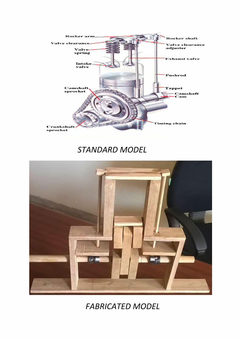
STANDARD MODEL
FABRICATED MODEL
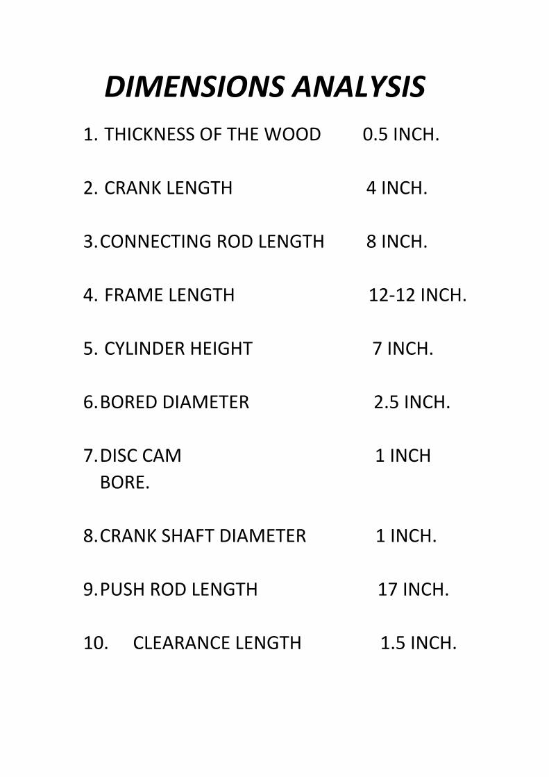
DIMENSIONS ANALYSIS
1. THICKNESS OF THE WOOD 0.5 INCH.
2. CRANK LENGTH 4 INCH.
3. CONNECTING ROD LENGTH 8 INCH.
4. FRAME LENGTH 12-12 INCH.
5. CYLINDER HEIGHT 7 INCH.
6. BORED DIAMETER 2.5 INCH.
7. DISC CAM 1 INCH
BORE.
8. CRANK SHAFT DIAMETER 1 INCH.
9. PUSH ROD LENGTH 17 INCH.
10. CLEARANCE LENGTH 1.5 INCH.
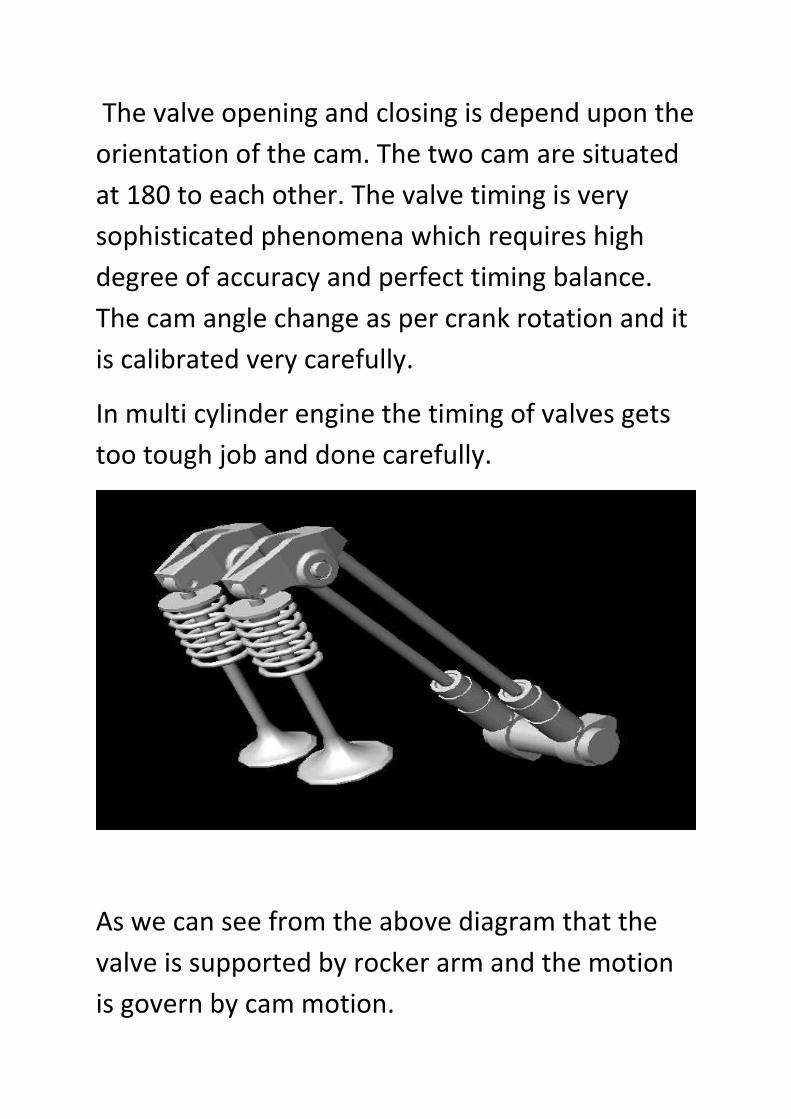
The valve opening and closing is depend upon the
orientation of the cam. The two cam are situated
at 180 to each other. The valve timing is very
sophisticated phenomena which requires high
degree of accuracy and perfect timing balance.
The cam angle change as per crank rotation and it
is calibrated very carefully.
In multi cylinder engine the timing of valves gets
too tough job and done carefully.
As we can see from the above diagram that the
valve is supported by rocker arm and the motion
is govern by cam motion.
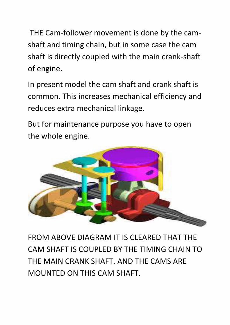
THE Cam-follower movement is done by the cam-
shaft and timing chain, but in some case the cam
shaft is directly coupled with the main crank-shaft
of engine.
In present model the cam shaft and crank shaft is
common. This increases mechanical efficiency and
reduces extra mechanical linkage.
But for maintenance purpose you have to open
the whole engine.
FROM ABOVE DIAGRAM IT IS CLEARED THAT THE
CAM SHAFT IS COUPLED BY THE TIMING CHAIN TO
THE MAIN CRANK SHAFT. AND THE CAMS ARE
MOUNTED ON THIS CAM SHAFT.
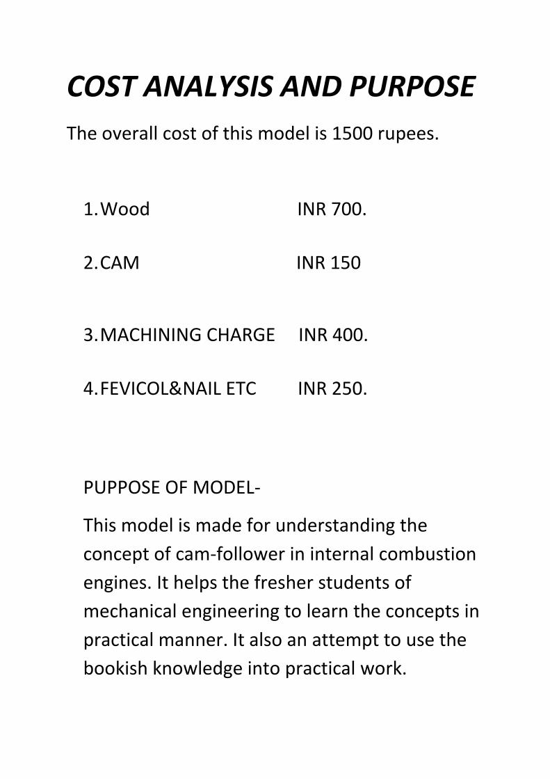
COST ANALYSIS AND PURPOSE
The overall cost of this model is 1500 rupees.
1. Wood INR 700.
2. CAM INR 150
3. MACHINING CHARGE INR 400.
4. FEVICOL&NAIL ETC INR 250.
PUPPOSE OF MODEL-
This model is made for understanding the
concept of cam-follower in internal combustion
engines. It helps the fresher students of
mechanical engineering to learn the concepts in
practical manner. It also an attempt to use the
bookish knowledge into practical work.
REFERENCES
1. I.C.ENGINE BY V.GANESHAN.
2. THEORY OF MACHINE BY
S.S.RATTAN.
3. GOOGLE IMAGES ON
CAM/FOLLOER.
4. LINK ADRESS-
http://en.wikipedia.org/wi
ki/Cam_follower.