A Programmable Optical Angle Clamp for Rotary Molecular Motors
12
A Programmable Optical Angle Clamp for Rotary Molecular Motors Teuta Pilizota,* Thomas Bilyard,* Fan Bai,* Masamitsu Futai, y Hiroyuki Hosokawa, y and Richard M. Berry* *Clarendon Laboratory, Department of Physics, University of Oxford, Oxford, United Kingdom; and y Futai Special Laboratory, Microbial Chemistry Research Center, Microbial Chemistry Research Foundation, CREST, Japan Science and Technology Agency, Kamiosaki, Shinagawa, Tokyo ABSTRACT Optical tweezers are widely used for experimental investigation of linear molecular motors. The rates and force dependence of steps in the mechanochemical cycle of linear motors have been probed giving detailed insight into motor mechanisms. With similar goals in mind for rotary molecular motors we present here an optical trapping system designed as an angle clamp to study the bacterial flagellar motor and F 1 -ATPase. The trap position was controlled by a digital signal processing board and a host computer via acousto-optic deflectors, the motor position via a three-dimensional piezoelectric stage and the motor angle using a pair of polystyrene beads as a handle for the optical trap. Bead-pair angles were detected using back focal plane interferometry with a resolution of up to 1°, and controlled using a feedback algorithm with a precision of up to 2° and a bandwidth of up to 1.6 kHz. Details of the optical trap, algorithm, and alignment procedures are given. Preliminary data showing angular control of F 1 -ATPase and angular and speed control of the bacterial flagellar motor are presented. INTRODUCTION Since their invention just over 20 years ago optical traps (1– 4) have been widely used for research purposes in both physics and biology, ranging from the cooling and trapping of neutral atoms (5) to manipulating live cells and viruses (6,7). More recently, optical traps have been extensively em- ployed in the experimental investigations of molecular motors (8,9). Their ability to apply piconewton forces to micron- sized particles, while simultaneously measuring displace- ment with nanometer precision, often makes them the best tool in practice. With the help of optical traps, the stepping behavior of the linear motors myosin (10), kinesin (11), and dynein (12) has been resolved. The implementation of ‘‘force clamps’’ and ‘‘position clamps’’ combining optical traps with controllable feedback systems provides more informa- tion about the motors’ mechanochemical cycles and working mechanisms (13,14). With similar goals in mind for rotary molecular motors, the bacterial flagellar motor, and F 1 F O - ATPase, we have designed an optical trap to act as an ‘‘angle clamp’’. We use a polystyrene bead duplex (bead pair) as a handle to apply external torque to rotary molecular motors. This technique allows us to achieve high temporal and angular resolution as well as great flexibility of control. The bacterial flagellar motor (bfm) is a rotary motor ;50 nm in diameter, embedded in the cell envelope and con- nected to an extracellular helical propeller (15,16). The mo- tor is powered by the flow of ions down an electrochemical gradient across the cytoplasmic membrane into the cell (the protonmotive force, pmf, or sodium-motive force, smf). It has recently been shown to rotate with 26 steps per rev- olution, with each step corresponding to a linear step of ;24 nm on the order of several milliseconds (17,18). F 1 F O - ATPase is an enzyme that utilizes the pmf or smf to syn- thesize ATP from ADP and P i (19,20). It is a complex of two motors, F O and F 1 , with an overall size of ;20 nm (21). Under normal conditions, the ion-driven, membrane-bound F O forces the ATP-driven, cytoplasmic F 1 in reverse, leading to ATP synthesis in F 1 . When separated from F O ,F 1 can hydrolyze ATP, leading to directly observable rotation of the g-subunit relative to the a 3 b 3 hexamer (22). Analysis of stepwise rotation consisting of 120° steps with 40° and 80° substeps (23,24) has led to a detailed understanding of the mechanism of the F 1 motor. With a 40-nm bead attached to F 1 , the 120° step corresponds to a linear step between 40 and 120 nm, and a 40° substep to between 13 and 40 nm. The larger 80° substep in F 1 rotation depends on ATP binding, and has a rate on the order of seconds for [ATP] in the nanomolar range. The smaller substep, however, is [ATP] independent and is on the order of milliseconds or less (23,25,26). Thus the temporal and spatial resolutions re- quired to detect features of interest in the rotation of these motors are on the order of milliseconds and tens of nano- meters, respectively. The stall torques of 40–60 pN nm and up to 1000–2000 pN nm, generated by F 1 (23,25) and the bfm (18,27), respectively, set the scale of torque required to con- trol these motors. Due to its large stall torque, the preferred method for ap- plying external torque to the bfm to date has been electroro- tation, with cells tethered to the surface by a flagellar filament and the cell body acting as the handle on the motor (28). External torque has been applied to F 1 by using magnetic tweezers to control the angle of magnetic beads, 470–700 nm in diameter, attached to the g-subunit. This technique has allowed the synthesis of ATP to be quantified (29,30), and Submitted June 10, 2006, and accepted for publication March 8, 2007. Address reprint requests to Richard M. Berry, Tel.: 44-0-1865-282559; Fax: 44-0-1865-272400; E-mail: [email protected]. Editor: David M. Warshaw. Ó 2007 by the Biophysical Society 0006-3495/07/07/264/12 $2.00 doi: 10.1529/biophysj.106.091074 264 Biophysical Journal Volume 93 July 2007 264–275
Transcript of A Programmable Optical Angle Clamp for Rotary Molecular Motors
A Programmable Optical Angle Clamp for Rotary Molecular Motors
Teuta Pilizota,* Thomas Bilyard,* Fan Bai,* Masamitsu Futai,y Hiroyuki Hosokawa,y and Richard M. Berry**Clarendon Laboratory, Department of Physics, University of Oxford, Oxford, United Kingdom; and yFutai Special Laboratory, MicrobialChemistry Research Center, Microbial Chemistry Research Foundation, CREST, Japan Science and Technology Agency, Kamiosaki,Shinagawa, Tokyo
ABSTRACT Optical tweezers are widely used for experimental investigation of linear molecular motors. The rates and forcedependence of steps in the mechanochemical cycle of linear motors have been probed giving detailed insight into motormechanisms. With similar goals in mind for rotary molecular motors we present here an optical trapping system designed asan angle clamp to study the bacterial flagellar motor and F1-ATPase. The trap position was controlled by a digital signalprocessing board and a host computer via acousto-optic deflectors, the motor position via a three-dimensional piezoelectricstage and the motor angle using a pair of polystyrene beads as a handle for the optical trap. Bead-pair angles were detectedusing back focal plane interferometry with a resolution of up to 1�, and controlled using a feedback algorithm with a precisionof up to 2� and a bandwidth of up to 1.6 kHz. Details of the optical trap, algorithm, and alignment procedures are given.Preliminary data showing angular control of F1-ATPase and angular and speed control of the bacterial flagellar motor arepresented.
INTRODUCTION
Since their invention just over 20 years ago optical traps (1–
4) have been widely used for research purposes in both
physics and biology, ranging from the cooling and trapping
of neutral atoms (5) to manipulating live cells and viruses
(6,7). More recently, optical traps have been extensively em-
ployed in the experimental investigations of molecular motors
(8,9). Their ability to apply piconewton forces to micron-
sized particles, while simultaneously measuring displace-
ment with nanometer precision, often makes them the best
tool in practice. With the help of optical traps, the stepping
behavior of the linear motors myosin (10), kinesin (11), and
dynein (12) has been resolved. The implementation of ‘‘force
clamps’’ and ‘‘position clamps’’ combining optical traps
with controllable feedback systems provides more informa-
tion about the motors’ mechanochemical cycles and working
mechanisms (13,14). With similar goals in mind for rotary
molecular motors, the bacterial flagellar motor, and F1FO-
ATPase, we have designed an optical trap to act as an ‘‘angle
clamp’’. We use a polystyrene bead duplex (bead pair) as a
handle to apply external torque to rotary molecular motors.
This technique allows us to achieve high temporal and
angular resolution as well as great flexibility of control.
The bacterial flagellar motor (bfm) is a rotary motor ;50
nm in diameter, embedded in the cell envelope and con-
nected to an extracellular helical propeller (15,16). The mo-
tor is powered by the flow of ions down an electrochemical
gradient across the cytoplasmic membrane into the cell (the
protonmotive force, pmf, or sodium-motive force, smf). It
has recently been shown to rotate with 26 steps per rev-
olution, with each step corresponding to a linear step of
;24 nm on the order of several milliseconds (17,18). F1FO-
ATPase is an enzyme that utilizes the pmf or smf to syn-
thesize ATP from ADP and Pi (19,20). It is a complex of two
motors, FO and F1, with an overall size of ;20 nm (21).
Under normal conditions, the ion-driven, membrane-bound
FO forces the ATP-driven, cytoplasmic F1 in reverse, leading
to ATP synthesis in F1. When separated from FO, F1 can
hydrolyze ATP, leading to directly observable rotation of the
g-subunit relative to the a3b3 hexamer (22). Analysis of
stepwise rotation consisting of 120� steps with 40� and 80�substeps (23,24) has led to a detailed understanding of the
mechanism of the F1 motor. With a 40-nm bead attached to
F1, the 120� step corresponds to a linear step between 40 and
120 nm, and a 40� substep to between 13 and 40 nm. The
larger 80� substep in F1 rotation depends on ATP binding,
and has a rate on the order of seconds for [ATP] in the
nanomolar range. The smaller substep, however, is [ATP]
independent and is on the order of milliseconds or less
(23,25,26). Thus the temporal and spatial resolutions re-
quired to detect features of interest in the rotation of these
motors are on the order of milliseconds and tens of nano-
meters, respectively. The stall torques of 40–60 pN nm and up
to 1000–2000 pN nm, generated by F1 (23,25) and the bfm
(18,27), respectively, set the scale of torque required to con-
trol these motors.
Due to its large stall torque, the preferred method for ap-
plying external torque to the bfm to date has been electroro-
tation, with cells tethered to the surface by a flagellar filament
and the cell body acting as the handle on the motor (28).
External torque has been applied to F1 by using magnetic
tweezers to control the angle of magnetic beads, 470–700 nm
in diameter, attached to the g-subunit. This technique has
allowed the synthesis of ATP to be quantified (29,30), and
Submitted June 10, 2006, and accepted for publication March 8, 2007.
Address reprint requests to Richard M. Berry, Tel.: 44-0-1865-282559;
Fax: 44-0-1865-272400; E-mail: [email protected].
Editor: David M. Warshaw.
� 2007 by the Biophysical Society
0006-3495/07/07/264/12 $2.00 doi: 10.1529/biophysj.106.091074
264 Biophysical Journal Volume 93 July 2007 264–275

the properties of the ADP-inhibited state to be investigated
(31). These methods have drawbacks, however. The cell
body is a large handle, and therefore requires extremely large
torques to attain the high speeds (;300 Hz) that are charac-
teristic of the flagellar motor. Furthermore, the size of these
handles and the way in which torque is applied do not lend
themselves to the high spatial and temporal resolutions that
are possible with optical traps. For example, the typical res-
olutions reported using magnetic beads are several seconds
and 5� (31).
There is one report of the use of optical tweezers to exert
torque on a rotary motor, to measure the stall torque of the bfm
(32), and two similar reports of the use of tweezers to study the
properties of the bfm hook and filament (33,34). In these
experiments torque was applied to the motor in the form of
linear force on the trapped particle. This situation is analogous
to tightening a nut with a wrench. The trap is akin to hand
holding the wrench, the cell body is the wrench, and the
opposing reactive force that completes the couple is generated
by the link between the motor and the surface. There are
several reports of methods that apply torque directly to mi-
croscopic objects with optical tweezers. Because laser beams
can carry spin and orbital angular momentum, torque can be
exerted on a microscopic object if angular momentum is
exchanged between the beam and the particle upon scattering.
This has been achieved by exchange of the following: spin
angular momentum with birefringent particles (35–40); spin
angular momentum with asymmetrically shaped particles
(41–43); orbital and spin angular momentum simultaneously
with absorbing particles (44,45). Rotation within optical
tweezers (by rotating an asymmetric interference pattern or a
high-order laser mode, by the use of an elliptical beam, or by
rotating an aperture (46–49)) and microfabricated chiral
scattering particles that act as optical ‘‘windmills’’ have also
been reported (50). These methods have several drawbacks,
however. The need for special microparticles, like birefrin-
gent or ‘‘windmill’’ particles, limits the practicality of the
method and potentially raises problems with attaching par-
ticles to rotary molecular motors. Techniques using energy
absorption are limited due to heating, and methods that rely on
rotationwithinoptical tweezers requiremorecomplicated trap-
ping systems to generate specialized beams. Shaped particles
and beams carrying orbital angular momentum have typical
dimensions of several microns, and thus the viscous drag on
trapped particles limits the response time of these particles to
changes in torque. Modulation of shaped beams generated by
micromirror or liquid-crystal technologies also limits the time
resolution of these techniques.
Our system uses a digital signal processing board for
control of the optical trap and allows us to achieve control of
the rotation angle of bead pairs with a bandwidth up to 1.6
kHz and angular precision of 2�, while at the same time
affording great flexibility when choosing and designing feed-
back algorithms for rotary molecular motors. We describe
and characterize alignment and calibration of our technique
and implementation of nonlinear feedback algorithms. We
demonstrate the capability of our method to observe fluctua-
tions in the bfm most likely caused by incorporation and
removal of individual torque-generating units, to control the
speed of the bfm, and to control the angle of the rotating
g-subunit of F1. We discuss complications related to calibra-
tion and mechanical damage to motors using our method,
and conclude that it will be a useful tool in future experi-
ments to investigate in detail the mechanism of rotary mo-
lecular motors.
METHODS
Instrument design
The instrument consists of a custom-built inverted microscope and two
lasers for detection and trapping (51). Bright-field imaging uses a high-
power light-emitting diode (Luxeon Star LEDs, Alberta, Canada), high N.A.
condenser (MEL 30920, Nikon, Tokyo, Japan) and objective (Plan Fluor
1003 / 0.5–1.3 oil iris, Nikon), and a high-sensitivity ½-inch black and
white charge-coupled device video camera (LCL-902K, Watec, Orange-
burg, NY). The microscope stage was designed to be light and compact
to minimize drift and vibration. Microscope slides holding specimens
are attached to a metal plate mounted on a three-axis piezoelectric stage
(P-611.3S nanocube with E-664 LVPZT amplifier/servo-driver, 100 mm
travel in x, y, z, 1 nm resolution, with a settling time of a few milliseconds,
Physik Instrumente, Karlsruhe, Germany), which is in turn mounted on
a lockable three-axis dovetail stage (Newport, Didcot, UK) for coarse
positioning.
Position detection is by back-focal-plane interferometry (52) using a laser
beam (helium-neon, 632 nm, 17 mW, Coherent, Santa Clara, CA) focused
into the specimen plane by the objective and collimated onto the face of a
quadrant photodiode (QD) (UDT Sensors, Hawthorne, CA). After ampli-
fication the QD signals are passed through antialiasing first-order prefilters
with time constants ranging from 0.625 ms to 6.25 ms and digitized at an
appropriate sample rate (53). Detector range can be increased from 400 to
1200 nm at the expense of sensitivity by reduction of the laser beam width
(using a detector beam iris). The intensity of the detector laser is controlled
by the iris aperture and neutral density filters, according to the requirements
of particular experiments.
The optical trap is formed by a near-infrared Ytterbium fiber laser (PYL-
3-LP, 1064 nm, 3 W continuous wave, IPG Photonics, Pittsfield, MA),
collimated by the manufacturer, with ,3% power fluctuation in 4 h. We
measured pointing fluctuations of this laser of ;2.5 mrad (rms) in 1 h, with
the spectral characteristics of white noise above ;30 Hz and 1/f noise
below ;30 Hz. The intensity of the trapping laser was varied via the diode
current and the combination of a half-wave plate and polarizing beam
splitter. Fine control of the trapping laser is achieved with acousto-optic
deflectors (AOD) AA.DTS.XY.250 at 1064 nm, AA.DDS.60-90.XY driver,
Opto-Electronique, Orsay, Cedex, France), positioned in a plane conjugate
to the back focal plane of the objective. The angular range and resolution
of the AOD are 49 mrad and 24.9 mrad, respectively. The smallest
movement of the trapping laser is 9 nm, and the AOD response time is
0.1 ms.
Data acquisition, feedback calculations, and control of the optical trap
were all performed by a digital signal processing board ((DSP) SI-C33DSP-
PCI, 150 MHz processor speed with SI-DSP6433R2-PCI daughter module,
16 analog input channels, four analog output channels with sampling rates
up to 50 kHz, Sheldon Instruments, San Diego, CA) installed in a host com-
puter (1.8 GHz processor, 1 GB RAM) running Windows 2000. The board
was programmed using a software package, QuVIEW, provided by the
manufacturer. Feedback programs on the DSP board were run at 10 kHz
sampling rate unless otherwise stated. Analog output channels from the DSP
An Optical Angle Clamp 265
Biophysical Journal 93(1) 264–275
daughter module were converted to digital for the AOD control by a custom-
made analog to digital converter that gave a scan range and resolution of
27.5 MHz and 15.3 kHz, respectively, corresponding to 44.9 mrad and 24.9
mrad beam deflection and 16.5 mm and 9 nm displacement of the optical
trap. For typical rotational trajectories of 100–1000 nm beads attached to
motors, 9 nm corresponds to an angular resolution of 1–10�, depending on
the radius of the circle along which the trapping laser is moved.
The trapping laser was chosen for low cost, high power, and the relatively
low levels of laser-induced photodamage to biological samples at this
wavelength (54). The helium-neon laser used for detection, with its shorter
wavelength, allows a smaller focused spot and therefore improved detector
sensitivity, especially for beads with diameters below ;500 nm. It also has
excellent beam quality and avoids potential difficulties with effective low-
pass filtering (8–9 kHz) that can occur with silicon photodiodes and 1064-
nm lasers (55,56). We characterized the photodamage caused by the detector
laser by recording laser-induced changes in the speed of a bead attached to a
rotating flagellar filament of Escherichia coli (18) over the range of laser
powers used (20–150 mW in the objective back-focal-plane). Using a speed
reduction of 5% to define a threshold for laser damage, we were able to
record for 1.5–2 min at 150 mW and for 5–10 min at 20 mW before
observing any laser damage. By contrast, previous work has shown that
similar speed recordings using a laser at 1064 nm can be extended for hours
without observable laser damage (27). Protein motors such as F1 are
typically less sensitive to photodamage than live cells, and can be protected
by the addition of singlet-oxygen scavengers (22) if necessary.
Alignment and calibration of the detectorand AOD
The dimensionless signal (X,Y) obtained from the detector by bfp
interferometry of a single bead was calibrated and the effect of the bead
height (focus, z) on the (X,Y) signal measured as described previously
(51,52). At the beginning of each experiment z¼ 0 was defined such that the
average brightness of the bright-field image of the bead was similar to the
background; thus, beads appeared gray at z¼ 0, black at z . 0 (by definition,
when the microscope and laser focus was in the sample buffer), and white at
z , 0 (focus in the coverglass), as illustrated in Fig. 2 c. By setting z ¼ 0 by
eye 20 times each for nine different beads and recording the spread of actual
heights read from the calibrated piezoelectric stage, we estimated that this
procedure sets z¼ 0 with an accuracy of ;30 nm. This is comfortably within
the range of ;400 nm over which the variation of X or Y with z is negligible
(data not shown), therefore we neglected any possible effects of z drift on the
detector response (X,Y).
We aligned the QD and AOD in the following way. 1), We moved a bead
stuck to the coverslip surface through the detector laser focus with the piezo
stage and defined the center of the detector beam as the midpoint of the single-
valued range of the X and Y signals. 2), With the bead at this center, we set Xand Y to zero by adjustment of a mirror that steers the detector laser beam onto
the QD. 3), We repeated steps 1 and 2 several times to remove any sensitivity
to the initial state of alignment. 4), With the AOD set at the center driving
frequency and the stuck bead replaced by a bead trapped a few microns from
the coverslip, we again set X and Y to zero. The bead position, (x, y), was
calculated in real time on the DSP board from the signal (X,Y) using a fifth-
order polynomial fit (51,52), with fit parameters obtained by scanning the
same bead (or another bead of the same size in the same sample) with the AOD
immediately before each experiment.
Trap stiffness
We calibrated the trap stiffness for single beads using either Brownian
motion of the bead and the Principle of Equipartition of Energy (52), or by
fitting the power spectrum of the Brownian motion to a model that accounts
for discrete sampling of the data, low-pass filtering by the QD, and inertial
effects from the entrained fluid surrounding the bead (52,53,57). One
unavoidable property of AOD is that the intensity of the deflected beam
varies with the angle of deflection. We were able to limit this intensity
variation over the full range of the AOD to ,8% by choosing the appropriate
driving amplitude for the range of frequencies used. The remaining variation
was characterized by measuring the trap stiffness at different positions, and
was found to follow the intensity variation as expected.
Feedback algorithms
To control the position of a single trapped bead in two dimensions we used
the standard proportional-integral feedback algorithm (58). To control the
angle coordinate of a bead or a bead pair, ub, we used:
ut;n ¼u�t;n : ju�t;n � ubj, uMax
ub;n � uMax : ðu�t;n � ub;nÞ, � uMax
ub;n 1 uMax : ðu�t;n � ub;nÞ. uMax
;
8<: (1)
where
u�t;n ¼ us;n � Kpðub;n � us;nÞ � Ki +
n
j¼0
ðub;j � us;nÞ:
ux,y are angle coordinates of the trap, bead (or bead pair), and set point
(x ¼ t, b, s, respectively) for a sample point indicated by the index y, and Kp
and Ki are proportional and integral feedback parameters. uMax is a constant.
The radial coordinate of the trap position remains constant. This nonlinear
algorithm ensures that the angle between the trap and the bead (proportional
to torque) never exceeds uMax (in our experiments typically 90�) and thus
that the torque on the bead will be in the correct direction even for large
error signals and gain.
Feedback bandwidth, fFB, is limited by the trap stiffness at low laser
power and at higher laser power by the delays due to the finite AOD re-
sponse time and the computational time on the DSP board. fFB increased
with Kp and Ki up to a maximum of ;1=4 floop, where floop is the overall
feedback execution frequency, after which the oscillations at ;1=4 floop
were observed. This is in agreement with predictions from a simple
calculation for an analog first-order system using the methods of Bechhoefer
(58), with the effect of delays taken into account.
Bead-pair preparation
We used amino-functionalized, biotinylated, and plain polystyrene micro-
spheres (diameter 500 nm, Polysciences, Eppelheim, Germany). Biotinylated
microspheres (beads) were prepared by incubation of amino-functionalized
beads, 1% by volume, for 2 h at room temperature with rolling, in 100 mM
sodium bicarbonate buffer pH ¼ 8.05 plus 2 mM 6-(biotinamidocaproyla-
mido)caproic acidin-hydroxysuccinimideester (Sigma-Aldrich, Gillingham,
UK) added as 100 mM stock in dimethyl sulfoxide (Sigma-Aldrich), fol-
lowed by resuspension in storage buffer (10 mM HEPES/NaOH, pH ¼ 7.8).
Bead pairs were prepared by incubating beads in media with high salt con-
centrations, which is assumed to collapse the Debye layer and to allow beads
to stick to each other by van der Waals interactions. We used 100–340 mM
KCl for plain polystyrene beads and 100 mM MgCl2 for biotinylated amino
beads, both in storage buffer. Bead concentrations were between 0.5% and
2% by volume. After adding salt, beads were sonicated for 4–10 min and
washed three times in storage buffer to a final concentration of ;0.5%.
Immediately after washing 10–15% of all objects in the solution were bead
pairs. The bead pairs were separated from single beads and clumps con-
taining more than two beads by sucrose gradient centrifugation and washed
three times in storage buffer. Immediately after gradient separation 60–80%
of all objects in the solution were bead pairs.
266 Pilizota et al.
Biophysical Journal 93(1) 264–275
Bead-pair assay
Biotinylated bead pairs were attached to the surface of a coverslip as follows.
The coverslip was cleaned with saturated KOH in 95% ethanol before use. A
tunnel slide was constructed using double-sided adhesive tape to define a
channel between the coverslip and a microscope slide, filled with Buffer A
(10 mM MOPS/KOH, 2 mM MgCl2, 50 mM KCl, pH 7) containing 6 mg/ml
bovine serum albumin (Sigma-Aldrich) and incubated for 1 min. 4 mM
streptavidin (Sigma-Aldrich) in Buffer A was then added and incubated for
10 min. After washing with Buffer A, 0.5% biotinylated bead pairs in Buffer
A were added and incubated for 10 min.
F1 rotation assay
E. coli F1 with six histidine residues introduced into the a-subunit and two
cystine mutations in g-subunit was purified as described (59,60). Micro-
scope coverslips were cleaned and assembled into tunnel slides as described
above (BSA surface), or cleaned as described above and then a), coated with
nitrocellulose (collodion solution, Sigma-Aldrich) and 1 mM Ni-NTA HRP
(Qiagen, Crawley, UK) (HRP surface); or b), functionalized by a silane
coupling agent before reaction with 10–15 mg/ml maleimide-C3-NTA
(Dojindo, Kumamoto, Japan) and then 10 mM NiCl2, essentially as de-
scribed (29,61) (silane surface). The coverslips were then assembled into
tunnel slides as described above. The following were flowed through the
channel: 1 nM F1 in Buffer A1BSA, wait 10 min; Buffer A1BSA; 4 mM
streptavidin (Sigma-Aldrich) in Buffer A, wait 10 min; Buffer A1BSA;
0.5% biotinylated bead pairs in Buffer A1BSA, wait 10 min; Buffer
A1BSA; 24 mM Mg-ATP in Buffer A1BSA.
E. coli rotation assay
Cells of E. coli strain KAF95 (expressing flagellar filaments that sponta-
neously stick to plain polystyrene beads and flagellar motors that do not
switch direction (28)) were grown, prepared, and labeled with plain
polystyrene beads or bead pairs attached to truncated flagellar filaments as
described (18).
TWO-DIMENSIONAL FEEDBACK CONTROL OFA SINGLE BEAD
If a single bead is rigidly attached to the rotor of a molecular
motor, then the only degree of freedom is the bead-rotor link
angle and thus controlling the position of the center of the
bead controls the motor angle as desired. However, beads are
usually attached to the bfm via the sticky flagellar filament
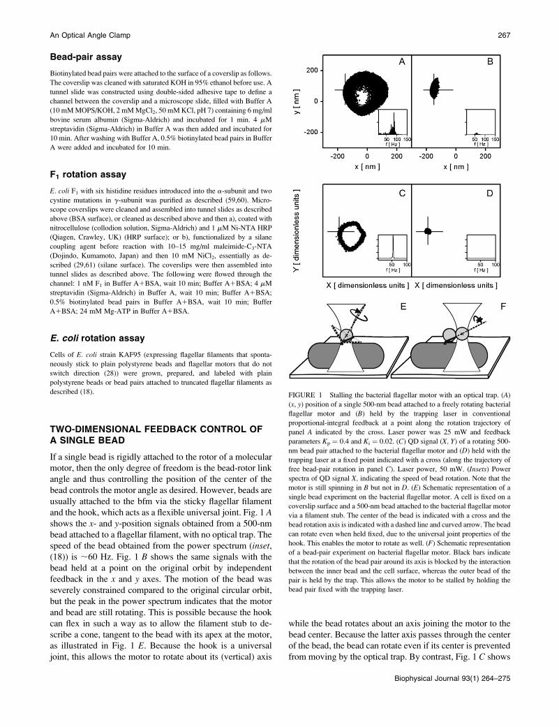
and the hook, which acts as a flexible universal joint. Fig. 1 Ashows the x- and y-position signals obtained from a 500-nm
bead attached to a flagellar filament, with no optical trap. The
speed of the bead obtained from the power spectrum (inset,(18)) is ;60 Hz. Fig. 1 B shows the same signals with the
bead held at a point on the original orbit by independent
feedback in the x and y axes. The motion of the bead was
severely constrained compared to the original circular orbit,
but the peak in the power spectrum indicates that the motor
and bead are still rotating. This is possible because the hook
can flex in such a way as to allow the filament stub to de-
scribe a cone, tangent to the bead with its apex at the motor,
as illustrated in Fig. 1 E. Because the hook is a universal
joint, this allows the motor to rotate about its (vertical) axis
while the bead rotates about an axis joining the motor to the
bead center. Because the latter axis passes through the center
of the bead, the bead can rotate even if its center is prevented
from moving by the optical trap. By contrast, Fig. 1 C shows
FIGURE 1 Stalling the bacterial flagellar motor with an optical trap. (A)
(x, y) position of a single 500-nm bead attached to a freely rotating bacterial
flagellar motor and (B) held by the trapping laser in conventional
proportional-integral feedback at a point along the rotation trajectory of
panel A indicated by the cross. Laser power was 25 mW and feedback
parameters Kp ¼ 0.4 and Ki ¼ 0.02. (C) QD signal (X, Y) of a rotating 500-
nm bead pair attached to the bacterial flagellar motor and (D) held with the
trapping laser at a fixed point indicated with a cross (along the trajectory of
free bead-pair rotation in panel C). Laser power, 50 mW. (Insets) Power
spectra of QD signal X, indicating the speed of bead rotation. Note that the
motor is still spinning in B but not in D. (E) Schematic representation of a
single bead experiment on the bacterial flagellar motor. A cell is fixed on a
coverslip surface and a 500-nm bead attached to the bacterial flagellar motor
via a filament stub. The center of the bead is indicated with a cross and the
bead rotation axis is indicated with a dashed line and curved arrow. The bead
can rotate even when held fixed, due to the universal joint properties of the
hook. This enables the motor to rotate as well. (F) Schematic representation
of a bead-pair experiment on bacterial flagellar motor. Black bars indicate
that the rotation of the bead pair around its axis is blocked by the interaction
between the inner bead and the cell surface, whereas the outer bead of the
pair is held by the trap. This allows the motor to be stalled by holding the
bead pair fixed with the trapping laser.
An Optical Angle Clamp 267
Biophysical Journal 93(1) 264–275
the QD signal from a rotating bead pair and Fig. 1 D illus-
trates that there was no rotation of the motor when we held
the pair stationary with the optical trap at a fixed point. Un-
like with a single bead, there is no possible rotation axis
passing through the motor and the bead pair, which is also a
symmetry axis of the pair, and thus any rotation of the motor
will be coupled to detectable rotation of the pair. In parti-
cular, rotation about the axis joining the motor and the center
of the trapped, outer bead is blocked by interaction between
the inner bead and the cell surface as indicated by the black
bars in Fig. 1 F.
FEEDBACK WITH BEAD PAIRS
A bead pair is necessary to control the rotation angle of the
bfm with an optical trap. It also has advantages for use with
F1. The asymmetry of a pair allows rotation to be observed
directly, rather than relying on displacement of the center of
a single bead due to eccentricity of rotation. Also, the bead
pair acts as a lever arm, allowing more torque to be applied to
the motor. However, the use of a bead pair as the handle of
choice results in several specific problems, which we address
here.
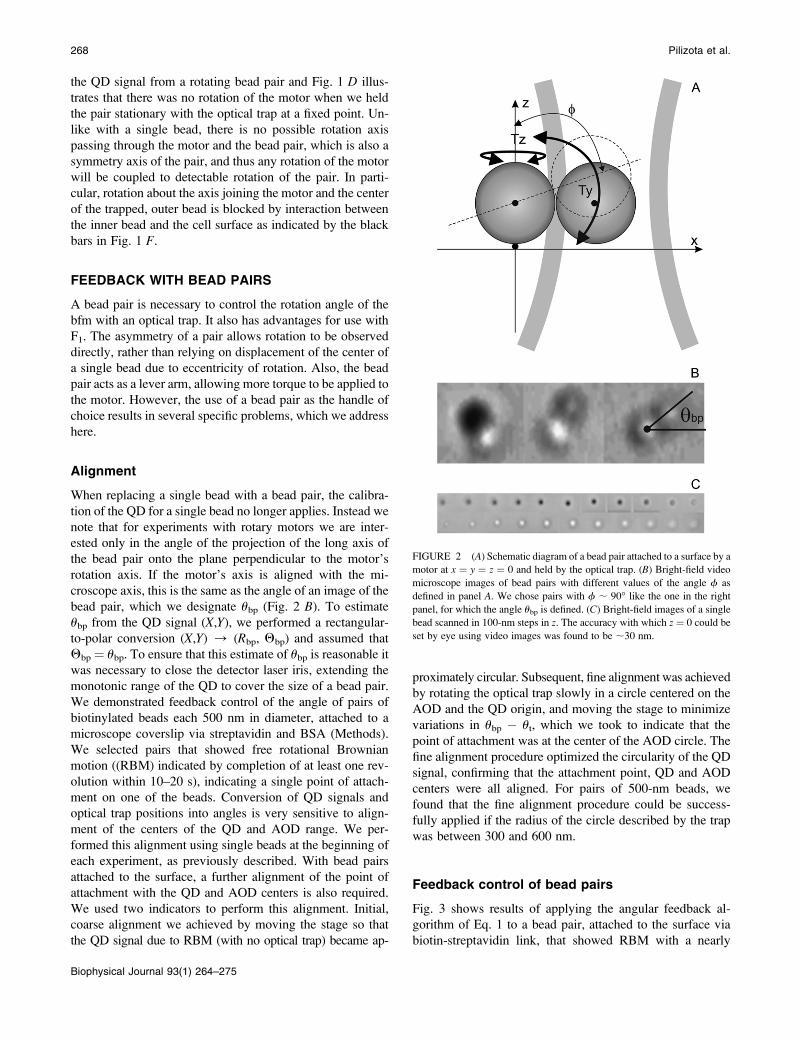
Alignment
When replacing a single bead with a bead pair, the calibra-
tion of the QD for a single bead no longer applies. Instead we
note that for experiments with rotary motors we are inter-
ested only in the angle of the projection of the long axis of
the bead pair onto the plane perpendicular to the motor’s
rotation axis. If the motor’s axis is aligned with the mi-
croscope axis, this is the same as the angle of an image of the
bead pair, which we designate ubp (Fig. 2 B). To estimate
ubp from the QD signal (X,Y), we performed a rectangular-
to-polar conversion (X,Y) / (Rbp, Qbp) and assumed that
Qbp ¼ ubp. To ensure that this estimate of ubp is reasonable it
was necessary to close the detector laser iris, extending the
monotonic range of the QD to cover the size of a bead pair.
We demonstrated feedback control of the angle of pairs of
biotinylated beads each 500 nm in diameter, attached to a
microscope coverslip via streptavidin and BSA (Methods).
We selected pairs that showed free rotational Brownian
motion ((RBM) indicated by completion of at least one rev-
olution within 10–20 s), indicating a single point of attach-
ment on one of the beads. Conversion of QD signals and
optical trap positions into angles is very sensitive to align-
ment of the centers of the QD and AOD range. We per-
formed this alignment using single beads at the beginning of
each experiment, as previously described. With bead pairs
attached to the surface, a further alignment of the point of
attachment with the QD and AOD centers is also required.
We used two indicators to perform this alignment. Initial,
coarse alignment we achieved by moving the stage so that
the QD signal due to RBM (with no optical trap) became ap-
proximately circular. Subsequent, fine alignment was achieved
by rotating the optical trap slowly in a circle centered on the
AOD and the QD origin, and moving the stage to minimize
variations in ubp � ut, which we took to indicate that the
point of attachment was at the center of the AOD circle. The
fine alignment procedure optimized the circularity of the QD
signal, confirming that the attachment point, QD and AOD
centers were all aligned. For pairs of 500-nm beads, we
found that the fine alignment procedure could be success-
fully applied if the radius of the circle described by the trap
was between 300 and 600 nm.
Feedback control of bead pairs
Fig. 3 shows results of applying the angular feedback al-
gorithm of Eq. 1 to a bead pair, attached to the surface via
biotin-streptavidin link, that showed RBM with a nearly
FIGURE 2 (A) Schematic diagram of a bead pair attached to a surface by a
motor at x ¼ y ¼ z ¼ 0 and held by the optical trap. (B) Bright-field video
microscope images of bead pairs with different values of the angle f as
defined in panel A. We chose pairs with f ; 90� like the one in the right
panel, for which the angle ubp is defined. (C) Bright-field images of a single
bead scanned in 100-nm steps in z. The accuracy with which z ¼ 0 could be
set by eye using video images was found to be ;30 nm.
268 Pilizota et al.
Biophysical Journal 93(1) 264–275
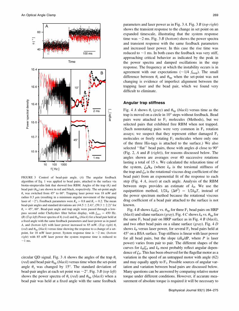
circular QD signal. Fig. 3 A shows the angles of the trap ut
(red) and bead pair ubp (black) versus time when the set-point
angle us was changed by 15�. The standard deviation of
bead-pair angles at each set point was ;2�. Fig. 3 B (top left)shows the power spectra of ut (red) and ubp (black) when a
bead pair was held at a fixed angle with the same feedback
parameters and laser power as in Fig. 3 A. Fig. 3 B (top right)shows the transient response to the change in set point on an
expanded timescale, illustrating that the system response
time was ;2 ms. Fig. 3 B (bottom) shows the power spectra
and transient response with the same feedback parameters
and increased laser power. In this case the rise time was
reduced to ;1 ms. In both cases the feedback was very stiff,
approaching critical behavior as indicated by the peak in
the power spectra and damped oscillations in the step
response. The frequency at which the instability occurs is in
agreement with our expectations (;1/4 floop). The small
difference between ut and ubp when the set-point was not
changing is evidence of imperfect alignment between the
trapping laser and the bead pair, which we found very
difficult to eliminate.
Angular trap stiffness
Fig. 4 A shows ut (gray) and ubp (black) versus time as the
trap is moved on a circle in 10� steps without feedback. Bead
pairs were attached to F1 molecules (Methods), but we
selected pairs that exhibited free RBM when not trapped.
(Such nonrotating pairs were very common in F1 rotation
assays; we suspect that they represent either damaged F1
molecules or freely rotating F1 molecules where only one
of the three His-tags is attached to the surface.) We also
selected ‘‘flat’’ bead pairs, those with angles f close to 90�(Fig. 2, A and B (right)), for reasons discussed below. The
angles shown are averages over 40 successive rotations
lasting a total of 15 s. We calculated the relaxation time of
the system, zu/ku (where ku is the torsional stiffness of
the trap and zu is the rotational viscous drag coefficient of the
bead pair) from an exponential fit of the response to each
step (Fig. 4 A, inset) at each angle. Analysis of the RBM
between steps provides an estimate of ku. We use the
equipartition method, 1/2ku ÆDu2æ ¼ 1/2kBT, instead of
the power spectrum method because the rotational viscous
drag coefficient of a bead pair attached to the surface is not
known.
Fig. 4 B shows ku/zu vs. ubp for three F1 bead pairs on HRP
(black) and silane surfaces (gray). Fig. 4 C shows ku vs. ubp for
the same F1 bead pair on HRP surface as in Fig. 4 B (black),
and two other bead pairs on a silane surface (gray). Fig. 4 Dshows ku versus laser power, for several F1 bead pairs held at
45� on a BSA surface. Trap stiffness is linear with laser power
for all bead pairs, but the slope (dku/dP, where P is laser
power) varies from pair to pair. The different shapes of the
curves for ku/zu and ku most probably reflect angular depen-
dence of zu. This has been observed for the flagellar motor as a
variation in the speed of an untrapped motor with angle (62)
and may equally apply to F1. Possible sources of angular var-
iation and variation between bead pairs are discussed below.
Many questions can be answered by comparing relative motor
torque under different conditions. However, if accurate mea-
surement of absolute torque is required it will be necessary to
FIGURE 3 Control of bead-pair angle. (A) The angular feedback
algorithm of Eq. 1 was applied to bead pairs, attached to the surface via
biotin-streptavidin link that showed free RBM. Angles of the trap (ut) and
bead pair (ubp) are shown in red and black, respectively. The set-point angle
us was switched from 45� to 60�. Trapping laser power was 18 mW and
radius 0.3 mm (resulting in a minimum angular movement of the trapping
laser of ;2�). Feedback parameters were Kp ¼ 0.8 and Ki ¼ 0.2. The mean
bead-pair angles and standard deviations are (44.5 6 2.4)�, (59.3 6 2.2)� for
us ¼ 45�, 60�. Bead-pair angle and trap angle were passed through a low-
pass second order Chebyshev filter before display, with fpass ¼ 450 Hz.
(B) (Top left) Power spectra of ut (red) and ubp (black) for a bead pair held at
a fixed angle with the same feedback parameters and laser power as in panel
A, and (bottom left) with laser power increased to 85 mW. (Top right) ut
(red) and ubp (black) versus time showing the response to a change of a set-
point, for 18 mW laser power. System response time is ;2 ms; (bottom
right) with 85 mW laser power the system response time is reduced to
;1 ms.
An Optical Angle Clamp 269
Biophysical Journal 93(1) 264–275

calibrate the angular trap stiffness for each bead pair after
inactivating the motor at the end of each experiment. We have
developed and presented here a calibration procedure that can
be completed in a few seconds and implemented as part of the
experimental protocol.
Preliminary experiments with rotarymolecular motors
In this section we describe preliminary experiments in which
we demonstrate the application of our system to single-
molecule assays of rotary molecular motors.
Fig. 5 A shows control of the angle of a 500-nm bead pair
attached to the rotating g-subunit of F1 (Methods, (23)),
using the feedback algorithm of Eq. 1. The angles of the bead
pair, ubp, and trap, ut, are shown in black and gray, re-
spectively. After ;5 revolutions with the trap shuttered and
the motor rotating freely, the shutter is opened and the motor
stalled by a fixed trap at ut ¼ 90�. Approximately 0.5 s later
feedback is switched on for ;2 s, with a set-point of ubp ¼90�, and then switched off again, leaving the trap at ut¼ 90�.
Finally, the trap is shuttered and the motor starts rotating as
before. This was repeated eight times for the bead shown and
for 12 different bead pairs attached to F1 (data not shown).
We did not calibrate this particular bead pair, so we cannot
give an accurate estimate of the stall torque. If we estimate
the trap stiffness from the signal of the stalled motor without
feedback by using the Principle of Equipartition of Energy,
we have ku ¼ 438 6 116 pN nm rad�2 and a stall torque of
Tstall ¼ ku Æ ubp �ut æ ¼ 74 6 20 pN nm. This is higher than
the values of 40 pN nm and 63 pN nm estimated by other
methods (23,25), perhaps because the stiffness of the intact
F1 adds to the trap stiffness leading to an overestimate of the
latter. This preliminary experiment demonstrates that we can
control the angle of F1 with high accuracy and time resolu-
tion, and that the procedure does not appear to damage the
motor.
Fig. 5 B shows control of the angle of a 500-nm bead pair
attached to the bfm using the same methods as described for
Fig. 5 A. We applied feedback with different set angles
during periods lasting 3 s or 10 s, alternated with periods of
the same length when we allowed the motor to rotate freely,
providing an independent measure of the motor torque and
to determine whether any damage had occurred (data not
shown). Fig. 5 B shows ubp (black) and ut (gray) for the
periods when feedback was on and the set angle was 90�.
Assuming that the trap torque is proportional to ut � ubp, we
interpret the data of Fig. 5 B as changes in the motor torque
from 2 to 1 times a unitary torque, and then to 0. The ob-
served halving of the motor torque (Fig. 5 B, middle) most
probably corresponds to a change from two torque generating
units to one, similar to speed changes seen previously in
freely rotating motors (18,27). We did not calibrate this
particular bead pair, however, we subsequently subjected
five other cells to the protocol of Fig. 5 B. A histogram of the
freely rotating speeds recorded from those five cells showed
peaks corresponding to different numbers of stator units
((27), Supplementary Fig. S1 B, see Supplementary Material).
FIGURE 4 Calibration of the angular
trap stiffness for 500-nm nonrotating
bead pairs attached to F1 molecules. (A)
Bead-pair angle, ubp (black), and trap
angle, ut (gray), versus time for a bead
pair in a trap moving in 10� steps
without feedback. Angles are averages
over 40 successive rotations. (Inset)
Step-response, with exponential fit. (B)
The ratio of angular trap stiffness to
rotational viscous drag coefficient, de-
rived from the time constants in the fits
in panel A as described in the text, versus
angle, for three bead pairs on HRP
surface (black) and silane surface (gray)
(Methods). (C) Angular trap stiffness
versus angle for the same bead pair as in
panel B (black) and two additional bead
pairs (gray) on silane surface. (D) Trap
stiffness using at 45� versus laser power
for several bead pairs on a BSA surface
(Methods). Data were sampled at 10
kHz, laser power in panels A–D was
30 mW, and the trap was kept on
0.42 mm radius circle. Bead pairs with
f ; 90�, which performed free rota-
tional Brownian motion without the trap were chosen for all calibration experiments. Error bars in B and C are standard errors obtained by averaging values of ratio
of angular trap stiffness to rotational viscous drag coefficient and angular trap stiffness of two adjacent angles.
270 Pilizota et al.
Biophysical Journal 93(1) 264–275

This allowed us to estimate the speed of a 500-nm bead pair
driven by a single unit as 10.7 6 3.3 Hz. Calibration of three
of the five bead pairs used in these experiments allowed us
to estimate the stall torque of the motors immediately be-
fore and after each free-running period (in total 35 torque
measurements, Supplementary Fig. S1 A). We found that the
stall torques were proportional to free running speed.
Assuming that the torque changes very little between stall
and the maximum free running speed of ;100 Hz (28,63) we
estimated the average viscous drag coefficient of the bead
pair, z, to be 17 6 2 pN nm Hz�1, and the torque per stator
unit to be 170 6 40 pN nm in agreement with previous
estimates (27).
Fig. 5 C shows the QD signal (inset, upper) and speeds of
a bead pair attached to a bacterial flagellar motor, made to
rotate at speeds up to 425 Hz by moving the trapping laser
in a circle at a constant speed without feedback. As in the
feedback experiment, above, we allowed the motors to rotate
freely between periods of forced rotation to determine
whether any damage had occurred. Speeds measured when
the motor was under control of the trap are shown in black,
and speeds of freely rotating motors are in gray. We stopped
the experiment when rotation of the free motor was no longer
observed.
DISCUSSION
In this article we present an optical trapping system designed
for the study of rotary molecular motors. A host computer
and DSP board are integral parts of the system allowing soft-
ware control of feedback algorithms and time resolutions of
milliseconds. We present several feedback algorithms. The
two-dimensional X and Y feedback algorithm gives essentially
the same control of the trapping laser as used for studies of
linear molecular motors, whereas the one-dimensional angular
algorithm (Eq. 1) is more suitable for control of rotary motors,
in particular in combination with the use of bead pairs as a
handle for applying torque to rotary molecular motors. In pre-
vious studies of linear molecular motors, independent x and
y feedback control was implemented either in software (51)
or by analog proportional-integral-derivative circuits (64).
The spatial resolution achieved in those studies was higher
FIGURE 5 (A) Bead-pair angle, ubp (black), and trap angle, ut (gray), for a
500-nm bead pair attached to the rotating g-subunit of F1. The bead pair
rotated at the beginning and end of the record when the trap was shuttered.
The feedback algorithm of Eq. 1 was used to hold ubp¼ 90� in the middle of
the record. At other times, the bead pair was held in the trap with no
feedback. Feedback parameters Kp¼ 0.8 and Ki¼ 0.2, radius of the trapping
laser ¼ 480 nm, laser power ¼ 31 mW. (B) ubp (black) and ut, (gray) for a
500-nm bead pair attached to the bfm with the feedback algorithm of Eq. 4
used to hold ubp ¼ 90�. The difference between trap angle and bead-pair
angle corresponds to the bacterial flagellar motor torque. We interpret the
data as showing a motor initially with two stator units losing first one and
later both units, such that the torque goes from 2/1/0 times the torque of
a single unit. Feedback parameters Kp ¼ 0.8 and Ki ¼ 0.1, radius of the
trapping laser¼ 0.42 mm, laser power¼ 29 mW. (C) Control of the speed of
the bfm using a 500-nm bead pair and the optical trap without feedback. ubp
followed the trapping laser, which was rotated at different speeds up to 425
Hz (black). At regular intervals the trap was shuttered and the bead pair
allowed to rotate freely (gray, expanded in lower inset). The stepwise
reduction in freely rotating speed indicates a reduction in the number of
torque-generating units in the order 3, 2, 1, 0. (Inset, upper) The QD X and Y
signals for the rotating bead pair at different speeds. The trap radius was
changed between 0.6 and 0.3 mm during the experiment and the laser power
was 65 mW.
An Optical Angle Clamp 271
Biophysical Journal 93(1) 264–275
than presented in this article, usually on the order of 1 nm,
however, the 9-nm resolution of our AODs is adequate for
the 1–10� angular resolution required for rotary molecular
motors studies. The time resolution of our system is on the
order of 1–2 ms, suitable for studies of F1 and the bfm.
Analog proportional-integral-derivative circuits for trapping
laser control can offer higher time resolution, but lack the
flexibility to implement various nonlinear algorithms and
have therefore not been used in the system presented in this
article. The control of our system is precisely clocked due to
the use of a fast DSP, unlike in feedback systems imple-
mented in software on the host computer. Faster DSP boards
and AODs with faster response time are commercially
available and would offer improved time and angle resolu-
tion if required.
Previous studies have used magnetic tweezers (29–31) and
electrorotation (28,63) to apply torque to rotary molecular
motors. Here we have explored the possibility of using
optical tweezers and have addressed the technical difficulties
of this method. The temporal and angular resolutions achieved
here are improved compared to both magnetic tweezers and
electrorotation. Calibration of the torque exerted by optical
tweezers is in principle easier than that of the other tech-
niques due to the greater reproducibility of the bead-pair
handles compared to magnetic beads or tethered cell bodies.
However, we have found considerable variation in the trap
stiffness when holding bead pairs, which may require calibra-
tion for each bead pair studied in the future. A further ad-
vantage over electrorotation is that the technique places no
special requirements on the conductivity of the medium, for
example, allowing experiments in the relatively high ionic
strengths that are suitable for study of sodium-driven fla-
gellar motors (17).
There are several reasons why a bead pair serves as a
better handle for micromanipulation with an optical trap
than a single bead. Most obviously, the asymmetry of a
bead pair indicates motor rotation more clearly than a single
bead, which can rotate about any diameter without being
detected by a position-sensitive detector. The extended lever
arm of a bead pair increases the linear motion for a given
angular motion, which enhances both the sensitivity of
angular detection and the amount of torque that can be
applied using a conventional optical trap. Furthermore, we
have observed that a single 500-nm bead cannot be optically
trapped to control the angle of the flagellar motor, due to
the flagellar hook acting as a universal joint. Rotating bead
pairs attached to the flagellar motor sometimes produced
highly elliptical traces (data not shown), indicating either
misalignment of the center of rotation with the QD,
misalignment of the rotation axis with the microscope
axis, or extra degrees of freedom. Rotating bead pairs at-
tached to F1 produce almost circular trajectories. For high-
precision measurements of both rotary molecular motors it
will be necessary to select motors with nearly circular
trajectories.
The torque exerted on a motor via a bead pair in a linearly
polarized optical trap can be written as Ttrap¼ Tlever 1 Tshape 1
Tpolarization, where Tlever is the combined effect of the linear
force on the bead pair and the reaction force at the motor,
Tshape is the alignment effect of a nonspherical trap on a
nonspherical particle, and Tpolarization is a torque acting to
align the long axis of the bead pair with the polarization vector
of the laser beam. Referring to Fig. 2 A to define x, y, and zaxes, we can expect Tshape ¼ (0, Ty,shape, 0), as single-beam
optical traps are typically extended in the z-direction and
particles align with their long axes parallel to the optical axis
of the trap (41–43), and Tlever¼ (0, 0,�klever(ubp� ut)). When
a bead pair attached to a molecular motor is held in feedback,
the trap torque will balance the torque due to the bead-motor-
surface link: Ttrap ¼ Tlink. Considering the z-components we
have
Tz;link ¼ �kleverðubp � utÞ1 Tz;polarization ¼ �kuðubp � utÞ: (2)
In an ideal system, Tz,link would be dominated by the mo-
tor torque that we are trying to investigate, klever would be
constant, and Tz,polarization would be negligible, in which case
ku would also be a constant. In this case we would have
Tmotor ¼ �kuðubp � utÞ ¼ �kleverðubp � utÞ: (3)
In practice, however, Tz,link and ku may vary with ubp for
the following reasons: 1), klever will vary with angle due to
variations in laser intensity at different trap positions,
differences between trap stiffness in x and y, and misalign-
ment of each bead pair leading to different lengths of
lever arm at different angles. 2), Whereas intuitively we
might expect Tz,polarization to have a period of 180� in ubp,
theoretical predictions show that higher periodicities might
be possible depending on the shape and size of the particle
(65). 3), Other than Tmotor the most likely contributor to
Tz,link is direct interaction between the bead pair and the
surface, in parallel with the linkage via the motor. The
angular dependence of this interaction is impossible to
predict, may vary from bead to bead, and furthermore may
depend upon Ty. Minimizing Ty by selecting flat-rotating
‘‘propeller’’ bead pairs (as discussed below) is expected to
minimize this effect, and the observation of bead pairs
performing free RBM indicates that Tz,link is negligible for
many bead pairs in the absence of any trap torque.
Regardless of the exact causes of angular variation in the
trap torque, our measurements indicate that variation is
considerable and not predictable, and that trap stiffness must
be calibrated for each bead pair if absolute torques are to be
measured.
There are two reasons to minimize the alignment torque,
Ty. As well as the possible effect on Tz,link, as discussed
above, Ty will be balanced by an opposing torque that
consists of a vertical force acting on the motor multiplied by
the lever-arm distance between the motor and a second point
272 Pilizota et al.
Biophysical Journal 93(1) 264–275

of contact between the bead and surface. The lever arm is
likely to be very short, on the order of the size of the motor,
and thus the force on the motor may be large even for
relatively small Ty. Ty consists of Ty,shape and Ty,polarization,
both of which depend upon the angle, f (Fig. 2 A). As this
angle increases, bead pairs change from vertically stacked
beads, f ¼ 0�, to flat-rotating propellers, f ¼ 90�, whereas
the radius of the circle described by the center of the outer
bead increases from zero to the bead diameter (Fig. 2 B). At
f ¼ 90� Ty is equal to zero (42,65,66), which is the reason
for choosing flat-rotating propellers in our experiments. For
bead pairs attached to the bfm or F1, these are common. The
height of a single 500-nm bead can be judged by eye with an
accuracy of ;30 nm, corresponding to ;3� in f. The
accuracy in determining f may be improved since we are
comparing the image of the two adjacent beads (Fig. 2 B).
Others have estimated Ty ¼ ;300 pNnm at f ¼ 87� for
chloroplasts of radius 500 nm and length 2 mm (in a 1064-nm
laser trap at 30 mW laser power (42)). Thus we might expect
Ty on the order of tens of pNnm in our experiments. As well
as the vertical force opposing Ty and the lateral force com-
pleting the couple Tlever, the motor may experience a radial
force pulling the bead pair toward the center of the trap. In
our experiments, the trap moves at a radius similar to the
bead diameter, and therefore we expect small radial force,
but whatever the actual values of the vertical and horizontal
forces on the motor, the immediate resumption of spinning
when the trap is shuttered illustrated in Fig. 5 A demonstrates
that they are small enough not to damage F1.
By contrast, our preliminary experiments on the bacterial
flagellar motor indicate that damage to motors may be an
important practical consideration when using the optical trap
to investigate the motor. Laser exposure in the experiments
illustrated in Fig. 5, A–C, was minimal, and is not expected
to cause significant photodamage (54). The reductions in
motor torque observed are therefore probably attributable
to mechanical damage that inactivates individual torque-
generating units, as seen in previous experiments in which
electrorotation was used to apply external torque to the
flagellar motor (63). For most of the cells we observed, sig-
nificant damage occurred during the fine alignment proce-
dure, indicated by a reduction in the speed of the free motor.
The time it takes for fine alignment varies from cell to cell,
but it is usually on the order of 1 min. In cases where
the trajectory of the bead pair attached to the motor was
almost circular the fine alignment procedure may not be
necessary and might be omitted in the future. If the problem
of mechanical damage can be solved it will be possible to
determine the motor torque at each speed using Eq. 2,
calibrating ku(ubp) for each bead pair. If so, the method
of Fig. 5 C will allow measurement of the torque-speed
relationship of the bfm under a wide range of different
conditions, especially when the motor is driven backward or
forward up to and beyond the zero torque speed, regimes
that are not accessible without the application of external
torque.
SUPPLEMENTARY MATERIAL
An online supplement to this article can be found by visiting
BJ Online at http://www.biophysj.org.
We thank Simon Ross, Jelena Baranovic, and Maja Petkovic for help with
purification of F1-ATPase and Norman Heckenberg for critical reading of
the manuscript.
The research of T.P and R.B. was supported by the combined United
Kingdom Research Councils via an Interdisciplinary Research Collabora-
tion in Bionanotechnology and the European Union, that of F.B. by a
Clarendon Scholarship, and that of T.B. by the Engineering and Physical
Sciences Research Council via the Doctoral Training Centre at the Life
Sciences Interface.
REFERENCES
1. Ashkin, A. 1970. Acceleration and trapping of particles by radiationpressure. Phy. Rev. Lett. 24:156–159.
2. Ashkin, A., and J. M. Dziedzic. 1971. Optical levitation by radiationpressure. Appl. Phys. Lett. 19:283–285.
3. Ashkin, A., J. M. Dziedzic, J. E. Bjorkholm, and S. Chu. 1986.Observation of a single-beam gradient force optical trap for dielectricparticles. Opt. Lett. 11:288–290.
4. Ashkin, A. 2000. History of optical trapping and manipulation ofsmall-neutral particles, atoms, and molecules. IEEE J. Sel. Top.Quantum Electron. 6:841–856.
5. Chu, S., J. E. Bjorkholm, A. Ashkin, and A. Cable. 1986. Experi-mental observation of optically trapped atoms. Phys. Rev. Lett. 57:314–317.
6. Ashkin, A., J. M. Dziedzic, and T. Yamane. 1987. Optical trapping andmanipulation of single cells using infrared laser beams. Nature. 330:769–771.
7. Ashkin, A., and J. M. Dziedzic. 1987. Optical trapping and manip-ulation of viruses and bacteria. Science. 235:1517–1520.
8. Mehta, A. D., M. Rief, J. A. Spudich, D. A. Smith, and R. M. Simmons.1999. Single-molecule biomechanics with optical methods. Science.283:1689–1695.
9. Svoboda, K., and S. M. Block. 1994. Biological applications of opticalforces. Annu. Rev. Biophys. Biomol. Struct. 23:247–285.
10. Mehta, A. D., R. S. Rock, M. Rief, J. A. Spudich, M. S. Mooseker, andR. E. Cheney. 1999. Myosin-V is a processive actin-based motor.Nature. 400:590–593.
11. Svoboda, K., C. F. Schmidt, B. J. Schnapp, and S. M. Block. 1993.Direct observation of kinesin stepping by optical interferometry. Na-ture. 365:721–727.
12. Mallik, R., B. C. Carter, S. A. Lex, S. J. King, and S. P. Gross. 2004.Cytoplasmic dynein functions as a gear in response to load. Nature.427:649–652.
13. Wang, M. D., H. Yin, R. Landick, J. Gelles, and S. M. Block. 1997.Stretching DNA with optical tweezers. Biophys. J. 72:1335–1346.
14. Visscher, K., M. J. Schnitzer, and S. M. Block. 1999. Singlekinesin molecules studied with a molecular force clamp. Nature.400:184–189.
15. Berry, R. M., and J. P. Armitage. 1999. The bacterial flagella motor.Adv. Microb. Physiol. 41:291–337.
16. Berg, H. C. 2003. The rotary motor of bacterial flagella. Annu. Rev.Biochem. 72:19–54.
An Optical Angle Clamp 273
Biophysical Journal 93(1) 264–275

17. Sowa, Y., A. D. Rowe, M. C. Leake, T. Yakushi, M. Homma,A. Ishijima, and R. M. Berry. 2005. Direct observation of steps inrotation of the bacterial flagellar motor. Nature. 437:916–919.
18. Ryu, W. S., R. M. Berry, and H. C. Berg. 2000. Torque-generatingunits of the flagellar motor of Escherichia coli have a high duty ratio.Nature. 403:444–447.
19. Yoshida, M., E. Muneyuki, and T. Hisabori. 2001. ATP synthase-Amarvellous rotary engine of the cell. Nat. Rev. Mol. Cell Biol. 2:667–677.
20. Boyer, P. D. 1997. The ATP synthase—a splendid molecular machine.Annu. Rev. Biochem. 66:717–749.
21. Stock, D., A. G. Leslie, and J. E. Walker. 1999. Molecular archi-tecture of the rotary motor in ATP synthase. Science. 286:1687–1688.
22. Noji, H., R. Yasuda, M. Yoshida, and K. Kinosita Jr. 1997. Directobservation of the rotation of F1-ATPase. Nature. 386:217–219.
23. Yasuda, R., H. Noji, M. Yoshida, K. Kinosita Jr., and H. Itoh. 2001.Resolution of distinct rotational substeps by submillisecond kineticanalysis of F1-ATPase. Nature. 410:898–904.
24. Nishizaka, T., K. Oiwa, H. Noji, S. Kimura, E. Muneyuki, M. Yoshida,and K. Kinosita Jr. 2004. Chemomechanical coupling in F1-ATPaserevealed by simultaneous observation of nucleotide kinetics and rotation.Nat. Struct. Mol. Biol. 11:110–112.
25. Spetzler, D., J. York, D. Daniel, R. Fromme, D. Lowry, and W. Frasch.2006. Microsecond time scale rotation measurements of singleF1-ATPase molecules. Biochemistry. 45:3117–3124.
26. Nakanishi-Matsui, M., S. Kashiwagi, H. Hosokawa, D. J. Cipriano,S. D. Dunn, Y. Wada, and M. Futai. 2006. Stochastic high-speedrotation of Escherichia coli ATP synthase F1 sector: the e subunit sen-sitive rotation. J. Biol. Chem. 281:4126–4131.
27. Reid, S. W., M. C. Leake, J. H. Chandler, C.-J. Lo, J. P. Armitage, andR. M. Berry. 2006. The maximum number of torque generating units inthe flagellar motor of Escherichia coli is at least 11. Proc. Natl. Acad.Sci. USA.103:8066–8071.
28. Berg, H. C., and L. Turner. 1993. Torque generated by the flagellarmotor of Escherichia coli. Biophys. J. 65:2201–2216.
29. Itoh, H., A. Takahashi, A. Adachi, H. Noji, R. Yasuda, M. Yoshida, andK. Kinosita. 2004. Mechanically driven ATP synthesis by F1-ATPase.Nature. 427:465–468.
30. Rondelez, Y., G. Tresser, T. Nakashima, Y. Kato-Yamada, H. Fujita,S. Takeuchi, and H. Noji. 2005. Highly coupled ATP synthesis byF1-ATPase single molecules. Nature. 433:773–777.
31. Hirono-Hara, Y., K. Ishizuka, K. Kinosita Jr., M. Yoshida, and H. Noji.2005. Activation of pausing F1 motor by external force. Proc. Natl.Acad. Sci. USA. 102:4288–4293.
32. Berry, R. M., and H. C. Berg. 1997. Absence of a barrier to backwardsrotation of the bacterial flagellar motor demonstrated with opticaltweezers. Proc. Natl. Acad. Sci. USA. 94:14422–14427.
33. Block, S. M., D. F. Blair, and H. C. Berg. 1991. Compliance ofbacterial polyhooks measured with optical tweezers. Cytometry.12:492–496.
34. Block, S. M., D. F. Blair, and H. C. Berg. 1989. Compliance ofbacterial flagella measured with optical tweezers. Nature. 338:514–518.
35. Nieminen, T. A., N. R. Heckenberg, and H. Rubinsztein-Dunlop.2001. Optical measurement of microscopic torques. J. Mod. Optic. 48:405–413.
36. Friese, M. E. J., T. A. Nieminen, N. R. Heckenberg, and H. Rubinsztein-Dunlop. 1998. Optical alignment and spinning of laser-trapped micro-scopic particles. Nature. 394:348–350.
37. Higurashi, E., R. Sawada, and T. Ito. 1999. Optically induced angularalignment of trapped birefringent micro-objects by linearly polarizedlight. Phys. Rev. E. 59:3676–3681.
38. Singer, W., T. A. Nieminen, U. J. Gibson, N. R. Heckenberg, andH. Rubinsztein-Dunlop. 2006. Orientation of optically trapped non-spherical birefringent particles. Phys. Rev. E. 73:021911.
39. Bishop, A. I., T. A. Nieminen, N. R. Heckenberg, and H. Rubinsztein-Dunlop. 2004. Optical microrheology using rotating laser-trappedparticles. Phys. Rev. Lett. 92:198104.
40. Porta, A. L., and M. Wang. 2004. Optical torque wrench: angulartrapping, rotation and torque detection of quartz microparticles. Phys.Rev. Lett. 92:190801.
41. Bishop, A.I., T.A. Nieminen, and N.R. Heckenberg. 2003. Opticalapplication and measurement of torque on microparticles of isotropicnonabsorbing material. Phys. Rev. A. 68:033802.
42. Bayoudh, S., T. A. Nieminen, and N. R. Heckenberg. 2003. Orien-tation of biological cells using plane-polarized Gaussian beam opticaltweezers. J. Mod. Optic. 50:1581–1590.
43. Gauthier, R. C., M. Ashman, and C. P. Grover. 1999. Experimentalconfirmation of the optical-trapping properties of cylindrical objects.Appl. Opt. 38:4861–4869.
44. Friese, M. E. J., J. Enger, H. Rubinsztein-Dunlop, and N. R. Heckenberg.1996. Optical angular-momentum transfer of trapped absorbing particles.Phys. Rev. A. 54:1593–1596.
45. Rubinsztein-Dunlop, H., T. A. Nieminen, M. E. J. Friese, and N. R.Heckenberg. 1998. Optical trapping of absorbing particles. Adv. Quan-tum. Chem. 30:469–492.
46. Paterson, L., M. P. MacDonald, J. Arlt, W. Sibbett, P. E. Bryant, andK. Dholakia. 2001. Controlled rotation of optically trapped micro-scopic particles. Science. 292:912–914.
47. Sato, S., M. Ishigure, and H. Inaba. 1991. Optical trapping and rota-tional manipulation of microscopic particles and biological cells us-ing higher-order mode Nd:YAG laser beams. Electron. Lett. 27:1831–1832.
48. Santamato, E., A. Sasso, B. Piccirillo, and A. Vella. 2002. Opticalangular momentum transfer to transparent isotropic particles using laserbeam carrying zero average angular momentum. Opt. Express. 10:871–878.
49. O’Neil, A. T., and M. J. Padgett. 2002. Rotational control withinoptical tweezers by use of a rotating aperture. Opt. Lett. 27:743–745.
50. Galajda, P., and P. Ormos. 2001. Complex micromachines producedand driven by light. Appl. Phys. Lett. 78:249–251.
51. Lang, M. J., C. L. Asbury, J. W. Shaevitz, and S. M. Block. 2002. Anautomated two-dimensional optical force clamp for single moleculestudies. Biophys. J. 83:491–501.
52. Neuman, K. C., and S. M. Block. 2004. Optical trapping. Rev. Sci.Instrum. 75:2787–2809.
53. Sorensen, K. B., and H. Flyvbjerg. 2004. Power spectrum analysis foroptical tweezers. Rev. Sci. Instrum. 75:594–612.
54. Neuman, K.C., E. H. Chadd, G. F. Liou, K. Bergman, and S. M. Block.1999. Characterization of photodamage to Escherichia coli in opticaltraps. Biophys. J. 77:2856–2863.
55. Peterman, E. J. G., A. van Dijk Meindert, L. C. Kapitein, and C. F.Schmidt. 2003. Extending the bandwidth of optical-tweezers interfer-ometry. Rev. Sci. Instrum. 74:3246–3249.
56. Berg-Sorensen, K., and L. Oddershede. 2003. Unintended filtering in atypical photodiode detection system for optical tweezers. J. Appl. Phys.93:3167–3176.
57. Tolic-Norrleykke, I. M., K. Berg-Sorensen, and H. Flyvbjerg. 2004.MatLab program for precision calibration of optical tweezers. Comp.Phys. Comm. 159:225–240.
58. Bechhoefer, J. 2005. Feedback for physicists: a tutorial essay on con-trol. Rev. Mod. Phys. 77:783–836.
59. Omote, H., N. Sambonmatsu, K. Saito, Y. Sambongi, A. Iwamoto-Kihara, Y. Yanagida, Y. Wada, Y., and M. Futai. 1999. The g-subunitrotation and torque generation in F1-ATPase from wild-type or un-coupled mutant Escherichia coli. 1999. Proc. Natl. Acad. Sci. USA.96:7780–7784.
60. Iko, Y., Y. Sambongi, M. Tanabe, A. Iwamoto-Kihara, K. Saito,I. Ueda, Y. Wada, and M. Futai. 2001. ATP Synthase F1 sectorrotation. J. Biol. Chem. 276:47508–47511.
274 Pilizota et al.
Biophysical Journal 93(1) 264–275

61. Sakaki, N., R. Shimo-Kon, K. Adachi, H. Itoh, S. Furuike, E. Muneyuki,M. Yoshida, and K. Kinosita. 2005. One rotary mechanism forF1-ATPase over ATP concentrations from millimolar down to nano-molar. Biophys. J. 88:2047–2056.
62. Berry, R. M., and H. C. Berg. 1996. Torque generated by the bacterialflagellar motor close to stall. Biophys. J. 71:3501–3510.
63. Berry, R. M., L. Turner, and H. C. Berg. 1995. Mechanical limits of bac-terial flagellar motors probed by electrorotation. Biophys. J. 69:280–286.
64. Simmons, R. M., J. T. Finer, S. Chu, and J. A. Spudich. 1996. Quan-titative measurements of force and displacement using an optical trap.Biophys. J. 70:1813–1822.
65. Rockstuhl, C., and H. P. Herzig. 2005. Calculation of the torque ondielectric elliptical cylinders. J. Opt. Soc. Am. A. 22:109–116.
66. Gauthier, R. C. 1997. Theoretical investigation of the optical trappingforce and torque on cylindrical micro-objects. J. Opt. Soc. Am. B. 14:3323–3333.
An Optical Angle Clamp 275
Biophysical Journal 93(1) 264–275