
A Process for Reducing Rocks and Concentrating … Process for Reducing Rocks and Concentrating...
24
U.S. Department of the Interior U.S. Geological Survey Open-File Report 2016–1022 A Process for Reducing Rocks and Concentrating Heavy Minerals
Transcript of A Process for Reducing Rocks and Concentrating … Process for Reducing Rocks and Concentrating...

U.S. Department of the InteriorU.S. Geological Survey
Open-File Report 2016–1022
A Process for Reducing Rocks and Concentrating Heavy Minerals

Cover. Top, Temora 2 standard—zircon separated from whole rock with in situ inclusions. Bottom, Temora 2 zircon standard—zircon and zircon fragments separated from whole rock. Black grains are liberated inclusion minerals. Photographs by Thomas R. Strong, U.S. Geological Survey.

A Process for Reducing Rocks and Concentrating Heavy Minerals
By Thomas R. Strong and Rhonda L. Driscoll
Open-File Report 2016–1022
U.S. Department of the InteriorU.S. Geological Survey

U.S. Department of the InteriorSALLY JEWELL, Secretary
U.S. Geological SurveySuzette M. Kimball, Director
U.S. Geological Survey, Reston, Virginia: 2016
For more information on the USGS—the Federal source for science about the Earth, its natural and living resources, natural hazards, and the environment—visit http://www.usgs.gov or call 1–888–ASK–USGS.
For an overview of USGS information products, including maps, imagery, and publications, visit http://www.usgs.gov/pubprod/.
Any use of trade, firm, or product names is for descriptive purposes only and does not imply endorsement by the U.S. Government.
Although this information product, for the most part, is in the public domain, it also may contain copyrighted materials as noted in the text. Permission to reproduce copyrighted items must be secured from the copyright owner.
Suggested citation:Strong, T.R., and Driscoll, R.L., 2016, A process for reducing rocks and concentrating heavy minerals: U.S. Geological Survey Open-File Report 2016–1022, 16 p., http://dx.doi.org/10.3133/ofr20161022.
ISSN 2331-1258 (online)

iii
Contents
Abstract ...........................................................................................................................................................1Introduction.....................................................................................................................................................1Preparation for Rock Reduction ..................................................................................................................1Sturtevant Jaw Crusher General Information ...........................................................................................2Sturtevant Jaw Crusher Setup ....................................................................................................................2Sturtevant Jaw Crusher Procedure ............................................................................................................2Bico-Braun Vertical Disk Grinder-Pulverizer General Information .......................................................3Bico-Braun Vertical Disk Grinder-Pulverizer Setup .................................................................................3Bico-Braun Vertical Disk Grinder-Pulverizer Procedure ........................................................................3Tyler Ro-Tap Test Sieve Shaker General Information ..............................................................................4Tyler Ro-Tap Test Sieve Shaker Setup........................................................................................................5Tyler Ro-Tap Test Sieve Shaker Procedure ...............................................................................................5Wilfley Table General Information ..............................................................................................................6Wilfley Table Setup ........................................................................................................................................7Wilfley Table Procedure ...............................................................................................................................8Frantz Magnetic Separation ........................................................................................................................9Frantz Magnetic Separation General Introduction ..................................................................................9Frantz Magnetic Separator Setup .............................................................................................................10Frantz Magnetic Separator Procedure ....................................................................................................10Heavy Liquids General Information ..........................................................................................................11Heavy Liquids Separation Setup ...............................................................................................................13Heavy Liquid Separation Procedure .........................................................................................................14Conclusion.....................................................................................................................................................15References Cited..........................................................................................................................................16
Figures 1–5. Photographs of: 1. Operator prepares to drop a cobble between the crushing “jaws” .............................3 2. Disk grinder opened to expose manganese grinding disks ...........................................4 3. Disk grinder adjustment assembly showing the thread handle and
end lock knob .........................................................................................................................4 4. The sieve shaker showing a mounted sieve stack and hammer-like arm ...................5 5. Sieved material poured from specific sieves onto white paper ....................................6 6. Diagram showing Wilfley Table detail .......................................................................................7 7. Photograph of the sample as it passes under the magnet before dropping to the
riffled surface ................................................................................................................................8 8. Photograph of Wilfley Table water flow and plume separation ...........................................9 9–11. Diagrams showing:
9. K-L-M-N orbital shells and electron distribution and configuration for five elements ................................................................................................................10
10. The silicon electron configuration ..................................................................................11 11. An unpaired electron spinning within an orbit .............................................................11
iv
12–14. Photographs of: 12. The Frantz Magnetic Separator with vibration controllers, glass
hopper, sample discharge, and two-channel track for paramagnetic and nonmagnetic division ................................................................................................12
13. The heavy liquids separation set up ...............................................................................14 14. The separatory funnel stem inside the filtered funnel to prevent splash .................15
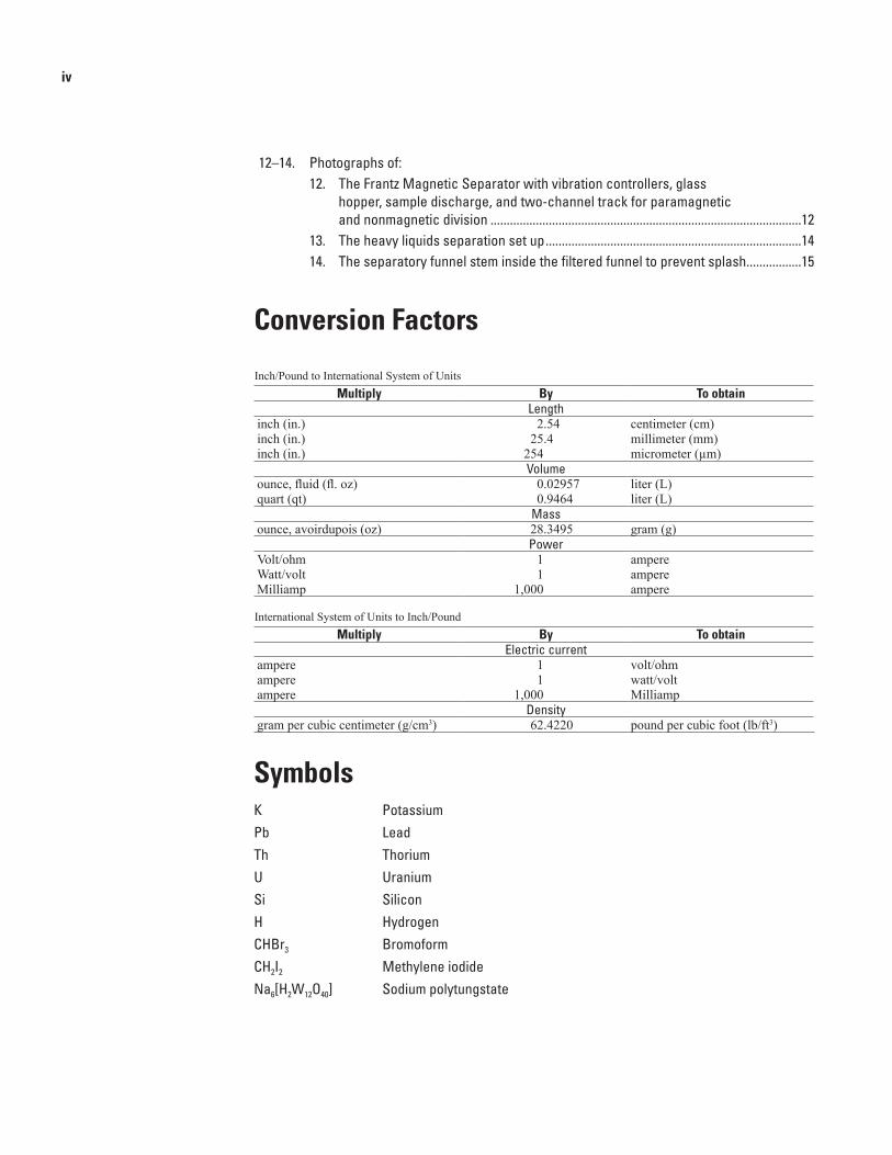
Conversion Factors
Inch/Pound to International System of UnitsMultiply By To obtain
Lengthinch (in.) 2.54 centimeter (cm)inch (in.) 25.4 millimeter (mm)inch (in.) 254 micrometer (µm)
Volumeounce, fluid (fl. oz) 0.02957 liter (L) quart (qt) 0.9464 liter (L)
Massounce, avoirdupois (oz) 28.3495 gram (g)
PowerVolt/ohm 1 ampere Watt/volt 1 ampere Milliamp 1,000 ampere
International System of Units to Inch/PoundMultiply By To obtain
Electric currentampere 1 volt/ohmampere 1 watt/voltampere 1,000 Milliamp
Densitygram per cubic centimeter (g/cm3) 62.4220 pound per cubic foot (lb/ft3)
SymbolsK PotassiumPb LeadTh ThoriumU UraniumSi SiliconH HydrogenCHBr3 BromoformCH2I2 Methylene iodideNa6[H2W12O40] Sodium polytungstate

A Process for Reducing Rocks and Concentrating Heavy Minerals
By Thomas R. Strong and Rhonda L. Driscoll
AbstractTo obtain minerals suitable for age-dating and other
analyses, it is necessary to first reduce the mineral-bearing rock to a fine, sand-like consistency. Reducing whole rock requires crushing, grinding, and sieving. Ideally, the reduced material should range in size from 80- to 270-mesh (an opening between wires in a sieve). The openings in an 80-mesh sieve are equal to 0.007 inches, 0.177 millimeters, or 177 micrometers. This size range ensures that compound grains are mostly disaggregated and that grains, in general, are dimensionally similar. This range also improves the segregation rate of conspicuous to extremely small individual heavy mineral grains.
Once the rock is reduced to grains, it is necessary to separate the grains into paramagnetic and nonparamagnetic and heavy and light mineral fractions. In separating grains by property, those minerals chemically suited for radiometric dating are abundantly concentrated. Grams of mineralogical material can then be analyzed and characterized by multiple methods including trace element chemistry, laser ablation, and in particular, ion geochronology.
IntroductionIn the field of geochronology—the geology discipline
concerned with dating events in the Earth’s history—minerals containing certain elements are crucial to radiometric dat-ing. Isotopes of potassium, uranium, lead, thorium, and some rare earth elements are commonly measured to determine the approximate dates of events in the formation of the Earth. Rare earth elements of particular interest include yttrium, lanthanum, and cerium. Not all minerals contain these elements; those that do must be isolated, or separated, from other incidental min-eral constituents in rocks. Separation requires a method. This report will detail the method used in the U.S. Geological Survey
(USGS) Laboratory in Denver, Colorado, and will deliver a step-by-step guide for reducing whole rock to a single mineral concentrate. Necessary safety procedures and a general equip-ment guide will also be discussed.
Preparation for Rock Reduction
Safety is paramount for the operator of rock reduction equipment. Before choosing a sample to reduce for the pur-pose of geochronology and other analytical tests, a few simple steps should be taken to minimize operator injury. These steps include the use of safety glasses, dust masks, gloves, and hearing protection. At the very least, a dust mask and dispos-able gloves should be worn when handling geologic material. Access to a vacuum hood is as important as access to safety wear. A vacuum hood prevents inhalation of airborne particles, including those invisible to the naked eye.
Once protection is assured, the operator is ready to begin preparing the work area that will be used during comminution of the chosen geologic sample. In order to ensure that high qual-ity data are obtained from geologic samples, work surfaces for all reduction and separation processes must be cleaned to reduce the possibility of contamination of the sample by residual par-ticles from previous geologic sample reductions. Surfaces can be prepared for use by cleaning with compressed air in combi-nation with a damp sponge or cloth. The operator’s hands and arms provide additional surfaces that may seem innocuous yet they act as contaminant-collecting surfaces that should also be washed. Upon satisfactory completion of primary cleaning, the comminution process can begin.
The equipment typically used in a rock-preparation labo-ratory includes a rock hammer, a splitter, a jaw crusher, and a horizontal disk grinder. These are all impact devices intended to systematically reduce the size of the whole rock sample.
Crush Grind Sieve WilfleyTable
Magneticseparation
Heavyliquid
Mineralconcentrate
Process Flow Chart

2 A Process for Reducing Rocks and Concentrating Heavy Minerals
In order to effectively separate and concentrate the mineral constituents of geologic samples, the rock should first be evaluated for tenacity. Tenacity is defined as resistance to breaking, crushing, or bending (Nelson, 2013). Tenacious rock types, such as granites or fine-grained basalts, can wear the crushing and grinding plates quicker than a less tenacious rock (for example, volcanic tuffs, schistose, or altered rocks, among others). To prevent rapid wear of the crusher plates, whole rocks should be reduced to the size of small cobbles using either a hammer or mechanical splitter. Simply stated, cobbles crush easier and quicker than rocks larger than charcoal bri-quettes (charcoal briquettes are typically 2-in. square by 1-in. thick). When using the splitter or hammer, the operator should wear safety glasses, a dust mask, and hearing protection because the process is loud and dusty. Hammering should take place in a three-sided box, preferably metal. The box prevents the rock fragments from scattering. The hammer, box, and splitter platform should be cleaned between samples. A hand broom, vacuum cleaner, and compressed air will remove all traces of the previous sample. Once the sample is hammered or split to the preferred size, the operator is ready to begin using the jaw crusher.
Sturtevant Jaw Crusher General Information
Sturtevant has been producing milling equipment since 1883 when Thomas L. Sturtevant, the founder, recognized the need for production equipment in the fertilizer industry. The New England-based company has been run by the Sturtevant family since its founding. In the late 1800s, the nephew of the founder, Thomas J. Sturtevant, joined the company. Thomas Sturtevant was a graduate of the Massachusetts Institute of Technology and brought engineering expertise to the company. (Sturtevantinc.com, 2015).
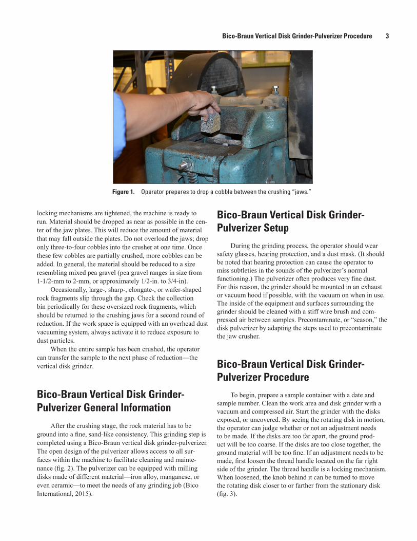
The Sturtevant open-door overhead eccentric jaw crusher is the workhorse of the reduction process. “Open door” refers to a design that exposes the inner workings of the crusher and allows for ease of cleaning and maintenance of the equipment (fig. 1). The jaw crusher works by compressing and shearing rock cobbles between a swing motion plate and an immovable plate. The two plates are referred to as the “jaw.”
The jaw crusher model used in the USGS Rock Preparation Laboratory has a 2- by 6-in. feed opening, a stationary plate, an adjustable hinge plate, and a discharge chute through which crushed material drops into a metal collection bin. Both the hinged and stationary jaw plates are made of slightly curved, partially corrugated manganese steel. The plates are mounted in a V configuration. At the bottom of the V, a gap continuously opens and closes as the hinge plate swings forward and back. When the V is opened, or gapped, rock fragments small enough to slip through the gap
do so into a collection bin or box. Fragments too large to pass through the gap continue to be crushed between the station-ary and hinged plates until they too are reduced to a size that accumulates in the bin. The crushed material should resemble gravel. Adjustments to the gap width can be made by turning the hand wheel at the front of the machine. This feature allows the operator to temporarily widen the gap and coarse-crush an especially hard rock before crushing the same rock a second time to a finer grade.
Sturtevant Jaw Crusher SetupThe jaw crusher and work area should be cleaned
thoroughly before work begins. Clean equipment and work area minimize the possibility of cross contamination. Safety glasses, a dust mask, hearing protection, a stiff brush, a collec-tion bin, a removable cover for the feed opening, and sample bags or containers will be needed for the crushing procedure. Note that the operator’s hands and clothing should never go past the opening at the top of the jaw crusher. Keeping limbs and sleeves well away from moving parts will prevent injury. If the laboratory facility is equipped with a dust collection system, it should be turned on before any processing begins. Installation of a dust collection system is recommended to remove rock dust particles from the air and prevent inhalation.
Before using the jaw crusher to reduce material, two sample containers should be labelled with the sample name. One container will store an uncrushed representative sample of the whole rock; the second container will store the crushed material. A saved sample of the original whole rock becomes a visual reference, a thin section source, or material stored for future analyses.
Sturtevant Jaw Crusher ProcedureTo begin, brush the plates with a stiff-bristled brush,
preferably a steel-wire brush. Use a vacuum cleaner and compressed air to remove any dust or particulates on or around the jaws, in the bin, and in the wider work space. After cleaning, start the crusher. Drop a few pieces of the first rock sample into the jaws. These first few pieces should be coarsely crushed, collected in the bin, and discarded. This step “seasons the jaws.” Upon placing material in the jaw crusher, the cover should be placed over the feed opening to prevent rock par-ticles ejecting from the feed opening. After the “seasoning,” or precontamination step, the desired discharge size should be set between the jaw plates. This is achieved by turning the hand wheel at the front of the crusher until the hinged plate is pushed forward to the requisite gap position. A gap of approximately 1/2-in. is recommended for most crushing jobs. Once the jaw crusher is set to the preferred gap and all
Bico-Braun Vertical Disk Grinder-Pulverizer Procedure 3
locking mechanisms are tightened, the machine is ready to run. Material should be dropped as near as possible in the cen-ter of the jaw plates. This will reduce the amount of material that may fall outside the plates. Do not overload the jaws; drop only three-to-four cobbles into the crusher at one time. Once these few cobbles are partially crushed, more cobbles can be added. In general, the material should be reduced to a size resembling mixed pea gravel (pea gravel ranges in size from 1-1/2-mm to 2-mm, or approximately 1/2-in. to 3/4-in).
Occasionally, large-, sharp-, elongate-, or wafer-shaped rock fragments slip through the gap. Check the collection bin periodically for these oversized rock fragments, which should be returned to the crushing jaws for a second round of reduction. If the work space is equipped with an overhead dust vacuuming system, always activate it to reduce exposure to dust particles.
When the entire sample has been crushed, the operator can transfer the sample to the next phase of reduction—the vertical disk grinder.
Bico-Braun Vertical Disk Grinder-Pulverizer General Information
After the crushing stage, the rock material has to be ground into a fine, sand-like consistency. This grinding step is completed using a Bico-Braun vertical disk grinder-pulverizer. The open design of the pulverizer allows access to all sur-faces within the machine to facilitate cleaning and mainte-nance (fig. 2). The pulverizer can be equipped with milling disks made of different material—iron alloy, manganese, or even ceramic—to meet the needs of any grinding job (Bico International, 2015).
Bico-Braun Vertical Disk Grinder-Pulverizer Setup
During the grinding process, the operator should wear safety glasses, hearing protection, and a dust mask. (It should be noted that hearing protection can cause the operator to miss subtleties in the sounds of the pulverizer’s normal functioning.) The pulverizer often produces very fine dust. For this reason, the grinder should be mounted in an exhaust or vacuum hood if possible, with the vacuum on when in use. The inside of the equipment and surfaces surrounding the grinder should be cleaned with a stiff wire brush and com-pressed air between samples. Precontaminate, or “season,” the disk pulverizer by adapting the steps used to precontaminate the jaw crusher.
Bico-Braun Vertical Disk Grinder-Pulverizer Procedure
To begin, prepare a sample container with a date and sample number. Clean the work area and disk grinder with a vacuum and compressed air. Start the grinder with the disks exposed, or uncovered. By seeing the rotating disk in motion, the operator can judge whether or not an adjustment needs to be made. If the disks are too far apart, the ground prod-uct will be too coarse. If the disks are too close together, the ground material will be too fine. If an adjustment needs to be made, first loosen the thread handle located on the far right side of the grinder. The thread handle is a locking mechanism. When loosened, the knob behind it can be turned to move the rotating disk closer to or farther from the stationary disk (fig. 3).
Figure 1. Operator prepares to drop a cobble between the crushing “jaws.”

4 A Process for Reducing Rocks and Concentrating Heavy Minerals
While the rotating disk is spinning, turn the knob counterclockwise to bring the stationary and rotating disks closer together. In general, the disks should have a gap between them no wider than 0.3 millimeters (mm) to 0.7 mm, or about the width of a mechanical pencil lead. When the operator has adjusted for the desired gap and tightened the thread handle to prevent disk slippage, the disk cover should be lowered and the sample at-hand ready for grinding. The most convenient way to feed material into the disk pulverizer is with a paper cup or scoop. Pour the crushed material into the hopper situated to the left and slightly above the covered grinding disks. A slow, steady pour is most effective because it minimizes disk over-heating and guarantees output consistency. The operator can judge the quality of the reduction by looking at and feeling the output product. The ground material should have the look and feel of fine, well-sorted sand. If necessary, readjust the disk gap until the ground output is uniformly fine grained. A fine-grained
product increases the likelihood that whole rock mineral constituents have been disaggregated. Once the entire sample is ground, the pulverizer must be cleaned and readied for the next crushed sample. When the grinding step is completed, the samples are ready to be sieved for even finer grain separation and grading using a sieve shaker.
Tyler Ro-Tap Test Sieve Shaker General Information
W.S. Tyler Company, a subsidiary of Haver Tyler, Inc., developed their Ro-Tap® Test Sieve Shakers in the early 1900s to replicate and mechanize the hand motions most com-monly used for sieving. Sieves come in a range of diameters and mesh sizes. For samples large and small, 12-, 8-, or 4-in.
Rotating disk
Stationary disk
Figure 2. Disk grinder opened to expose manganese grinding disks. The rotating disk spins vertically when the Bico grinder is closed.
Figure 3. Disk grinder adjustment assembly showing the thread handle and end lock knob.
Thread handle
Lock knob
Tyler Ro-Tap Test Sieve Shaker Procedure 5
diameter pans are available, and mesh, or screen sizes, can be larger than 1 in. (25.4 mm) and smaller than 0.0017 in. (45 microns [um]) (W.S. Tyler Industrial Group, 2013). The Tyler Ro-Tap Test Sieve Shaker used in the USGS Rock Preparation Laboratory in Denver, Colo., holds 8-in. diameter stainless steel sieves. These sieves hold several hundred grams of ground material, are durable, and, if properly cleaned between samples, are not a source of contamination.
Tyler Ro-Tap Test Sieve Shaker Setup
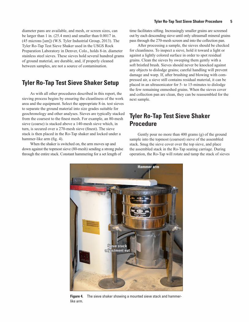
As with all other procedures described in this report, the sieving process begins by ensuring the cleanliness of the work area and the equipment. Select the appropriate 8-in. test sieves to separate the ground material into size grades suitable for geochronology and other analyses. Sieves are typically stacked from the coarsest to the finest mesh. For example, an 80-mesh sieve (coarse) is stacked above a 140-mesh sieve which, in turn, is secured over a 270-mesh sieve (finest). The sieve stack is then placed in the Ro-Tap shaker and locked under a hammer-like arm (fig. 4).
When the shaker is switched on, the arm moves up and down against the topmost sieve (80-mesh) sending a strong pulse through the entire stack. Constant hammering for a set length of
Figure 4. The sieve shaker showing a mounted sieve stack and hammer-like arm.
time facilitates sifting. Increasingly smaller grains are screened out by each descending sieve until only ultrasmall mineral grains pass through the 270-mesh screen and into the collection pan.
After processing a sample, the sieves should be checked for cleanliness. To inspect a sieve, hold it toward a light or against a lightly colored surface in order to spot residual grains. Clean the sieves by sweeping them gently with a soft bristled brush. Sieves should never be knocked against any objects to dislodge grains; careful handling will prevent damage and warp. If, after brushing and blowing with com-pressed air, a sieve still contains residual material, it can be placed in an ultrasonicator for 5- to 15-minutes to dislodge the few remaining enmeshed grains. When the sieves cover and collection pan are clean, they can be reassembled for the next sample.
Tyler Ro-Tap Test Sieve Shaker Procedure
Gently pour no more than 400 grams (g) of the ground sample into the topmost (coarsest) sieve of the assembled stack. Snug the sieve cover over the top sieve, and place the assembled stack in the Ro-Tap seating carriage. During operation, the Ro-Tap will rotate and tamp the stack of sieves
Hammer arm
Sieve stackadjustment nut
Sieve stackadjustment nut

6 A Process for Reducing Rocks and Concentrating Heavy Minerals
quickly to facilitate movement of the material within and through the sieves, so securing the sieve stack is crucial. The sieves should be fully seated within the raised rim of the seat-ing carriage to prevent slippage during operation. The height of the seating carriage can be adjusted to accommodate up to eight stacked sieves. Two wingnuts attached at the posts of the Ro-Tap can be loosened to raise or lower the carriage to the height of the stack. Once the correct height has been achieved, the wingnuts must be securely tightened.
When the Ro-Tap is secured and ready to operate, the technician should set the desired run time on the built-in timer. The USGS laboratory programs a run time of 4 minutes for a common sieve separation utilizing four sieves. The Ro-Tap is turned on by pressing the START/STOP button on the timer. The machine will immediately begin to rotate and tamp the sieves, generating a very loud banging noise. The USGS rock preparation facility houses the Ro-Tap within a sound-dampening cupboard that is closed when the machine is in operation.
Once the Ro-Tap times out, the machine will stop auto-matically, and the cupboard can be opened. Remove the sieve stack from the shaker, being careful not to tip or drop it. Sepa-rate the sieves one at time, carefully pouring the accumulated material from each sieve onto a clean, white paper (fig. 5).
Pick up two sides of the paper, and funnel the material into a prelabeled sample container. The label should indicate the mesh, or specific sieve, size as in Sample #XXX1, 240-mesh. Empty all sieves into their own labeled container, reassemble the stack, add another approximately 400 g of sample, and place the stack into the Ro-Tap. Repeat this process until the entire sample has been sifted.
After all of the material has been separated using sieves and the sieve shaker, the operator can judge the true effective-ness of the grinding process. Ideally, at least 200 g of ground material should sift into the 270-mesh pan. This size frac-tion is suitable for a number of subsequent analytical tests. If insufficient material shakes into the 270-mesh pan, the larger grains must be recombined, repulverized in the disk grinder,
and sieved a second time. When the sieving work is complete, the working area and Ro-Tap should be cleaned for the next user or sample. The sample(s) is (are) now ready for density separation using the Wilfley Table.
Wilfley Table General Information
Now that the whole rock has been reduced and sieved, it is ready for winnowing on the Wilfley Table. Winnowing is the process of separating dust and light, fine rock particles from heavier, discrete mineral grains. The Wilfley Table is the first step in the mineral concentration process. Also known as a water table or shaking table, the Wilfley Table was designed by Arthur R. Wilfley in 1896 and first used at his stamp mill in Colorado (Niebur, 1976). As Rocky Mountain miners were aware, sulfides of lead, iron, and zinc were hard to separate from gold and other lucrative metals. A method was needed to remove the gangue from the profitable metal. Wilfley put his mind to a solution and eventually developed a water table. The prototype Wilfley Table was constructed of pine boards and had fewer ridges than contemporary models. Today’s Wilfley is made of hardwood coated with a 5-mm layer of white rub-ber, but its overall design has not changed significantly in the past 120 years (fig. 6).
The Wilfley Table has been in constant use by miners and metallurgists since its invention. It has proven more than effective at separating precious metals from low-grade ores. In 1987, B.L. English and others at the U.S. Geological Survey experimented with the Wilfley Table to recover fine-grained and flour gold from Snake River sediments (English, 1987). The experiment confirmed the recovery efficiency of the water table and suggested that in conjunction with heavy liquids and the Frantz Magnetic Separator (both described in later sections of this report), the Table could be used to concentrate other heavy minerals including pyrite, galena, ilmenite, and zircon.
Figure 5. Sieved material poured from specific sieves onto white paper.
Powder mesh
Fine meshCoarse mesh
Wilfley Table Setup 7
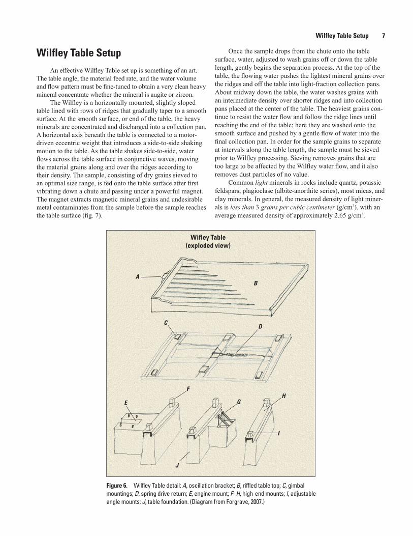
Figure 6. Wilfley Table detail: A, oscillation bracket; B, riffled table top; C, gimbal mountings; D, spring drive return; E, engine mount; F–H, high-end mounts; I, adjustable angle mounts; J, table foundation. (Diagram from Forgrave, 2007.)
Wilfley Table SetupAn effective Wilfley Table set up is something of an art.
The table angle, the material feed rate, and the water volume and flow pattern must be fine-tuned to obtain a very clean heavy mineral concentrate whether the mineral is augite or zircon.
The Wilfley is a horizontally mounted, slightly sloped table lined with rows of ridges that gradually taper to a smooth surface. At the smooth surface, or end of the table, the heavy minerals are concentrated and discharged into a collection pan. A horizontal axis beneath the table is connected to a motor-driven eccentric weight that introduces a side-to-side shaking motion to the table. As the table shakes side-to-side, water flows across the table surface in conjunctive waves, moving the material grains along and over the ridges according to their density. The sample, consisting of dry grains sieved to an optimal size range, is fed onto the table surface after first vibrating down a chute and passing under a powerful magnet. The magnet extracts magnetic mineral grains and undesirable metal contaminates from the sample before the sample reaches the table surface (fig. 7).
Once the sample drops from the chute onto the table surface, water, adjusted to wash grains off or down the table length, gently begins the separation process. At the top of the table, the flowing water pushes the lightest mineral grains over the ridges and off the table into light-fraction collection pans. About midway down the table, the water washes grains with an intermediate density over shorter ridges and into collection pans placed at the center of the table. The heaviest grains con-tinue to resist the water flow and follow the ridge lines until reaching the end of the table; here they are washed onto the smooth surface and pushed by a gentle flow of water into the final collection pan. In order for the sample grains to separate at intervals along the table length, the sample must be sieved prior to Wilfley processing. Sieving removes grains that are too large to be affected by the Wilfley water flow, and it also removes dust particles of no value.
Common light minerals in rocks include quartz, potassic feldspars, plagioclase (albite-anorthite series), most micas, and clay minerals. In general, the measured density of light miner-als is less than 3 grams per cubic centimeter (g/cm3), with an average measured density of approximately 2.65 g/cm3.
Wifley Table(exploded view)
AB
CD
E
F
GH
I
J

8 A Process for Reducing Rocks and Concentrating Heavy Minerals
Heavy minerals common to many rocks include zircon, apatite, amphiboles such as hornblende and actinolite, most precious metals, and some rare earth-bearing minerals such as bastnäsite and monazite. Heavy minerals have a density greater than 3 g/cm3 (Mindat, 2014).
Minerals with an intermediate density are often com-pound grains, or grains consisting of intergrown lights and heavies. An example would be a grain composed of both quartz and amphibole.
Wilfley Table ProcedureAt the USGS Wilfley Laboratory in Denver, Colo., the
following procedure is applied to all samples whether the heavy mineral of interest is an amphibole or zircon. When starting, the Wilfley Table should be clean and free of contami-nants. A binocular microscope with a light source, 3-in. and 7-in. diameter watch glasses, disposable gloves, safety glasses, and 250 milliliters (mL) of a 10 percent hydrochloric acid (HCl) solution are needed for this procedure.
The table is set at a permanent slope of 5 degrees from the horizontal. This slope consistently separates grains with a specific gravity of greater than 3.2 g/cm3 and ranging in size from 80 mesh to 270 mesh. Once the properly sized material is loaded into the hopper above the Wilfley table, the water is turned on and adjusted for mineral separations. A small amount of material is released onto the table so that separation can be visually determined. Grains should separate according their spe-cific density. If the material plume is not separating into obvious light, intermediate, and heavy fractions, the water pattern will need to be readjusted. This adjustment is made by reducing or increasing the water flow and turning the paddle regulators (located along the top edge of the table) to better control and direct individual streams of water. As the plume begins to split
into discrete densities, the grains coming off the end, or far left side, of the table are collected and examined in a binocular microscope. Grains can be collected by holding a watch glass under the far left discharge corner of the table (fig. 8).
When sufficient grains collect on the watch glass, remove the glass to a microscope and visually examine the concentrate. If the concentrate is dominated by the mineral of interest—90 percent or better—the table is correctly set up to receive the entire sample. The hopper feed should then be adjusted for a slow, continuous delivery of sample along the chute, under the magnet, and onto the table. If, however, the collected grains are a mix of light and heavy minerals, make additional fine adjustments to the water flow and pattern. Continue to look at the grains coming off the table end and keep finessing the water until good separation is visible in the microscope.
The difficulty with the Wilfley process is water flow. If the water is flowing onto the table too rapidly or in too great a volume, all grains will wash off immediately. If water is flowing onto the table with insufficient energy, grains will not move. If water is not well distributed across the entire table surface, grains will wash off randomly. Adjusting the volume and flow pattern of the water requires patience and repeated microscopic examination of the grains discharging at the heavy end of the table. The whole procedure requires a careful eye and a deft touch, thus elevating the Wilfley procedure to an art.
When the entire sample has been processed, the collected light and intermediate fractions can usually be discarded as ordinary wet waste. The heavy concentrate should be washed from its collection pan onto a large watch glass. The glass should then be placed under a drying light. All collection pans should be thoroughly rinsed and stacked to dry. To care for the table surface, it must be rinsed with tap water and then washed with a 10 percent solution of HCl to remove any stains or trace contaminants associated with the sample. Wear gloves and
Magnet
Feed chute
Water lines
Figure 7. Photograph of the sample as it passes under the magnet before dropping to the riffled surface.

Frantz Magnetic Separation General Introduction 9
protective eyewear during this process. Using paper towels, gently wipe the HCl across the entire surface of the table and gently rub off any stains. Give the table a final, thorough rinse with tap water and dry using a steady stream of compressed air or blot with paper towels.
Frantz Magnetic SeparationThe Frantz Isodynamic Magnetic Separator is an important
device in the mineral concentration process because it separates and concentrates dry mineral grains according to their paramag-netic susceptibility.
To understand paramagnetism, a simple review of electron behavior is necessary. At the center of an atom is a nucleus. Sur-rounding the nucleus are shells, also known as orbits or orbitals. An atomic nucleus can be surrounded by one or multiple shells. The shell closest to the nucleus is referred to as the “K” shell; the next closest shell is called the “L” shell. Successive shells, resembling the expanding rings of a water ripple, are labelled K, L, M, and so forth (fig. 9).
Shells contain specific numbers of electrons. The hydro-gen atom, for example, possesses only one electron. This single electron orbits the K shell. The silicon (Si) atom has a total of 14 electrons. These electrons are arranged, or config-ured, as two electrons in the K shell, eight electrons in the L shell, and four electrons in the M shell (fig. 10).
The number of electrons for any element is shown on the periodic table of elements. On the periodic table, the symbol H represents the hydrogen atom. The numeral 1 in the upper left corner of the hydrogen symbol indicates that H has one electron. Silicon, or Si, possesses 14 electrons as indicated by the numeral 14 in the upper left corner of the symbol.
In general, a K orbital can contain no more than two electrons; L and M orbitals can hold up to eight electrons each. If any one of these three orbitals, or shells, contains only one
electron, it is considered an incomplete shell. A complete shell contains an even number of electrons aligned parallel to each other and spinning within their orbits right-to-left and left-to-right in pairs. Paired, opposite spin has a balancing effect, mak-ing a substance nonmagnetic. Conversely, a single or unpaired electron in an incomplete shell moves in a random direction, having no other electron with which to align or spin (fig. 11).
This unpaired state results in magnetic susceptibility. When an induced magnetic field, such as that generated by the Frantz Magnetic Separator, is applied to mineral substances with incomplete shells, solitary electrons within mineral struc-tures will sometimes align with and spin in the same direction as the external field causing the mineral to behave as a mag-netic substance. When the external magnetic field is removed, the mineral substance reverts to a nonmagnetic state. Tempo-rary magnetic behavior is otherwise known as paramagnetism, which can only be achieved by introducing unpaired electrons to a variable external, or induced, magnetic field.
Frantz Magnetic Separation General Introduction
The earliest known use of a magnet as a mineral separation tool dates to antiquity. An object found in South America in the early 1960s suggests that naturally occur-ring, strongly magnetic hematite (Fe2O3) was used by Olmec people 2,000 years ago to locate and extract iron ore used to manufacture mirrors and decorative objects (Carlson, 1975). Though the literature is scant on the subject, it’s not too difficult to imagine other ancient people using the mineral, magnetite (Fe3O4) to locate native iron deposits, iron that was subsequently mined, smelted, and fashioned into weapons, tools, and ornaments. Miners in 19th century Cornwall relied on the earliest known process magnetic separator invented
Figure 8. Wilfley Table water flow and plume separation.
Fine to powdered sample plume
Regulated water flow
Surface ridges or riffles

10 A Process for Reducing Rocks and Concentrating Heavy Minerals
by John Wetherill. Wetherill’s Magnetic Separator consisted of two continuously running belts that passed under mounted magnets. Wetherill’s original device could process 10 tons of ore daily (Earl, 1994). In 1936, Samuel G. Frantz obtained a patent for his own separation device, the Isodynamic Separator, and by 1971 Frantz’s invention was in use world-wide (S.G. Frantz, 2015).
Frantz Magnetic Separator SetupThe Frantz Isodynamic Separator relies on a magnet situated
above and parallel to a slightly sloped two-channel aluminum track positioned to accept continuous-feed, dry mineral material. The strength of the field created by the magnet can be varied by a controller; the magnetic field can be set as low as 0.01 amperes to separate highly susceptible minerals from a granular sample, and as high as 1.70 amperes to segregate minerals with a low suscep-tibility. As the mineral sample feeds from a glass hopper mounted on a mast above the two-channel track, it is propelled downward under the magnet by means of vibration (fig. 12).
Vibration can be adjusted to slow down or speed up both the feed rate and movement of the mineral grains toward the end of the track. As the grains pass under the magnet, they separate according to their paramagnetic susceptibil-ity; nonmagnetic grains split into the right channel, while temporarily magnetic grains concentrate in the left channel. Two small canisters placed at the end of the track capture the separated grains.
Frantz Magnetic Separator Procedure
The Frantz Separator is easy to adjust for optimal mineral separation. For best results, the sample should range in size from 50 to 150 microns (270- to 100-mesh). The magnet, mounted on a horizontal axis, should be tilted approximately 15 degrees toward the left channel. The feed rate and vibration tempo should be adjusted to slow and low. (Continuous large clusters of feed grains tend to be moved by momentum rather than attraction. Slowing both the feed rate and vibrational movement of the material eliminates clustering.) The purity
Figure 9. K-L-M-N orbital shells and electron distribution and configuration for five elements.
K K
Carbon
L
K
N
M
L
K
M
L
K
HeliumHydrogen
Calcium
Molybdenum
+1
+20
+2
+42
+6

Heavy Liquids General Information 11
Figure 10. A diagram of the silicon electron configuration.
Si
SiliconElectrons per shells 2, 8, 4
Electron
Spin
Nucleus
Orbit
Figure 11. A diagram showing an unpaired electron spinning within an orbit.
of the separate depends on two things: the composition of the host rock and the quality of the mineral grains themselves. Rocks, not infrequently, contain more than one paramagnetic mineral. When processed on the Frantz, these susceptible phases may separate together at the same magnetic setting. An example of two mineral phases with the same magnetic susceptibility is actinolite and hornblende. According to Rosenblum and Brownfield (1999), these two minerals acquire magnetic behavior at an external field setting of between 0.30 and 0.60 amperes. Both minerals are monoclinic amphiboles, but only one, hornblende, is suitable for age dating. If a rock contains both of these minerals, a Frantz alternative may have to be applied to achieve separation.
The other factor affecting purity of separation—qual-ity of the grains—is a bit more straightforward. Quality is determined by the percentage of single, pure (monomineralic)
grains present in the sample. Monomineralic grains will, of course, separate in greater abundance than compound or included grains. A compound grain is a tiny fragment consist-ing of both a susceptible and a nonmagnetic mineral. Gentle grinding with an agate mortar and pestle may disaggregate compound grains. Once disaggregated, the sample can be reprocessed on the Frantz.
Samples can be visually inspected before and after Frantz processing. A first look at the sample in a binocular micro-scope alerts the technician to the composition of the rock and abundance of paramagnetic phases. After processing the sam-ple using the Frantz Magnetic Separator, the binocular scope can reveal the purity of the magnetic separate. If the mineral of interest is seen as concentrated, the process is complete. If, however, multiple phases, compound grains, or nonmagnetic grains are visible, the process must be repeated by adjusting and experimenting with magnetic settings until grains begin to visibly separate. The final paramagnetic products should then be transferred to glass vials and labelled ready for analyses.
Heavy Liquids General InformationHeavy liquids and heavy liquid separation techniques
have been used since the mid-19th century. Also known as heavy media separation or float-sink separation, heavy liquid separation relies on an organic or water-soluble liquid com-pound heavier than water to separate materials based on their densities. Density is defined as the mass of a substance per unit volume. A substance lighter or heavier than water will float or sink in water; its density determines whether it floats or sinks. The same is true of substances in heavy liquids: If heavier or lighter, or more or less dense, than the heavy liquid, the substance sinks or floats.
Sir Henry Bessemer first patented the use of calcium chloride (CaCl2) solution (a heavy liquid) in 1858, to separate coal from its more dense spoil. Though it became popular through the mid-20th century to use heavy liquid separation in the coal and ore industries, the drawbacks of its use—toxicity and evaporative loss—contributed to its gradual decline in use by the coal industry (Aplan, 2003). Heavy liquids, however, continue to be used in geology, metallurgy, and gemology laboratories to separate and concentrate minerals of interest.
Today, various heavy liquids are manufactured for spe-cific purposes. Some heavy liquids are used to separate min-eral or synthetic phases while others are used as reagents for intended chemical reactions. Common heavy liquids include bromoform (CHBr3), methylene iodide (CH2I2, abbreviated MI), and sodium polytungstate (Na6[H2W12O40]). The first two are halogenated hydrocarbons, while sodium polytungstate is a water-based heavy liquid (Hauff and Airey, 1980). For the pur-pose of heavy minerals separation, methylene iodide is most often used in the Denver USGS laboratory because of its high density and relatively low cost. MI is an organic liquid with a density of 3.325 g/cm3 at room temperature, a density three

12 A Process for Reducing Rocks and Concentrating Heavy Minerals
times greater than water (the density of water is approximately 1.00 g/cm3). Advantages of MI use in the geologic laboratory include its low viscosity and wetting power—its ability to spread throughout samples and coat the surfaces of individual mineral grains and powders. MI, as well as bromoform, is sen-sitive to light, air, and moisture, and will gradually decompose when exposed to light or stored uncovered. Discoloration of MI occurs when the liquid is exposed to light. Light exposure liberates iodine from the compound resulting in a change in color from light yellow to dark yellow, red, or brown. Toxicity, the major drawback of MI use, is relatively easily mitigated through the use of proper safety precautions and protective clothing. Although MI was originally thought to match the toxicity of bromoform, recent studies have shown that MI is
slightly less toxic than bromoform. According to one manu-facturer of heavy liquids, 25 parts per million MI have been detected in the lungs of users exposed to MI vapors for 8 hours. Parts per million is 1-1/2 times higher for bromoform exposure for the same number of hours (GeoLiquids, 2014). When handling MI, always wear safety glasses to prevent eye contact and rubber gloves and a rubber apron or lab coat to ensure protection against skin. Because MI is susceptible to light-triggered discoloration, it must be stored in a dry, dark area that is well ventilated. It must also be contained in dark glass, Teflon, or opaque plastic bottles that are resistant to the corroding effect of MI. To preserve the clarity and light straw color of the MI, a small piece of copper screen is added to the bottle after it is opened. Another favorable characteristic of
Hopper(thistle funnel)
Two-channel trackwith tan colored
non-magneticgrains
External magnet
Figure 12. Photograph of the Frantz Magnetic Separator with vibration controllers, glass hopper, sample discharge, and two-channel track for paramagnetic and nonmagnetic division.
Heavy Liquids Separation Setup 13
MI is its rinsability and recoverability from samples. Samples submerged in MI can be rinsed with technical-grade acetone (technical-grade chemicals contain trace, or negligible, amounts of impurities). Acetone washes all but the residual heavy liquid from grains and can also be used to dilute and adjust the MI to a lighter density if needed (R.C. Coleman, unpub. data, 1960). The rinsate, a mixture of acetone and MI, can be distilled to separate the acetone from the MI. The distillation process recovers the MI at a density slightly less than original—generally from 2.88 to 3.01 g/cm3. Both the reclaimed MI and acetone can be reused.
Acetone (CH3COCH3) is a colorless liquid with a fragrant odor and poses health hazards due to its flammability; toxic-ity; and narcotic, stimulating effects on the respiratory system. When handling acetone, safety glasses, rubber gloves, and a rubber apron or lab coat should be worn and checked for damage if contact with acetone occurs. Also, because acetone is highly volatile, it should always be used inside an exhaust hood to ensure adequate ventilation and reduce the risk of spark, inhalation, or eye exposure. Acetone must be stored in approved, nonreactive plastic, metal, or glass containers. Owing to its high flammability and very low flash point in vapor form, acetone should be stored away from any con-stant points of ignition, and its containment vessel should be grounded to avoid static discharge (Hauff and Airey, 1980).
If MI comes in contact with the skin it should be wiped immediately with acetone or alcohol, followed by a vigor-ous wash with soap and water. Because this wash interven-tion can strip the natural protective oils from skin, lanolin or petroleum jelly should be applied to restore this protective layer (Geoliquids, 2014). Since MI should only be handled in an exhaust hood, most spills will be contained with adequate ventilation provided. However, if a spill occurs outside the exhaust hood, the following common sense safety steps should be implemented in the order listed:
• Switch off the central air conditioning to avoid the spread of vapors.
• Cover the face with a self-contained breathing unit or respirator with filter to avoid inhalation.
• Cover street clothes and shoes with disposable, protec-tive garments.
• Locate the spill cleanup kit in the laboratory. The kit contains absorbent material that should be sprinkled over the spill and allowed to fully absorb the heavy liquid. The saturated absorbent can then be swept up with a broom and dustpan and discarded as a hazard-ous waste. Once the absorbent is swept up, pour a modest volume of acetone over the spill area to remove any residual heavy liquid.
• Report the spill to the proper safety-enforcement personnel.
If a heavy liquid spill occurs in the exhaust hood, the liquid can be neutralized by squirting acetone into it and wip-ing up with absorbent paper (Hauff and Airey, 1980). This saturated paper should be disposed of as special waste. In the USGS Heavy Liquids Laboratory, wastepaper and used filter papers are discarded in a wire mesh basket placed in an exhaust hood. Over time, MI and acetone evaporate from the wastepaper, and the toxic vapors dissipate. The dry wastepaper can be discarded as standard trash.
Heavy Liquids Separation SetupAt this stage, samples have been winnowed on the
Wilfley Table and divided into magnetic and nonmagnetic grains. In general, magnetic mineral grains are heavier than nonmagnetic grains. These heavy fractions are now ready to be processed in heavy liquid.
All safety protocols should be observed as a first step in the heavy liquids setup. Wear goggles, disposable gloves, and a rubber or vinyl apron. Since the work will be conducted in an exhaust hood, ascertain that the hood lighting and ventila-tion fans are working properly.
Obtain the following laboratory supplies (fig. 13):• Two amber separatory funnels fitted with greased
stopcocks;
• Two wide-mouth funnels (either glass or plastic);
• Two rubberized vacuum gaskets;
• Two amber vacuum flasks;
• two ring stands;
• One watch glass, filter papers, one 250 mL glass or plastic beaker, and optional stirring rod.
Before assembling the apparatus, all glassware should be examined for cracks and cleanliness. The separatory funnels and stopcocks should be examined for any dam-age or wear that may cause the heavy liquid to leak during separation.
Place the ring stands side-by-side in the exhaust hood. Raise and tighten the rings to a height that will position each separatory funnel stem approximately 1-in. above the rim of each flask. Lightly grease two ground-glass or Teflon stop-cocks with vacuum grease. Fit the stopcocks into the separa-tory funnels, turning both at least one full revolution to evenly spread the grease. Carefully place the separatory funnels in the rings. Label one amber vacuum flask as HL (Heavy Liquid). Place this flask on the left-side ring stand under the separatory funnel. Label the second flask as HL Wash and place under the funnel on the right-side ring stand. Press a rubberized gasket into the mouth of each flask. Next, snug a glass or plastic

14 A Process for Reducing Rocks and Concentrating Heavy Minerals
funnel into each gasket. Select filter paper of a size that will fit snugly within the left-side plastic or glass funnel. In order to properly fit the filter paper, it must first be folded in half and then folded in half again. Gently push the tip of the folded filter paper into the stem of the left-side funnel and unfold to form a cone. The flasks can now be connected to vacuum hoses that will accelerate filtering.
Heavy Liquid Separation Procedure
Fill at least one 500-mL Nalgene or other durable plastic squirt bottle with technical-grade acetone. Remove a bottle of MI from its dark storage cabinet. After double-checking that the stopcocks are closed, pour MI into the left-side separatory funnel using the minimal amount needed for the separation. Never fill the separatory funnel above halfway. A half-full separatory funnel is less likely to become unbalanced, tip, and spill than an over-filled funnel. Replace the cap on the bottle of MI, and place it out of the way.
Carefully pour the graded-mineral material into the MI liquid in the separatory funnel. Heavy mineral grains, or grains with a density greater than the density of the MI (+3.32 g/cm3), will begin to sink down through the heavy liquid column and accumulate at the bottom of the separa-tory funnel. Mineral grains with a density lighter than that of the MI will float to the top of the liquid column. It may be necessary to agitate the liquid to ensure wetting of all grains. To agitate the liquid, use a stirring rod in a gentle back-and-forth motion. Place the contaminated stirring rod in the clean beaker. As the grains begin to separate, the separatory funnel should be covered with the watch glass to prevent airborne
contamination during settling. The time needed for settling will depend upon the composition and size of the ground material and can vary from minutes to hours. Once the grains have settled, the heavy liquid is ready to be decanted. Confirm that the flask with the filtered funnel is positioned below the separatory funnel. The stem of the separatory funnel should be just inside the filtered funnel. (fig. 14).
With one hand on the separatory funnel and the other on the stopcock, carefully and quickly open the stopcock to allow only the heavy accumulates to discharge. As soon as the heavy grains are flushed into the filter paper, quickly close the stopcock. Unclamp the left-side vacuum hose and switch on the vacuum to help pull the excess heavy liquid through the filtered funnel and into the flask. When the last visible drops of MI are vacuumed into the flask, switch off the vacuum and re-clamp the hose. Using gloved fingers, transfer the satu-rated filter paper with sample grains from the left-side to the right-side glass or plastic funnel. Alternatively, the glass or plastic funnel itself, with filter paper and sample in place, can be carefully lifted and transferred to the gasketed mouth of the right-side flask. (Be mindful of funnel stems!) Unclamp and switch on the vacuum line to the right-side flask. Using the prepared acetone bottle, squirt and rinse the filter paper and the sample thoroughly and repeatedly to wash MI from the heavy grains (also called the “sink fraction”). When all of the acetone rinse has been vacuumed into the flask, the paper filter cone containing the sink fraction can be transferred from the funnel to a separate ventilated hood for flat drying under a low-temperature heat lamp. Switch off and re-clamp the right-side vacuum line. Returning to the left-side separatory funnel, see that the light mineral grains (also called the “float fraction” or “floats”) have settled at the top of the heavy liquid column. The floats may now be decanted, or discharged, from the
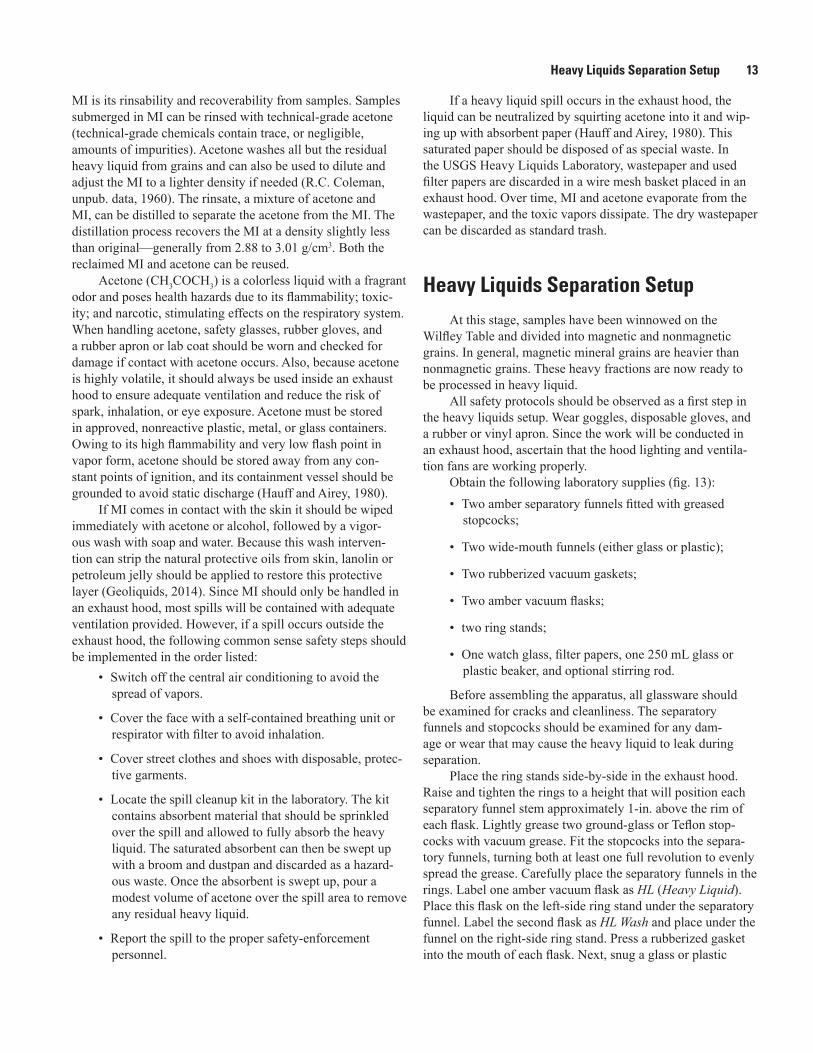
Figure 13. Photograph of the heavy liquids separation set up. Amber glassware is used to reduce heavy liquid light exposure.
Vacuum flaskwith gasket
Vacuum line
WidemouthfunnelSep funnel
withstopcock

Conclusion 15
separatory funnel. Line a plastic or glass funnel with a new, folded filter paper; snug the funnel into the vacuum gasket; unclamp the left-side vacuum hose; switch on the vacuum; and open the stopcock. Be prepared to quickly close the stopcock because the volume of heavy liquid flushing into the filtered funnel may exceed the capacity of the funnel. When the heavy liquid is vacuumed from the sample, clamp the vacuum hose and transfer the filter paper containing the decanted float frac-tion to the right-side flask. Open the right-side vacuum line, and wash the sample thoroughly with acetone. Remove the filter paper and mineral fraction to the drying hood. Due to the volatility of the acetone, this drying process tends to be quick. Once dried, the mineral fractions should be stored in appropri-ately labeled containers—either a capped glass vial or plastic, hinged-lid pillbox. An appropriate label includes the sample name or number and indicates that the content has been processed through MI and is either the heavy or light fraction (#XXX1, MI sink).
Once the heavy liquid separation work has been com-pleted, the glassware and work areas should be cleaned. First, the liquids collected in each of the flasks should be poured into proper storage containers for later reuse or distillation. The undiluted methylene iodide (in the left-side flask) should be filtered back into its original bottle. The acetone-MI wash (in the ride-side flask) should be stored in any clean, recycled bottle for later distillation. All glassware used in the separation procedure must be rinsed with acetone and then washed with soap and water before air drying. Hoods and work surfaces must be wiped with a damp cloth.
This completes the mineral separation process. Samples are now ready for trace element analysis, ion geochronology analysis, mass spectrometry, or X-ray fluorescence or diffrac-tion analysis.
Conclusion
To obtain clean heavy mineral concentrates from whole rock, the laboratory professional must crush the rock, grind it into a sand-like consistency, and then sieve the ground mate-rial to a uniform size range. A jaw crusher and disk grinder are must-have equipment to reduce whole rock to sand-sized particles. An automated sieve shaker is an essential tool for optimal particle sizing. When these mechanical reducing steps are completed, the work of separating heavy mineral grains from extraneous, or undesirable, particles begins.
Separation is achieved with a Wilfley Table, a Frantz Magnetic Separator, and methylene iodide. The Wilfley Table is used first to remove light mineral grains from the sieved product while simultaneously concentrating heavy grains. The collected heavy grains are then processed on the Frantz Magnetic Separator. The magnetic separator can be adjusted to divide nonmagnetic and unwanted paramagnetic grains from their opposites. Finally, the sample, now concentrated into a heavy, paramagnetic fraction, is processed through the heavy liquid—methylene iodide. By pouring the paramagnetic sample into a column of methylene iodide, the last remaining light and compound grains are eliminated from the concen-trate. If the separation steps described in this report are closely followed and carefully executed, heavy minerals of interest—including zircon, monazite, apatite, rutile, xenotime, amphi-boles (some), sulfides, and oxides—will be concentrated. The mineral concentrates can then be analyzed to develop a more comprehensive understanding of the Earth’s history. Methods of analysis can include isotope measurements, trace element chemistry, laser ablation, and sensitive high resolution ion microprobe (SHRIMP) analysis.
Figure 14. Closeup photograph of the separatory funnel stem inside the filtered funnel to prevent splash.

16 A Process for Reducing Rocks and Concentrating Heavy Minerals
There are no shortcuts in the comminution and mineral concentration process. The importance of methodical, consci-entious sample preparation cannot be overstated—failure to clean a single piece of equipment, poor grinding or sieving, hurried Wilfley winnowing, or Frantz processing will produce mineral concentrates that are improperly sized, impure, and not particularly useful to research analysts. Reliable analytical output begins with reliable mineral input.
References Cited
Aplan, F.F., 2003, Chap. 6—Gravity concentration, in Fuerstenau, M.C., and Han, K.N., eds., Principals of mineral processing: Littleton, Colo., Society for Mining, Metallurgy, and Exploration, Inc., p. 195–202.
Bico Inc., 2015, UA Pulverizer instruction manual: Bico, Inc., accessed December 28, 2014, at http://www.bicoinc.com/ua.html.
Carlson, J.B., 1975, Multidisciplinary analysis of an Olmec hematite artifact from San Lorenzo, Veracrus, Mexico: Science, 1975, v. 189, p. 753–60.
Earl, Bryan, 1994, Cornish mining—The techniques of metal mining in the west of England, past and present: Cornish Hillside Publications, v. 2, p. 97.
English, B.L., Desborough, G.A., and Raymond, W.H., 1987, A mechanical panning technique for separation of fine-grained gold and other heavy minerals: U.S. Geological Survey Open-File Report 87–0364.
Forgrave, Michael, 2007, Mill machines—The Wilfley Table: Copper Country Explorer, posted October, 20, 2006, accessed October 14, 2014, at http://www.coppercountryexplorer.com/2006/10/stamps-jigs-and-wifleys/.
Geoliquids, Inc., 2014, MI-GEE brand methylene iodide: Geoliquids, Inc., Chemical Based Liquids, Bulletin No. 32.
Hauff, P.L., and Airey, Joseph, 1980, The handling, hazards, and maintenance of heavy liquids in the geologic labora-tory: U.S. Geological Survey Circular 827, 24 p.
Mindat.org, 2014, Mineral densities: Mindat.org, accessed November 13, 2014, at http://www.mindat.org/searchdensity.
Nelson, S.A., 2013, Physical properties of minerals course materials: Tulane University, accessed April 23, 2015, at http://www.tulane.edu/~sanelson/eens211/physprop.htm.
Niebur, J.E., 1976, Arthur Redman Wilfley—Inventor and entrepreneur: Colorado Historical Society, p. 124–149.
Rosenblum, Sam, and Brownfield, I.K., 1999, Magnetic sus-ceptibilities of minerals: U.S. Geological Survey Open-File Report 99–529.
S.G. Frantz Company, 2015, Company history: S.G. Frantz Com-pany, accessed December 30, 2014, at http://www.sgfrantz.com/history.htm.
Sturtevant, Inc., 2015, Our history: Sturtevant, Inc., accessed January 12, 2015, at http://www.sturtevantinc.com/about-us/our-history/.
W.S. Tyler Industrial Group, 2013, Tyler test sieve shakers—Product manual, revised 2013: Mentor, Ohio, Haver Tyler, Inc., p. 1–3, accessed January 15, 2015, at http://wstyler.com/wp-content/uploads/2015/11/Product-Catalog-2.pdf.
Publishing support provided by: Denver Publishing Service Center, Denver, Colorado
For more information concerning this publication, contact:
Center Director, USGS Central Mineral and Environmental Resources Science Center Box 25046, Mail Stop 973 Denver, CO 80225 (303) 236-1562
Or visit the Geosciences and Environmental Change Science Center Web site at:
http://minerals.usgs.gov/
This publication is available online at: http://dx.doi.org/10.3133/ofr20161022


Strong and Driscoll—A
Process for Reducing Rocks and Concentrating Heavy M
inerals—Open-File Report 2016–1022
ISSN 2331-1258 (online)http://dx.doi.org/10.3133/ofr20161022