A Principled Technologies white paper commissioned ... … access with VSS enabled across two Cisco...
46
A Principled Technologies white paper commissioned by Dell Inc.
Transcript of A Principled Technologies white paper commissioned ... … access with VSS enabled across two Cisco...
A Principled Technologies white paper commissioned by Dell Inc.
Deployment of Dell M-Series blade switches in a Cisco Catalyst network
TABLE OF CONTENTS
Table of contents .................................................................................. 2
Summary ............................................................................................... 3
Features of Simple Switch Mode .............................................. 4
Sample scenarios ...................................................................... 4
Testing scenarios ................................................................................... 5
Scenario 1: Plug and play using the Dell PowerConnect M8024 switch for blade deployment into an existing network ............ 6
Scenario 2: Configuring VLANs on the internal ports of the Dell PowerConnect M8024 switch ................................................... 7
Scenario 3: Configuring multiple VLANs per internal port to connect to a server NIC with tagging enabled .......................... 8
Scenario 4: Configuring multiple Port Aggregation Groups and dedicating specific Uplinks ...................................................... 10
Scenario 5: Adding VLANs in a multi-AG configuration .......... 11
Scenario 6: Setting up a fully meshed topology ..................... 12
Scenario 7: Setting up a straight-through topology with LAG failover .................................................................................... 13
Scenario 8: Establishing access with VSS enabled across the Cisco Catalyst 6504-E switches ............................................... 14
Appendix A – Detailed scenario methodology ................................... 16
Scenario 1: Plug and play using the Dell PowerConnect M8024 switch for blade deployment into an existing network .......... 16
Scenario 2: Configuring VLANs on the internal ports of the Dell PowerConnect M8024 switch ................................................. 17
Scenario 3: Configuring multiple VLANs per internal port to connect to a server NIC with tagging enabled ........................ 20
Scenario 4: Configuring multiple Port Aggregation Groups and dedicating specific Uplinks ...................................................... 23
Scenario 5: Adding VLANs in a multi-AG configuration .......... 27
Scenario 6: Setting up a fully meshed topology ..................... 33
Scenario 7: Setting up a straight-through topology with LAG failover .................................................................................... 35
Scenario 8: Establishing access with VSS enabled across the Cisco Catalyst 6504-E switches ............................................... 38
Appendix B – Network switch configuration information .................. 45
About Principled Technologies ........................................................... 46

3
Deployment of Dell M-Series blade switches in a Cisco Catalyst network
SUMMARY
Adding a Dell™ PowerConnect™ M8024 switch or a Dell M8024 LAN
Module with a Dell PowerEdge™ M1000e modular blade enclosure to
an existing network using a Cisco® infrastructure is a straightforward
process. The addition of Simple Switch Mode on the Dell M8024
family of switches further simplifies the process, allowing integration
into a Cisco network with minimal effort.
This Principled Technologies (PT) Guide explains the deployment
process for the Dell PowerEdge M1000e modular blade enclosure
with a Dell PowerConnect M8024 switch (see Figure 1) in an existing
Cisco network. We tested two Dell PowerConnect M8024 switches in
a variety of different network deployment scenarios with two Cisco
Catalyst 6504-E switches, and discovered that Simple Switch Mode is
capable of automatically configuring the Dell PowerConnect M8024
switches to integrate with each scenario with minimal interaction
from our technicians.
Figure 1: The Dell PowerConnect M8024 switch.
NOTE: We tested with the Dell PowerConnect M8024 switches, but all
of our steps should apply to the Dell M8024 LAN Module, as well.
4
Deployment of Dell M-Series blade switches in a Cisco Catalyst network
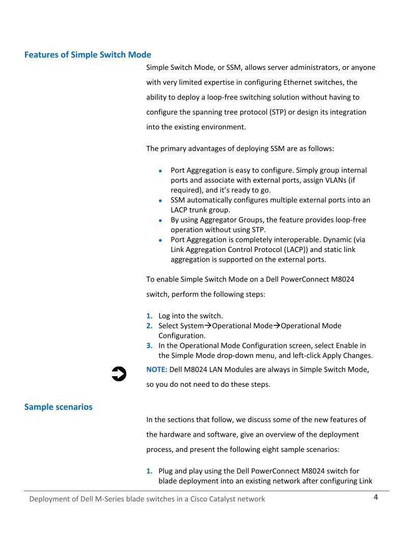
Features of Simple Switch Mode
Simple Switch Mode, or SSM, allows server administrators, or anyone
with very limited expertise in configuring Ethernet switches, the
ability to deploy a loop-free switching solution without having to
configure the spanning tree protocol (STP) or design its integration
into the existing environment.
The primary advantages of deploying SSM are as follows:
Port Aggregation is easy to configure. Simply group internal ports and associate with external ports, assign VLANs (if required), and it’s ready to go.
SSM automatically configures multiple external ports into an LACP trunk group.
By using Aggregator Groups, the feature provides loop-free operation without using STP.
Port Aggregation is completely interoperable. Dynamic (via Link Aggregation Control Protocol (LACP)) and static link aggregation is supported on the external ports.
To enable Simple Switch Mode on a Dell PowerConnect M8024
switch, perform the following steps:
1. Log into the switch. 2. Select SystemOperational ModeOperational Mode
Configuration. 3. In the Operational Mode Configuration screen, select Enable in
the Simple Mode drop-down menu, and left-click Apply Changes.
NOTE: Dell M8024 LAN Modules are always in Simple Switch Mode,
so you do not need to do these steps.
Sample scenarios
In the sections that follow, we discuss some of the new features of
the hardware and software, give an overview of the deployment
process, and present the following eight sample scenarios:
1. Plug and play using the Dell PowerConnect M8024 switch for blade deployment into an existing network after configuring Link
5
Deployment of Dell M-Series blade switches in a Cisco Catalyst network
Aggregation Control Protocol (LACP) on Cisco Catalyst 6504-E switch ports.
2. Configuring VLANs on internal ports of the Dell PowerConnect M8024 switch, while configuring the Cisco Catalyst 6504-E switch to extend those VLANs in an external Catalyst network.
3. Configuring Multiple VLANs per internal port to connect to the server NIC with Tag enabled. (An example of this would be supporting virtual machines (VMs) in the server scenario.)
4. Configuring multiple port aggregation groups (mapping aggregate groups to group-specific attached blade servers) and dedicating specific uplinks to carry that traffic to the Cisco network.
5. Adding VLANs in a multi-aggregate group configuration. 6. Setting up a meshed topology for redundancy. 7. Setting up a topology with Link Aggregation Group (LAG) failover. 8. Establishing access with VSS enabled across two Cisco Catalyst
6504-E switches.
The appendices to the Guide give detailed, step-by-step information
on how to do the deployment and provide detailed configuration
information on the hardware we used.
TESTING SCENARIOS
Our testing included establishing connections and utilizing sample
features and functions of the Dell PowerConnect M8024 switch with
the goal of showing the ease of deployment of the Dell PowerConnect
M8024 switch and accompanying Dell hardware in a Cisco Catalyst
environment. The Dell blade switch operated in Simple Switch Mode
as a port aggregator. We began each scenario with a fresh test bed,
which included a Dell PowerEdge M710 blade server in the Dell
PowerEdge M1000e modular blade enclosure connected with Dell
PowerConnect M8024 switches. We include a network diagram
showing the general configuration of our switches in our test bed for
each scenario.

6
Deployment of Dell M-Series blade switches in a Cisco Catalyst network
Scenario 1: Plug and play using the Dell PowerConnect M8024 switch for blade deployment into an existing network
In this section, we provide an overview of the plug-and-play process
with the Dell PowerConnect M8024 switch, after configuring Link
Aggregation Control Protocol (LACP) on Cisco Catalyst 6504-E switch
ports. Dell’s plug-and-play features with Simple Switch Mode allow
for quick integration of Dell blade switch into a network. We provide
detailed instructions in Appendix A.
1. On the Cisco Catalyst 6504-E switch, set up a four-port port channel with LACP using the ports that will be connected to Dell PowerConnect M8024 switch.
2. Connect cables from the Cisco Catalyst 6504-E switch to the Dell PowerConnect M8024 switch. The Dell PowerConnect M8024 switch will automatically create a Link Aggregation Group (LAG) and establish network connectivity for the blade servers into the existing network.
NOTE: Because the Dell PowerConnect M8024 switch forms the LAG
as you cable up the ports, cabling will not create loops, removing the
need for STP.
Figure 2 illustrates the completed configuration for Scenario 1.

7
Deployment of Dell M-Series blade switches in a Cisco Catalyst network
Figure 2: Graphic representation of Scenario 1.
Scenario 2: Configuring VLANs on the internal ports of the Dell PowerConnect M8024 switch
In this section, we provide an overview of configuring the VLANs on
the internal ports of the Dell PowerConnect M8024 switch, while
configuring those on the Cisco Catalyst 6504-E switch to extend those
VLANs in the external Cisco Catalyst network. VLANs allow for traffic
isolation and for granular quality of service (QoS) control over simple
subnetting, and Dell switches with Simple Switch Mode enabled offer
quick and easy VLAN configuration. We provide detailed instructions
in Appendix A.
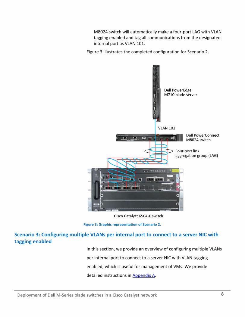
1. On the Dell PowerConnect M8024 switch, enter the Internal Port VLAN configuration screen, select a port, and change the default Untagged VLAN (we changed port 1/xg1 to VLAN 101).
2. On the Cisco Catalyst 6504-E switch, create a four-port channel group with LACP and Trunking (VLAN tagging) enabled.
3. Allow VLAN 101 through the new port channel. 4. Connect the cables from the ports of the port channel group to
the Dell PowerConnect M8024 Switch. The Dell PowerConnect
8
Deployment of Dell M-Series blade switches in a Cisco Catalyst network
M8024 switch will automatically make a four-port LAG with VLAN tagging enabled and tag all communications from the designated internal port as VLAN 101.
Figure 3 illustrates the completed configuration for Scenario 2.
Figure 3: Graphic representation of Scenario 2.
Scenario 3: Configuring multiple VLANs per internal port to connect to a server NIC with tagging enabled
In this section, we provide an overview of configuring multiple VLANs
per internal port to connect to a server NIC with VLAN tagging
enabled, which is useful for management of VMs. We provide
detailed instructions in Appendix A.
9
Deployment of Dell M-Series blade switches in a Cisco Catalyst network
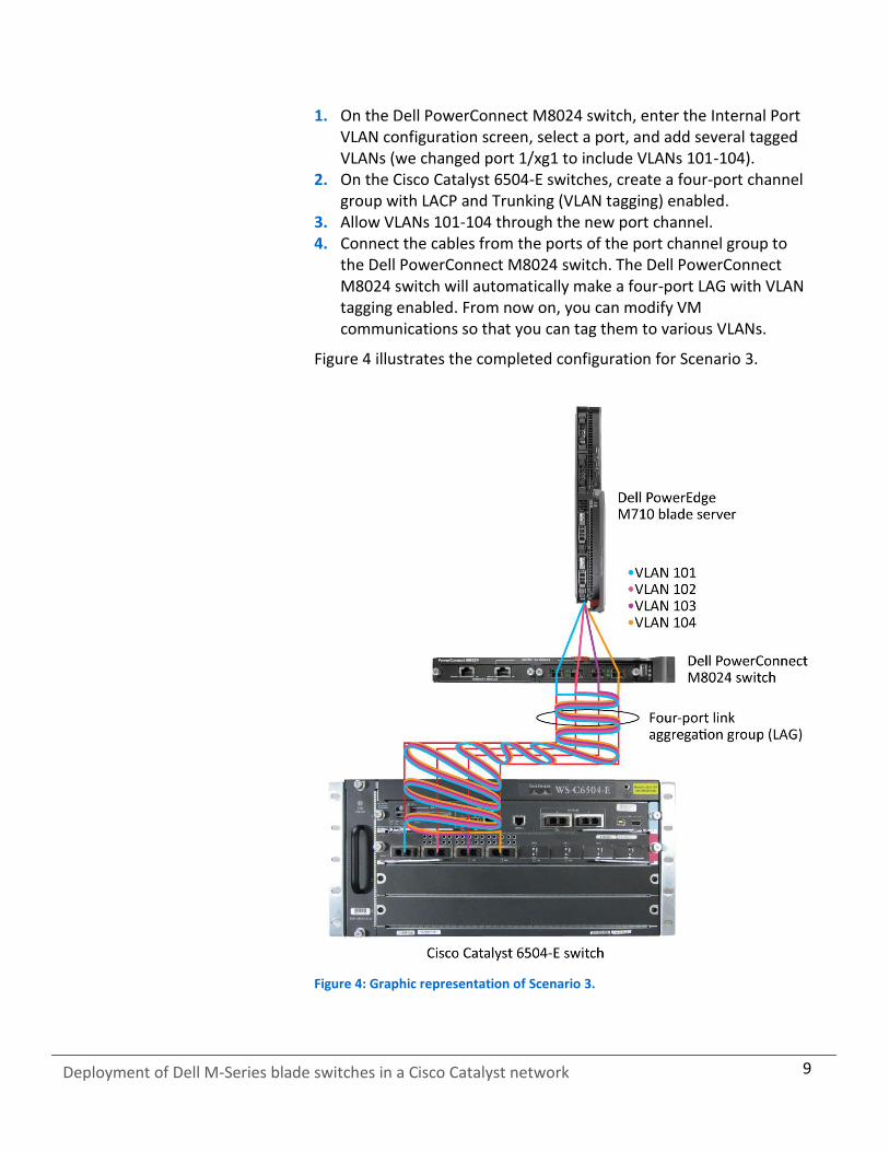
1. On the Dell PowerConnect M8024 switch, enter the Internal Port VLAN configuration screen, select a port, and add several tagged VLANs (we changed port 1/xg1 to include VLANs 101-104).
2. On the Cisco Catalyst 6504-E switches, create a four-port channel group with LACP and Trunking (VLAN tagging) enabled.
3. Allow VLANs 101-104 through the new port channel. 4. Connect the cables from the ports of the port channel group to
the Dell PowerConnect M8024 switch. The Dell PowerConnect M8024 switch will automatically make a four-port LAG with VLAN tagging enabled. From now on, you can modify VM communications so that you can tag them to various VLANs.
Figure 4 illustrates the completed configuration for Scenario 3.
Figure 4: Graphic representation of Scenario 3.
10
Deployment of Dell M-Series blade switches in a Cisco Catalyst network
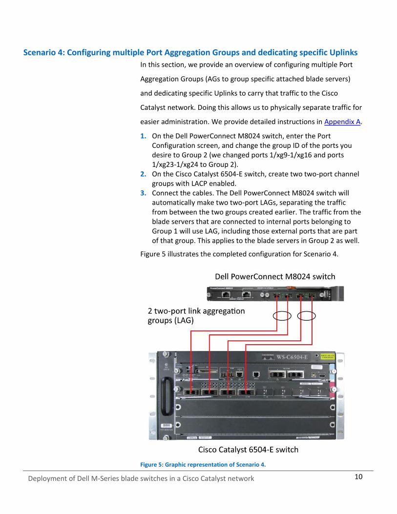
Scenario 4: Configuring multiple Port Aggregation Groups and dedicating specific Uplinks
In this section, we provide an overview of configuring multiple Port
Aggregation Groups (AGs to group specific attached blade servers)
and dedicating specific Uplinks to carry that traffic to the Cisco
Catalyst network. Doing this allows us to physically separate traffic for
easier administration. We provide detailed instructions in Appendix A.
1. On the Dell PowerConnect M8024 switch, enter the Port Configuration screen, and change the group ID of the ports you desire to Group 2 (we changed ports 1/xg9-1/xg16 and ports 1/xg23-1/xg24 to Group 2).
2. On the Cisco Catalyst 6504-E switch, create two two-port channel groups with LACP enabled.
3. Connect the cables. The Dell PowerConnect M8024 switch will automatically make two two-port LAGs, separating the traffic from between the two groups created earlier. The traffic from the blade servers that are connected to internal ports belonging to Group 1 will use LAG, including those external ports that are part of that group. This applies to the blade servers in Group 2 as well.
Figure 5 illustrates the completed configuration for Scenario 4.
Figure 5: Graphic representation of Scenario 4.

11
Deployment of Dell M-Series blade switches in a Cisco Catalyst network
Scenario 5: Adding VLANs in a multi-AG configuration
In this section, we provide an overview of adding VLANs in a multi-AG
configuration, which combine the advantages of virtual network
administration with physical network separation. We provide detailed
instructions in Appendix A.
1. On the Dell PowerConnect M8024 switch, enter the Port Configuration screen, and change the group ID of ports to Group 2 (we changed ports 1/xg9-1/xg16 and ports 1/xg23-1/xg24 to Group 2).
2. Enter the Internal Port VLAN configuration screen, select a port, and add several tagged VLANs (we changed port 1/xg1 to include VLANs 101-102 and port 1/xg9 to include VLANs 103-104).
3. On the Cisco Catalyst 6504-E switches, create two two-port channel groups with LACP enabled. Make sure that the two port channels include the VLANs you configured earlier (we configured VLANs 101-102 for the first port channel and VLANs 103-104 for the second port channel).
4. Connect the cables. The Dell PowerConnect M8024 switch will automatically make two two-port LAGs, separating the traffic from between the two groups created earlier, while allowing for further segregation through VLANs.
Figure 6 illustrates the completed configuration for Scenario 5.

12
Deployment of Dell M-Series blade switches in a Cisco Catalyst network
Figure 6: Graphic representation of Scenario 5.
Scenario 6: Setting up a fully meshed topology
In this section, we provide an overview of setting up a fully meshed
topology while spanning tree protocol (STP) is enabled on an existing
network. STP allows for redundant connections in switches without
creating loops, and the Dell PowerConnect M8024 switches can
automatically integrate themselves into an STP network. The Dell
PowerConnect M8024 in Simple Switch Mode uses LAGs to prevent
loops, but allows Cisco Catalyst switches to handle STP states. We
provide detailed instructions in Appendix A.
1. On the first Cisco Catalyst 6504-E switch, set the spanning tree priority so that it is the root.
2. On the second Cisco Catalyst 6504-E switch, set the spanning tree priority so the tree will default to it as the secondary root in the event of failure.
3. Connect the cables between all switches. The Dell PowerConnect M8024 switches will automatically integrate into the Cisco spanning tree network.
13
Deployment of Dell M-Series blade switches in a Cisco Catalyst network
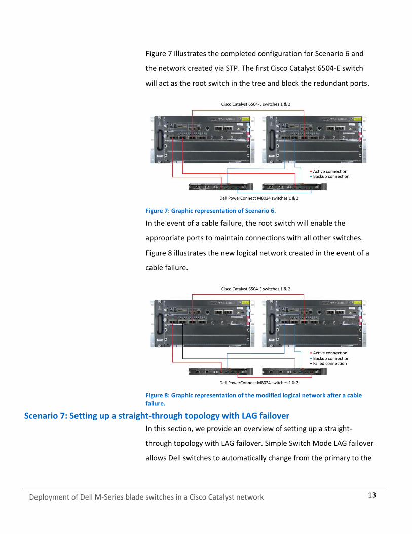
Figure 7 illustrates the completed configuration for Scenario 6 and
the network created via STP. The first Cisco Catalyst 6504-E switch
will act as the root switch in the tree and block the redundant ports.
Figure 7: Graphic representation of Scenario 6.
In the event of a cable failure, the root switch will enable the
appropriate ports to maintain connections with all other switches.
Figure 8 illustrates the new logical network created in the event of a
cable failure.
Figure 8: Graphic representation of the modified logical network after a cable failure.
Scenario 7: Setting up a straight-through topology with LAG failover
In this section, we provide an overview of setting up a straight-
through topology with LAG failover. Simple Switch Mode LAG failover
allows Dell switches to automatically change from the primary to the

14
Deployment of Dell M-Series blade switches in a Cisco Catalyst network
backup LAG in the event of a port failure, reducing potential
downtime. We provide detailed instructions in Appendix A.
1. On the Dell PowerConnect M8024 switch, enter the Port Configuration screen, and change the Lag Role of ports to Secondary (we changed ports 1/xg23-1/xg24 to Secondary).
2. On the Cisco Catalyst 6504-E switches, create two two-port channel groups with LACP enabled.
3. Connect the cables. The Dell PowerConnect M8024 switch will automatically make a two-port LAG with a secondary backup LAG that it will failover to in the event of a cable or port failure.
Figure 9 illustrates the completed configuration for Scenario 7.
Figure 9: Graphic representation of Scenario 7.
Scenario 8: Establishing access with VSS enabled across the Cisco Catalyst 6504-E switches
In this section, we provide an overview of establishing access with
VSS enabled across Cisco Catalyst 6504-E switches. VSS, or Virtual
Switching System, is a Cisco technology that allows multiple switches
to be administered from one switch and present themselves as one
switch, combining link aggregation with switch redundancy. This
15
Deployment of Dell M-Series blade switches in a Cisco Catalyst network
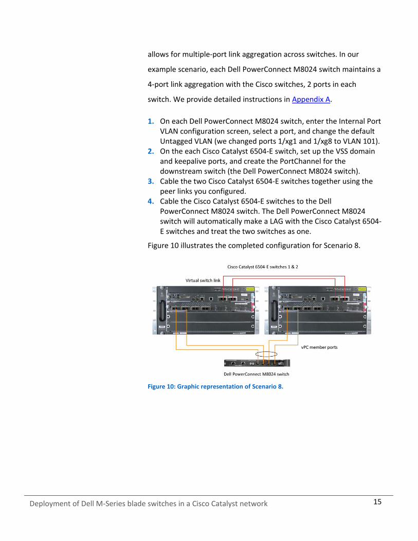
allows for multiple-port link aggregation across switches. In our
example scenario, each Dell PowerConnect M8024 switch maintains a
4-port link aggregation with the Cisco switches, 2 ports in each
switch. We provide detailed instructions in Appendix A.
1. On each Dell PowerConnect M8024 switch, enter the Internal Port VLAN configuration screen, select a port, and change the default Untagged VLAN (we changed ports 1/xg1 and 1/xg8 to VLAN 101).
2. On the each Cisco Catalyst 6504-E switch, set up the VSS domain and keepalive ports, and create the PortChannel for the downstream switch (the Dell PowerConnect M8024 switch).
3. Cable the two Cisco Catalyst 6504-E switches together using the peer links you configured.
4. Cable the Cisco Catalyst 6504-E switches to the Dell PowerConnect M8024 switch. The Dell PowerConnect M8024 switch will automatically make a LAG with the Cisco Catalyst 6504-E switches and treat the two switches as one.
Figure 10 illustrates the completed configuration for Scenario 8.
Figure 10: Graphic representation of Scenario 8.

16
Deployment of Dell M-Series blade switches in a Cisco Catalyst network
APPENDIX A – DETAILED SCENARIO METHODOLOGY
In this appendix, we provide detailed descriptions of the test
scenarios we followed and screenshots for each step, as appropriate.
In each scenario, we assume that the associated switches are at
factory default configurations. For convenience, we’ve included steps
for both the Dell graphical user interface and the command line
interface. The Cisco Catalyst 6504-E graphical user interface for Cisco
IOS 12.2 is basically a Web version of the Cisco command-line
interface, so our Cisco CLI instructions should work fine for the GUI,
as well.
Scenario 1: Plug and play using the Dell PowerConnect M8024 switch for blade deployment into an existing network
On the Dell PowerConnect M8024 switch GUI
1. Log into the switch. 2. Select SystemOperational ModeOperational Mode
Configuration. 3. In the Operational Mode Configuration screen, select Enable in
the Simple Mode drop-down menu, and left-click Apply Changes (see Figure 11).
Figure 11: Simple Mode configuration on the Dell PowerConnect M8024 switch.
On the Dell PowerConnect M8024 switch CLI
1. Log into the switch.
17
Deployment of Dell M-Series blade switches in a Cisco Catalyst network
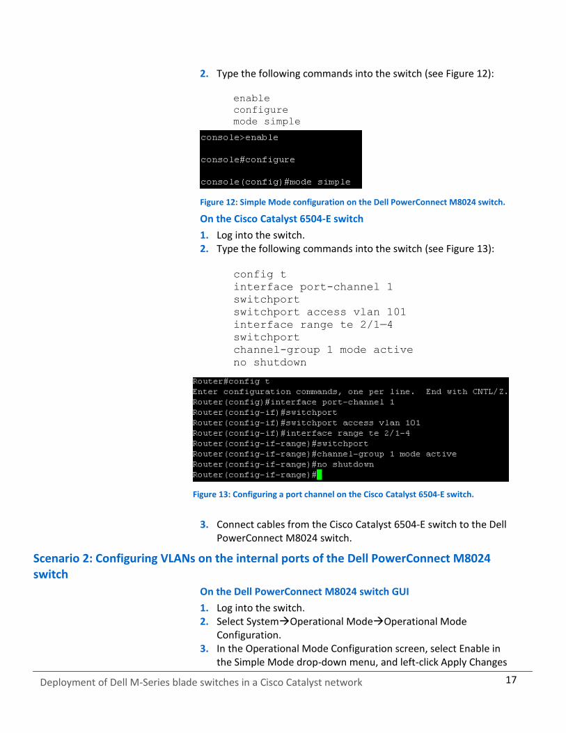
2. Type the following commands into the switch (see Figure 12): enable
configure
mode simple
Figure 12: Simple Mode configuration on the Dell PowerConnect M8024 switch.
On the Cisco Catalyst 6504-E switch
1. Log into the switch. 2. Type the following commands into the switch (see Figure 13):
config t
interface port-channel 1
switchport
switchport access vlan 101
interface range te 2/1—4
switchport
channel-group 1 mode active
no shutdown
Figure 13: Configuring a port channel on the Cisco Catalyst 6504-E switch.
3. Connect cables from the Cisco Catalyst 6504-E switch to the Dell PowerConnect M8024 switch.
Scenario 2: Configuring VLANs on the internal ports of the Dell PowerConnect M8024 switch
On the Dell PowerConnect M8024 switch GUI
1. Log into the switch. 2. Select SystemOperational ModeOperational Mode
Configuration. 3. In the Operational Mode Configuration screen, select Enable in
the Simple Mode drop-down menu, and left-click Apply Changes

18
Deployment of Dell M-Series blade switches in a Cisco Catalyst network
(see Figure 14). The switch will reset after this and you will need to log in again.
Figure 14: Simple Mode configuration on the Dell PowerConnect M8024 switch.
4. Select SwitchingPort AggregatorInternal Port VLAN Configuration.
5. In the Internal-Port drop-down menu, select a port (we chose 1/xg1). (See Figure 15.)
Figure 15: Internal Port VLAN Configuration on the Dell PowerConnect M8024 switch.
6. In the Untagged-VLAN textbox, write a VLAN (we chose 101), and left-click Apply Changes (see Figure 16.)

19
Deployment of Dell M-Series blade switches in a Cisco Catalyst network
Figure 16: Selecting a VLAN in Internal Port VLAN Configuration on the Dell PowerConnect M8024 switch.
On the Dell PowerConnect M8024 switch CLI
1. Log into the switch. 2. Type the following commands into the switch (see Figure 17):
enable
configure
port-aggregator group 1
lacp auto
vlan add 101
end
config
port-aggregator lag-failover
Figure 17: Selecting a VLAN in Internal Port VLAN Configuration on the Dell PowerConnect M8024 switch.
On the Cisco Catalyst 6504-E switch
1. Log into the switch. 2. Type the following commands into the switch (see Figure 18):
20
Deployment of Dell M-Series blade switches in a Cisco Catalyst network
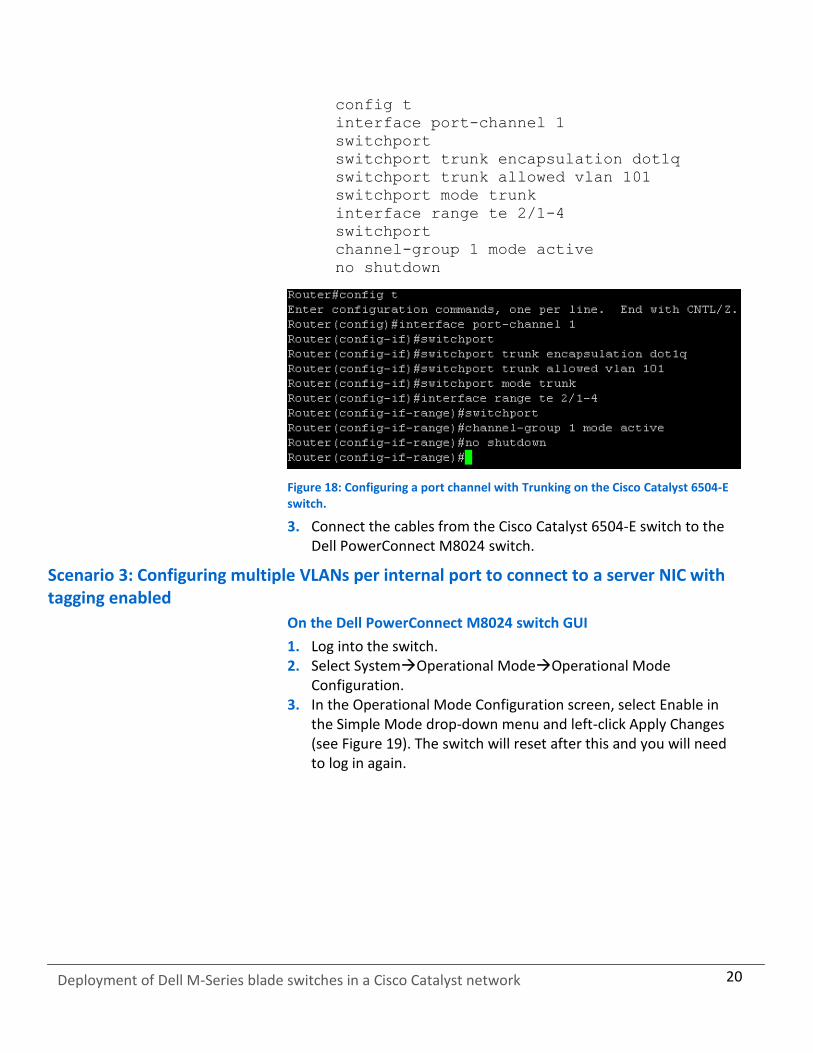
config t
interface port-channel 1
switchport
switchport trunk encapsulation dot1q
switchport trunk allowed vlan 101
switchport mode trunk
interface range te 2/1-4
switchport
channel-group 1 mode active
no shutdown
Figure 18: Configuring a port channel with Trunking on the Cisco Catalyst 6504-E switch.
3. Connect the cables from the Cisco Catalyst 6504-E switch to the Dell PowerConnect M8024 switch.
Scenario 3: Configuring multiple VLANs per internal port to connect to a server NIC with tagging enabled
On the Dell PowerConnect M8024 switch GUI
1. Log into the switch. 2. Select SystemOperational ModeOperational Mode
Configuration. 3. In the Operational Mode Configuration screen, select Enable in
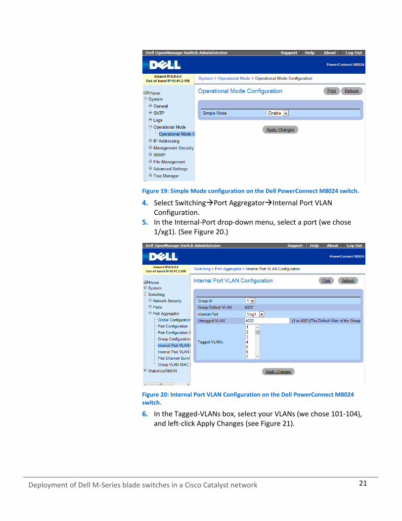
the Simple Mode drop-down menu and left-click Apply Changes (see Figure 19). The switch will reset after this and you will need to log in again.
21
Deployment of Dell M-Series blade switches in a Cisco Catalyst network
Figure 19: Simple Mode configuration on the Dell PowerConnect M8024 switch.
4. Select SwitchingPort AggregatorInternal Port VLAN Configuration.
5. In the Internal-Port drop-down menu, select a port (we chose 1/xg1). (See Figure 20.)
Figure 20: Internal Port VLAN Configuration on the Dell PowerConnect M8024 switch.
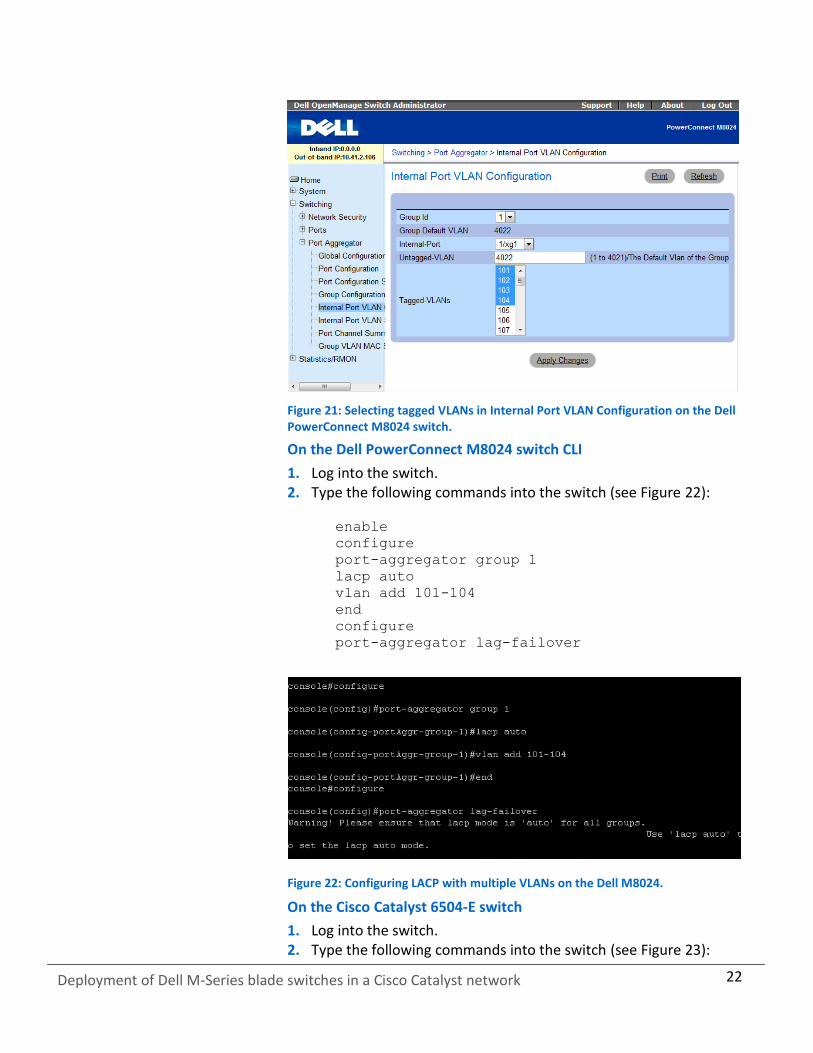
6. In the Tagged-VLANs box, select your VLANs (we chose 101-104), and left-click Apply Changes (see Figure 21).
22
Deployment of Dell M-Series blade switches in a Cisco Catalyst network
Figure 21: Selecting tagged VLANs in Internal Port VLAN Configuration on the Dell PowerConnect M8024 switch.
On the Dell PowerConnect M8024 switch CLI
1. Log into the switch. 2. Type the following commands into the switch (see Figure 22):
enable
configure
port-aggregator group 1
lacp auto
vlan add 101-104
end
configure
port-aggregator lag-failover
Figure 22: Configuring LACP with multiple VLANs on the Dell M8024.
On the Cisco Catalyst 6504-E switch
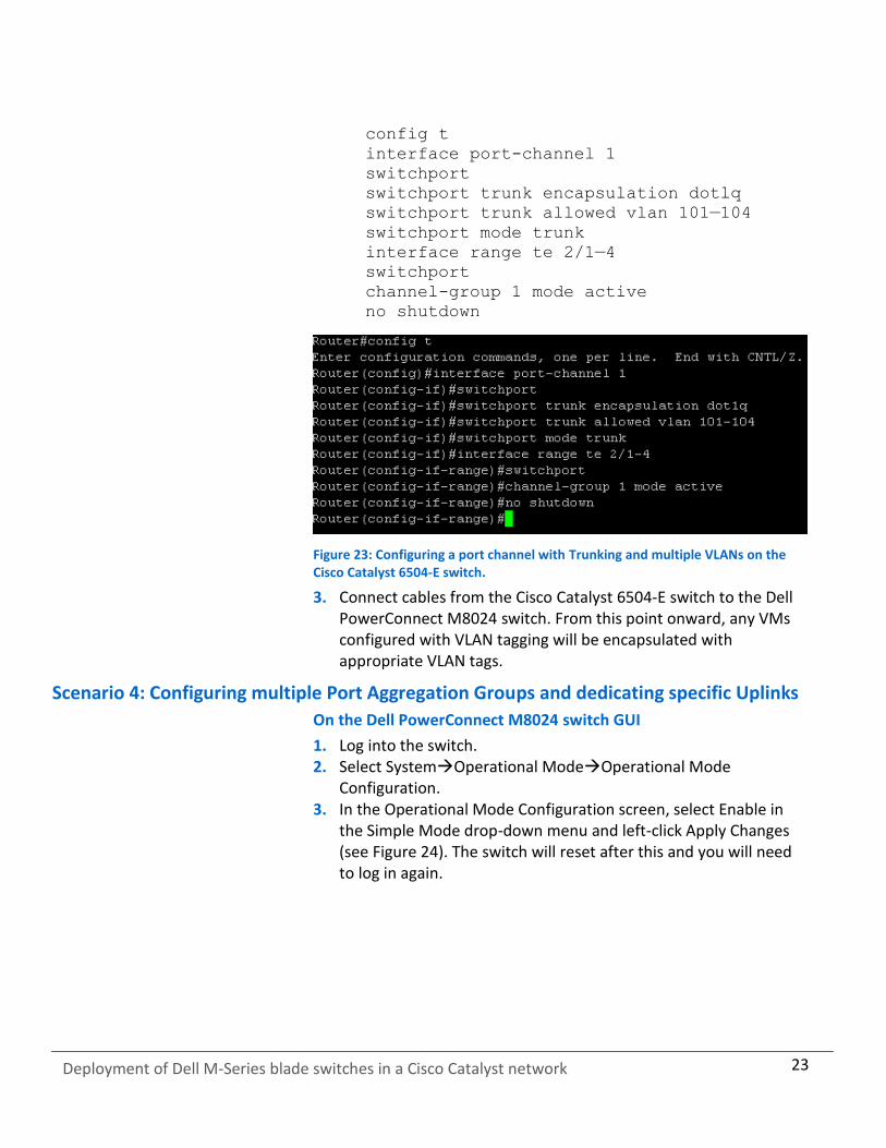
1. Log into the switch. 2. Type the following commands into the switch (see Figure 23):
23
Deployment of Dell M-Series blade switches in a Cisco Catalyst network
config t
interface port-channel 1
switchport
switchport trunk encapsulation dotlq
switchport trunk allowed vlan 101—104
switchport mode trunk
interface range te 2/1—4
switchport
channel-group 1 mode active
no shutdown
Figure 23: Configuring a port channel with Trunking and multiple VLANs on the Cisco Catalyst 6504-E switch.
3. Connect cables from the Cisco Catalyst 6504-E switch to the Dell PowerConnect M8024 switch. From this point onward, any VMs configured with VLAN tagging will be encapsulated with appropriate VLAN tags.
Scenario 4: Configuring multiple Port Aggregation Groups and dedicating specific Uplinks
On the Dell PowerConnect M8024 switch GUI
1. Log into the switch. 2. Select SystemOperational ModeOperational Mode
Configuration. 3. In the Operational Mode Configuration screen, select Enable in
the Simple Mode drop-down menu and left-click Apply Changes (see Figure 24). The switch will reset after this and you will need to log in again.

24
Deployment of Dell M-Series blade switches in a Cisco Catalyst network
Figure 24: Simple Mode configuration on the Dell PowerConnect M8024 switch.
4. Select SwitchingPort Aggregator Port Configuration (see Figure 25).
Figure 25: The Port Configuration screen on the Dell PowerConnect M8024 switch.
5. In the Port Configuration screen, change the Group ID of the internal ports (we changed ports 9-16 to Group 2). (See Figure 26.)

25
Deployment of Dell M-Series blade switches in a Cisco Catalyst network
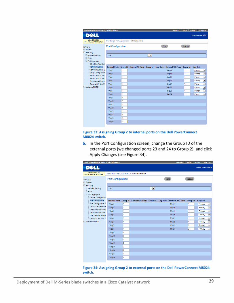
Figure 26: Assigning Group 2 to internal ports on the Dell PowerConnect M8024 switch.
6. In the Port Configuration screen, change the Group ID of the external ports (we changed ports 23 and 24 to Group 2), and click Apply Changes (see Figure 27).
Figure 27: Assigning Group 2 to external ports on the Dell PowerConnect M8024 switch.

26
Deployment of Dell M-Series blade switches in a Cisco Catalyst network
On the Dell PowerConnect M8024 switch CLI
1. Log into the switch. 2. Type the following commands into the switch (see Figure 28):
configure
port-aggregator group 1
no add ethernet 1/xg9—1/xgl6, 1/xg23—1/xg24
add ethernet 1/xg9—1/xgl6, 1/xg23—1/xg24
end
Figure 28: Moving ports from aggregate group 1 to aggregate group 2 on the Dell PowerConnect M8024 switch.
On the Cisco Catalyst 6504-E switch
1. Log into the switch. 2. Type the following commands into the switch to configure the
port channels (see Figure 29):
config t
interface port-channel 1
switchport
switchport access vlan 101
interface port-channel 2
switchport
switchport access vlan 102
Figure 29: Configuring the port channels on the Cisco Catalyst 6504-E switch.
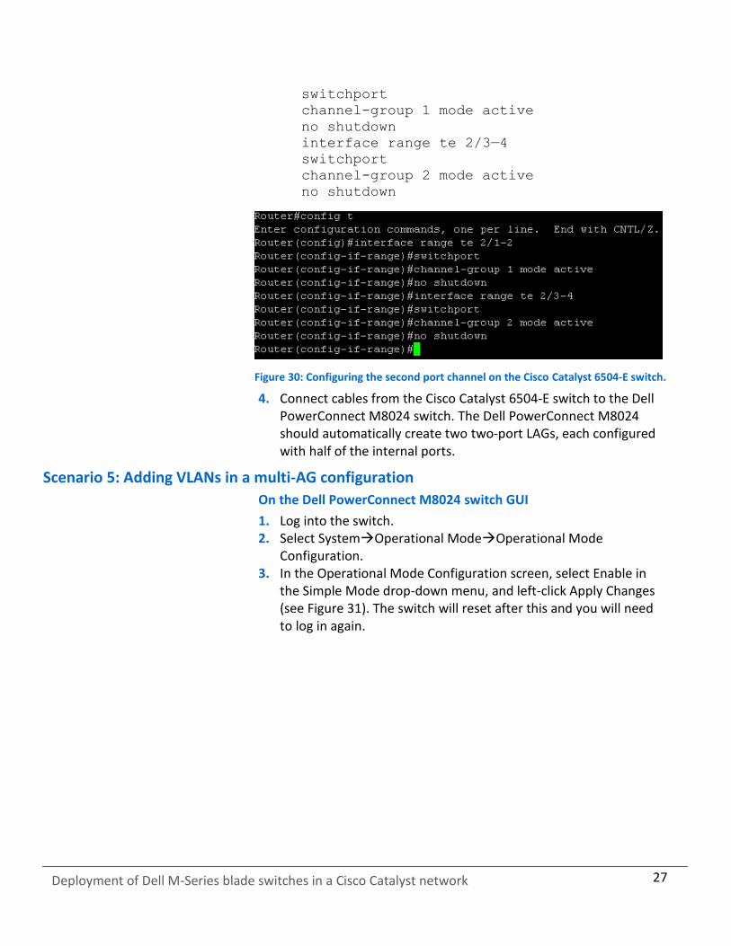
3. Type the following commands into the switch to add the port channels to the ports (see Figure 30):
config t
interface range te 2/1—2
27
Deployment of Dell M-Series blade switches in a Cisco Catalyst network
switchport
channel-group 1 mode active
no shutdown
interface range te 2/3—4
switchport
channel-group 2 mode active
no shutdown
Figure 30: Configuring the second port channel on the Cisco Catalyst 6504-E switch.
4. Connect cables from the Cisco Catalyst 6504-E switch to the Dell PowerConnect M8024 switch. The Dell PowerConnect M8024 should automatically create two two-port LAGs, each configured with half of the internal ports.
Scenario 5: Adding VLANs in a multi-AG configuration
On the Dell PowerConnect M8024 switch GUI
1. Log into the switch. 2. Select SystemOperational ModeOperational Mode
Configuration. 3. In the Operational Mode Configuration screen, select Enable in
the Simple Mode drop-down menu, and left-click Apply Changes (see Figure 31). The switch will reset after this and you will need to log in again.

28
Deployment of Dell M-Series blade switches in a Cisco Catalyst network
Figure 31: Simple Mode configuration on the Dell PowerConnect M8024 switch.
4. Select SwitchingPort AggregatorPort Configuration (see Figure 32).
Figure 32: The Port Configuration screen on the Dell PowerConnect M8024 switch.
5. In the Port Configuration screen, change the Group ID of the internal ports (we changed ports 9 through 16 to Group 2). (See Figure 33.)
29
Deployment of Dell M-Series blade switches in a Cisco Catalyst network
Figure 33: Assigning Group 2 to internal ports on the Dell PowerConnect M8024 switch.
6. In the Port Configuration screen, change the Group ID of the external ports (we changed ports 23 and 24 to Group 2), and click Apply Changes (see Figure 34).
Figure 34: Assigning Group 2 to external ports on the Dell PowerConnect M8024 switch.

30
Deployment of Dell M-Series blade switches in a Cisco Catalyst network
7. Select SwitchingPort AggregatorInternal Port VLAN Configuration (see Figure 35).
Figure 35: Internal Port VLAN Configuration on the Dell PowerConnect M8024 switch.
8. In the Internal Port drop-down menu, select a port (we chose 1/xg1).
9. In the Tagged-VLANs box, select your VLANs (we chose 101-102), and left-click Apply Changes (see Figure 36).
Figure 36: Selecting VLANs for the first port in Internal Port VLAN Configuration on the Dell PowerConnect M8024 switch.

31
Deployment of Dell M-Series blade switches in a Cisco Catalyst network
10. Repeat Step 9, applying VLANs 103-104 to port 1/xg9, (see Figure 37).
Figure 37: Selecting VLANs for the second port in Internal Port VLAN Configuration on the Dell PowerConnect M8024 switch.
On the Dell PowerConnect M8024 switch CLI
1. Log into the switch. 2. Type the following commands into the switch (see Figure 38):
configure
port-aggregator group 1
no add ethernet 1/xg9-1/xg16, 1/xg23-1/xg24
interface ethernet 1/xg1
switchport general allowed vlan add 101-102
port-aggregator group 2
add ethernet 1/xg9-1/xg16, 1/xg23-1/xg24
interface ethernet 1/xg9
switchport general allowed vlan add 103-104
Figure 38: Moving ports from aggregate group 1 to aggregate group 2.
32
Deployment of Dell M-Series blade switches in a Cisco Catalyst network
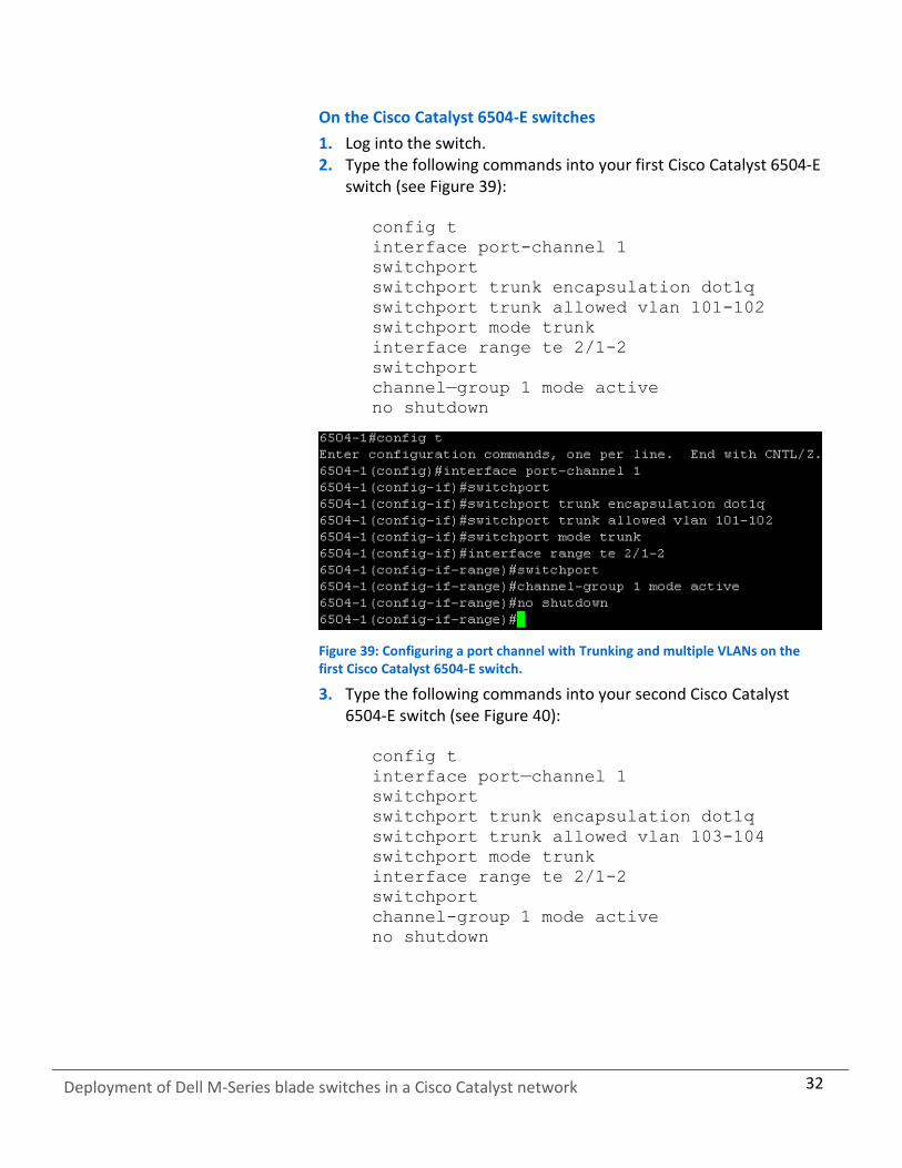
On the Cisco Catalyst 6504-E switches
1. Log into the switch. 2. Type the following commands into your first Cisco Catalyst 6504-E
switch (see Figure 39):
config t
interface port-channel 1
switchport
switchport trunk encapsulation dot1q
switchport trunk allowed vlan 101-102
switchport mode trunk
interface range te 2/1-2
switchport
channel—group 1 mode active
no shutdown
Figure 39: Configuring a port channel with Trunking and multiple VLANs on the first Cisco Catalyst 6504-E switch.
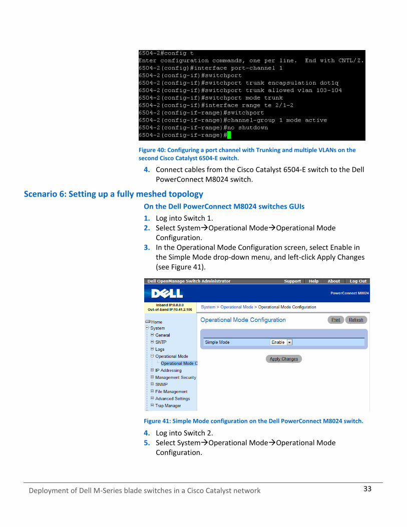
3. Type the following commands into your second Cisco Catalyst 6504-E switch (see Figure 40):
config t
interface port—channel 1
switchport
switchport trunk encapsulation dot1q
switchport trunk allowed vlan 103-104
switchport mode trunk
interface range te 2/1-2
switchport
channel-group 1 mode active
no shutdown
33
Deployment of Dell M-Series blade switches in a Cisco Catalyst network
Figure 40: Configuring a port channel with Trunking and multiple VLANs on the second Cisco Catalyst 6504-E switch.
4. Connect cables from the Cisco Catalyst 6504-E switch to the Dell PowerConnect M8024 switch.
Scenario 6: Setting up a fully meshed topology
On the Dell PowerConnect M8024 switches GUIs
1. Log into Switch 1. 2. Select SystemOperational ModeOperational Mode
Configuration. 3. In the Operational Mode Configuration screen, select Enable in
the Simple Mode drop-down menu, and left-click Apply Changes (see Figure 41).
Figure 41: Simple Mode configuration on the Dell PowerConnect M8024 switch.
4. Log into Switch 2. 5. Select SystemOperational ModeOperational Mode
Configuration.
34
Deployment of Dell M-Series blade switches in a Cisco Catalyst network
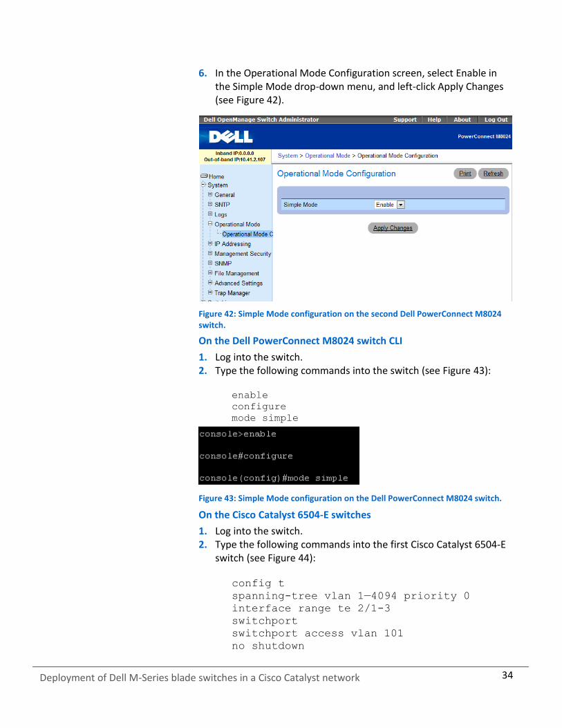
6. In the Operational Mode Configuration screen, select Enable in the Simple Mode drop-down menu, and left-click Apply Changes (see Figure 42).
Figure 42: Simple Mode configuration on the second Dell PowerConnect M8024 switch.
On the Dell PowerConnect M8024 switch CLI
1. Log into the switch. 2. Type the following commands into the switch (see Figure 43):
enable
configure
mode simple
Figure 43: Simple Mode configuration on the Dell PowerConnect M8024 switch.
On the Cisco Catalyst 6504-E switches
1. Log into the switch. 2. Type the following commands into the first Cisco Catalyst 6504-E
switch (see Figure 44):
config t
spanning-tree vlan 1—4094 priority 0
interface range te 2/1-3
switchport
switchport access vlan 101
no shutdown

35
Deployment of Dell M-Series blade switches in a Cisco Catalyst network
Figure 44: Configuring spanning tree priority on the first Cisco Catalyst 6504-E switch.
3. Type the following commands into the second Cisco Catalyst 6504-E switch (see Figure 45):
config t
spanning-tree vlan 1-4094 priority 4096
interface range te 2/1-3
switchport
switchport access vlan 101
no shutdown
Figure 45: Configuring spanning tree priority on the second Cisco Catalyst 6504-E switch.
4. Connect the cables from the Cisco Catalyst 6504-E switches to each other and to the Dell PowerConnect M8024 switches. The switches will deliberate amongst themselves and create a spanning tree with the first Cisco switch as the root.
Scenario 7: Setting up a straight-through topology with LAG failover
On the Dell PowerConnect M8024 switch
1. Log into the switch. 2. Select SystemOperational ModeOperational Mode
Configuration. 3. In the Operational Mode Configuration screen, select Enable in
the Simple Mode drop-down menu, and left-click Apply Changes (see Figure 46). The switch will reset after this and you will need to log in again.

36
Deployment of Dell M-Series blade switches in a Cisco Catalyst network
Figure 46: Simple Mode configuration on the Dell PowerConnect M8024 switch.
4. Select SwitchingPort AggregatorPort Configuration (see Figure 47).
Figure 47: The Port Configuration screen on the Dell PowerConnect M8024 switch.
5. In the Port Configuration screen, change the Lag Role of the external ports (we changed ports 23 and 24 to Secondary), and click Apply Changes (see Figure 48).

37
Deployment of Dell M-Series blade switches in a Cisco Catalyst network
Figure 48: Assigning a Secondary LAG to external ports on the Dell PowerConnect M8024 switch.
On the Dell PowerConnect M8024 switch CLI
1. Log into the switch. 2. Type the following commands into the switch (see Figure 49):
configure
port-aggregator group 1
no add ethernet 1/xg23-1/xg24
add ethernet 1/xg23-1/xg24
exit
Figure 49: Simple Mode configuration on the Dell PowerConnect M8024 switch.
On the Cisco Catalyst 6504-E switch
1. Log into the switch. 2. Assuming that you configured the Dell PowerConnect M8024 with
three different groups, type the following commands into the switch (see Figure 50):

38
Deployment of Dell M-Series blade switches in a Cisco Catalyst network
config t
interface port—channel 1
switchport
switchport access vlan 101
interface port—channel 2
switchport
switchport access vlan 101
interface range te 2/1—2
switchport
channel—group 1 mode active
no shutdown
interface range te 2/3—4
switchport
channel—group 2 mode active
no shutdown
Figure 50: Configuring two port channels on the Cisco Catalyst 6504-E switch.
3. Connect cables from the Cisco Catalyst 6504-E switch to the Dell PowerConnect M8024 switch. The Dell PowerConnect M8024 should automatically create one two-port LAG with a two-port backup in case of cable or port failure.
Scenario 8: Establishing access with VSS enabled across the Cisco Catalyst 6504-E switches
On the Dell PowerConnect M8024 switch
1. Log into the switch. 2. Select SystemOperational ModeOperational Mode
Configuration. 3. In the Operational Mode Configuration screen, select Enable in
the Simple Mode drop-down menu, and left-click Apply Changes (see Figure 51). The switch will reset after this and you will need to log in again.

39
Deployment of Dell M-Series blade switches in a Cisco Catalyst network
Figure 51: Simple Mode configuration on the Dell PowerConnect M8024 switch.
4. Select SwitchingPort AggregatorInternal Port VLAN Configuration.
5. In the Internal-Port drop-down menu, select a port (we chose 1/xg1). (See Figure 52.)
Figure 52: Internal Port VLAN Configuration on the Dell PowerConnect M8024 switch.
6. In the Untagged-VLAN textbox, write a VLAN (we chose 101), and left-click Apply Changes (see Figure 53).

40
Deployment of Dell M-Series blade switches in a Cisco Catalyst network
Figure 53: Selecting a VLAN in Internal Port VLAN Configuration on the Dell PowerConnect M8024 switch.
On the Dell PowerConnect M8024 switch CLI
1. Log into the switch. 2. Type the following commands into the switch (see Figure 54):
enable
configure
mode simple
Figure 54: Simple Mode configuration on the Dell PowerConnect M8024 switch.
On the Cisco Catalyst 6504-E switch
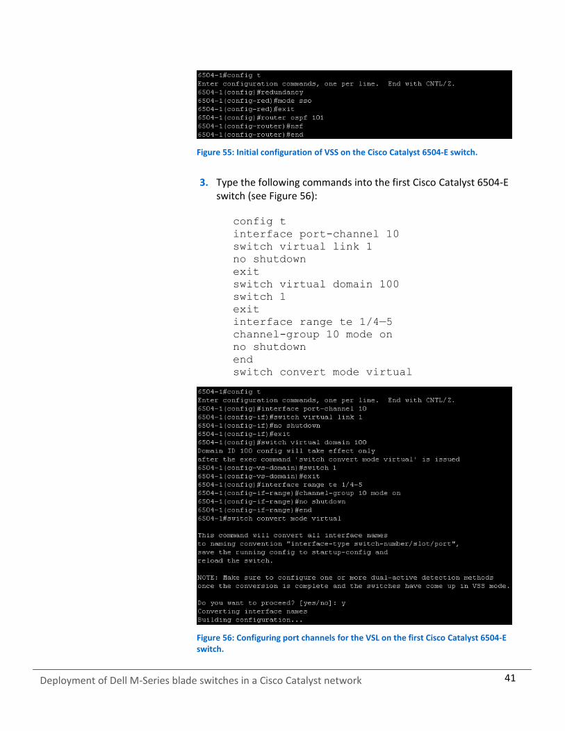
1. Log into the switch. 2. Type the following commands into the first Cisco Catalyst 6504-E
switch (see Figure 55):
config t
redundancy
mode sso
exit
router ospf 101
nsf
end
41
Deployment of Dell M-Series blade switches in a Cisco Catalyst network
Figure 55: Initial configuration of VSS on the Cisco Catalyst 6504-E switch.
3. Type the following commands into the first Cisco Catalyst 6504-E
switch (see Figure 56):
config t
interface port-channel 10
switch virtual link 1
no shutdown
exit
switch virtual domain 100
switch 1
exit
interface range te 1/4—5
channel-group 10 mode on
no shutdown
end
switch convert mode virtual
Figure 56: Configuring port channels for the VSL on the first Cisco Catalyst 6504-E switch.
42
Deployment of Dell M-Series blade switches in a Cisco Catalyst network
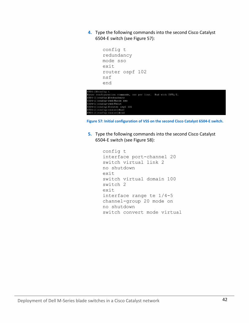
4. Type the following commands into the second Cisco Catalyst 6504-E switch (see Figure 57):
config t
redundancy
mode sso
exit
router ospf 102
nsf
end
Figure 57: Initial configuration of VSS on the second Cisco Catalyst 6504-E switch.
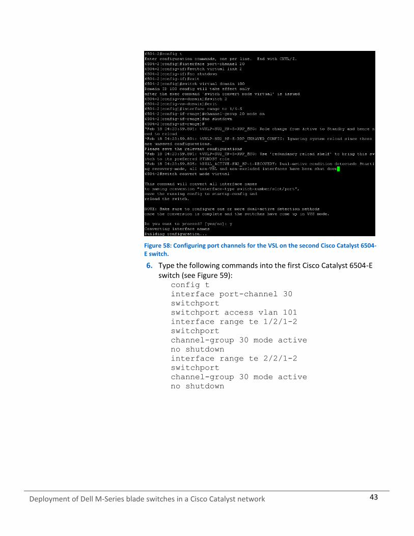
5. Type the following commands into the second Cisco Catalyst 6504-E switch (see Figure 58):
config t
interface port-channel 20
switch virtual link 2
no shutdown
exit
switch virtual domain 100
switch 2
exit
interface range te 1/4-5
channel-group 20 mode on
no shutdown
switch convert mode virtual
43
Deployment of Dell M-Series blade switches in a Cisco Catalyst network
Figure 58: Configuring port channels for the VSL on the second Cisco Catalyst 6504-E switch.
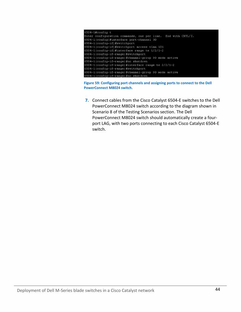
6. Type the following commands into the first Cisco Catalyst 6504-E switch (see Figure 59):
config t
interface port-channel 30
switchport
switchport access vlan 101
interface range te 1/2/1-2
switchport
channel-group 30 mode active
no shutdown
interface range te 2/2/1-2
switchport
channel-group 30 mode active
no shutdown
44
Deployment of Dell M-Series blade switches in a Cisco Catalyst network
Figure 59: Configuring port channels and assigning ports to connect to the Dell PowerConnect M8024 switch.
7. Connect cables from the Cisco Catalyst 6504-E switches to the Dell
PowerConnect M8024 switch according to the diagram shown in Scenario 8 of the Testing Scenarios section. The Dell PowerConnect M8024 switch should automatically create a four-port LAG, with two ports connecting to each Cisco Catalyst 6504-E switch.
45
Deployment of Dell M-Series blade switches in a Cisco Catalyst network
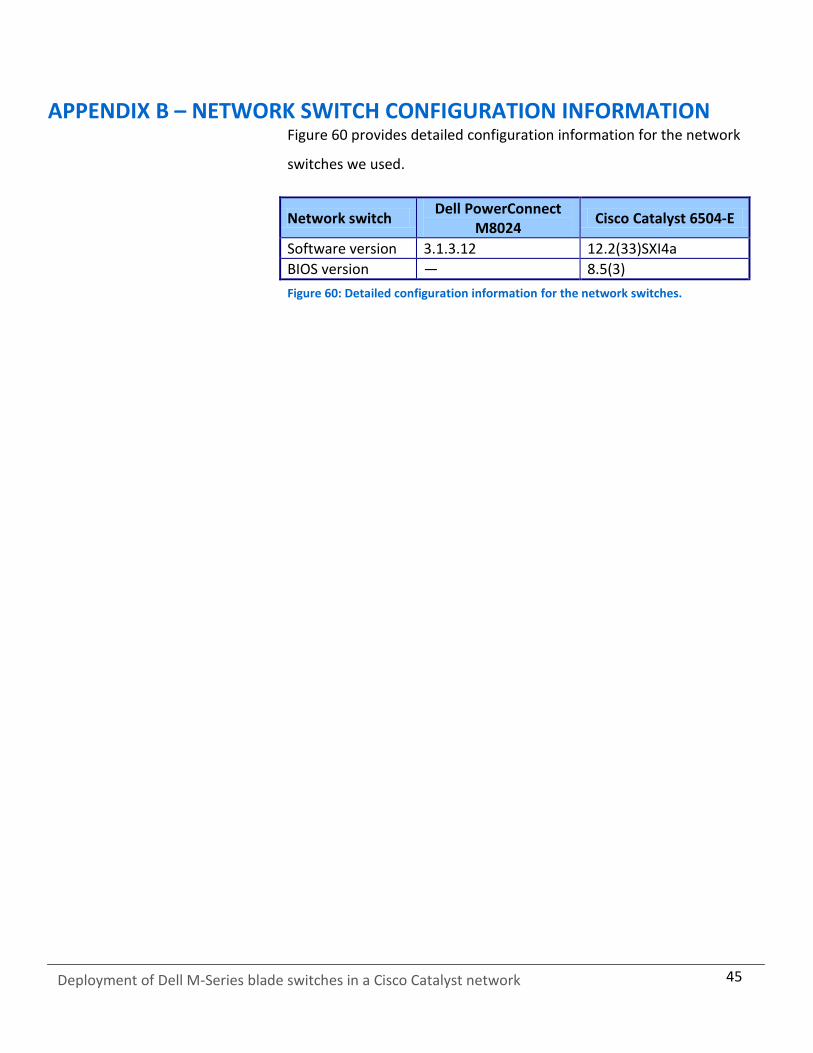
APPENDIX B – NETWORK SWITCH CONFIGURATION INFORMATION Figure 60 provides detailed configuration information for the network
switches we used.
Network switch Dell PowerConnect
M8024 Cisco Catalyst 6504-E
Software version 3.1.3.12 12.2(33)SXI4a
BIOS version — 8.5(3)
Figure 60: Detailed configuration information for the network switches.
46
Deployment of Dell M-Series blade switches in a Cisco Catalyst network
ABOUT PRINCIPLED TECHNOLOGIES
We provide industry-leading technology assessment and fact-based marketing services. We bring to every assignment extensive experience with and expertise in all aspects of technology testing and analysis, from researching new technologies, to developing new methodologies, to testing with existing and new tools.
When the assessment is complete, we know how to present the results to a broad range of target audiences. We provide our clients with the materials they need, from market-focused data to use in their own collateral to custom sales aids, such as test reports, performance assessments, and white papers. Every document reflects the results of our trusted independent analysis.
We provide customized services that focus on our clients’ individual requirements. Whether the technology involves hardware, software, Web sites, or services, we offer the experience, expertise, and tools to help our clients assess how it will fare against its competition, its performance, its market readiness, and its quality and reliability.
Our founders, Mark L. Van Name and Bill Catchings, have worked together in technology assessment for over 20 years. As journalists, they published over a thousand articles on a wide array of technology subjects. They created and led the Ziff-Davis Benchmark Operation, which developed such industry-standard benchmarks as Ziff Davis Media’s Winstone and WebBench. They founded and led eTesting Labs, and after the acquisition of that company by Lionbridge Technologies were the head and CTO of VeriTest.
Principled Technologies, Inc. 1007 Slater Road, Suite 300 Durham, NC, 27703 www.principledtechnologies.com
Principled Technologies is a registered trademark of Principled Technologies, Inc. All other product names are the trademarks of their respective owners.
Disclaimer of Warranties; Limitation of Liability: PRINCIPLED TECHNOLOGIES, INC. HAS MADE REASONABLE EFFORTS TO ENSURE THE ACCURACY AND VALIDITY OF ITS TESTING, HOWEVER, PRINCIPLED TECHNOLOGIES, INC. SPECIFICALLY DISCLAIMS ANY WARRANTY, EXPRESSED OR IMPLIED, RELATING TO THE TEST RESULTS AND ANALYSIS, THEIR ACCURACY, COMPLETENESS OR QUALITY, INCLUDING ANY IMPLIED WARRANTY OF FITNESS FOR ANY PARTICULAR PURPOSE. ALL PERSONS OR ENTITIES RELYING ON THE RESULTS OF ANY TESTING DO SO AT THEIR OWN RISK, AND AGREE THAT PRINCIPLED TECHNOLOGIES, INC., ITS EMPLOYEES AND ITS SUBCONTRACTORS SHALL HAVE NO LIABILITY WHATSOEVER FROM ANY CLAIM OF LOSS OR DAMAGE ON ACCOUNT OF ANY ALLEGED ERROR OR DEFECT IN ANY TESTING PROCEDURE OR RESULT. IN NO EVENT SHALL PRINCIPLED TECHNOLOGIES, INC. BE LIABLE FOR INDIRECT, SPECIAL, INCIDENTAL, OR CONSEQUENTIAL DAMAGES IN CONNECTION WITH ITS TESTING, EVEN IF ADVISED OF THE POSSIBILITY OF SUCH DAMAGES. IN NO EVENT SHALL PRINCIPLED TECHNOLOGIES, INC.’S LIABILITY, INCLUDING FOR DIRECT DAMAGES, EXCEED THE AMOUNTS PAID IN CONNECTION WITH PRINCIPLED TECHNOLOGIES, INC.’S TESTING. CUSTOMER’S SOLE AND EXCLUSIVE REMEDIES ARE AS SET FORTH HEREIN.