A Presentation created - Edutalks.org 8086.pdf · A Presentation created By ... Stack pointer...
26
© Ramesh.K Press Ctrl+l for full screen view
Transcript of A Presentation created - Edutalks.org 8086.pdf · A Presentation created By ... Stack pointer...
© Ramesh.K
Press Ctrl+l for full screen view
www.edutalks.org

A
Presentation
created
By
Ramesh.K
© Ramesh.K
Press Ctrl+l for full screen view
www.edutalks.org

A Microprocessor is a multipurpose, programmable logic device
A Programmable machine
Microprocessor
Memory
IO
A MicroprocessorA MicroprocessorA Microprocessor multipurposeA Microprocessor
that reads binary instructions from a storage device calledreads binary instructionsreads binary instructionsreads binary instructionsreads binary instructionsreads binary instructionsreads binary instructionsreads binary instructions from a storage device calledfrom a storage device calledreads binary instructions from a storage device calledfrom a storage device calledfrom a storage device called
memory, accepts binary data as inputs and processes datainputs andinputs and processes dataprocesses data
according to those instructions, and provides results as output.
© Ramesh.K
www.edutalks.orgwww.edutalks.org

• It is a 16-bit μp. • 8086 has a 20 bit address bus
can access up to 220 memory locations (1 MB).
• It can support up to 64K I/O ports.
• It provides 14, 16 -bit registers. • It has multiplexed address
and data bus AD0- AD15 and A16 – A19.
• It requires single phase clock with33% duty cycle to provide internaltiming.
• 8086 is designed to operate in twomodes, Minimum and Maximum.
• It can prefetches upto 6 instructionbytes from memory and queues themin order to speed up instructionexecution.
• It requires +5V power supply.• A 40 pin dual in line package
© Ramesh.K
www.edutalks.orgwww.edutalks.orgwww.edutalks.orgwww.edutalks.org

© Ramesh.K
www.edutalks.org

Internal Architecture of 8086 Internal Architecture of 8086
• 8086 has two blocks BIU and EU. • The BIU performs all bus operations such as instruction fetching,
reading and writing operands for memory and calculating the addresses of the memory operands. The instruction bytes are transferred to the instruction queue.
• EU executes instructions from the instruction system byte queue. • Both units operate asynchronously to give the 8086 an overlapping
instruction fetch and execution mechanism which is called as Pipelining. This results in efficient use of the system bus and system performance.
• BIU contains Instruction queue, Segment registers, Instruction pointer, Address adder.
• EU contains Control circuitry, Instruction decoder, ALU, Pointer and Index register, Flag register. © Ramesh.K
www.edutalks.org

EXCECUTION UNIT
Decodes instructions fetched by the BIUGenerate control signals,Executes instructions.The main parts areControl CircuitryInstruction decoderALU
© Ramesh.K
www.edutalks.org

Normally used for storingtemporary results
Each of the registers is 16 bitswide (AX, BX, CX, DX)
Can be accessed as either 16 or 8bits AX, AH, AL
AH AL
BH BL
CH CL
DH DL
SP
BP
SI
DI
AX
BX
DX
CX
Accumulator
Base
Data
Count
DX
Pointer
Index
Base pointer
Stack pointer
Source Index
Destination Index
8 bit 8 bit16 bit
EXCECUTION UNIT-General Purpose Registers
© Ramesh.K
www.edutalks.orgwww.edutalks.org

Register Purpose
AX Word multiply, word divide, word I /O
AL Byte multiply, byte divide, byte I/O, decimal arithmetic
AH Byte multiply, byte divide
BX Store address information
CX String operation, loops
CL Variable shift and rotate
DX Word multiply, word divide, indirect I/O
EXCECUTION UNIT-General Purpose Registers
© Ramesh.K
www.edutalks.orgwww.edutalks.org

Pointer And Index Registers
used to keep offset addresses.Used in various forms of memory addressing. In the case of SP and BP the default reference to form a physical
address is the Stack Segment(SS-will be discussed under the BIU) The index registers (SI & Di) and the BX generally default to the Data
segment register(DS).
• SP: Stack pointer– Used with SS to access the stack segment
• BP: Base Pointer– Primarily used to access data on the stack– Can be used to access data in other segments
© Ramesh.K
www.edutalks.org

• SI: Source Index register– is required for some string operations– When string operations are performed, the SI register points to
memory locations in the data segment which is addressed by the DS register. Thus, SI is associated with the DS in string operations.
• DI: Destination Index register– is also required for some string operations.– When string operations are performed, the DI register points to
memory locations in the data segment which is addressed by the ES register. Thus, DI is associated with the ES in string operations.
• The SI and the DI registers may also be used to access data stored in arrays
© Ramesh.K
www.edutalks.org

EXCECUTION UNIT-Flag register
A flag is a flip flop which indicates some conditions produced by the execution of an instruction or controls certain operation of the EU .In 8086 The EU contains a 16 bit flag register9 of the 16 are active flags and remaining 7 are undefined.
6 flags indicates some conditions- status flags3 flags –control Flags
U U U U OF DF IF TF SF ZF U AF U PF U CF15 14 13 12 11 10 9 8 7 6 5 4 3 2 1 0
CarryParityAuxiliaryZeroTrap
Interrupt
DirectionOver flow
Sign
PF
ParityParity
AF
Auxiliary
AF
Auxiliary
ZF
ZeroZero
SF
Sign ZeroSign ZeroSignSign
TF
TrapTrap
IF15 14 13 12 11 10 9 8 7 6 5 4 3 2 1 015 14 13 12 11 10 9 8 7 6 5 4 3 2 1 015 14 13 12 11 10 9 8 7 6 5 4 3 2 1 015 14 13 12 11 10 9 8 7 6 5 4 3 2 1 015 14 13 12 11 10 9 8 7 6 5 4 3 2 1 015 14 13 12 11 10 9 8 7 6 5 4 3 2 1 0
Interrupt
15 14 13 12 11 10 9 8 7 6 5 4 3 2 1 015 14 13 12 11 10 9 8 7 6 5 4 3 2 1 015 14 13 12 11 10 9 8 7 6 5 4 3 2 1 015 14 13 12 11 10 9 8 7 6 5 4 3 2 1 0
Interrupt
DF
DirectionDirection
U OF
DirectionOver flowOver flow
CF
CarryCarry
© Ramesh.K
www.edutalks.orgwww.edutalks.orgwww.edutalks.orgwww.edutalks.orgwww.edutalks.org

EXCECUTION UNIT-Flag register
Flag Purpose
Carry (CF) Holds the carry after addition or the borrow after subtraction. Also indicates some error conditions, as dictated by some programs and procedures .
Parity(PF) PF=0;odd parity ,PF=1;even parity.
Auxiliary (AF) Holds the carry(half – carry) after addition or borrow aftersubtraction between bit positions 3 and 4 of the result (for example,in BCD addition or subtraction.)
Zero (ZF) Shows the result of the arithmetic or logic operation.Z=1;result is zero. Z=0; The result is 0
Sign (SF) Holds the sign of the result after an arithmetic/logic instructionexecution. S=1;negative,S=0;positive© Ramesh.K
www.edutalks.orgwww.edutalks.orgwww.edutalks.orgwww.edutalks.orgwww.edutalks.org

EXCECUTION UNIT-Flag register
Flag Purpose
Trap(TF) A control flag.Enables the trapping through an on-chip debugging feature.
Interrupt (IF) A control flag.Controls the operation of the INTR (interrupt request)I=0;INTR pin disabled. I=1;INTR pin enabled.
Direction(DF) A control flag.It selects either the increment or decrement mode for DI and /or SIregisters during the string instructions.
Overflow (OF) Overflow occurs when signed numbers are added or subtracted.An overflow indicates the result has exceeded the capacity of themachine
© Ramesh.K
www.edutalks.orgwww.edutalks.orgwww.edutalks.orgwww.edutalks.orgwww.edutalks.org

• Six of the flags are status indicators reflecting properties of the last arithmetic or logical instruction.
• For example, if register AL = 7Fh and the instruction ADD AL,1 is executed then the following happen
AL = 80hCF = 0; there is no carry out of bit 7PF = 0; 80h has an odd number of onesAF = 1; there is a carry out of bit 3 into bit 4ZF = 0; the result is not zeroSF = 1; bit seven is oneOF = 1; the sign bit has changedCan be used to transfer program control to a new memory location;for example: ADD AL,1
JNZ 0100h
EXCECUTION UNIT-Flag register
© Ramesh.K
www.edutalks.orgwww.edutalks.orgwww.edutalks.orgwww.edutalks.orgwww.edutalks.org

BUS INTERFACE UNIT (BIU)
© Ramesh.K
www.edutalks.org
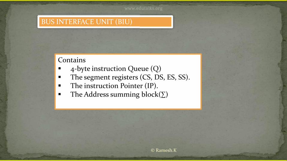
BUS INTERFACE UNIT (BIU)
Contains 4-byte instruction Queue (Q) The segment registers (CS, DS, ES, SS). The instruction Pointer (IP). The Address summing block(∑)
© Ramesh.K
www.edutalks.org

The BIU uses a mechanism known as an instruction stream queue to implement apipeline architecture.
This queue permits pre-fetch of up to 6 bytes of instruction code. Whenever the queue ofthe BIU is not full, it has room for at least two more bytes and at the same time the EU isnot requesting it to read or write operands from memory, the BIU is free to look ahead inthe program by pre-fetching the next sequential instruction.
These pre-fetching instructions are held in its FIFO queue. With its 16 bit data bus, theBIU fetches two instruction bytes in a single memory cycle.
After a byte is loaded at the input end of the queue, it automatically shifts up through theFIFO to the empty location nearest the output.
The EU accesses the queue from the output end. It reads one instruction byte after theother from the output of the queue.
The intervals of no bus activity, which may occur between bus cycles are known as Idlestate.
The BIU uses a mechanism known instruction stream queue
THE QUEUE (Q)
© Ramesh.K
www.edutalks.org

Execute it with data bytes decoded
by the decoder
Execute it with data bytes decoded
by the decoder
Take 2nd byte from Q as opcode , decode 2byte
opcode
Execute it with
opcode opcode
Execute it with
opcode opcode
data bytes decoded data bytes decoded by the decoder
Is it single byte?
Take 2nd byte from Q as opcode , decode 2byte
opcode
Opcode
From Memory
Opcode Queue
From MemoryFrom Memory
Repeat the same procedure for
successive contents of Q
Update Queue
Opcode 2nd byte
Data
data bytes decoded
Take 2
data bytes decoded data bytes decoded
Take 2nd byte from Q as opcode ,
Take 2Update QueueUpdate Queue Q as opcode , Update Queue Q as opcode ,
decode 2byte opcode opcode
Update Queue
Opcode 2ndnd byte
Update QueueUpdate Queue
Data
(Decoder also decides the no. of
data bytes for the instruction)
The Queue Operation
data bytes decoded by the decoder by the decoder
Yes
Take 2nd byte from Q as opcode ,
nd byte from
No
of Q
The Queue Operation
© Ramesh.K
www.edutalks.orgThe Queue Operationwww.edutalks.orgThe Queue Operation

1MB
00000
FFFFF
Physical Memory
FFFFF
Segmented Memory
Code Segment64Kb
Data Segment64Kb
Extra Segment64Kb
Stack Segment64Kb
The memory in an 8086/88 based system is organized assegmented memory.
The CPU 8086 is able to address 1Mbyte of memory. The Complete physically available memory may be divided into
a number of logical segments. The 4 segments are Code, Data, Extra and Stack segments. A Segment is a 64kbyte block of memory. The 16 bit contents of the segment registers in the BIU actually
point to the starting location of a particular segment. Segments may be overlapped or non-overlappedAdvantages of Segmented memory Scheme• Allows the memory capacity to be 1Mb although the actual addresses to be
handled are of 16 bit size.• Allows the placing of code, data and stack portions of the same program
in different parts(segments) of the m/y, for data and code protection.• Permits a program and/or its data to be put into different areas of memory
each time program is executed, i.e. provision for relocation may be done .
Physical Memory
© Ramesh.K
www.edutalks.org

In 8086/88 the processors have 4 segments registers Code Segment register (CS), Data Segment register(DS), Extra Segment
register(ES) and Stack Segment (SS)register. All are 16 bit registers. Each of the Segment registers store the upper 16 bit address of the starting
address of the corresponding segments.
Segment Registers
© Ramesh.K
www.edutalks.org

695E
54EB
44EB
34BACSR
ESR
DSR
SSR
Code(64Kb)
Stack(64Kb)
Extra(64Kb)
Data(64Kb)
34BA0
FFFFF
00000
44B9F44EB0
54EAF54EB0
64EAF695E0
795DF
Memory
1Mbyte
Segment Registers34BA0
34BA
Segment Registers
34BA34BA0
Segment Registers
44B9F44EB
34BA34BA
44EB44B9F
44EB
34BA44B9F44EB044EB0
54EB
44EB44EB44EB 44EB044EB 44EB0
54EB
44EB 44EB0
64EAF695E0
54EAF54EB0695E
54EB54EB54EB54EB
64EAF695E0
695E
54EB54EAF54EB0
54EB
BIU
Each segment register store the upper 16 bit of
the starting address of the segments
FFFFFFFFFF
© Ramesh.K
www.edutalks.org

Instruction Pointer (IP) and the address Summing Block
• The IP register hold the 16 bit offset address or the offset, of the next code byte within the Code segment.
• An offset is the distance (in terms of address) from the beginning of a segment to a particular instruction or variable.
• The IP always references the Code segment register (CS).• The physical address of the next instruction is formed by combining the
CS and IP.• To form a 20bit address of the next instruction, the 16 bit address of the
IP is added (by the address summing block) to the address contained in the CS , which has been shifted four bits to the left.
• The following examples shows the CS:IP scheme of address formation
© Ramesh.K
www.edutalks.orgwww.edutalks.org

Code segment
34BA0
44B9F
Code segmentCode segment
8AB4(offset)
3D654
8AB4IP
Code segment
8AB4(offset)
8AB4
Code segment
34BA034BA034BA0
34BACS
3 4 B A 0 ( C S ) +8 A B 4 ( I P )
3 D 6 5 4 (next address)
8 A B 4 ( I P )8 A B 4 ( I P )8 A B 4 ( I P )8 A B 4 ( I P )8 A B 4 ( I P )8 A B 4 ( I P )3 D 6 5 4
Inserting a hexadecimal 0H(0000B) with the CSR or
shifting the CSR four binary digits left
00 ( C S ) +( C S ) +
digits left
( C S ) +( C S ) +
digits left
© Ramesh.K
www.edutalks.org
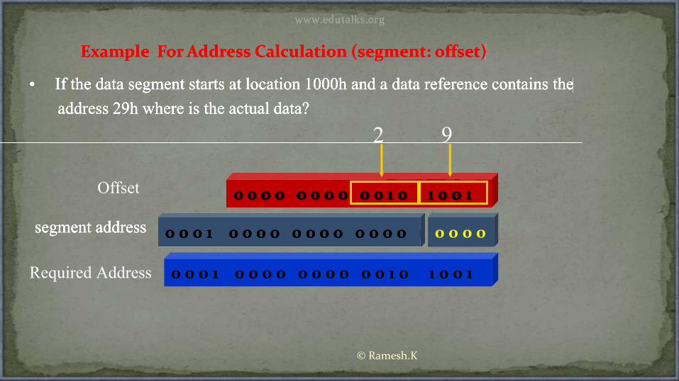
• If the data segment starts at location 1000h and a data reference contains the
Example For Address Calculation (segment: offset)
address 29h where is the actual data?
0 0 0 0 0 0 0 0 0 0 1 0 1 0 0 1
segment address 0 0 0 1 0 0 0 0 0 0 0 0 0 0 0 0
• If the data segment starts at location 1000h and a data reference contains the
Example For Address Calculation (segment: offset)
address 29h where is the actual data?
0 0 0 0 0 0 0 0 0 0 1 0 1 0 0 10 0 0 0 0 0 0 0 0 0 1 0 1 0 0 10 0 0 0 0 0 0 0 0 0 1 0 1 0 0 10 0 0 0 0 0 0 0 0 0 1 0 1 0 0 10 0 0 0 0 0 0 0 0 0 1 0 1 0 0 10 0 0 0 0 0 0 0 0 0 1 0 1 0 0 10 0 0 0 0 0 0 0 0 0 1 0 1 0 0 10 0 0 0 0 0 0 0 0 0 1 0 1 0 0 10 0 0 0 0 0 0 0 0 0 1 0 1 0 0 10 0 0 0 0 0 0 0 0 0 1 0 1 0 0 10 0 0 0 0 0 0 0 0 0 1 0 1 0 0 10 0 0 0 0 0 0 0 0 0 1 0 1 0 0 10 0 0 0 0 0 0 0 0 0 1 0 1 0 0 10 0 0 0 0 0 0 0 0 0 1 0 1 0 0 10 0 0 0 0 0 0 0 0 0 1 0 1 0 0 10 0 0 0 0 0 0 0 0 0 1 0 1 0 0 10 0 0 0 0 0 0 0 0 0 1 0 1 0 0 10 0 0 0 0 0 0 0 0 0 1 0 1 0 0 10 0 0 0 0 0 0 0 0 0 1 0 1 0 0 10 0 0 0 0 0 0 0 0 0 1 0 1 0 0 10 0 0 0 0 0 0 0 0 0 1 0 1 0 0 10 0 0 0 0 0 0 0 0 0 1 0 1 0 0 10 0 0 0 0 0 0 0 0 0 1 0 1 0 0 10 0 0 0 0 0 0 0 0 0 1 0 1 0 0 10 0 0 0 0 0 0 0 0 0 1 0 1 0 0 10 0 0 0 0 0 0 0 0 0 1 0 1 0 0 10 0 0 0 0 0 0 0 0 0 1 0 1 0 0 10 0 0 0 0 0 0 0 0 0 1 0 1 0 0 10 0 0 0 0 0 0 0 0 0 1 0 1 0 0 10 0 0 0 0 0 0 0 0 0 1 0 1 0 0 1
segment address 0 0 0 1 0 0 0 0 0 0 0 0 0 0 0 0 0 0 0 1 0 0 0 0 0 0 0 0 0 0 0 0 0 0 0 0
Offset
2 9
0 0 0 1 0 0 0 0 0 0 0 0 0 0 1 0 1 0 0 1Required Address
© Ramesh.K
www.edutalks.org

© Ramesh.K
References
Microprocessor Architecture and InterfacingHall. D. V
Advanced Microprocessors and PeripheralsA K Ray & K M Bhurchandi
The Intel MicroprocessorsBarry B. Bray
The 8086.pptMr. Suresh
(H.O.D , department of Electronics and Communication, MEA Engg College, vengoor)
Microprocessors And Microcomputer-
Based System DesignMohammed Rafiquzzaman
www.edutalks.org


![Index [dlcdnets.asus.com] Card/Manual...2.1.1 ®Installing the VGA drivers in Windows 10 / 8.1 / 8 / 7 (64-bit) To install the VGA driver in Windows® 10 / 8.1 / 8 / 7 (64-bit): 1.](https://static.fdocuments.in/doc/165x107/6094fa4b0664d554d21324da/index-cardmanual-211-installing-the-vga-drivers-in-windows-10-81.jpg)