A Practical Method of BLDCM Based on High-precision ... · PDF fileBased on High-precision...
7
A Practical Method of BLDCM Based on High-precision Estimation of the Rotor Position ZHOU Aiguo, YANG Lang, PAN Qiangbiao, and SHEN Yong Abstract—Approaches of staring sensorless BLDCM have been of the research concentrations in the last decade. This paper in the first place elaborates connections between winding inductance and rotor position as well as relationships between torque and torque angle. Based on theories above, a new method of estimating the rotor position and starting sen- sorless BLDCM is proposed. This method uses voltage pulses, which are generated in two-phase and three-phase conduction modes, to identify the rotor position within a maximum error of 7.5 in electrical degrees. In this way, starting vibration will be reduced, leading to a higher starting success rate. Expe- riments on a sample BLDCM prove the feasibility of this new method. Index Terms—BLDCM, inductance, initial position, sensor- less I. INTRODUCTION ENSORLESS Brushless Direct Current Motors (BLDCM) have been popular in various industrial ap- plications in the recent ten years, especially in pumps, for its high reliability, small size and light weight [1]-[2]. A tradi- tional way of rotor position detection based on BEMF ZCP (Back Electromotive Force zero-crossing point) has been widely applied in sensorless BLDCM. However, BEMF ZCP cannot be detected when no rotor movement causes BEMF signals [3]. Nevertheless, estimation of initial rotor position must be executed, otherwise vibration or reversal may occur during the starting period. References [4]-[6] can estimate the initial rotor position within a maximum error of 15 in electrical degrees. However in this paper, the estimation error of rotor position will be narrowed down to 7.5 in electrical degrees and a specific starting-up method follows up. Moreover, principles of estimation based on inductance variation are elaborated in details. II. ANALYSIS OF WINDING INDUCTANCE In A-B-C coordinate frame, three-phase voltages can be expressed as Manuscript is received on October 15, 2015; revised on February 5, 2016. ZHOU Aiguo is an associate professor in School of Mechanical and Energy Eng., Tongji University, China, e-mail: [email protected]. YANG Lang is a postgraduate student in School of Mechanical and Energy Eng., Tongji University, China, e-mail: [email protected]. PAN Qiangbiao is a postgraduate student in School of Mechanical and Energy Eng., Tongji University, China, e-mail: 149679087 @qq.com. SHEN Yong is a professor in School of Automotive Studies, Tongji University, China, e-mail: [email protected]. 0 0 , 0 0 , 0 0 , A T T A B C A B C B C R i uuu R iii p i R i (1) where A u , B u and C u are voltages; R is the resistance; A i , B i and C i are currents; , A i , , B i and , C i are total flux linkage of phase A, B and C respectively. p is dif- ferential operator and θ is the angle between rotor's d-axis and α-axis in α-β coordinate frame. According to (1), as long as the phase voltage remains constant, the current response is only affected by total flux linkage which contains the rotor position information. Ac- tually, total flux linkage depends on winding inductance, that is, rotor position information lies in winding inductance. Winding inductance comprises of two parts - leakage in- ductance (ignored) and main inductance. Under the effect of both magnetomotive force (MMF) and permanent magnet flux (PM flux), main inductance varies in accordance with the rotor position [4]. A. The Effect of MMF The main inductance of phase winding can be generally expressed as 2 A A m L N (2) where A N is the equivalent turns of windings and m is the permeance of the main inductance. Reluctance is the reci- procal of permeance, that is 1/ m m R . According to (2), A L is proportional to m when winding distribution pat- terns and winding turns are ascertained. Magnetic circuit in BLDCM passes through the air gap, PM and the rotor core. The total reluctance can be described as below. 0 0 0 0 m m mPM mFe Fe PM PM PM Fe Fe R R R R l l l A A A (3) where 0 l , PM l and Fe l are length of magnetic circuit path; 0 , PM and Fe are permeability; 0 A , PM A and Fe A are sectional areas of air, PM and the rotor core respectively. Fig. 1a, Fig. 1b and Fig. 1c show three kinds of equiva- lent magnetic circuits with different rotor positions. Fe is much larger than PM which nearly equals 0 , as a result, the longer PM l is, the larger m R is [3]. In the situation of Fig. 1a, stator current flows into phase A and out of phase B, creating MMF a F which is parallel to PM axis. So PM l maximizes while Fe l minimizes. Based on (3), m R max- imizes and inductance minimizes. In the situation of Fig. 1b, S Engineering Letters, 24:2, EL_24_2_04 (Advance online publication: 18 May 2016) ______________________________________________________________________________________
Transcript of A Practical Method of BLDCM Based on High-precision ... · PDF fileBased on High-precision...

A Practical Method of BLDCM
Based on High-precision Estimation of the Rotor
Position
ZHOU Aiguo, YANG Lang, PAN Qiangbiao, and SHEN Yong
Abstract—Approaches of staring sensorless BLDCM have
been of the research concentrations in the last decade. This
paper in the first place elaborates connections between
winding inductance and rotor position as well as relationships
between torque and torque angle. Based on theories above, a
new method of estimating the rotor position and starting sen-
sorless BLDCM is proposed. This method uses voltage pulses,
which are generated in two-phase and three-phase conduction
modes, to identify the rotor position within a maximum error
of 7.5 in electrical degrees. In this way, starting vibration
will be reduced, leading to a higher starting success rate. Expe-
riments on a sample BLDCM prove the feasibility of this new
method.
Index Terms—BLDCM, inductance, initial position, sensor-
less
I. INTRODUCTION
ENSORLESS Brushless Direct Current Motors
(BLDCM) have been popular in various industrial ap-
plications in the recent ten years, especially in pumps, for its
high reliability, small size and light weight [1]-[2]. A tradi-
tional way of rotor position detection based on BEMF ZCP
(Back Electromotive Force zero-crossing point) has been
widely applied in sensorless BLDCM. However, BEMF
ZCP cannot be detected when no rotor movement causes
BEMF signals [3].
Nevertheless, estimation of initial rotor position must be
executed, otherwise vibration or reversal may occur during
the starting period.
References [4]-[6] can estimate the initial rotor position
within a maximum error of 15 in electrical degrees.
However in this paper, the estimation error of rotor position
will be narrowed down to 7.5 in electrical degrees and a
specific starting-up method follows up. Moreover, principles
of estimation based on inductance variation are elaborated in
details.
II. ANALYSIS OF WINDING INDUCTANCE
In A-B-C coordinate frame, three-phase voltages can be
expressed as
Manuscript is received on October 15, 2015; revised on February 5,
2016. ZHOU Aiguo is an associate professor in School of Mechanical and
Energy Eng., Tongji University, China, e-mail: [email protected].
YANG Lang is a postgraduate student in School of Mechanical and Energy Eng., Tongji University, China, e-mail: [email protected].
PAN Qiangbiao is a postgraduate student in School of Mechanical and
Energy Eng., Tongji University, China, e-mail: 149679087 @qq.com.
SHEN Yong is a professor in School of Automotive Studies, Tongji
University, China, e-mail: [email protected].
0 0 ,
0 0 ,
0 0 ,
AT T
A B C A B C B
C
R i
u u u R i i i p i
R i
(1)
where Au , Bu and Cu are voltages; R is the resistance;
Ai , Bi and Ci are currents; ,A i , ,B i and ,C i are
total flux linkage of phase A, B and C respectively. p is dif-
ferential operator and θ is the angle between rotor's d-axis
and α-axis in α-β coordinate frame.
According to (1), as long as the phase voltage remains
constant, the current response is only affected by total flux
linkage which contains the rotor position information. Ac-
tually, total flux linkage depends on winding inductance,
that is, rotor position information lies in winding inductance.
Winding inductance comprises of two parts - leakage in-
ductance (ignored) and main inductance. Under the effect of
both magnetomotive force (MMF) and permanent magnet
flux (PM flux), main inductance varies in accordance with
the rotor position [4].
A. The Effect of MMF
The main inductance of phase winding can be generally
expressed as 2
A A mL N (2)
where AN is the equivalent turns of windings and m is the
permeance of the main inductance. Reluctance is the reci-
procal of permeance, that is 1/m mR . According to (2),
AL is proportional to m when winding distribution pat-
terns and winding turns are ascertained.
Magnetic circuit in BLDCM passes through the air gap,
PM and the rotor core. The total reluctance can be described
as below.
0
0
0 0
m m mPM mFe
FePM
PM PM Fe Fe
R R R R
l ll
A A A
(3)
where 0l , PMl and Fel are length of magnetic circuit
path; 0 , PM and Fe are permeability; 0A , PMA and FeA are
sectional areas of air, PM and the rotor core respectively.
Fig. 1a, Fig. 1b and Fig. 1c show three kinds of equiva-
lent magnetic circuits with different rotor positions. Fe is
much larger than PM which nearly equals 0 , as a result,
the longer PMl is, the larger mR is [3]. In the situation of
Fig. 1a, stator current flows into phase A and out of phase B,
creating MMF aF which is parallel to PM axis. So PMl
maximizes while Fel minimizes. Based on (3), mR max-
imizes and inductance minimizes. In the situation of Fig. 1b,
S
Engineering Letters, 24:2, EL_24_2_04
(Advance online publication: 18 May 2016)
______________________________________________________________________________________
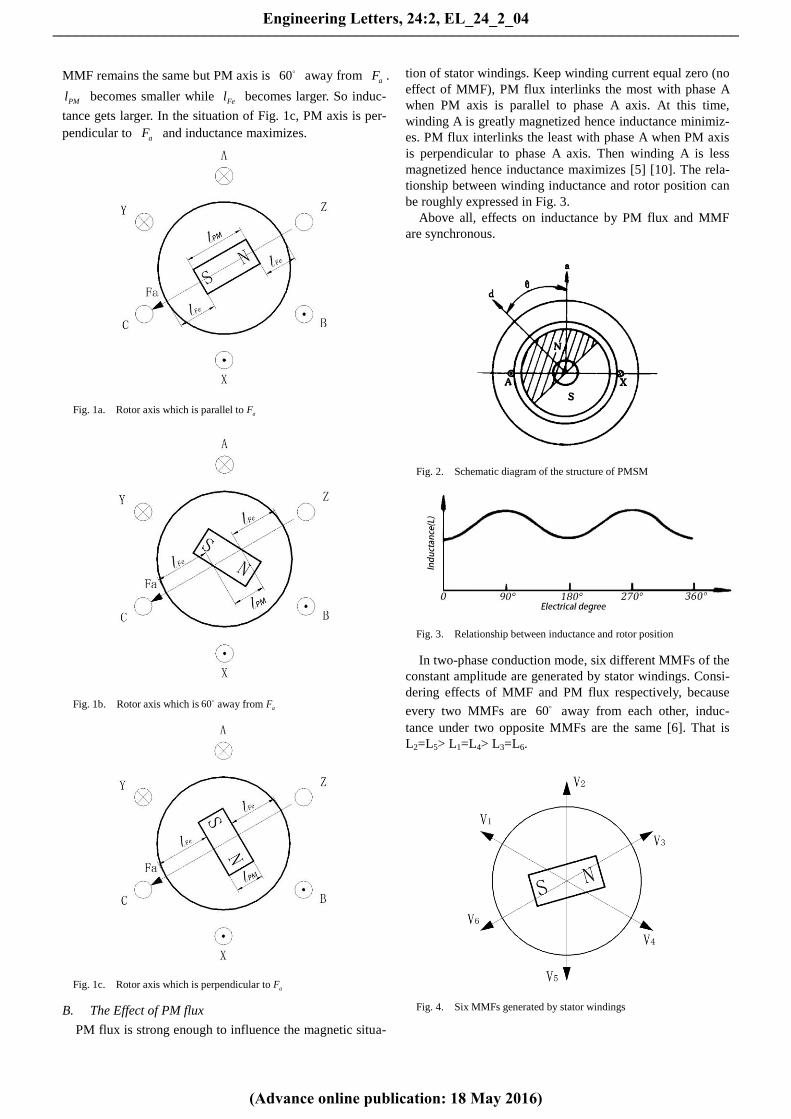
MMF remains the same but PM axis is 60 away from aF .
PMl becomes smaller while Fel becomes larger. So induc-
tance gets larger. In the situation of Fig. 1c, PM axis is per-
pendicular to aF and inductance maximizes.
Fig. 1a. Rotor axis which is parallel to aF
Fig. 1b. Rotor axis which is 60away from aF
Fig. 1c. Rotor axis which is perpendicular to aF
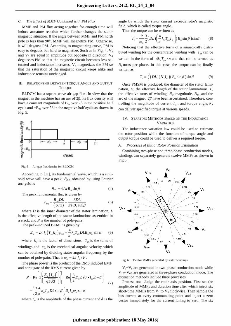
B. The Effect of PM flux
PM flux is strong enough to influence the magnetic situa-
tion of stator windings. Keep winding current equal zero (no
effect of MMF), PM flux interlinks the most with phase A
when PM axis is parallel to phase A axis. At this time,
winding A is greatly magnetized hence inductance minimiz-
es. PM flux interlinks the least with phase A when PM axis
is perpendicular to phase A axis. Then winding A is less
magnetized hence inductance maximizes [5] [10]. The rela-
tionship between winding inductance and rotor position can
be roughly expressed in Fig. 3.
Above all, effects on inductance by PM flux and MMF
are synchronous.
Fig. 2. Schematic diagram of the structure of PMSM
Fig. 3. Relationship between inductance and rotor position
In two-phase conduction mode, six different MMFs of the
constant amplitude are generated by stator windings. Consi-
dering effects of MMF and PM flux respectively, because
every two MMFs are 60 away from each other, induc-
tance under two opposite MMFs are the same [6]. That is
L2=L5> L1=L4> L3=L6.
Fig. 4. Six MMFs generated by stator windings
Engineering Letters, 24:2, EL_24_2_04
(Advance online publication: 18 May 2016)
______________________________________________________________________________________
C. The Effect of MMF Combined with PM Flux
MMF and PM flux acting together for enough time will
induce armature reaction which further changes the stator
magnetic situation. If the angle between MMF and PM north
pole is less than 90 , MMF will magnetize PM. Otherwise,
it will degauss PM. According to magnetizing curve, PM is
easy to degauss but hard to magnetize. Such as in Fig. 4, V3
and V6 are equal in amplitude but opposite in direction. V6
degausses PM so that the magnetic circuit becomes less sa-
turated and inductance increases. V3 magnetizes the PM so
that the saturation of the magnetic circuit keeps alike and
inductance remains unchanged.
III. RELATIONSHIP BETWEEN TORQUE ANGLE AND OUTPUT
TORQUE
BLDCM has a square-wave air gap flux. In view that the
magnet in the machine has an arc of 2β, its flux density will
have a constant magnitude of Bm over 2β in the positive half
cycle and −Bm over 2β in the negative half cycle as shown in
Fig. 5.
Fig. 5. Air gap flux density for BLDCM
According to [11], its fundamental wave, which is a sinu-
soid wave will have a peak, Bm1, obtained by using Fourier
analysis as
Bm1= 4 / sinmB (4)
The peak fundamental flux is given by
1
1
8
/ 2 sin
mm
m
B DL DL
p PB
(5)
where D is the inner diameter of the stator lamination, L
is the effective length of the stator laminations assembled in
a stack, and P is the number of pole-pairs.
The peak-induced BEMF is given by
1
42 sinm s ph m ph m mE f T k k T DLB
(6)
where k is the factor of dimensions, phT is the turns of
windings and m is the mechanical angular velocity which
can be obtained by dividing stator angular frequency by the
number of pole-pairs. That is 2 /m sf P .
The phase power is the product of the RMS induced EMF
and conjugate of the RMS current given by
*
3Re 3 Re 90
22 2
3 4sin sin
2
m m
m m
ph m m m
E IP E I
k T DL B I
(7)
where mI is the amplitude of the phase current and is the
angle by which the stator current exceeds rotor's magnetic
field, which is called torque angle.
Then the torque can be written as
3 4
sin sin2
e ph m m
m
PT DL k T I B
(8)
Noticing that the effective turns of a sinusoidally distri-
buted winding for the concentrated winding with phT can be
written in the form of 4 /phk T and that can be termed as
Ns turns per phase. In this case, the torque can be finally
written as
3
sin sin2
e s m mT DL N I B (9)
Once PMSM is produced, the diameter of the stator lami-
nation, D, the effective length of the stator laminations, L,
the effective turns of winding, Ns, magnitude, Bm, and the
arc of the magnet, 2β have been ascertained. Therefore, con-
trolling the magnitude of current, mI , and torque angle, ,
can deliver specified torque at various speeds.
IV. STARTING METHODS BASED ON THE INDUCTANCE
VARIATION
The inductance variation law could be used to estimate
the rotor position while the function of torque angle and
output torque could be used to deliver a required torque.
A. Processes of Initial Rotor Position Estimation
Combining two-phase and three-phase conduction modes,
windings can separately generate twelve MMFs as shown in
Fig.6.
Fig. 6. Twelve MMFs generated by stator windings
V1~V6 are generated in two-phase conduction mode while
V1.5~V6.5 are generated in three-phase conduction mode. The
estimation methods include three processes.
Process one: Judge the rotor axis position. First set the
amplitude of MMFs and duration time after which inject six
short-time MMFs from V1 to V6 clockwise. Then sample the
bus current at every commutating point and inject a zero
vector immediately for the current falling to zero. The six
Engineering Letters, 24:2, EL_24_2_04
(Advance online publication: 18 May 2016)
______________________________________________________________________________________

sampling current values present two kinds of regularity [9].
1). "Two large ones and four small ones" is presented if
rotor axis lies closed to certain estimating MMF. With ref-
erence to Fig. 6, when rotor axis lies near V2 and V5 (in
areas 2L~2R and 5L~5R), inductances under V1, V4 and V3,
V6 are relatively large hence the sampling values are rela-
tively small. Inductances under V2 and V5 are relatively
small hence the sampling values are large.
2). "Four large ones and two small ones" is presented if
the rotor axis lies in the middle of two adjacent estimating
MMFs. With reference to Fig. 6, when the rotor axis lies in
the middle of V1 and V2, V4 and V5 (in areas 1.5L~1.5R and
4.5L~4.5R), inductances under V1,V4 and V2,V5 are rela-
tively small hence the sampling values are relatively large.
Inductances under V3 and V6 are relatively large hence the
sampling values are small.
Process two: Judge PM direction. Provided that north pole
and south pole lie in areas 1.5L~1.5R and 4.5L~4.5R re-
spectively, inject estimating MMF V1.5 and V4.5 successively
for an adequate time to induce obvious armature reaction.
V1.5 magnetizes the PM so winding inductance stays alike
while V4.5 degausses PM so winding inductance drops. As a
consequence, I1.5 is larger than I4.5.
Process three: Narrow down the estimation error. Assum-
ing the north pole lies in area 1.5L~1.5R, inject V1 and V2
after which store I1 and I2. If I1 > I2, the north pole is in 1.5L
otherwise in 1.5R. Process three minishes the error to 7.5
or a maximum error of 15.
The estimation processes can be concluded as Fig. 7.
Fig. 7. The rotor position estimation flow chart
Duration of MMF in each process is worth discussing. In
process one and three, duration should be as short as possi-
ble but the difference of sampling values should be distin-
guished. Overlong duration for a short-time pulse may in-
duce armature reaction and a longer delay is additionally
needed for the current dropping to zero. MMFs in process
two last for longer to ensure armature reaction. Whereas the
rotor won't easily be driven because the torque angle is not
beyond 15 .
B. Selection of Driving MMF and PWM Duty
This paper adopts an open-loop control based on PWM.
First identify the initial rotor position and then deploy a
correlative driving MMF after setting a proper PWM duty.
Once the rotor rotates at an adequate speed where BEMF
ZCP can be detected by the detection circuit, the
BEMF-based commutation mode begins and the starting
procedure ends. This starting method is referred to the start-
ing processes of BLDCM with hall sensors which also first
creates a certain MMF and commutates when a new rotor
position signal comes. It is worth noticing that BEMF ZCP
could also be observed when estimating MMFs, V1~V6, are
being injected one by one. It is because MMFs revolve
around the rotor, in return, relatively, the rotor revolves
around the windings.
According to (4), the torque angle should be 90 as
much as possible to deliver a powerful torque. As shown in
Fig. 6, assume the rotor rotates clockwise. When the north
pole lies in area 1.5L, the driving MMF should be V3. Dur-
ing the rotor rotates from 1.5L to 1.5R, sin first increases
and then drops. However, when the north pole is in 1.5R, the
driving MMF should also be V3 but sin monotonously
decreases. On the premise that the bus current keeps con-
stant, the equivalent torque starting from 1.5L is bigger than
that starting from 1.5R. To guarantee the starting torque
steady, PWMSTART duty when the rotor is in 1.5L should be
marginally greater than that when the rotor is in 1.5R.
Moreover, a MMF produced in three-phase conduction
mode can be regarded as a composition by two MMFs pro-
duced in two-phase conduction mode. Suppose the north
pole is right at the position of V2, V3.5 is the driving MMFs.
In this situation, V3.5 could be regarded as a composition by
V3 and V4. Assuming the phase current value is phI , the
torque is given referring to (9) as follows
3.5 3 4
3 2sin sin sin
2 3 3
33 sin
2
s ph m
s ph m
T T T
DL N I B
DL N I B
(10)
However, the torque in two-phase conduction mode is
written as
3
sin2
two s ph mT DL N I B (11)
Regardless of the energy loss of the inverter, 3.5T is 3
times twoT . Therefore, PWM duty in three-phase conduction
mode, Dutythree, should be set at 1/ 3 times PWM duty in
two-phase conduction mode, Dutytwo.
PWMSTART duty configuration relies on the load, too. If
the load is steady, the optimal duty can be acquired by trial
and error. If the load is different each time the machine starts,
the PWM duty could raise gradually until succeeding in
starting. The starting flow chart is shown as Fig. 8.
Engineering Letters, 24:2, EL_24_2_04
(Advance online publication: 18 May 2016)
______________________________________________________________________________________

TABLE I
ROTOR POSITION ESTIMATION METHODS AND CORRELATIVE DRIVING MMFS
Process one Process Two Process Three Driving MMF
Current
Regu-
larity
Short-t
ime
MMFs
Sam-
pling
Values
Rotor
Axis
Position
long-t
ime
MMF
s
Sam-
pling
Values
North
Pole
Posi-
tion
Short-t
ime
MMFs
Sam-
pling
Values
North
Pole
Posi-
tion
MMF PWMSTART
Duty
"Two
large
ones and
four
small
ones"
V1~V6
Two
large
ones
I1,I4
1L, 1R
and
4L, 4R
V1,V4
I1>I4 1L,
1R
V6.5,
V1.5
I6.5>I1.5 1L V2.5 DutythreeL
I6.5<I1.5 1R V2.5 DutythreeR
I1<I4 4L,
4R
V3.5,
V4.5
I3.5>I4.5 4L V5.5 DutythreeL
I3.5<I4.5 4R V5.5 DutythreeR
Two
large
ones
I2,I5
2L, 2R
and
5L,5R
V2,V5
I2>I5 2L,
2R
V1.5,
V2.5
I1.5>I2.5 2L V3.5 DutythreeL
I1.5<I2.5 2R V3.5 DutythreeR
I2<I5 5L,
5R
V4.5,
V5.5
I4.5>I5.5 5L V6.5 DutythreeL
I4.5<I5.5 5R V6.5 DutythreeR
Two
large
ones
I3,I6
3L, 3R
and
6L, 6R
V3,V6
I3>I6 3L,
3R
V2.5,
V3.5
I2.5>I3.5 3L V4.5 DutythreeL
I2.5<I3.5 3R V4.5 DutythreeR
I3<I6 6L,
6R
V5.5,
V6.5
I5.5>I6.5 6L V1.5 DutythreeL
I5.5<I6.5 6R V1.5 DutythreeR
"Four
large
ones and
two
small
ones"
V1~V6
Two
small
ones
I1,I4
2.5L,
2.5R
and
5.5L,
5.5R
V2.5,
V5.5
I2.5>I5.5 2.5L,
2.5R V2,V3
I2>I3 2.5L V4 DutytwoL
I2<I3 2.5R V4 DutytwoR
I2.5<I5.5 5.5L,
5.5R V5,V6
I5>I6 5.5L V1 DutytwoL
I5<I6 5.5R V1 DutytwoR
Two
small
ones
I2,I5
3.5L,
3.5R
and
6.5L,
6.5R
V3.5,
V6.5
I3.5>I6.5 3.5L,
3.5R V3,V4
I3>I4 3.5L V5 DutytwoL
I3<I4 3.5R V5 DutytwoR
I3.5<I6.5 6.5L,
6.5R V6,V1
I6>I1 6.5L V2 DutytwoL
I6<I1 6.5R V2 DutytwoR
Two
small
ones
I3,I6
1.5L,
1.5R
and
4.5L,
4.5R
V1.5,
V4.5
I1.5>I4.5 1.5L,
1.5R V1,V2
I1>I2 1.5L V3 DutytwoL
I1<I2 1.5R V3 DutytwoR
I1.5<I4.5 4.5L,
4.5R V4,V5
I4>I5 4.5L V6 DutytwoL
I4<I5 4.5R V6 DutytwoR
Fig. 8. The starting flow chart
Table I concludes estimation methods of the initial rotor
position and the correlative driving MMFs. (Providing the
rotor rotates clockwise.)
V. EXPERIMENTAL RESULTS
Methods mentioned above have been verified on a
BLDC prototype (Fig. 9). BLDCM is supplied by a 15V
DC power. PWM frequency is set at 20KHz with a duty of
50% and no load. Every MMF lasts for 1ms with a 1-ms
interval and finally store the current value under every
MMF. Fig. 10 is the current waveform displayed on the
oscilloscope and Fig. 11 is the sampled current waveform
depicted by 300 sample points. Fig. 10 and Fig. 11 present
the "two large ones and four small ones" regularity. Thus
this match proves PWM frequency, duty as well as duration
is configured properly. Moreover, peak-peak differences
among sample values are huge enough to ensure the ro-
bustness. In the similar way, Fig. 12 and Fig. 13 present the
"four large ones and two small ones" regularity.
Engineering Letters, 24:2, EL_24_2_04
(Advance online publication: 18 May 2016)
______________________________________________________________________________________

Fig. 9. The experimental setup
Fig. 10. "Two large ones and four small ones" regularity
Fig. 11. Sampled "two large ones and four small ones" regularity
Fig. 12. "Four large ones and two small ones" regularity
Fig. 13. Sampled "four large ones and two small ones" regularity
In the second estimation process, each opposite MMF
lasts for 5ms with a 1-ms interval. The current value dif-
ference between the two opposite MMFs can be distin-
guished (as shown in Fig. 14).
Fig. 14. Sampled current waveform of the two opposite MMFs in es-
timation process two
Fig. 15 depicts the starting current during the first 75ms
since the machine starts. It's obvious that the machine under
sensorless mode takes a rather long time to accelerate until
the ZCP signal is caught for the purpose of stability. Before
the commutation moment, the current rises slowly in lad-
der-like shape under a lower voltage on account of the limit
of sampling precision. After catching the ZCP signal, the
current surges to its peak and the motor starts a high-speed
BEMF-based commutation mode.
However, current in hall-sensor-based mode rises sharply
from the beginning, so the machine can enter the commuta-
tion stage immediately no matter how fast the rotor rotates.
Hence, the first commutation in sensorless way comes later
than that in hall-based way. Nevertheless, at the cost of
starting torque and time, the sensorless way performs more
flexibly.
Fig. 15. Sampled current waveform of the starting period
Engineering Letters, 24:2, EL_24_2_04
(Advance online publication: 18 May 2016)
______________________________________________________________________________________
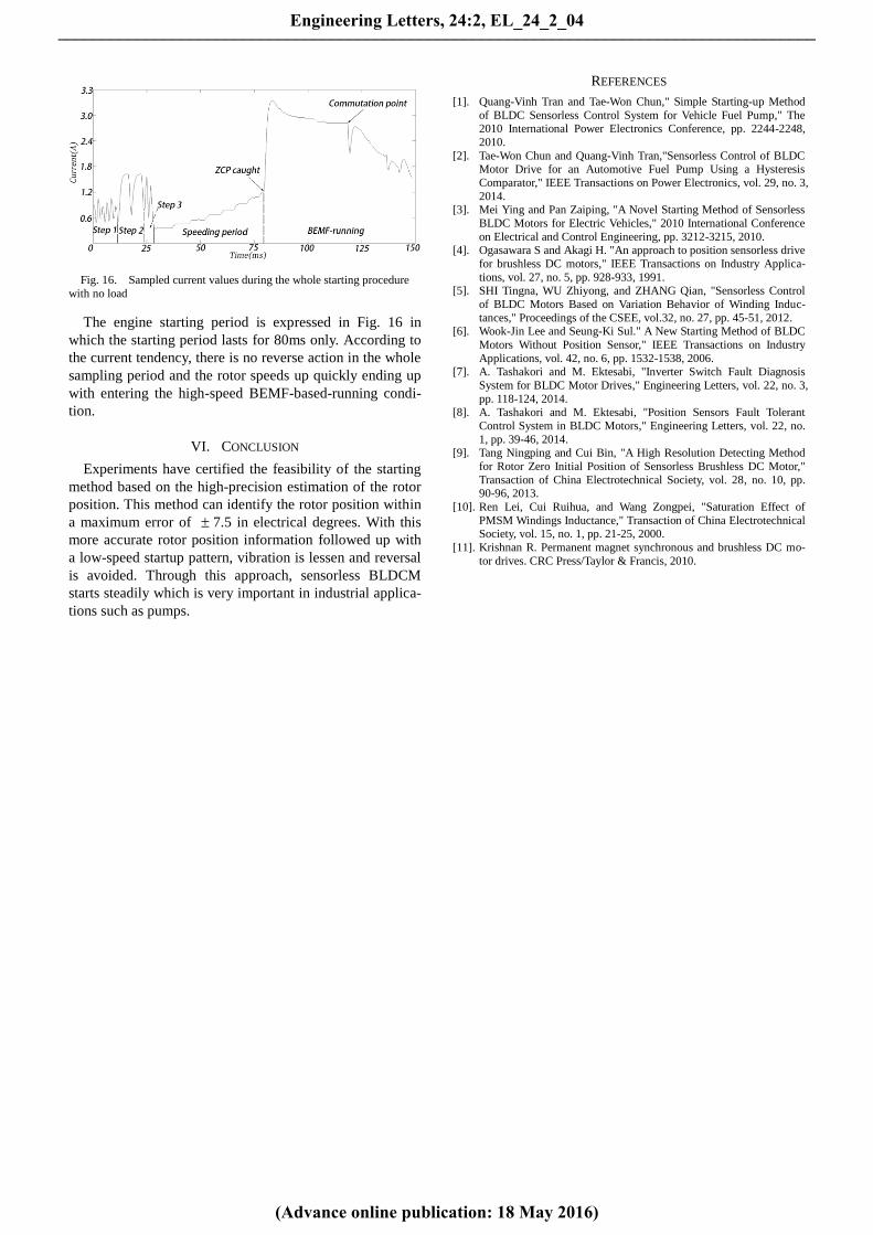
Fig. 16. Sampled current values during the whole starting procedure
with no load
The engine starting period is expressed in Fig. 16 in
which the starting period lasts for 80ms only. According to
the current tendency, there is no reverse action in the whole
sampling period and the rotor speeds up quickly ending up
with entering the high-speed BEMF-based-running condi-
tion.
VI. CONCLUSION
Experiments have certified the feasibility of the starting
method based on the high-precision estimation of the rotor
position. This method can identify the rotor position within
a maximum error of 7.5 in electrical degrees. With this
more accurate rotor position information followed up with
a low-speed startup pattern, vibration is lessen and reversal
is avoided. Through this approach, sensorless BLDCM
starts steadily which is very important in industrial applica-
tions such as pumps.
REFERENCES
[1]. Quang-Vinh Tran and Tae-Won Chun," Simple Starting-up Method
of BLDC Sensorless Control System for Vehicle Fuel Pump," The
2010 International Power Electronics Conference, pp. 2244-2248,
2010.
[2]. Tae-Won Chun and Quang-Vinh Tran,"Sensorless Control of BLDC Motor Drive for an Automotive Fuel Pump Using a Hysteresis
Comparator," IEEE Transactions on Power Electronics, vol. 29, no. 3,
2014. [3]. Mei Ying and Pan Zaiping, "A Novel Starting Method of Sensorless
BLDC Motors for Electric Vehicles," 2010 International Conference
on Electrical and Control Engineering, pp. 3212-3215, 2010. [4]. Ogasawara S and Akagi H. "An approach to position sensorless drive
for brushless DC motors," IEEE Transactions on Industry Applica-
tions, vol. 27, no. 5, pp. 928-933, 1991. [5]. SHI Tingna, WU Zhiyong, and ZHANG Qian, "Sensorless Control
of BLDC Motors Based on Variation Behavior of Winding Induc-
tances," Proceedings of the CSEE, vol.32, no. 27, pp. 45-51, 2012. [6]. Wook-Jin Lee and Seung-Ki Sul." A New Starting Method of BLDC
Motors Without Position Sensor," IEEE Transactions on Industry
Applications, vol. 42, no. 6, pp. 1532-1538, 2006.
[7]. A. Tashakori and M. Ektesabi, "Inverter Switch Fault Diagnosis
System for BLDC Motor Drives," Engineering Letters, vol. 22, no. 3,
pp. 118-124, 2014. [8]. A. Tashakori and M. Ektesabi, "Position Sensors Fault Tolerant
Control System in BLDC Motors," Engineering Letters, vol. 22, no.
1, pp. 39-46, 2014. [9]. Tang Ningping and Cui Bin, "A High Resolution Detecting Method
for Rotor Zero Initial Position of Sensorless Brushless DC Motor,"
Transaction of China Electrotechnical Society, vol. 28, no. 10, pp. 90-96, 2013.
[10]. Ren Lei, Cui Ruihua, and Wang Zongpei, "Saturation Effect of
PMSM Windings Inductance," Transaction of China Electrotechnical Society, vol. 15, no. 1, pp. 21-25, 2000.
[11]. Krishnan R. Permanent magnet synchronous and brushless DC mo-
tor drives. CRC Press/Taylor & Francis, 2010.
Engineering Letters, 24:2, EL_24_2_04
(Advance online publication: 18 May 2016)
______________________________________________________________________________________