A Practical Handbook of Preparative HPLC
193
SOFTbank E-Book Center Tehran, Phone: 66403879,66493070 For Educational Use.
Transcript of A Practical Handbook of Preparative HPLC

SOFTbank E-Book Center Tehran, Phone: 66403879,66493070 For Educational Use.

A Practical Handbook of
Preparative HPLC
1856174662_Prelims.qxd 1/19/06 9:44 AM Page i
SOFTbank E-Book Center Tehran, Phone: 66403879,66493070 For Educational Use.

Don Wellings is the Chief Scientific Officer
for Chromatide Ltd, a company specializing
in contract purification and consultancy
services. Don has been performing prepar-
ative chromatographic separations since his
PhD where he was routinely running 10 cm
diameter columns more than 20 years ago.
The wealth of knowledge accumulated over
the successive years has been as broad as it is deep.
Prior to setting up Chromatide with an ex-colleague from
Avecia, he was Technology Manager for Special Projects at
Polymer Laboratories, where he was intimately involved in the
design and development of new polymeric stationary phases
for reversed phase, normal phase, ion-exchange, affinity and
chiral HPLC. Previously Don was Technology Manager for
Separation Sciences and Solid Phase Organic Chemistry at
Avecia. During this period he developed an expertise applying
molecular modeling to the design of chiral ligands for prepar-
ative chromatography.
In the late 1990s he was involved in the installation and com-
missioning of process scale HPLC at Zeneca Pharmaceuticals.
During 18 years with CRB, ICI, Zeneca and Avecia he was
instrumental in establishing the technique of preparative
HPLC within the company and served 11 years as the secretary
of the company’s Process Scale Chromatography Group.
1856174662_Prelims.qxd 1/19/06 9:44 AM Page ii
SOFTbank E-Book Center Tehran, Phone: 66403879,66493070 For Educational Use.

A PracticalHandbook of
Preparative HPLC
Dr. Donald A. Wellings
AMSTERDAM • BOSTON • HEIDELBERG • LONDON • NEW YORK •
OXFORD • PARIS • SAN DIEGO • SINGAPORE • SYDNEY • TOKYO
1856174662_Prelims.qxd 1/19/06 9:44 AM Page iii
SOFTbank E-Book Center Tehran, Phone: 66403879,66493070 For Educational Use.

ElsevierThe Boulevard, Langford Lane, Kidlington, Oxford, OX5 1GB, UKRadarweg 29, PO Box 211, 1000 AE Amsterdam, The Netherlands
Copy © 2006 Elsevier Ltd. All rights reserved
The right of Don Wellings to be identified as the author of this work has been asserted inaccordance with the Copyright, Designs and Patents Act 1988
No part of this publication may be reproduced, stored in a retrieval system or transmitted in any form or by any means electronic, mechanical, photocopying, recording or otherwisewithout the prior written permission of the publisher
Permission may be sought directly from Elsevier’s Science & Technology Rights Department in Oxford, UK: phone: (�44) (0) 1865 843830; fax: (�44) (0) 1865 853333;email: [email protected]. Alternatively you can submit your request online by visiting the Elsevier web site at http://elsevier.com/locate/permissons, and selectingObtaining permission to use Elsevier material
NoticeNo responsibility is assumed by the publisher for any injury and/or damage to persons orproperty as a matter of products liability, negligence or otherwise, or from any use or operation of any methods, products, instructions or ideas contained in the material herein.Because of rapid advances in the medical sciences, in particular, independent verification of diagnoses and drug dosages should be made
British Library Cataloguing in Publication DataWellings, Donald A.A practical handbook of preparative HPLC1. High performance liquid chromatographyI. Title543.8�4
Library of Congress Cataloging-in-Publication DataA catalog record for this book is available from the Library of Congress
ISBN 13: 978-1-8-56-17466-4ISBN 10: 1-8-56-17466-2
Typeset by Charon Tec Ltd, Chennai, Indiawww.charontec.comPrinted and bound in Italy
06 07 08 09 10 10 9 8 7 6 5 4 3 2 1
1856174662_Prelims.qxd 1/19/06 9:44 AM Page iv
SOFTbank E-Book Center Tehran, Phone: 66403879,66493070 For Educational Use.

Contents
Preface vii
Foreword ix
Abbreviations xi
1 The history and development of preparative
HPLC 1
2 Fluid dynamics, mass transport and friction 17
3 Modes of chromatographic separation 29
Particle size 32
Pore structure, size and surface area 33
3.1 Normal phase chromatography 35
3.2 Reversed phase chromatography 37
3.3 Chiral separations 41
Chirality 42
Optical purity 43
Separation of enantiomers 44
3.4 Ion exchange chromatography 47
3.5 Exclusion chromatography 53
3.6 Affinity chromatography 54
1856174662_Prelims.qxd 1/19/06 9:44 AM Page v
SOFTbank E-Book Center Tehran, Phone: 66403879,66493070 For Educational Use.

4 How to get started 57
4.1 Packing a column 59
Column packing protocol for column type 1 63
Slurry concentration 63
Slurry and column preparation 64
Column packing protocol for column type 2 65
4.2 What and where! 66
4.3 Product recovery 69
4.4 Productivity 72
5 Process development and optimization 77
5.1 Sample self displacement for purification
of a peptide 79
Analytical HPLC 90
Gradient selection 91
Loading study 92
Flow rate optimization 93
5.2 Boxcar injections for chiral separations 95
6 Documentation and record keeping 101
6.1 Equipment qualification 103
6.2 Process documentation 105
Appendices 111
References 159
Index 167
vi Contents
1856174662_Prelims.qxd 1/19/06 9:44 AM Page vi
SOFTbank E-Book Center Tehran, Phone: 66403879,66493070 For Educational Use.

Preface
This text is intended to be a guide for both the novice to prepar-
ative HPLC, and as an aid to the chemical engineer planning to
introduce this ‘black art’ into the industrial environment.
The first question to ask is ‘What is preparative?’ To many, the
isolation of a few grams of an extremely potent molecule may be
considered as largescale. In some instances 50 g of a vaccine
will supply the annual market for a particular disease state. In
more traditional drug therapies a few tonne may be more typical.
The second question to be answered is ‘What is HPLC?’ This
abbreviation is often derived from the term ‘High Performance
Liquid Chromatography’, though the term ‘High Pressure Liquid
Chromatography’ is often preferred since high performance can
also be achieved at low pressure. Just to confuse the issue, is this
the pressure created by the resistance to liquid flow through the
column or, the pressure at which the column is packed?
To help you to decide whether you have picked up the correct
book let’s be practical. This book will describe particles packed
into columns. These stationary phases are rigid porous media
1856174662_Prelims.qxd 1/19/06 9:44 AM Page vii
SOFTbank E-Book Center Tehran, Phone: 66403879,66493070 For Educational Use.

viii Preface
typically in the range of 5–30 �m in size and the columns you are
interested in are predominantly pre-packed at 2000–6000 psi or
you are going to self-pack your own dynamic axial compression
columns at 50–100 bar.
Too many chromatographic texts dwell heavily on a theoretical
and mathematical complexity that bears little relevance to what
you actually need to do in order to practice preparative HPLC.
Hopefully this book will describe how to practically go about a
preparative separation. It is designed to guide the reader through
the choice of equipment and chromatographic modes with mini-
mal fuss and with reference to only relevant formulae. Much of
the ‘black art’ will be removed by the hints and tips of a prac-
titioner with over 20 year’s experience in many modes of chro-
matographic separation.
Finally, if you know what dynamic axial compression (DAC) is
then you have the correct book so read on.
1856174662_Prelims.qxd 1/19/06 9:44 AM Page viii
SOFTbank E-Book Center Tehran, Phone: 66403879,66493070 For Educational Use.

Foreword
Don Wellings asked me to write a foreword to his book and I
am honoured and glad to do so. I have known Don for more
than fifteen years and I place him among the top prep chro-
matographers in the world today, alongside people like Gregor
Mann and Jules Dingenen.
Having been involved from the start in the creation and the
establishment of the Kromasil silica-based media business,
during many years as General Manager, I have experienced the
impressive development of preparative HPLC over the last
twenty years. The technique is now as important to learn as
other standard operations, such as distillation and crystalliza-
tion. It is often the only way of achieving sufficiently high
purity of biotech products.
Preparative HPLC plays a large role in the education programs
for chemical engineers and will do so even more in the future.
I have to admit that I myself have not read any book about
preparative HPLC except this one – the reason being that when
I graduated in 1965 there were few, if any, books available on
the subject. I am convinced, however, that this book is an ideal
1856174662_Prelims.qxd 1/19/06 9:44 AM Page ix
SOFTbank E-Book Center Tehran, Phone: 66403879,66493070 For Educational Use.

one for use at the universities, or for anybody interested in
Preparative HPLC.
For regulatory people not directly involved in the technical
process, this book gives a very good guidance in how to deal
with validation issues like GMP. If you know little about DAC,
and if you are not experienced in optimizing HPLC processes
by utilizing positive self displacement and avoiding tag along,
this book will be of high value.
The book is very nicely written and can very well defend its
place among any other book you may read, whether in a labo-
ratory setting, or even during your vacation perhaps in a sail-
ing boat moored in a quiet natural harbour, or in a comfortable
chair under a shady tree in an English garden.
Hans Liliedahl
Founder
Triple Moose Technologies
Västra gatan 51B
SE-44231 Kungälv
x Foreword
1856174662_Prelims.qxd 1/19/06 9:44 AM Page x
SOFTbank E-Book Center Tehran, Phone: 66403879,66493070 For Educational Use.

Abbreviations
APIs active pharmaceutical ingredients
cGMP current good manufacturing practice
DAC dynamic axial compression
DQ design qualification
de diastereoisomeric excess
ee enantiomeric excess
FATs factory acceptance tests
FDA Federal Drug Agency
FTEs full-time equivalents
HETP height equivalent to a theoretical plate
HPLC high performance liquid chromatography
IQ installation qualification
IUPAC International Union for Pure and Applied
Chemists
MSDSs material safety data sheets
OQ operational qualification
PQ performance qualification
PIs process instructions
PRs process records
1856174662_Prelims.qxd 1/19/06 9:44 AM Page xi
SOFTbank E-Book Center Tehran, Phone: 66403879,66493070 For Educational Use.

SATs site acceptance tests
SEM scanning electron micrograph
SMB simulated moving bed
SOPs standard operating procedures
URS user requirement specification
xii Abbreviations
1856174662_Prelims.qxd 1/19/06 9:44 AM Page xii
SOFTbank E-Book Center Tehran, Phone: 66403879,66493070 For Educational Use.

1The history and
development of preparative
HPLC
1856174662_ch01.qxd 1/18/06 1:52 PM Page 1
SOFTbank E-Book Center Tehran, Phone: 66403879,66493070 For Educational Use.

This page intentionally left blank
SOFTbank E-Book Center Tehran, Phone: 66403879,66493070 For Educational Use.

Chromatography can be defined as the separation of mixtures
by distribution between two or more immiscible phases. Some of
these immiscible phases can be gas–liquid, gas–solid, liquid–
liquid, liquid–solid, gas–liquid–solid and liquid–liquid–solid.
Strictly speaking, a simple liquid–liquid extraction is in fact a
chromatographic process. Similarly, distillation is a chromato-
graphic process that involves separation of liquids by condensa-
tion of their respective vapours at different points in a column.
Most will remember the school science project of placing an ink
blot in the centre of a filter paper and following this by dripping
methylated spirits on to the ink. Watching in fascination as con-
centric circles of various pigments develop is probably the first
and sometimes last experience of a chromatographic separa-
tion many will encounter. Like too many of our observations
the essence of this experiment is to demonstrate that black ink is
made up of several different pigments and the underlying
process, in this case chromatography, is dismissed with blatant
disregard.
Chapter One
A Colourful origin!
Chromatography was originally developed to
isolate coloured pigments from plants. Hence,
from Greek origins we get chromato, ‘colour’
and graph, ‘to record’.
1856174662_ch01.qxd 1/18/06 1:52 PM Page 3
SOFTbank E-Book Center Tehran, Phone: 66403879,66493070 For Educational Use.

4 The History and Development of Preparative HPLC
Fortunately for us, some very clever scientists have seen the
‘wood for the trees’ and have taken these simple observations
and developed them into complex, highly efficient, methods of
purification.
The invention of chromatography was rightly accredited to
Mikhail Tswett in 1902[1.1] for his detailed study of the select-
ive adsorption of leaf pigments on various adsorbents, though
somewhat unwittingly, the first demonstrations of preparative
chromatography probably stem back to ‘bleaching’ of paraffin
by passage through a carbon bed in the 1860s.
The first column based separations performed in a true indus-
trial setting can be better demonstrated by the purification of
petroleum on Fuller’s earth in the 1920s. The 1950s marked the
development of simulated moving bed (SMB) chromatography
for the separation of sucrose and fructose in the sugar industry.
However, these separations are limited low to medium pressure
The saviour of many a frustrated chemist!
Mikhail Tswett was neither chemist or chemical
engineer. In fact, he was a botanist researching
in the isolation of plant pigments.
1856174662_ch01.qxd 1/18/06 1:52 PM Page 4
SOFTbank E-Book Center Tehran, Phone: 66403879,66493070 For Educational Use.

The History and Development of Preparative HPLC 5
chromatography since the columns could be packed and oper-
ated in place. The high pressure generated by the small par-
ticles used as stationary phases in HPLC dictates the use of
specialist hardware. The columns are generally machined from
a solid ingot in order to avoid the flaws that can be observed in
welded columns. The weight of the thick walled columns nor-
mally limits the scale at which columns can be manually han-
dled so it is unusual to find pre-packed columns with a greater
than 10 cm diameter. Scaling beyond this requires fixed hard-
ware and it can be said that the first true high pressure based
preparative chromatographic separation did not arrive until the
1980s following the invention of dynamic axial compression
(DAC) based columns.
DAC, invented by Couillard[1.2] led to a dramatic change in phil-
osophy. The column packing operation could now be developed
and carried out at the point of application. Subsequently, the
scale of preparative separations would now only be limited by
the column design. The DAC concept involves the constant
compression of the packed column bed during a separation,
allowing for the concomitant removal of column dead space
formed as the bed height reduces during operation. The reduc-
tion of the bed height under flow is usually attributed to a more
regular rearrangement of the stationary phase particles within
the column or due to degradation and dissolution of the sta-
tionary phase itself.
1856174662_ch01.qxd 1/18/06 1:52 PM Page 5
SOFTbank E-Book Center Tehran, Phone: 66403879,66493070 For Educational Use.

6 The History and Development of Preparative HPLC
Probably the most important issue that had to be overcome as
the scale of operation increased was the engineering of even
flow and sample distribution over larger column diameters.
There are many ways of distributing the sample at the inlet,
and similarly collecting the eluate but the basic principle is to
deliver solvent to all points across the column diameter simul-
taneously. The flow through a column end fitting is shown
schematically in Figure 1.1, where the left hand diagram
demonstrates poor distribution resulting in a convex solvent
front, shown in red, and the right hand side shows the optimum
sample delivery.
Various distribution plates have been designed using anything
from simple engineering logic[1.3,1.4,1.5] to computational fluid
dynamics (CFD)[1.6]. Layouts vary from complex multi-
layered plates[1.7] to single discs, but the most common approach
direction ofsolvent flow
Figure 1.1
1856174662_ch01.qxd 1/18/06 1:52 PM Page 6
SOFTbank E-Book Center Tehran, Phone: 66403879,66493070 For Educational Use.

The History and Development of Preparative HPLC 7
is to use a star type distribution plate represented in schematic
form in Figure 1.2 and shown photographically in Figure 1.3.
The strategically placed and sized holes and channels allow for
a near simultaneous release of eluate over the surface area of
the column. The sinter plate, in contact with the distribution
plate on one side and stationary phase on the other, improves
the dispersion further.
Sinter plate
Channels cut indistribution plate
Distributionplate
Figure 1.2 Schematic of a typical distribution plate
1856174662_ch01.qxd 1/18/06 1:52 PM Page 7
SOFTbank E-Book Center Tehran, Phone: 66403879,66493070 For Educational Use.

8 The History and Development of Preparative HPLC
Figure 1.3 Courtesy of Jerome Theobald, NovaSep SAS
The increase in scale of preparative HPLC, brought about pre-
dominantly by the invention of DAC, resulted in a proportion-
ate demand for high quality stationary phases. A move from
the rather crude irregular silica based media used for normal
1856174662_ch01.qxd 1/18/06 1:52 PM Page 8
SOFTbank E-Book Center Tehran, Phone: 66403879,66493070 For Educational Use.

The History and Development of Preparative HPLC 9
phase chromatography towards spherical particles was now
inevitable. Figure 1.4 shows the dramatic changes that have
taken place in moving from the irregular particles of yesteryear
to the highly developed spherical particles now available. The
DAC of irregular materials leads to a mechanical degradation
resulting in the generation of fines, which ultimately results in
product contamination and blockage of the column frits. A
search for the optimum spherical silica based stationary phase
with the enhanced mechanical stability required for process
scale DAC has fuelled a whole new market for the media.
Even though DAC soon became established as the method of
choice, it took a further fifteen years before stationary phases
with uniform particle size and pore size, with the prerequisite
mechanical stability, started to appear.
Figure 1.4 Courtesy of Per Jageland, Eka Chemicals and
Gregor Mann, Schering AG
1856174662_ch01.qxd 1/18/06 1:52 PM Page 9
SOFTbank E-Book Center Tehran, Phone: 66403879,66493070 For Educational Use.

10 The History and Development of Preparative HPLC
The various modes of operation, including normal phase,
reversed phase ion exchange and chiral chromatography, will
be discussed later. However, whatever the mode of separation,
it is essential to have an understanding of the precise source of
the media. Nowadays, though a number of suppliers can
deliver high quality silica it is important to note that the sup-
plier is not always the manufacturer. Some suppliers subcon-
tract the core silica manufacture and will carry out surface
modifications in-house to provide a range of normal phase,
reversed phase and chiral stationary phases. This must be con-
sidered when working to current Good Manufacturing Practice
(cGMP) and should be included as part of the vendor qualifi-
cation process if a long-term, robust supply chain is required.
The number of suppliers that manufacture and modify station-
ary phases can be counted on one hand and the silica based
market is currently dominated by one major supplier.
The growing popularity of reversed phase chromatography
in particular has prompted polymer manufacturers to investi-
gate the use of polymeric media for this mode of operation.
Macroporous copolymers of styrene and divinylbenzene have
similar properties to silica based stationary phases bonded
with alkyl chains. However, the absence of leachables and
stability at high pH can offer advantages under certain circum-
stances. High quality, mechanically stable macroporous poly-
merics are now manufactured at much larger scales than the
1856174662_ch01.qxd 1/18/06 1:52 PM Page 10
SOFTbank E-Book Center Tehran, Phone: 66403879,66493070 For Educational Use.

equivalent silica based reversed phase media, and are particu-
larly popular in situations where the stationary phase requires
cleaning in place. The polystyrene based media are stable to
sanitization by treatment with concentrated sodium hydroxide
solution, or with steam.
The invention of novel column hardware and complex station-
ary phases would be fruitless without the hard labours of dedi-
cated chromatographers in the development of their art. The
likes of Gregor Mann[1.8], Henri Colin[1.9], Geoff Cox[1.9,1.10]
and Roger Nicoud[1.11] have been relentless in the arena of
process modelling and optimization for preparative separations,
to name a but few.
The recent surge in the popularity of preparative HPLC is prob-
ably a result of a more general urgency in the chemical indus-
try. In pharmaceutical, biotechnology and agrochemical
companies there is a market-driven force to bring products
through faster that has allowed preparative HPLC to find its
own niche. It is true that the final purification step for many
drugs in the pharmaceutical and biotechnology industry already
involves chromatography. However, in all of these industries
there are many failures along the development pipeline and the
number of man-hours, or to use a more modern term, full-time
equivalents (FTEs) wasted chasing lost leads is costly.
Preparative HPLC provides a tool to generate more compounds,
The History and Development of Preparative HPLC 11
1856174662_ch01.qxd 1/18/06 1:52 PM Page 11
SOFTbank E-Book Center Tehran, Phone: 66403879,66493070 For Educational Use.

12 The History and Development of Preparative HPLC
faster, from less pure products. It has been particularly valu-
able for chiral molecules where it can be difficult and time
consuming to develop an asymmetric synthesis in comparison
to a relatively simple separation by chiral HPLC. This mode of
separation in particular has spawned the rapid development of
SMB chromatography.
SMB is especially suited to the separation of binary mixtures,
effectively splitting a chromatogram into two halves. The dif-
ficult step now is how to describe SMB in simplistic terms.
Figure 1.5 helps to visualize the passage of a mixture of two
components down a chromatography column. It would be con-
venient at position 2 to be able to remove each component sep-
arately whilst adding a constant feed to the top of the column.
Flow
1 2 3
Figure 1.5
1856174662_ch01.qxd 1/18/06 1:52 PM Page 12
SOFTbank E-Book Center Tehran, Phone: 66403879,66493070 For Educational Use.

The History and Development of Preparative HPLC 13
The optimum process for this binary separation would be to
have fixed positions for the introduction of mobile phase and
feed, and fixed collection points for the two components of the
mixture whilst having the ability to move the stationary phase
upwards. In practice it is impossible to engineer a system
where the column bed moves, but it is possible to simulate the
movement. Such a system is shown schematically in Figure 1.6
where four columns are set in sequence with four multi-port
valves between the columns.
By the selective and carefully timed switching of the valves in
a clockwise direction, the positions of feed, eluent, extract and
Effectiverotation ofcolumn
Feed
ExtractMobile phase
Direction ofvalve rotation
Raffinate
Figure 1.6
1856174662_ch01.qxd 1/18/06 1:52 PM Page 13
SOFTbank E-Book Center Tehran, Phone: 66403879,66493070 For Educational Use.

14 The History and Development of Preparative HPLC
raffinate can be varied to allow the operator to simulate a bed
moving anticlockwise – hence SMB.
The general technique is well-established and has been used
for many years in the petrochemical[1.12] and sugar industries[1.13]
in low pressure systems. The combination of SMB with pre-
parative HPLC now allows the separation of mixtures with
close running components[1.14]. The largest high pressure SMB
system currently in operation, based at Lundbeck Pharmaceut-
icals in the UK, employs six HPLC columns of 80 cm diameter
for the chiral purification Escitalopram.
Although SMB has been used predominantly for the separ-
ation of binary mixtures over recent years, it has also proved to
be useful in the field of biotechnology[1.15]. One excellent
Confused?
Imagine two people stepping onto a travelator
at the same time. One person runs and the
other walks. Before reaching the end the two
people leave the travelator, at the same time.
Lo and behold, they are now a long way apart!
1856174662_ch01.qxd 1/18/06 1:52 PM Page 14
SOFTbank E-Book Center Tehran, Phone: 66403879,66493070 For Educational Use.

example describes the purification of antibodies[1.16] and, more
recently, the separation of nucleosides[1.17] has been discussed.
The growing market for biopharmaceuticals will undoubtedly
fuel a number of major developments in continuous chro-
matography in the years to come.
The History and Development of Preparative HPLC 15
1856174662_ch01.qxd 1/18/06 1:52 PM Page 15
SOFTbank E-Book Center Tehran, Phone: 66403879,66493070 For Educational Use.

This page intentionally left blank
SOFTbank E-Book Center Tehran, Phone: 66403879,66493070 For Educational Use.

2Fluid dynamics,mass transport
and friction
1856174662_ch02.qxd 1/18/06 8:40 AM Page 17
SOFTbank E-Book Center Tehran, Phone: 66403879,66493070 For Educational Use.

This page intentionally left blank
SOFTbank E-Book Center Tehran, Phone: 66403879,66493070 For Educational Use.
In this chapter the mass and fluid transfer processes that dom-
inate as a solvent passes over particles in a packed column bed
are summarized in both physical and philosophical terms. To
introduce some basic terminology and to put us on common
ground, the liquid passing through column is referred to as the
mobile phase whilst, in most cases, the solid particle is called
the stationary phase.
Chapter Two
Food for thought!
It will become apparent as an understanding
of the philosophy is developed that in one
particular mode of chromatography the
stationary phase is not the solid particle.
Complex mathematical formulae will be minimized here for
the purpose of simplicity since there are numerous texts that
deal with detailed theory of mass transport in chromatog-
raphy[2.1,2.2]. The flow of mobile phase through a packed col-
umn bed is shown schematically in Figure 2.1. There are two
transport mechanisms in progress. Firstly, the convectional
flow around the particles; and secondly, the diffusion in and
out of the pores of the stationary phase.
In order to describe mass transport effects it is necessary to
have an understanding of the measurements used to quantify
1856174662_ch02.qxd 1/18/06 8:40 AM Page 19
SOFTbank E-Book Center Tehran, Phone: 66403879,66493070 For Educational Use.

the efficiency of a chromatographic separation. Traditionally
the term ‘number of theoretical plates’ is used to define the
efficiency of the packed column bed. The mathematical der-
ivations for plate theory were initially developed by Martin
and Synge[2.3] and published in 1941.
20 Fluid Dynamics, Mass Transport and Friction
Solidphase (blue)
Pores(brown)
Figure 2.1
Why plates?
This term actually originated in the petro-
chemicals industry and is derived from the oil
refinery process, where an increased number
of plates in a distillation column results in a
more efficient separation.
1856174662_ch02.qxd 1/18/06 8:40 AM Page 20
SOFTbank E-Book Center Tehran, Phone: 66403879,66493070 For Educational Use.

Figure 2.2 shows the measurements to be taken from a typical
chromatogram containing two components.
As long as units are consistent throughout, the measurements
can be recorded as time or volume. The measurement V0 is the
time taken for a non-retained component to travel from the injec-
tion port to the detector. The elution positions of the retained
components, V1 and V2, respectively and the width of the first
peak at half height, W1/2 are used to calculate the number of
theoretical plates, N and the separation factor, �.
N 5.54V
W1
1/2
2
�⎛
⎝⎜⎜⎜⎜
⎞
⎠⎟⎟⎟⎟⎟
Fluid Dynamics, Mass Transport and Friction 21
Co
nc’
n
dc
ba
W1
Elution
V0
V1
V2
Figure 2.2
1856174662_ch02.qxd 1/18/06 8:40 AM Page 21
SOFTbank E-Book Center Tehran, Phone: 66403879,66493070 For Educational Use.

The separation factor �, is effectively a measure of the degree
of separation of two components. This term is derived from
the capacity factor, k�, of the corresponding peaks and is sim-
plified to produce the following equation.
The measurements a, b, c and d on the chromatogram can be
used to calculate peak asymmetry, A and resolution, R.
Another term commonly employed is the height equivalent to
a theoretical plate, HETP, which is simply the length of the col-
umn divided by the number of theoretical plates, N.
The path of a molecule dissolved in the solvent passing through
a packed bed is fraught with obstacles. This individual entity
will have to traverse the tortuous path around the stationary
phase, where the number of potential routes is numerous and at
some point during that journey it may have to seek out the
most inaccessible site at the centre of that particle.
R2(V V )
(c d)2 1�
�
�
Aba
�
� �V
V2
1
22 Fluid Dynamics, Mass Transport and Friction
1856174662_ch02.qxd 1/18/06 8:40 AM Page 22
SOFTbank E-Book Center Tehran, Phone: 66403879,66493070 For Educational Use.

Fluid Dynamics, Mass Transport and Friction 23
Picture this?
This can be likened to a mere mortal travelling
through a dense forest with the task of having
to climb the highest of trees. Imagine filling the
forest with an entire army that have all been
instilled with the same mission, add an enemy
battalion or two then flood the forest with a fast
flowing river!
In the presence of similar molecules and impurities, that mol-
ecule will also have to compete for the interactive sites on the
surface of the stationary phase. The first scientist to assess the
composite effects of mass transport in a chromatographic
column from a chemical engineering perspective was JJ van
Deemter[2.4] in the early 1950s. In doing so he derived a more
dynamic equation for the HETP which, in simplified form, can
be represented as:
where � is the mobile phase velocity and A, B and C are the
influences controlling band broadening.
HETP AB
C� ��
� �
1856174662_ch02.qxd 1/18/06 8:40 AM Page 23
SOFTbank E-Book Center Tehran, Phone: 66403879,66493070 For Educational Use.

24 Fluid Dynamics, Mass Transport and Friction
Did you know?
van Deemter was actually a physicist who
applied a knowledge of packed beds in
chemical processes to derive his classic
equation. He received a memorial medal in
1978 honouring the 75th anniversary of the
discovery of chromatography.
Component A of the equation encompasses the differing
lengths of the tortuous paths taken by the solute molecules that
ultimately leads to brand broadening. Band broadening caused
by longitudinal diffusion is accounted for by component B,
which in simple terms suggests that the less time a molecule
spends in the column, the better. However, this component is
counteracted by the resistance to mass transfer brought about
by slow diffusion within the stationary phase and by the phys-
ical interaction with the surface of the media. As a conse-
quence, high flow rates will also lead to band broadening and
the resultant third component of the equation, C, is probably
the most influential in flow rate optimization.
The optimization of flow rate is best represented graphically.
Thus a plot of HETP versus flow rate will generate a graph
similar to that shown in Figure 2.3.
1856174662_ch02.qxd 1/18/06 8:40 AM Page 24
SOFTbank E-Book Center Tehran, Phone: 66403879,66493070 For Educational Use.

For purpose of illustration, the green line represents the results
of a typical van Deemter plot. In Zone 1 the low flow rate
allows extensive longitudinal diffusion, which ultimately will
result in diffusion against the direction of flow. At high flow
rates shown in Zone 2, the decreased efficiency is a result of
comparatively slow mass transfer.
The blue line represents a situation where mass transport is rela-
tively efficient. This might be observed when particle size is
small, pore structure is large and the molecular dimensions of
the analyte are small. In an analytical sense this looks good, but
don’t be fooled. Large pore size leads to low surface area, which
consequently leads to comparatively lower loading capacity. For
an efficient preparative separation where the objective is to
maximize loading and minimize HETP it is always worth con-
sidering an investigation of pore size dimensions.
Fluid Dynamics, Mass Transport and Friction 25
Zone 2 Zone 1H
ET
P
Flow rate
Figure 2.3
1856174662_ch02.qxd 1/18/06 8:40 AM Page 25
SOFTbank E-Book Center Tehran, Phone: 66403879,66493070 For Educational Use.

26 Fluid Dynamics, Mass Transport and Friction
Think of the bigger picture!
Human Insulin contains 54 amino acids and has
a relative molecular mass of 5808. This small
globular protein will purify quite efficiently on
stationary phases with 100 Å mean pore size.
Salmon Calcitonin has 32 amino acids and a
relative molecular mass of 3432. This com-
paratively large peptide is in fact bigger than
Insulin! Try �200 Å pore size – you might be
surprised.
So! Get the stationary phase particle size as small as possible,
get the pore size optimized and you’re sailing. Slow down – it’s
not quite so simple. There are other major effects that have to
be considered when scaling a preparative separation. The fric-
tion caused by the eluent passing over stationary phase par-
ticles generates heat, which in turn reduces the viscosity of the
solvent. Cooling by conduction in the vicinity of the column
walls reduces the viscosity of the solvent close to the wall in
comparison to that at the centre of the column. Consequently,
the solvent at the centre of the column is now travelling at a
1856174662_ch02.qxd 1/18/06 8:40 AM Page 26
SOFTbank E-Book Center Tehran, Phone: 66403879,66493070 For Educational Use.

higher flow rate than that at the column walls, resulting in a
parabolic flow profile, and subsequently, to band broadening.
In practice this column wall effect is particularly dominant in
column diameters of 5 to 20 cm. This is explained schematically
in Figure 2.4, where the dashed line represents the flow pro-
file, or solvent front of the eluent and the grey area represents
the depth of cooling by conduction. Cooling by conduction
will penetrate radially to approximately the same depth with
some variation due to the thickness of the column walls. For
small diameter columns the effect is not observed since the
whole diameter is cooled by conduction. As the column diam-
eter increases the effect worsens. However, as the diameter
gets much larger the effective depth of the cooling gets smaller
in proportion to the diameter, so the effect on band broadening
is lessened.
Fluid Dynamics, Mass Transport and Friction 27
Increasing columndiameter
Figure 2.4
1856174662_ch02.qxd 1/18/06 8:40 AM Page 27
SOFTbank E-Book Center Tehran, Phone: 66403879,66493070 For Educational Use.

The effect can be counteracted by heating the column walls
and nowadays it is commonplace to use jacketed columns. If a
jacketed column is not available, the effect can be minimized
by either lagging the column or by winding a tube around the
column and circulating a heating fluid in the direction of the
outlet to the inlet of the column.
28 Fluid Dynamics, Mass Transport and Friction
1856174662_ch02.qxd 1/18/06 8:40 AM Page 28
SOFTbank E-Book Center Tehran, Phone: 66403879,66493070 For Educational Use.
3Modes of
chromatographicseparation
1856174662_ch03.qxd 1/18/06 1:53 PM Page 29
SOFTbank E-Book Center Tehran, Phone: 66403879,66493070 For Educational Use.

This page intentionally left blank
SOFTbank E-Book Center Tehran, Phone: 66403879,66493070 For Educational Use.

The most commonly utilized modes of chromatography
employed preparatively at high pressure will be summarized
in this chapter. The mode of chromatography is defined by
the mechanism of interaction between the analyte and the
stationary phase. Over one hundred years ago Mikhail Tswett[3.1]
discovered that differing solvents selectively desorbed pig-
ments from the leaves of plants. Contrary to the common belief
that different pigments were soluble in different solvents, he
correctly deduced that the selective desorption was due to vari-
ation in the interaction of the carotenoids with the cellulose
based substrate of the leaves. To demonstrate his theory, Tswett
logically chose filter paper as his stationary phase and this
hydrophilic interaction between analyte and stationary phase is
what we now refer to as ‘Normal Phase Chromatography’.
Before proceeding with a discussion on the individual modes
of separation it is worth reviewing a brief glossary of terms
in association with the stationary phase properties. A simple
strategy for selection of the stationary phase will naturally follow,
in order to help the reader to choose a supplier wisely.
There are two main classes of polymeric support utilized in the
preparation of stationary phases for all modes of chromatog-
raphy, namely silica and polystyrene-divinylbenzene copolymer.
For simplicity, from this point on, the former will be referred
to as silica and the latter class as polymeric.
Chapter Three
1856174662_ch03.qxd 1/18/06 1:53 PM Page 31
SOFTbank E-Book Center Tehran, Phone: 66403879,66493070 For Educational Use.

32 Modes of Chromatographic Separation
Particle size
The smaller the particle size the more efficient a separation
will be. However, the smaller the particle the higher the back
pressure in the packed column, which limits the practical size
that can be used due to pressure limitations of the hardware.
Typically, most equipment will be capable of withstanding the
back pressures generated by 5 �m particles at optimized flow
rates.
In theory, the more uniform spherical particle will form a bet-
ter packed bed due to the additional ease of hexagonal close
packing. In practice, the bed does pack better but there are
more important underlying factors that control the efficiency
of a separation including the surface morphology, pore struc-
ture and the pore size distribution. When considering spherical
silica based particles there are few manufacturers that come
close to supplying monodispersed stationary phases. In general
the materials are prepared with a broad particle size distribu-
tion and subsequently classified to coincide with the manufac-
turer’s specification. Conversely, polymeric stationary phases
can be prepared in monodispersed form and this is one reason
polymerics are theoretically cheaper when manufactured at
large scale, though this may not always be reflected in the
price.
1856174662_ch03.qxd 1/18/06 1:53 PM Page 32
SOFTbank E-Book Center Tehran, Phone: 66403879,66493070 For Educational Use.

Modes of Chromatographic Separation 33
Pore structure, size and surface area
The pore structure and size is critical for efficient chromatog-
raphy and this is borne out by the fact that many supports of
identical particle size, and nominally of similar pore size, often
display different characteristics. As discussed in Chapter 2,
van Deemter’s theory suggests that the most critical attribute
of a stationary phase is the ease of mass transfer through the
pores of the particle.
The control of pore size and structure during preparation is a
complex process that has been mastered by few manufacturers,
but it is true to say that pore size distribution and uniformity is
more readily achieved in silica particles than it is in polymerics.
This is not to say that polymerics are inferior, because in con-
trast these stationary phases have a more uniform particle size.
In practice, the less efficient mass transfer within polymeric
stationary phases results in a lower optimum flow rate being
obtained following a van Deemter plot. It is essential that the
Remember the forest?
The branches of an Oak are more diverse than
those of a Spruce!
1856174662_ch03.qxd 1/18/06 1:53 PM Page 33
SOFTbank E-Book Center Tehran, Phone: 66403879,66493070 For Educational Use.

34 Modes of Chromatographic Separation
data required for a van Deemter plot is collected under DAC
conditions similar to those anticipated for preparative oper-
ation. This is because the difference between silica and poly-
meric stationary phases is less pronounced when comparing
pre-packed columns. The pre-packed hardware is packed at
much higher pressures than DAC columns, which results in
deformation of the polymeric particles. This deformation of the
polymeric stationary phase reduces the interstitial spaces, giv-
ing the effect of having smaller particles.
When choosing a stationary phase, whether silica or polymer
based, it is important firstly to choose the correct pore size to
suit the analyte under investigation. Once the pore size is chosen
it will soon become apparent that a range of stationary phases
with varying surface areas is available. Clearly the larger the
surface area the higher the capacity, but be aware that for a given
pore size the higher the surface area the more fragile the sta-
tionary phase particle. As a result, you may have higher capacity
but a shorter lifetime since the stationary phase will effectively
crush under DAC.
At first glance the specifications of many stationary phases in
a particular mode of separation may appear to be the same. For
example, in reversed phase chromatography there are many C18
based media that will have the same carbon load, the same pore
size distribution, and so on. However, stationary phases from dif-
ferent manufacturers will behave differently, so it is important
1856174662_ch03.qxd 1/18/06 1:53 PM Page 34
SOFTbank E-Book Center Tehran, Phone: 66403879,66493070 For Educational Use.
Modes of Chromatographic Separation 35
to reiterate the need to screen seemingly identical materials to
get the optimum separation required.
The IUPAC Compendium of Chemical Technology defines
‘Normal Phase’ as ‘an elution procedure in which the station-
ary phase is more polar than the mobile phase’. In practice, the
most widely used stationary phases for preparative HPLC are
based on silica and the polarity of the underlying silyl ether
and silanol provides the required hydrophilic surface. Amino
and cyano bonded silica are also commonly used in normal
phase mode though the latter also has some reversed phase
properties. The predominant mechanism of interaction is hydro-
gen bonding. However, the silanol is mildly acidic so the silica
surface will also have mild cation exchange properties.
Normal phase chromatography is commonly used to purify small
organic molecules so the technique is regularly employed in the
pharmaceutical and agrochemical industries. The progression
from flash chromatography to preparative HPLC has been easy
to comprehend for traditional organic chemists and this has
probably driven the adoption of the technique for many pilot and
plant scale separations. A concomitant transition from irregu-
lar particles to mechanically robust spherical stationary phase
3.1 Normal Phase Chromatography
1856174662_ch03.qxd 1/18/06 1:53 PM Page 35
SOFTbank E-Book Center Tehran, Phone: 66403879,66493070 For Educational Use.

36 Modes of Chromatographic Separation
particles has also been fuelled by the increased demand. As stated
earlier, irregular silica based particles are relatively fragile and,
as such, are prone to degradation and generation of fines.
A sophisticated and complex Ball Mill!
I have known the performance of irregular
silica particles to improve with time and it has
been postulated that this is due to erosion of
the media to such an extent that the stationary
phase has eventually become spherical.
Figure 1.4 in Chapter 1 shows a scanning electron micrograph
(SEM) of typical irregular and spherical silica particles for
comparison.
Normal phase chromatography is typically, though not exclu-
sively, performed in organic solvents. Retaining solvents are gen-
erally hydrocarbons, such as hexane, heptane or cyclohexane;
or halocarbons including dichloromethane and chloroform.
The eluting mobile phase is generally a miscible hydrophilic solv-
ent, such as alcohols and esters. Organic acids are often added
to minimize any cation exchange effects arising from acidic
silanol groups on the silica surface.
1856174662_ch03.qxd 1/18/06 1:53 PM Page 36
SOFTbank E-Book Center Tehran, Phone: 66403879,66493070 For Educational Use.
Modes of Chromatographic Separation 37
As stated above, the utility of silica based stationary phases
does not limit its use to organic mobile phases. For many years
it has been commonplace in flash chromatography to use aque-
ous solvents to elute analytes from silica based media. Isocratic
elution with mixtures of butanol, acetic acid and water is stand-
ard protocol for the separation of amino acids and a carefully
prepared combination of methanol, chloroform and water is use-
ful for general organic compounds. Peptides are also readily puri-
fied by gradient elution on normal phase silica, moving from
acetonitrile to aqueous mobile phase[3.2]. This technique is par-
ticularly useful for extremely hydrophilic peptides that are not
strongly retained on reversed phase media.
It is also useful to note that the hydrophilic ‘alcohol coated’
stationary phases originally designed for size exclusion chro-
matography such as Zorbax GF250 and PL-aquagel also work
well as normal phase media. The advantage of these lies in the
increased stability of the stationary phases at high pH.
The IUPAC definition understandably states that reversed phase
chromatography is ‘an elution procedure in which the mobile
phase is significantly more polar than the stationary phase’.
This is a somewhat simplistic statement that covers a wealth of
3.2 Reversed Phase Chromatography
1856174662_ch03.qxd 1/18/06 1:53 PM Page 37
SOFTbank E-Book Center Tehran, Phone: 66403879,66493070 For Educational Use.

38 Modes of Chromatographic Separation
possibilities mirrored by the broad range of reversed stationary
phases available, to what is without doubt the most commonly
applied mode of preparative HPLC. A brief survey suggests
that there are over five hundred different reversed phase mater-
ials commercially available. However, the eventual scale of
operation may limit the number of suitable stationary phases to
less than ten.
Reversed phase media are designed to operate in aqueous buffers
where the hydrophobic adsorption between analyte and sta-
tionary phase is disturbed by an increasing concentration of a
miscible organic solvent. The most common application of
reversed phase HPLC is in the purification of peptides and pro-
teins where the analyte is often desorbed under gradient elu-
tion. The most common aqueous buffer is water containing low
levels of trifluoroacetic acid (typically 0.1% v/v) and the elut-
ing mobile phase – or polar modifier as it is often termed – is
usually acetonitrile containing trifluoroacetic acid. The trifluo-
roacetic acid serves two purposes: firstly, it forms a strong ion-
pair with the analyte thus counteracting the cation exchange with
any free silanol groups on silica supports; and secondly, by virtue
of the ion-pair, it reduces the conformational variations in pep-
tides and proteins consequently improving peak shape. The
added advantage of trifluoroacetic acid lies in its transparency
to ultraviolet absorption, the major technique used for the detec-
tion of peptides, proteins and many other molecules. Other
acidic buffers including phosphate, acetate and hydrochloride
1856174662_ch03.qxd 1/18/06 1:53 PM Page 38
SOFTbank E-Book Center Tehran, Phone: 66403879,66493070 For Educational Use.

Modes of Chromatographic Separation 39
are also commonplace. Ethanol, methanol, tetrahydrofuran, pro-
pionitrile and propan-2-ol are also regularly used as polar modi-
fiers but these do not normally have the broad resolving power
of acetonitrile.
The original reversed phase media were based upon silica
reacted with chloroalkylsilanes to covalently attach hydrophobic
ligands such as dimethyloctadecylsilane. The stationary phases
prepared in the early stages of development of the technique suf-
fered due to incomplete reaction of the silica surface. Residual
silanol groups on the surface (Figure 3.1) are both hydrophilic
and mildly acidic, resulting in a mixed interaction with the ana-
lyte and consequently leading to band broadening. This was par-
ticularly prominent for basic compounds due to cation exchange
with the free silanol groups. Understandably, the first major
development in this mode of separation was to block the unre-
acted groups with smaller chloroalkylsilanes such as chlorodi-
methylethylsilane in a process commonly termed ‘end-capping’.
There have been many developments over the years, including
improvements in the ‘wettability’ of the surface by introducing
polar groups between the alkyl chain and the silica. There is
also a range of alkyl chain lengths available but the most popular
remain to be C8 and C18.
Silica based stationary phases are unstable to alkaline condi-
tions due to loss of the alkyl chain and dissolution of the silica
1856174662_ch03.qxd 1/18/06 1:53 PM Page 39
SOFTbank E-Book Center Tehran, Phone: 66403879,66493070 For Educational Use.

40 Modes of Chromatographic Separation
so long-term operation at high pH can be limited. The intro-
duction of macroporous polymeric stationary phases has broad-
ened the pH range for reversed phase HPLC since these media
are stabile from pH 1 to pH 14. The most commonly used poly-
meric reversed stationary phases are based on copolymers of
styrene and divinyl benzene. The hydrophobicity of these media
is derived from the polymer backbone and pendant benzene
rings, so the elution profiles are often expected to be different
[ ]n
]n[CH3
CH3
CH3
Si
CH3
CH3
CH3
Si
O
OO
Si
O
OH
O
Si
O
O
OO
Si
HO
OHSi
O
O
OO
Si
O
OHSi
OO
OH
Si
OO
Si
O
O
O
Si
O
O
Si
O
CH3
CH3
CH3
Si
CH3
CH3
CH3
Si
alkyl chain
end-capping
Figure 3.1
1856174662_ch03.qxd 1/18/06 1:53 PM Page 40
SOFTbank E-Book Center Tehran, Phone: 66403879,66493070 For Educational Use.

Modes of Chromatographic Separation 41
from a typical C18 coated silica for instance. In reality, for most
analytes the elution profiles, elution order and elution times
observed on high quality polymerics is often similar to the
results obtained from high quality silica based reversed sta-
tionary phases.
Analysis and subsequent purification of peptides at high pH can
be a useful tool for the chromatographer. It is not uncommon for
impurities co-eluting at low pH to be completely resolved at high
pH and the ability to operate at high pH is particularly advanta-
geous for the separation of peptides rich in aspartic and glutamic
acid. Probably one of the major advantages of polymerics lies in
the extreme base stability, which allows cleaning in place (CIP)
using concentrated sodium hydroxide solutions. Though many
manufacturers of silica based reversed phase media claim to have
enhanced stability in alkaline conditions, none of these will actu-
ally stand up to prolonged and regular CIP.
The importance of this mode of separation lies in the shear
scale of the market for optically pure molecules. The sales of
single enantiomer chiral drugs is currently U$180 billion per
annum and �65% of active pharmaceutical ingredients (APIs)
currently in development have at least one chiral centre. Apart
3.3 Chiral Separations
1856174662_ch03.qxd 1/18/06 1:53 PM Page 41
SOFTbank E-Book Center Tehran, Phone: 66403879,66493070 For Educational Use.

42 Modes of Chromatographic Separation
from the pharmaceutical industry there is also considerable
potential in the chiral agrochemicals market.
Chiral purity is generally introduced in one of three ways:
• chiral purification
• asymmetric chemistry
• biotransformation.
In order to fully explain chiral chromatography it is necessary
to have an understanding of chirality itself. It is worth describ-
ing how chiral separations work in order to help to dispel some
of the myths surrounding the complexity of this mode of sep-
aration. A few brief definitions and formulae required to under-
stand the summary are listed below.
Chirality
A chiral object cannot be superimposed on its mirror image
whilst an achiral object can be superimposed on its mirror image.
The two forms of a chiral molecule are known as enantiomers.
A single chiral isomer is said to be enantiomerically or optically
pure. Whereas an equimolar mixture of enantiomers is said to
be racemic.
1856174662_ch03.qxd 1/18/06 1:53 PM Page 42
SOFTbank E-Book Center Tehran, Phone: 66403879,66493070 For Educational Use.

Modes of Chromatographic Separation 43
The central point of chirality in a molecule is known as the
stereo-centre and diastereoisomers occur when there is more
than one stereo-centre in a molecule. Stereo-centres are given
the absolute configurations of Rectus (R) and Sinister (S).
Diastereoisomers that differ in absolute configuration at the
stereo-centres are called epimers. Diastereoisomers differ in
conformation so it is actually possible to purify these mixtures
by normal phase and reversed phase HPLC. However, better
separation factors are often obtained using chiral stationary
phases.
Optical purity
Optical purity is defined by the terms enantiomeric excess(ee)
and diastereoisomeric excess(de) given by the formula shown
below.
This term is related to the two chiral components of a mixture
and as such does not describe the total purity by area. This is
demonstrated diagrammatically in Figure 3.2.
%eem m
m m100a b
a b
��
��
1856174662_ch03.qxd 1/18/06 1:53 PM Page 43
SOFTbank E-Book Center Tehran, Phone: 66403879,66493070 For Educational Use.

44 Modes of Chromatographic Separation
Separation of enantiomers
Enantiomers are traditionally separated by crystallization of
diastereoisomeric salts or by diastereoisomeric derivatization
followed by crystallization. This technique is somewhat limited
if there is no acidic or basic nature or no point of derivatization.
In addition, it can be a laborious process to optimize the crystal-
lization process.
More than 30 years ago, Bill Pirkle, the recognized inventor of
modern chiral HPLC, realized that it may be possible to effect
a chromatographic separation of enantiomers by use of chiral
selectors (or ligands) bound to a silica matrix[3.3,3.4]. There has
been a phenomenal amount of development in chiral stationary
phases over subsequent years but, a relatively small number of
50% by area
0%ee
90% by area
80%ee
99% by area
98%ee
Figure 3.2
1856174662_ch03.qxd 1/18/06 1:53 PM Page 44
SOFTbank E-Book Center Tehran, Phone: 66403879,66493070 For Educational Use.
Modes of Chromatographic Separation 45
these has led to domination of the preparative market by two or
three companies over the last 20 years.
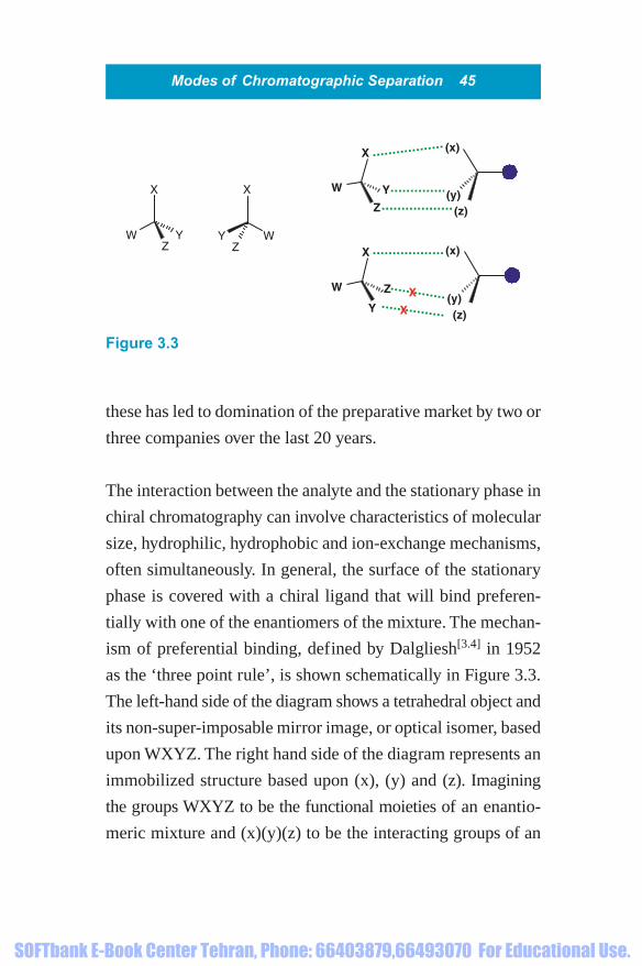
The interaction between the analyte and the stationary phase in
chiral chromatography can involve characteristics of molecular
size, hydrophilic, hydrophobic and ion-exchange mechanisms,
often simultaneously. In general, the surface of the stationary
phase is covered with a chiral ligand that will bind preferen-
tially with one of the enantiomers of the mixture. The mechan-
ism of preferential binding, defined by Dalgliesh[3.4] in 1952
as the ‘three point rule’, is shown schematically in Figure 3.3.
The left-hand side of the diagram shows a tetrahedral object and
its non-super-imposable mirror image, or optical isomer, based
upon WXYZ. The right hand side of the diagram represents an
immobilized structure based upon (x), (y) and (z). Imagining
the groups WXYZ to be the functional moieties of an enantio-
meric mixture and (x)(y)(z) to be the interacting groups of an
X
ZYW
X
ZY W
X
Z
YW
(x)
(z)(y)
(x)
(z)(y)
X
Y
W Z X
X
Figure 3.3
1856174662_ch03.qxd 1/18/06 1:53 PM Page 45
SOFTbank E-Book Center Tehran, Phone: 66403879,66493070 For Educational Use.

immobilized chiral ligand, it is easy to observe that the binding
of one enantiomer will be preferred over the other.
This ‘three point rule’was further ratified by Pirkle and House[3.5]
who stated that ‘there must be at least three simultaneous inter-
actions between a chiral stationary phase and a solute enan-
tiomer and one of these must be stereochemically dependent, if
chiral resolution is to be effected’. Some of the earliest chiral
stationary phases developed by Pirkle contain various binding
sites including, �-electron donors, �-electron acceptors and
amides or esters for hydrogen bonding. Many other chiral lig-
ands have been utilized over the ensuing years including pro-
teins, cyclodextrins, antibiotics and crown ethers.
Although they are extremely useful analytically, the protein
based stationary phases[3.6,3.7] have found little application in
preparative HPLC because they suffer from low loading cap-
acity, due primarily to the low number of active sites. The nat-
ural macrocylic molecules Cyclodextrin[3.8,3.9] and antibiotics
such as Vancomycin[3.10] have shown some promise. Synthetic
chiral crown ethers[3.11] are particularly useful for the separ-
ation of chiral primary amines.
More recently, polymeric tartaric derivatives[3.12] covalently
bound to silica are proving to be useful in preparative applica-
tions due to enhanced physical and chemical stability. How-
ever, the most extensively used media by far are based upon
46 Modes of Chromatographic Separation
1856174662_ch03.qxd 1/18/06 1:53 PM Page 46
SOFTbank E-Book Center Tehran, Phone: 66403879,66493070 For Educational Use.

Modes of Chromatographic Separation 47
modified amylase and cellulose polymers adsorbed to the sur-
face of silica[3.13]. When describing the basic concept of the
chiral stationary phase the word ‘covered’was used deliberately
since in this case, until recently, the ligand was not covalently
bound to the surface of the stationary phase. The second example
of process development described in Chapter 5 involves a chiral
separation on this type of chiral stationary phase.
There have been several useful reviews written on chiral chro-
matography over recent years but one of the most comprehen-
sive was written by Levin and Abu-Lafi in 1993[3.14].
The majority of applications utilizing ion exchange as a mode
of chromatography are generally carried out at low to medium
pressure. This approach is commonplace in the biotechnology
arena where it is predominantly used for the purification of
biological macromolecules such as proteins. However, it is worth
summarising the high pressure application of the technique
since it is particularly useful for the purification of synthetic
oligonucleotides. The DNA therapeutics market is extremely
buoyant at present and most pharmaceutical companies have
their foot in the door or are at least collaborating with a group
or company investigating oligonucleotide based drugs. The
3.4 Ion Exchange Chromatography
1856174662_ch03.qxd 1/18/06 1:53 PM Page 47
SOFTbank E-Book Center Tehran, Phone: 66403879,66493070 For Educational Use.
48 Modes of Chromatographic Separation
predicted market potential ranges from hundreds of kilograms
to multi-tonne requirements. Therefore the subsequent growth
in synthesis will be mirrored by a concurrent growth in purifi-
cation developments.
Ion exchange chromatography, as the name suggests, separates
molecules by taking advantage of a charge differential. There are
understandably two approaches to ion exchange separations, so
both cation and anion exchange stationary phases are commer-
cially available. The stationary phases are predominantly poly-
mer based and functionalized with acidic groups to produce
cation exchange materials, or basic groups to produce anion
exchangers. Cation exchange media are generally of carboxylic
acid or sulfonic acid functionality to provide weak and strong
cation exchangers, respectively. Conversely, the weak and strong
anion exchange media are typically functionalized as tertiary or
quaternary amines. Ion exchange chromatography is generally
carried out in aqueous environment where the charged com-
ponents of a mixture are desorbed from the stationary phase by
either changing the pH of the eluent or by adding a stronger
counter-ion and effectively displacing the analyte.
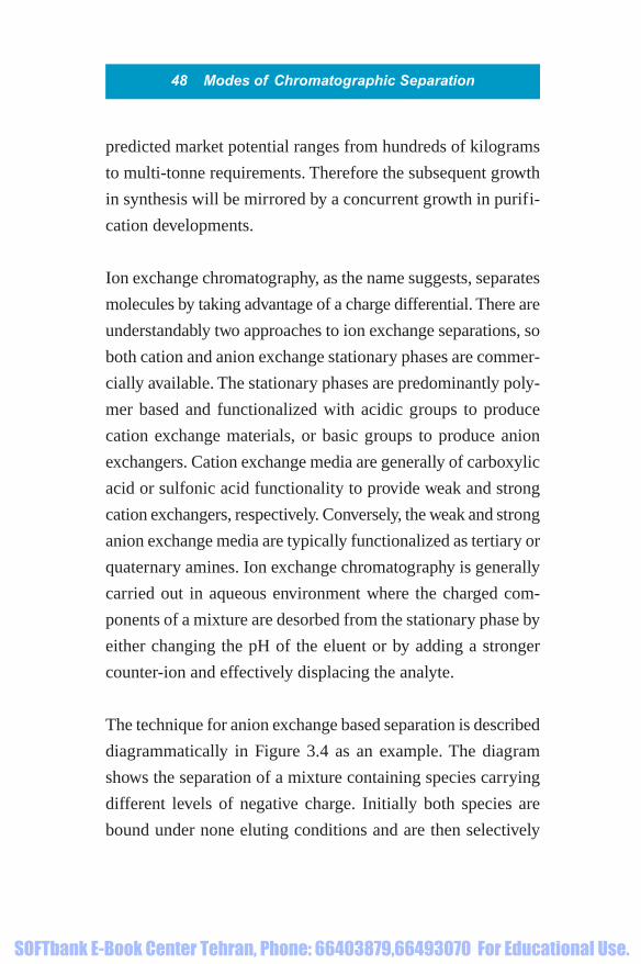
The technique for anion exchange based separation is described
diagrammatically in Figure 3.4 as an example. The diagram
shows the separation of a mixture containing species carrying
different levels of negative charge. Initially both species are
bound under none eluting conditions and are then selectively
1856174662_ch03.qxd 1/18/06 1:53 PM Page 48
SOFTbank E-Book Center Tehran, Phone: 66403879,66493070 For Educational Use.

Modes of Chromatographic Separation 49
stat
ion
ary
ph
ase
stat
ion
ary
ph
ase
stat
ion
ary
ph
ase
stat
ion
ary
ph
ase
add mixture
add eluting buffer
weakly boundspecies elutes
strongly boundspecies elutes
Figure 3.4
1856174662_ch03.qxd 1/18/06 1:53 PM Page 49
SOFTbank E-Book Center Tehran, Phone: 66403879,66493070 For Educational Use.

50 Modes of Chromatographic Separation
desorbed as the concentration of a more strongly bound anion
is increased.
The mixture could be eluted by decreasing the pH of the elu-
ent. However, it is usually easier to elute by increased salt con-
centration since this is simpler to control.
Invest in a conductivity meter!
If the ionic strength of the sample solution
is much higher than that of the starting
conditions the mixture will not bind. A simple
dilution can save a lot of lost time and reduce
frustration.
The basic structure of an oligonucleotide is shown in Figure 3.5.
The major impurities in synthetic oligonucleotides are usually
nucleoside deletions and occasionally insertions. The impur-
ities will therefore have a different charge density compared to
the target molecule. The longer, more highly charged molecules
have a stronger retention, so deletions will elute earlier than the
target molecule which will, in turn, elute earlier than nucleo-
side insertions.
1856174662_ch03.qxd 1/18/06 1:53 PM Page 50
SOFTbank E-Book Center Tehran, Phone: 66403879,66493070 For Educational Use.

Modes of Chromatographic Separation 51
Oligonucleotides are normally purified by anion exchange
chromatography. The crude mixture is immobilized at high pH
and often eluted by increased concentration of a salt, such as
sodium chloride. It is advantageous to add 15–20% of a miscible
organic solvent, such as acetonitrile or ethanol, to counteract
any reversed phase interaction with the underlying polymer
backbone. Figure 3.6 shows a typical example of a crude syn-
thetic oligonucleotide containing 18 bases, separated on a
strong anion exchange resin.
When purifying oligonucleotides it is particularly useful to use
sample self displacement chromatography since the required
component of the mixture is generally the later eluting moiety.
With this approach the column loading is increased to such a
point that the more strongly retained component displaces the
Adenosine Guanosine
Cytidine Thymine
Nuc
CH3
O
O N
HN
Nuc
O
NH2N
NHN
NNuc
NH2
N
NN
N
Nuc
NH2
O
N
NR
R
R
R
OHOP
OP
OHOP
O
HOO
O
O
O
O
OO
HO
HO
OO
R �
Figure 3.5
1856174662_ch03.qxd 1/18/06 1:53 PM Page 51
SOFTbank E-Book Center Tehran, Phone: 66403879,66493070 For Educational Use.

52 Modes of Chromatographic Separation
less strongly adsorbed species. The technique is described in
detail in Chapter 5.
One of the drawbacks of ion exchange chromatography is the
need for a secondary technique to remove inorganic salts from
the purified product. Desalting can often be performed by
ultrafiltration, solid phase extraction or by gel filtration. The
latter mode of separation is described briefly in Section 3.5.
Column : PL-SAX, 8 µm, 1000 ÅGradient : 0–100%B over 20 minFlow rate : 1 cm3/minBuffers : A � 0.05 mol/dm3 NaOH (in 4:1 v/v water/ethanol) B � 0.05 mol/dm3 NaOH plus 3 mol/dm3 NaCl (in 4:1 v/v water/ethanol)
4
0
100
200
300
400mV
500
600
700
8Minutes
12 16� � � �� �
Figure 3.6
1856174662_ch03.qxd 1/18/06 1:53 PM Page 52
SOFTbank E-Book Center Tehran, Phone: 66403879,66493070 For Educational Use.

Modes of Chromatographic Separation 53
This technique is often referred to under several headings such
as gel filtration, gel permeation, or size exclusion chromatog-
raphy. In its simplest form, gel filtration, it is often used to desalt
solutions and is regularly used to compliment ion exchange sep-
arations. In more complex separations it can be used to sep-
arate proteins of different size or shape. This mode of separation
is rarely performed at high pressure and is often reserved for
separating mixtures, as the title suggests, by taking advantage
of the differing size.
Why discuss this approach if it is limited to low pressure oper-
ation? The ongoing and future development of recombinant
processes for the preparation of biopharmaceuticals will require
a concurrent high performance approach to separation of pro-
teins from fermentation broths and from salts. The productivity
of current approaches using low pressure systems or ultrafil-
tration will be insufficient to cope with the long-term demand.
It is inevitable that manufacturers will develop high perform-
ance techniques and high pressure packing media. It is pos-
sible to envisage the use of continuous techniques such as SMB
chromatography in size exclusion mode[3.15].
The column packing media used in size exclusion chromatog-
raphy is available in various pore sizes, designed to exclude
3.5 Exclusion Chromatography
1856174662_ch03.qxd 1/18/06 1:53 PM Page 53
SOFTbank E-Book Center Tehran, Phone: 66403879,66493070 For Educational Use.

54 Modes of Chromatographic Separation
larger molecules. For simple desalting of a protein the separation
works by excluding the biological macromolecule from the pores
of the packing media and allowing the salt to penetrate the pores,
delaying its elution. Clearly the protein is not retained and sim-
ply follows the path of convectional flow through the interstitial
spaces between the particles. In a slightly more complex situ-
ation, often referred to as gel permeation chromatography, the
particles have varying pore sizes designed to allow penetration
by the large species. This technique can be used to separate
proteins and protein aggregates of various sizes and, as such, is
likely to be important in the growing recombinant market.
Packing Media! What happened to ‘Stationary Phase’?
In size exclusion chromatography the
‘Stationary Phase’ is the solvent inside the
pores of the column packing media.
Conversely the ‘Mobile Phase’ is the solvent
in the interstitial spaces.
Again, until recently, affinity chromatography has been limited
to low pressure operations. However, as described above for size
3.6 Affinity Chromatography
1856174662_ch03.qxd 1/18/06 1:53 PM Page 54
SOFTbank E-Book Center Tehran, Phone: 66403879,66493070 For Educational Use.

Modes of Chromatographic Separation 55
exclusion, affinity chromatography has a special place in the
purification of biological macromolecules. The growing popu-
larity of biopharmaceuticals, especially those derived from
recombinant processes, will almost certainly require major
developments in high pressure stationary phases for affinity
chromatography.
This mode of separation, as the name suggests, uses stationary
phases with a special affinity for a specific analyte. The affin-
ity ligand immobilized on the stationary phase varies dramat-
ically from peptide, to protein, to oligonucleotide, to monoclonal
antibody. In some cases the target molecule is labelled with an
affinity tag to simplify the separation. This approach is com-
mon in the synthesis of recombinant proteins where the system
can be engineered so that the target biomolecule expresses a
tag such as polyhistidine. A stationary phase functionalized
with aminodiacetic acid and nickel chelate is then used to fish
out the required molecule by chelating with the polyhisti-
dine tag.
Existing stationary phases used in this area are usually soft gels
that often suffer from low loading capacity brought about by the
inability of biological macromolecules to penetrate the matrix.
The most likely progress in this arena over the forthcoming
1856174662_ch03.qxd 1/18/06 1:53 PM Page 55
SOFTbank E-Book Center Tehran, Phone: 66403879,66493070 For Educational Use.

56 Modes of Chromatographic Separation
years will be in the development of macroporous media with
high loading capacities, and the mechanical rigidity essential
for operation at high pressure.
The technique of affinity chromatography was described in
some detail by Lowe and Dean in a text published in 1974[3.16].
Have you realized?
Chiral chromatography is a variant of Affinity
Chromatography.
1856174662_ch03.qxd 1/18/06 1:53 PM Page 56
SOFTbank E-Book Center Tehran, Phone: 66403879,66493070 For Educational Use.

4How to get
started
1856174662_ch04.qxd 1/18/06 3:46 PM Page 57
SOFTbank E-Book Center Tehran, Phone: 66403879,66493070 For Educational Use.

This page intentionally left blank
SOFTbank E-Book Center Tehran, Phone: 66403879,66493070 For Educational Use.

For process scale operations it is normal for users to pack sta-
tionary phases in their own column hardware. The most com-
mon equipment available is based on the dynamic axial
compression system invented by Couillard[4.1], subsequently
assigned to, and first marketed by Prochrom (now NovaSep).
The original patents on this technology have now expired so
this type of column format is now available from a range of
suppliers. In general, this simple but very effective technology
involves the use of a moving piston as one of the column end
fittings thereby allowing a constant compression of the packed
bed with a dynamic removal of column voids. Examples of
preparative DAC columns and HPLC systems are found in
Figures 4.1 and 4.2. Figure 4.1 shows a 20 cm diameter DAC
column, which can be seen on the left of the photograph.
Figure 4.2 shows an industrial scale column with an internal
diameter of 60 cm.
Other column designs have been developed, including radial
compression[4.2] and annular expansion[4.3]. The radial com-
pression system originally developed by Waters, and now mar-
keted by Biotage, uses flexible polymeric cartridges packed
with stationary phase. The cartridge is housed in a cylinder and
the axial compression is generated by applying external pressure
to the cartridge. In the annular expansion columns a tapered
Chapter Four
4.1 Packing a Column
1856174662_ch04.qxd 1/18/06 3:46 PM Page 59
SOFTbank E-Book Center Tehran, Phone: 66403879,66493070 For Educational Use.

60 How to Get Started
Figure 4.2 Courtesy of Jerome Theobald, NovaSep SAS
Figure 4.1 Courtesy of Jerome Theobald, NovaSep SAS
1856174662_ch04.qxd 1/18/06 3:46 PM Page 60
SOFTbank E-Book Center Tehran, Phone: 66403879,66493070 For Educational Use.

rod runs through the column and compresses the stationary
phase against the walls as the rod is pushed into the column,
providing both axial and radial compression.
This text will concentrate on the methodology used to pack
DAC based columns. There are two basic ways of packing
these columns that are determined by the design of the column
format. The two systems normally available use either a short
column with a detachable column extension (Figure 4.3), the
How to Get Started 61
reservoir
column
piston/end fitting
end fitting
Figure 4.3 Schematic diagram of DAC column
1856174662_ch04.qxd 1/18/06 3:46 PM Page 61
SOFTbank E-Book Center Tehran, Phone: 66403879,66493070 For Educational Use.

combined volume of which is sufficient to hold the total slurry
volume, or a long column, large enough to hold the total vol-
ume of the stationary phase slurry (Figure 4.4).
When using the column type shown in Figure 4.3 the reservoir,
or column extension is left in place while the slurry is added
and removed later. With the column type shown in Figure 4.4
62 How to Get Started
column
piston/end fitting
end fitting
Figure 4.4 Schematic diagram of DAC column
1856174662_ch04.qxd 1/18/06 3:46 PM Page 62
SOFTbank E-Book Center Tehran, Phone: 66403879,66493070 For Educational Use.

the fixed end fitting is normally, though not exclusively, at the
bottom of the column and the slurry is added prior to inserting
the piston. In instances where the piston is at the bottom of the
column the actual compression of the system moves and dis-
turbs the bed often leading to less efficient packing.
Column packing protocol for column type 1
(Figure 4.3)
This protocol will concentrate on the methodology used to
pack the column type shown in Figure 4.3. The basic layout
normally includes a short column with a detachable column
extension, the combined volume of which is sufficient to hold
the total slurry volume.
When using the column type shown in Figure 4.3 the reservoir,
or column extension is left in place while the slurry is added
and reservoir removed later.
Slurry concentration
The recommended solvents for various stationary phases vary
from one manufacturer to the next and will depend upon
the stationary phase being packed. However, the concentration
of stationary phase in solvent is generally in the region of 1 kg
How to Get Started 63
1856174662_ch04.qxd 1/18/06 3:46 PM Page 63
SOFTbank E-Book Center Tehran, Phone: 66403879,66493070 For Educational Use.

of stationary phase in 2–3 dm3 of solvent for silica based
stationary phases. Polymeric stationary phases are less dense
than silica based media so a dilution of 1 kg in 4–6 dm3 of solv-
ent is recommended.
Slurry and column preparation
Calculate the total volume of the column plus the packing
reservoir in order to determine the total volume (volume A) of
the required slurry. Determine the amount of stationary phase
required to pack the required bed length (the packing density
of polymerics is generally �0.3 g/cm3 and the density of silica
based media is generally �0.6 g/cm3). Add the appropriate
amount of stationary phase to a suitable container and dilute
with the chosen solvent to ‘volume A’. Ensure that the slurry is
efficiently mixed either manually or by gentle mechanical agi-
tation. Once a homogeneous slurry is obtained, halt the agita-
tion and leave the slurry to stand overnight to allow the
stationary phase to de-gas.
Set up the column with the packing reservoir in place. Attach a
vacuum line and solvent collection vessel to the bottom of the
column. Do not apply a vacuum at this stage. Re-suspend the
stationary phase either manually or by gentle mechanical agi-
tation then pour the slurry, without stopping, into the column-
reservoir assembly. It is essential that the slurry is added
64 How to Get Started
1856174662_ch04.qxd 1/18/06 3:46 PM Page 64
SOFTbank E-Book Center Tehran, Phone: 66403879,66493070 For Educational Use.

as quickly as possible to avoid settling. A pause of even a few
seconds during pouring the slurry will lead to a break in the
column bed and subsequently to poor chromatography.
Apply a vacuum to the outlet of the column and draw off the
solvent until it is a few millimetres above the bed surface.
Remove the vacuum line and plug the bottom column outlet.
Remove the column reservoir and attach the column end fit-
ting. Attach a waste solvent line to the top end fitting (with the
bottom fitting still plugged). Compress the column until the
packing pressure recommended by the column manufacturer
is achieved (typically 60–100 bar). The column is now ready
for equilibration in the solvents required for the separation.
Although the position of the piston can often be locked it is
actually best kept under constant pressure in order to maintain
a well packed bed.
Column packing protocol for column type 2
(Figure 4.4)
Although the slurry concentration and process for the prepar-
ation of the slurry remains the same, the protocols for column
packing differ slightly due to the general layout. In this system
the column length accommodates the total slurry volume.
How to Get Started 65
1856174662_ch04.qxd 1/18/06 3:46 PM Page 65
SOFTbank E-Book Center Tehran, Phone: 66403879,66493070 For Educational Use.

The bottom fitting of the column is plugged and the slurry
poured in as before. The piston is then inserted with the top
fitting attached to a waste solvent tank. As the piston pressure
is increased the solvent in the column is excluded. It is not
essential to plug the bottom fitting with either column design
as long as the waste solvent, which is under pressure, is cap-
tured. However, plugging the bottom frit improves packing
near to the top of the column bed as solvent is excluded.
In both cases the column should not be pressurized beyond the
manufacturer’s recommendations.
What use would a ‘practical handbook’ be if it did not tell you
what you need and where to put it? The guidelines given here
are provided purely as an indicative potential of the capacity of
a certain column size and the estimated footprint the column
and its ancillary equipment will occupy. The capacity of the
stationary phase will depend upon the mode of chromatog-
raphy and the method of operation. For instance, the loading
capacity of reversed phase and chiral stationary phases is gen-
erally at least half that of a normal phase media. This is not
meant to imply that normal phase chromatography is more
4.2 What and Where!
66 How to Get Started
1856174662_ch04.qxd 1/18/06 3:46 PM Page 66
SOFTbank E-Book Center Tehran, Phone: 66403879,66493070 For Educational Use.
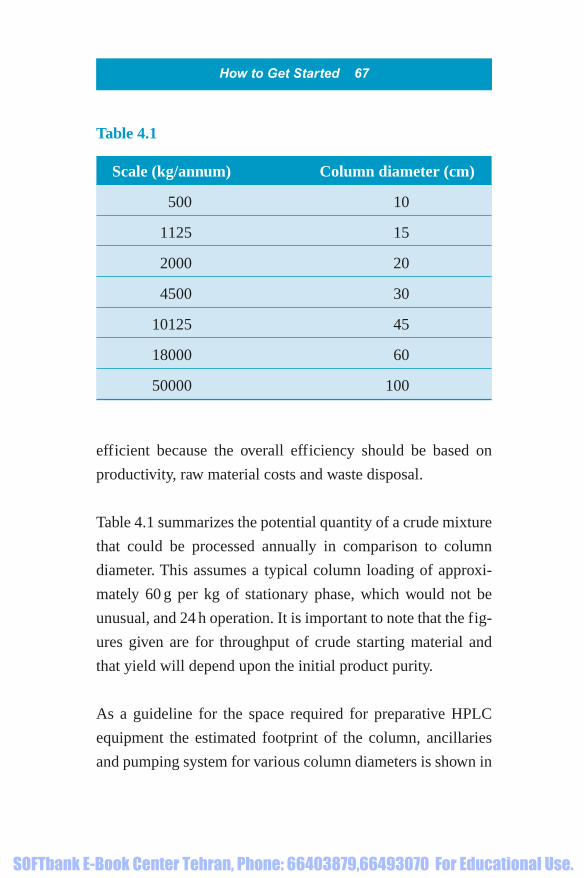
efficient because the overall efficiency should be based on
productivity, raw material costs and waste disposal.
Table 4.1 summarizes the potential quantity of a crude mixture
that could be processed annually in comparison to column
diameter. This assumes a typical column loading of approxi-
mately 60 g per kg of stationary phase, which would not be
unusual, and 24 h operation. It is important to note that the fig-
ures given are for throughput of crude starting material and
that yield will depend upon the initial product purity.
As a guideline for the space required for preparative HPLC
equipment the estimated footprint of the column, ancillaries
and pumping system for various column diameters is shown in
How to Get Started 67
Scale (kg/annum) Column diameter (cm)
500 10
1125 15
2000 20
4500 30
10125 45
18000 60
50000 100
Table 4.1
1856174662_ch04.qxd 1/18/06 3:46 PM Page 67
SOFTbank E-Book Center Tehran, Phone: 66403879,66493070 For Educational Use.
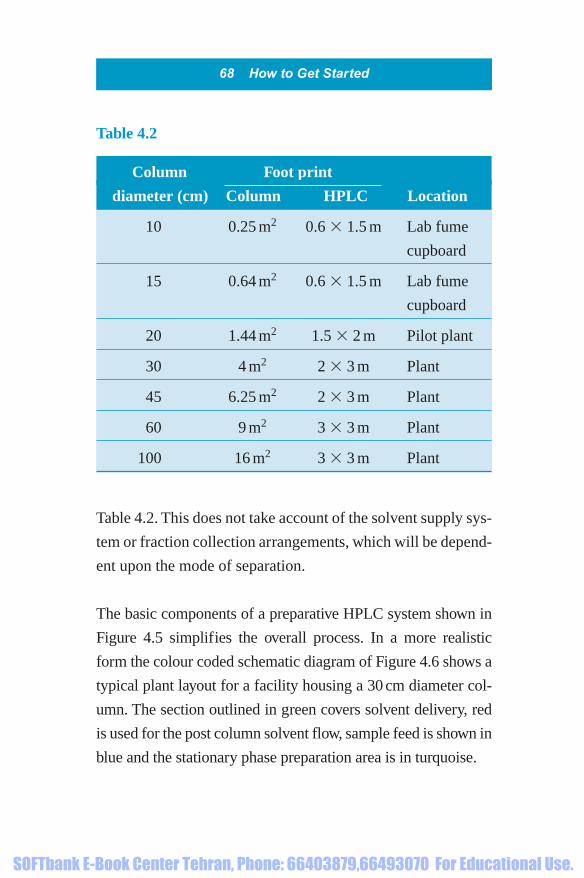
Table 4.2. This does not take account of the solvent supply sys-
tem or fraction collection arrangements, which will be depend-
ent upon the mode of separation.
The basic components of a preparative HPLC system shown in
Figure 4.5 simplifies the overall process. In a more realistic
form the colour coded schematic diagram of Figure 4.6 shows a
typical plant layout for a facility housing a 30 cm diameter col-
umn. The section outlined in green covers solvent delivery, red
is used for the post column solvent flow, sample feed is shown in
blue and the stationary phase preparation area is in turquoise.
68 How to Get Started
Column Foot print
diameter (cm) Column HPLC Location
10 0.25 m2 0.6 � 1.5 m Lab fume
cupboard
15 0.64 m2 0.6 � 1.5 m Lab fume
cupboard
20 1.44 m2 1.5 � 2 m Pilot plant
30 4 m2 2 � 3 m Plant
45 6.25 m2 2 � 3 m Plant
60 9 m2 3 � 3 m Plant
100 16 m2 3 � 3 m Plant
Table 4.2
1856174662_ch04.qxd 1/18/06 3:46 PM Page 68
SOFTbank E-Book Center Tehran, Phone: 66403879,66493070 For Educational Use.

The system shown is capable of performing a quaternary
gradient and shows all of the elements to be considered for
industrial scale separations. For instance, a solvent reservoir
size of 1–2 m3 would allow continuous operation for several
hours. Separations carried out at this scale will be extremely
well-defined with respect to fraction size and point of collec-
tion so very few fraction collection vessels would be required.
It would seem a rather pointless exercise planning the installa-
tion of a preparative HPLC system without considering the
process to recover the product from the chromatographic elu-
ent. There is no simple answer to the question since it will
4.3 Product Recovery
How to Get Started 69
pump
column
detector
recorder
fraction collector
sample load
reservoir
Figure 4.5
1856174662_ch04.qxd 1/18/06 3:46 PM Page 69
SOFTbank E-Book Center Tehran, Phone: 66403879,66493070 For Educational Use.

70H
ow
to G
et Started
1 m3
SP
N2
FME32
VEA3 VE1
VC1
VC2VC3
VC4
FP
N2
VIHP
Filter
VAP1
FME4
VEA4
FMPE
RI
UV
EP
V11
VBF1
VBP1VPE2
VPE3
VBF2
FME
VEA2
VR2
AXIALCOMPRESSION
COLUMN
200 dm3200 dm3
2 m3
1 m3
2 m3
4 m3
4 m3
VacuumPALL FILTER STATIC
MIXER
Solvent fromLEB
Stationaryphase slurrypreparation
tank
STV
VBP2
V13V14
VF2
VF1FilterFilter
VR1
HEATEXCHANGER
V12
Guardcolumn
Dissolvedproduct from
LEB
Crudefeedtank
Pre-filtered
feed tank
VPC2
VPC1
SPtSPt
SPt SPt
Figure 4.6
1856174662_ch04.qxd 1/18/06 3:46 PM Page 70
SOFTbank E-Book Center Tehran, Phone: 66403879,66493070 For Educational Use.

depend on the nature of the product and the solvents to be
removed.
For biological macromolecules such as peptides, proteins and
oligonucleotides, which are generally purified by reversed
phase chromatography, the difficulty lies in the removal of
water. Lyophilization is a very mild option on a small to inter-
mediate scale, but this becomes impractical and expensive
when the volumes reach several hundred litres. The validation
of a freeze drying process can also be very complex and the
process reproducibility is poor, often leading to varying levels
of residual solvent in the final product. For cGMP processes
lyophilization from bottles and flasks does not provide suffi-
cient reproducibility and instruments with temperature
controlled shelves can be expensive. Wiped film evaporation is
a useful complimentary technique for concentration of solu-
tions prior to lyophilization.
How to Get Started 71
Ready packaged!
When lyophilising from trays in a shelf freeze
dryer try transferring the solution to Gortex
bags before lyophilization.
1856174662_ch04.qxd 1/18/06 3:46 PM Page 71
SOFTbank E-Book Center Tehran, Phone: 66403879,66493070 For Educational Use.

Spray drying can be a useful option for large volumes of aque-
ous solvents and is used regularly for the recovery of peptides
and proteins. However, before investing in spray drying equip-
ment it is worth confirming the stability of the product to the
process. When using reversed phase chromatography for purifi-
cation of small organics it is often easy to remove the polar
modifier by rotary evaporation and extract the product using
an immiscible solvent. The predominantly organic solvents
used for normal phase separations can be removed by trad-
itional means of evaporation including wiped film and rotary
evaporators.
For those considering the development of a preparative separ-
ation with the long-term objective of using preparative HPLC
as part of a manufacturing route, the costs associated with the
routine operation will be a major focus of the decision-making
process. The ultimate value of the product and the costs of
developing alternative purification methods will have to be
taken into account and for many targets there may be no alter-
native to HPLC. For the purification of synthetic peptides
there is no single technique that will provide the target mol-
ecule at a higher purity than reversed phase chromatography.
The same can be said when using a combination of anion
4.4 Productivity
72 How to Get Started
1856174662_ch04.qxd 1/18/06 3:46 PM Page 72
SOFTbank E-Book Center Tehran, Phone: 66403879,66493070 For Educational Use.

exchange and reversed phase techniques for the purification of
synthetic oligonucleotides. At the other end of the scale, sep-
aration of a racemic mixture by chiral chromatography can
sometimes be avoided by an asymmetric synthesis. However, if
the time and person-power taken to develop asymmetric chem-
istry is taken into account, it may be worth reconsidering
preparative HPLC since the establishment of a chromato-
graphic process is generally extremely rapid by comparison.
The productivity of a typical reversed phase purification of a
peptide is summarized in Table 4.3. For this particular separ-
ation the column loading is relatively low and a large number
of separations are carried out in order to deliver the annual
production target. On the face of it, the productivity of this
separation is poor; in practice the column size was chosen to
balance the output with the rate of synthesis of crude peptide.
The actual combined costs of synthesis and purification for
this particular peptide was only a tiny fraction of the value of
the formulated drug. On occasions it may be better to purify a
valuable product in smaller portions rather than risk a propor-
tionally high loss from failed separation.
Table 4.4 shows the comparative data for purification of a trad-
itional small molecule by normal phase chromatography.
How to Get Started 73
1856174662_ch04.qxd 1/18/06 3:46 PM Page 73
SOFTbank E-Book Center Tehran, Phone: 66403879,66493070 For Educational Use.

74 How to Get Started
Table 4.3
Column diameter 15 cm
Column length 25 cm
Stationary phase 3.5 kg
Eluent (water/acetonitrile) 78:22
Column loading 40 g
Cycle time 60 min
Solvent consumption/kg of 600 dm3
crude processed
Annual production 40 kg
Table 4.4
Column diameter 100 cm
Column length 25 cm
Stationary phase 155 kg
Eluent (organic) 100%
Column loading 15.5 kg
Cycle time 60 min
Solvent consumption/kg of 130 dm3
crude processed
Annual production 36,000 kg
1856174662_ch04.qxd 1/18/06 3:46 PM Page 74
SOFTbank E-Book Center Tehran, Phone: 66403879,66493070 For Educational Use.
This is a relatively simple separation, so column loading is rela-
tively high and solvent consumption per kilogram of crude
material processed is low.
How to Get Started 75
It is important to consider all components of a purification
when deciding which mode of chromatography to use for a
particular separation. For example, when comparing normal
phase with reversed phase chromatography the loading cap-
acity of the latter is generally lower. However, the solvents
used for reversed phase chromatography are predominantly
aqueous and consequently are normally cheaper. The station-
ary phases used for reversed phase separations are, on average,
twice the price of the normal phase equivalent but the resolv-
ing power is generally much greater. In some instances, as is
the case with most biological molecules, recovery of the prod-
uct from the aqueous eluent can be tedious. It can also be said
that most biological molecules would not purify readily in
purely organic solvents by normal phase chromatography.
A sledgehammer to crack a nut!
The capital investment to establish a plant
capable of handling a 1 m diameter column will
be vast compared to the straightforward task
of setting up a 15 cm diameter column in a
laboratory.
1856174662_ch04.qxd 1/18/06 3:46 PM Page 75
SOFTbank E-Book Center Tehran, Phone: 66403879,66493070 For Educational Use.

This page intentionally left blank
SOFTbank E-Book Center Tehran, Phone: 66403879,66493070 For Educational Use.
5Process
development andoptimization
1856174662_ch05.qxd 1/18/06 8:41 AM Page 77
SOFTbank E-Book Center Tehran, Phone: 66403879,66493070 For Educational Use.

This page intentionally left blank
SOFTbank E-Book Center Tehran, Phone: 66403879,66493070 For Educational Use.

Clearly it is not possible to describe every technique, or vari-
ation in a particular mode of chromatography, so this chapter
will concentrate on the most dominant approaches to opti-
mization of preparative HPLC. The objective here is to maxi-
mize the column load and to minimize mobile phase wastage
allowing the purification of the largest amount of target in the
minimum space.
Two case studies will be shown here to demonstrate the devel-
opment of purification processes in both overload and reso-
lution based separations[5.1]. The first example summarizes the
purification of a synthetic peptide by overload chromatog-
raphy, or more accurately described as sample self displace-
ment chromatography. The techniques applied to this separation
are applicable to any molecule and can be applied to all modes
of chromatography, with the exception of size exclusion
chromatography.
In the second example the separation of two optical isomers by
batch chromatography using ‘box car’ injections demonstrates
one approach to purification by chiral chromatography.
The purification of synthetic peptide objectives is open to many
modes of separation due to the hydrophilic, hydrophobic and
5.1 Sample Self Displacement for Purification
of a Peptide
Chapter Five
1856174662_ch05.qxd 1/18/06 8:41 AM Page 79
SOFTbank E-Book Center Tehran, Phone: 66403879,66493070 For Educational Use.

charged nature of amino acid side-chains. Employment of ion-
exchange, hydrophilic interaction, normal phase and reversed
phase modes of chromatography all seem perfectly viable.
Though ion-exchange has its place in peptide purification,
the complex and subtle nature of the impurities observed in
peptides prepared by the solid phase approach dictates the use
of high performance techniques offered by Normal and
Reversed Phase modes of operation.
Synthetic peptides often contain impurities with no charge dif-
ference, with chemical modifications at side-chains, amino acid
deletions and insertions, or epimeric impurities arising from
racemization. This complexity has led to the development of
many Reversed Phase media with carefully controlled particle
size and pore size that result in high resolution under gradient
elution. Many of these stationary phases are based on a silica
matrix chemically bonded with alkyl chains such as C8 or C18.
Though considerable effort has been made to mask the silica
matrix, these supports suffer from an inherent base instability
at levels above pH 9. In addition, in most cases the fragile
nature of the silica matrix also reduces the lifetime of these
media in high pressure systems. This is a particular problem
for wide-pore, silica based stationary phases with a mean pore
size of �200 Å and leads fracture of the media, generation of
fines and eventual blockage of column frits. Conversely, for
Reversed Phase chromatography, polymeric stationary phases
offer both chemical and mechanical stability with none of the
80 Process Development and Optimization
1856174662_ch05.qxd 1/18/06 8:41 AM Page 80
SOFTbank E-Book Center Tehran, Phone: 66403879,66493070 For Educational Use.

underlying traits of silica which is, by its very nature, a Normal
Phase base matrix. Particle fragility and the secondary inter-
actions caused by the cationic, hydrophilic nature of silica are
not observed.
Peptides often have a low mobility in solution so a small par-
ticle size and uniform pore shape are essential for effective mass
transfer. The tertiary structure of peptides differ dramatically
from one molecule to the next so stationary phases that offer a
range of pore sizes is prerequisite. Relatively small peptides
containing 20–30 amino acids can often have a comparatively
large radius of gyration in solution compared to some globular
peptide structures containing significantly more amino acids.
For instance, the radius of gyration of the Calcitonin peptides,
which contain 32 amino acids, is �20 Å whereas the diameter
of Insulin, a 54 amino acid peptide, is �15 Å. As a conse-
quence, the Calcitonins show poor mass transfer in stationary
phases with a mean pore diameter of 100 Å, whilst Insulin is
readily, and usually, purified at high load on the same material.
For an efficient and cost effective purification it is therefore
essential to choose the appropriate surface characteristics, pore
size and flow rate for each peptide.
For analytical separations it is important to run a full gradient
based separation since this will recognize and allow subse-
quent identification of the majority of impurities present in the
crude peptide. This impurity identification may eventually
Process Development and Optimization 81
1856174662_ch05.qxd 1/18/06 8:41 AM Page 81
SOFTbank E-Book Center Tehran, Phone: 66403879,66493070 For Educational Use.

lead to improvements in the synthetic strategy by identifying
specific shortfalls in the chemistry and ultimately to a higher
yield coupled with lower manufacturing costs. Gradient elu-
tion is also particularly efficient when it comes to analysing
low level impurities running close to the target peptide on the
chromatogram that might otherwise be lost in the background
noise of an isocratic separation.
In cases where mass transfer is rapid, as is the case with most
small molecule separations, then isocratic elution can offer
advantages such as automatic fraction reprocessing and solvent
recycle. However, with larger synthetic objectives the rate of
mass transfer is comparatively low so isocratic elution leads to
band broadening and subsequently to recovery of the peptide at
high dilution. Most preparative HPLC based peptide separations
are carried out under gradient and overload conditions that
allow for maximum throughput in terms of time and quantity.
Once the stationary phase and gradient conditions have been
selected there are two options for practical applications. The
first option is to maximize the column loading such that a rea-
sonable level of resolution is maintained allowing peak skim-
ming to achieve the required purity. The second option is to
overload the column to such an extent that the main compon-
ent displaces earlier running components of a mixture.
82 Process Development and Optimization
1856174662_ch05.qxd 1/18/06 8:41 AM Page 82
SOFTbank E-Book Center Tehran, Phone: 66403879,66493070 For Educational Use.

Whilst the former process will clearly yield material of the
required purity it is not normally suitable for larger scale sep-
arations of synthetic peptides since column loadings will
maximize at 1–2 mg/cm3. In sample self-displacement chro-
matography the load is steadily increased until the main
component displaces the less strongly bound impurity whilst
minimizing the ‘tag along’ effect, of more strongly bound
impurities, often observed with this mode of operation. In
this approach the column loadings tend to maximize at
50–200 mg/cm3, whilst the separation is effected in a similar
time-scale. It is often beneficial to reverse the elution order of
impurities, by a change of stationary phase, buffer, or pH, in
order to allow self-displacement of these components of the
mixture.
The self-displacement approach to purification of a synthetic
peptide containing 25 amino acids is shown below[5.1]. The
analytical HPLC trace (Figure 5.1) shows the impurity peak
(A), which is displaced by the main component (B) in the
demonstration.
The anticipated effect of column overload and eventual effect
of displacement is shown diagrammatically in Figure 5.2.
The size of the ‘blue’ overlapping area is governed by the col-
umn efficiency. The more efficient the column, the smaller the
overlap (Figure 5.3).
Process Development and Optimization 83
1856174662_ch05.qxd 1/18/06 8:41 AM Page 83
SOFTbank E-Book Center Tehran, Phone: 66403879,66493070 For Educational Use.

84 Process Development and Optimization
A
B
7.94
12.1
410.9
2
9.16
6.985.
62.4
111.0
Analytical HPLC trace
Figure 5.1 Analytical HPLC of synthetic peptide (25 amino
acids)
Analytical loading
Anticipated effectof increasedloading
Actual effect ofincreased loading
Figure 5.2 Observations during overload
1856174662_ch05.qxd 1/18/06 8:41 AM Page 84
SOFTbank E-Book Center Tehran, Phone: 66403879,66493070 For Educational Use.

The effect of a comparatively low loading (1.4 g) on a semi-
preparative column (42 m � 250 mm) packed with PLRP-S
(8 �m, 300 Å pore) is shown in Figure 5.4. The blue line
represents the actual UV trace obtained during the separation,
the green line shows the relative purity of the main component
(B) in relation to the impurity (A) and the red line represents
the relative purity of the impurity (A) in relation to the main
component (B).
Process Development and Optimization 85
High resolution column Low resolution column
Figure 5.3
40 43 46 49 52 55 58 61 64 67 70 73 76 80 85 88 91 94 97 100
103
106
109
%B%ATotal
1.4 g load on 42 mm diameter column
Figure 5.4
1856174662_ch05.qxd 1/18/06 8:41 AM Page 85
SOFTbank E-Book Center Tehran, Phone: 66403879,66493070 For Educational Use.

It is clear that at this stage, the impurity is neither resolved or
displaced. A gradual increase in loading eventually resulted in
self-displacement and the optimum load for this particular mol-
ecule was �6 g on the 42 mm diameter column (Figure 5.5).
Again the blue line represents the UV trace obtained during the
separation and the green and red lines represent the relative
levels of main component and impurity, respectively. Self-
displacement is characterized by the sharp increase in the level
of impurity in the early running fractions whilst in this example
the material collected between 89 and 130 minutes fell within
the required specification.
Self-displacement will operate with almost any mode of chro-
matography including reversed phase as demonstrated above,
normal phase, chiral and ion-exchange. The following pro-
cedures provide a generic approach to development of a
86 Process Development and Optimization
6 g load on 42 mm diameter column
21 24 27 30 33 36 39 42 45 48 51 65 80 87 90 93 100
112
130
136
144
160
180
210
%B%ATotal
Figure 5.5
1856174662_ch05.qxd 1/18/06 8:41 AM Page 86
SOFTbank E-Book Center Tehran, Phone: 66403879,66493070 For Educational Use.
separation including choice of gradient, loading studies and
flow rate optimization.
The first two stages can be performed on an analytical column.
However, flow rate optimization is best performed on a col-
umn of at least 50 mm diameter in order to compensate for
friction and column wall effects. The passage of solvent over
particles in a packed HPLC column generates friction, which
in turn produces heat resulting in a rise in temperature of the
eluent. It is not uncommon with column lengths of 25 cm to
see a temperature gradient of 2–3°C between inlet and outlet
of the column. Though this does not sound phenomenal, when
considered in conjunction with solvent cooling at the column
walls, it can have a considerable effect on a chromatographic
separation.
As the eluent passes through the column the heat generated
reduces the viscosity of the solvent. Cooling of the solvent at
the column walls by conduction reduces viscosity in this vicin-
ity resulting in a parabolic flow of eluent through the column,
with solvent closer to the centre of the column moving faster
than solvent at the periphery. There are several ways to reduce
this effect, including heating the solvent in order to minimize
the viscosity gradient and heating the column walls to reduce
cooling by conduction.
Process Development and Optimization 87
1856174662_ch05.qxd 1/18/06 8:41 AM Page 87
SOFTbank E-Book Center Tehran, Phone: 66403879,66493070 For Educational Use.

The simplest and often the most cost effective way to combat
friction is to reduce flow rate to a minimum. By no coinci-
dence, this often leads to an increase in the efficiency of
a separation since in many circumstances for preparative
purifications, the less experienced have followed a linear
scale-up from analytical column flow rates. In an ideal world
each separation should, at some stage, involve a flow rate opti-
mization. The fundamental principles behind this are dis-
cussed by JJ van Deemter[5.2] in what is probably the most
cited paper in the history of chromatography. In summary, this
suggests doing a graphical plot of separation efficiency versus
flow rate and is particularly important for peptide purification
where mass transport is comparatively slow. The van Deemter
equation in simplified form can be represented as:
where, H � height equivalent to a theoretical plate, and
� � flow rate.
Optimum flow rates are achieved at the lowest value for H. The
terms A, B and C are constants relating to eddy diffusion, lon-
gitudinal diffusion and to mass transfer of the analyte.
The typical appearance of a van Deemter plot is shown in
Figure 5.6. At low flow rates an axial longitudinal diffusion
results in band broadening (the analyte can diffuse against the
H AB
C� ��
� �
88 Process Development and Optimization
1856174662_ch05.qxd 1/18/06 8:41 AM Page 88
SOFTbank E-Book Center Tehran, Phone: 66403879,66493070 For Educational Use.

flow). Whilst at high flow rates the tortuous path followed by
the eluent around the particles creates eddies, a resultant poor
longitudinal diffusion and inefficient mass transfer lead to
band broadening (in effect, the analyte cannot keep up with the
solvent front).
The eluents most commonly used in peptide purification by
reversed phase HPLC are water and acetonitrile. These are
often buffered with trifluoroacetic acid (0.1% v/v, TFA),
ammonium acetate (0.05–0.1 mol/dm3 at pH 4–8) or phos-
phate (0.05–0.1 mol/dm3 sodium or potassium salt at pH 2–8).
In addition, polymeric reversed phase media also performs
well at high pH and is often buffered with ammonium hydrox-
ide or ammonium bicarbonate (0.05–0.1 mol/dm3 at pH 8–9).
As stated above, it is useful to run an analytical gradient that
recognizes all impurities in the crude peptide. In addition, this
Process Development and Optimization 89
flow
H
H �� A � B/ν � Cν
Figure 5.6
1856174662_ch05.qxd 1/18/06 8:41 AM Page 89
SOFTbank E-Book Center Tehran, Phone: 66403879,66493070 For Educational Use.

will identify the concentration of polar modifier at the point of
desorption of the main component from the column. It is neces-
sary to collect this data in order to use the generic approach to
purification development discussed below. The analytical
column used to select the preparative gradient elution condi-
tions and in the loading study below should be packed with the
stationary phase to be used for the preparative separation.
Analytical HPLC
Attach an analytical column (e.g. 4.6 mm � 250 mm) to the
HPLC system and program the equipment to run the gradient
summarized in Table 5.1.
90 Process Development and Optimization
Time Concentration of buffer B Flow rate
(minutes) (% v/v) (cm3/min)
0 1 1.00
30 100 1.00
33 100 1.00
36 1 1.00
40 1 1.00
Table 5.1
1856174662_ch05.qxd 1/18/06 8:41 AM Page 90
SOFTbank E-Book Center Tehran, Phone: 66403879,66493070 For Educational Use.

Dissolve the crude peptide (1 mg) in the starting buffer
(1 cm3), inject the solution (20 mm3) and elute using the gradi-
ent shown in Table 5.1 analysing at a wavelength of 220 nm for
peptides.
Compensating for the column void volume, calculate the
concentration (of buffer B) at which the main component is
desorbed.
Preparative HPLC can be carried out in pre-packed HPLC
columns or self-pack systems (e.g. DAC columns). The condi-
tions used to slurry pack various self-pack hardware is dis-
cussed in Chapter 4.
Gradient selection
In order to select the elution conditions for a preparative separ-
ation, the concentration of polar modifier at the point of desorp-
tion is required (see above). As a general rule of thumb, under
overload conditions the main component will elute at approxi-
mately two-thirds of the concentration of polar modifier
observed in the analytical separation. For example, if a main
component desorbs from the analytical separation at a concen-
tration of 30% B under overload conditions it will elute at
approximately 20% B.
Process Development and Optimization 91
1856174662_ch05.qxd 1/18/06 8:41 AM Page 91
SOFTbank E-Book Center Tehran, Phone: 66403879,66493070 For Educational Use.

A generic gradient recommended for preparative separations
is to start the elution at a concentration of B that corresponds
to a value 10% earlier that the anticipated desorption then
apply a change in concentration of B corresponding to 5% over
15 minutes. To exemplify this approach Table 5.2 shows a gra-
dient, applied to an analytical column, used to purify a peptide
that is anticipated to desorb at 20% B under overload conditions.
It is important to note that the preparative separation is carried
out at a low flow rate to allow for mass transfer, diffusion and
column wall effects discussed previously.
Loading study
Attach an analytical column (e.g. 4.6 mm � 250 mm) to the
HPLC system and program the equipment to run the chosen
preparative gradient. Run a series of separations at column
92 Process Development and Optimization
Time Concentration of buffer B Flow rate
(minutes) (% v/v) (cm3/min)
0 10 0.50
60 30 0.50
70 100 0.50
80 10 0.50
Table 5.2
1856174662_ch05.qxd 1/18/06 8:41 AM Page 92
SOFTbank E-Book Center Tehran, Phone: 66403879,66493070 For Educational Use.

loadings of 40, 60, 80, 100, 120, 140 and 160 mg collecting 0.5
minute fractions during each elution. Analyse these fractions
to determine the optimum load for self-displacement of early
running impurities.
Flow rate optimization
For ‘one off’ separations flow rate optimization is not strictly
necessary. However, it does offer an additional level of opti-
mization for long-term projects and ongoing manufacture. The
ideal flow rate often determined for small molecules on sta-
tionary phases with 10 �m particle size and 60–300 Å pores is
approximately 120 cm/h, where for the majority of peptides and
proteins the figure is typically in the region of 100 cm/h.
In order to accumulate the data for a van Deemter plot
(described above) it is necessary to carry out a series of sep-
arations on a preparative column of at least 50 mm diameter.
This can be done isocratically or using the gradient and opti-
mum load conditions selected above. However, if the study is
done using gradient elution the gradient length should be
reduced in proportion to increased flow rate. Suggested linear
flow rates for this study are 60, 75, 90, 105, 120 and 135 cm/h.
These flow rates correspond to approximately 20, 25, 30, 35,
40 and 45 cm3/min for a 50 mm diameter column.
Although it is not strictly valid to determine column efficiency
using plate count theory under gradient elution the actual benefit
Process Development and Optimization 93
1856174662_ch05.qxd 1/18/06 8:41 AM Page 93
SOFTbank E-Book Center Tehran, Phone: 66403879,66493070 For Educational Use.

in measuring the ‘effective plate height’, H in this exercise will
be validated by an improvement in the separation efficiency.
This can be explained by imagining a finite point in the gradi-
ent. At this finite point the mechanism of desorption is inde-
pendent of flow rate and is completely controlled by the eluent
composition, which is always constant at that point in time.
However, the mechanics of diffusion and mass transfer are still
dependent on the flow rate.
Calculate the effective number of theoretical plates, N, and
subsequently the value of H for each separation using the fol-
lowing formulae:
where t � time of elution, and w0.5 � peak width at half height
where L � column length.
Prepare a plot of H versus flow rate. The graph should resem-
ble that shown in Figure 5.6 and the optimum flow rate is
determined as the lowest point in the valley. If the main
component has ‘saturated’ the detector, a close running peak
can be used for the calculations.
HLN
�
Nt
5.54w0.5
2
�⎛
⎝⎜⎜⎜⎜
⎞
⎠⎟⎟⎟⎟⎟
94 Process Development and Optimization
1856174662_ch05.qxd 1/18/06 8:41 AM Page 94
SOFTbank E-Book Center Tehran, Phone: 66403879,66493070 For Educational Use.

Attach the preparative column (e.g. 50 mm � 250 mm) to the
HPLC system and program the equipment to run the gradient
conditions determined above. A typical gradient, where the
main component desorbs at 30% B on the analytical separation
and the optimum flow is determined to be 100 cm/h, is exem-
plified in Table 5.3 for purification on a 50 mm diameter column.
As described in Chapter 1, the optimum process for separation
of a binary mixture is more than often SMB chromatography
due to the continuous nature and the efficient use of both
mobile phase and stationary phase. However, the effort
required to both optimize and stabilize a SMB based separ-
ation is complex and time consuming. Consequently, for ‘one
off’ separations it may not be prudent to use a technique that is
5.2 Boxcar Injections for Chiral Separations
Process Development and Optimization 95
Time Concentration of buffer B Flow rate
(minutes) (% v/v) (cm3/min)
0 10 33
60 30 33
70 100 33
80 10 33
Table 5.3
1856174662_ch05.qxd 1/18/06 8:41 AM Page 95
SOFTbank E-Book Center Tehran, Phone: 66403879,66493070 For Educational Use.

better suited to established industrial processes. In addition, in
most circumstances the expensive equipment required for
SMB chromatography may not be readily available.
The technique of ‘boxcar injections’ (not to be confused with
boxcar chromatography) can be extremely productive for iso-
cratic elution in any mode of chromatography and should
always be considered when scaling up a separation. The
preparative HPLC of an enantiomeric mixture utilising a chiral
stationary phase is described here to demonstrate the approach
for separation of a binary mixture.
For this example a loading study, similar to that described
above, performed on the crude mixture suggested that a good
separation would be achieved at loadings equivalent to 20 mg
on an analytical column (4.6 mm � 250 mm). The required
component of the mixture, shown on the analytical HPLC
trace in Figure 5.7, was the more retained peak.
The equivalent load of 8 g on a 10 cm diameter column was
actually shown to give even better resolution (Figure 5.8).
However, for this particular project this loading was still too
low to give the required productivity so the effect of increased
loading was investigated further.
At a loading of 20 g on the 10 cm diameter column a third peak
was observed which, upon further investigation, proved to be
96 Process Development and Optimization
1856174662_ch05.qxd 1/18/06 8:41 AM Page 96
SOFTbank E-Book Center Tehran, Phone: 66403879,66493070 For Educational Use.

Process Development and Optimization 97
0.00 10.00 20.00 30.00 40.00 50.00 60.00 70.00
0
20
40
60
80
100 Column : Chiralpak AD 4.6 mm � 25 cmFlow rate : 0.5 cm3/minDetectionwavelength : 254 nmIsocratic buffer : 5% IPA/Hexane (0.02% DIPEA)load : 20 mg
Figure 5.7
0.00 10.00 20.00 30.00 40.00 50.00 60.000
20
40
60
80
100 Column : Chiralpak AD 10 cm � 25 cmFlow rate : 190 cm3/minDetectionwavelength : 254 nmIsocratic buffer : 5% IPA/Hexane (0.02% DIPEA)load : 8 g
Figure 5.8
1856174662_ch05.qxd 1/18/06 8:41 AM Page 97
SOFTbank E-Book Center Tehran, Phone: 66403879,66493070 For Educational Use.

due to sample self displacement of the tale of the early eluting
component by the more strongly retained material (Figure 5.9).
In order to increase productivity it was decided to use ‘boxcar
injections’ to isolate the required component. This process,
described diagrammatically in Figure 5.10, utilizes repeat
98 Process Development and Optimization
0.00 20.00 40.00 60.00 80.00
0
20
40
60
80
100Column : Chiralpak AD 10 cm � 25 cmFlow rate : 190 cm3/minDetectionwavelength : 254 nmIsocratic buffer : 5% IPA/Hexane (0.02% DIPEA)load : 20 g
Figure 5.9
(t1) (t1)
Figure 5.10
1856174662_ch05.qxd 1/18/06 8:41 AM Page 98
SOFTbank E-Book Center Tehran, Phone: 66403879,66493070 For Educational Use.

injections in rapid succession to maximize throughput. The
time at which the first peak is eluted (t1) is subtracted from the
time that elution of the last peak is complete. The second injec-
tion is made at this time point and the process repeated as
many times as necessary.
In this particular example six simultaneous injections at 20 g
load were performed in less than 6 hours (Figure 5.11).
It is important to note that the technique of boxcar injections is
by no means restricted to chiral separations and should always
be considered for any separation performed under isocratic
elution.
Process Development and Optimization 99
100
80
60
40
20
0
0.00 50.00 100.00 150.00 200.00 250.00 300.00
Figure 5.11
1856174662_ch05.qxd 1/18/06 8:41 AM Page 99
SOFTbank E-Book Center Tehran, Phone: 66403879,66493070 For Educational Use.

This page intentionally left blank
SOFTbank E-Book Center Tehran, Phone: 66403879,66493070 For Educational Use.

6Documentation
andrecord keeping
1856174662_ch06.qxd 1/18/06 8:42 AM Page 101
SOFTbank E-Book Center Tehran, Phone: 66403879,66493070 For Educational Use.

This page intentionally left blank
SOFTbank E-Book Center Tehran, Phone: 66403879,66493070 For Educational Use.

A large number of the companies involved in preparative
HPLC will be using the technique for purification of drugs to
cGMP. This chapter will summarize some of the documentation
required including equipment qualifications, standard operat-
ing procedures, process instructions and process records. It
will give some suggested layouts for process documentation
with real examples for guidance.
Regulatory guidelines and nomenclature will differ from one
country to the next but the general principle remains the same.
The Federal Drug Agency (FDA), which is undoubtedly the
most discerning authority, presides in the United States. The
Orange Guide published by the MHRA[6.1] is useful text and to
some extent shows a level of harmonization of the guidelines
with the FDA.
The principle for the documentation trail and qualification
process surrounding the purchase installation of equipment is
a matter of common sense. The following terms are by no
means universal but the principle and elements of these are
essential to meeting cGMP.
User Requirement Specification (URS) is a basic description
of the equipment covering the purpose for which it is required.
6.1 Equipment Qualification
Chapter Six
1856174662_ch06.qxd 1/18/06 8:42 AM Page 103
SOFTbank E-Book Center Tehran, Phone: 66403879,66493070 For Educational Use.

104 Documentation and Record Keeping
This is sent to equipment suppliers during the stage of assess-
ing various manufacturers and obtaining cost estimates.
Design Qualification (DQ) is a much more detailed document
describing the requirements in full. The DQ may contain engin-
eering drawings and performance specifications such as per-
mitted variance on gradient or flow rate. This document will
specify precise requirements such as the grade of stainless steel
for construction and the level of polish on the interior walls of
a column.
Factory Acceptance Tests (FATs) are performed at the site
of manufacture of a piece of equipment before it is shipped to
the customer. These ensure that the equipment meets the DQ
precisely.
Site Acceptance Tests (SATs) generally carried out by the site
installation engineers in conjunction with the manufacturer,
ensures that the equipment is installed appropriately and still
meets the requirements of the FATs. Any damage occurring
before or during shipping will be spotted at this point.
Installation Qualification (IQ) is a formal document con-
firming that the equipment meets the URS and SATs. Though
this may contain elements of the SATs this document will now
contain inspections and approvals from the Quality Assurance
(QA) department and the Technical Management for the facility.
1856174662_ch06.qxd 1/18/06 8:42 AM Page 104
SOFTbank E-Book Center Tehran, Phone: 66403879,66493070 For Educational Use.

Documentation and Record Keeping 105
Operational Qualification (OQ) is a QA approved document
designed to check that the individual components operate
according to specification. Pumps will be tested with calibrated
flow meters to confirm that they perform to the set specification.
Calibration standards will be used to assess other instrumenta-
tion such as Refractive Index (RI) or Ultra Violet (UV) detectors.
Gradient performance will be checked to confirm that the
solvent delivery system and mixer is working to specification.
Once complete and approved by QA and Technical Management,
the equipment will now be made available for use.
Performance Qualification (PQ) is an ongoing process where
the equipment is routinely tested to ensure that it is still per-
forming to the standards met in the OQ. Guidelines differ
depending upon the governing authority but bi-annual or annual
checks are commonplace.
Standard Operating Procedures (SOPs) are prerequisite for
any process involving the preparation of an Active Pharma-
ceutical Ingredient (API) and effectively provide an instruction
of what to do. With reference to preparative HPLC there will
be an SOP for each step and this may stretch back as far as an
SOP to describe the format and units used in writing an SOP.
6.2 Process Documentation
1856174662_ch06.qxd 1/18/06 8:42 AM Page 105
SOFTbank E-Book Center Tehran, Phone: 66403879,66493070 For Educational Use.

106 Documentation and Record Keeping
In more practical terms there will be SOPs to describe sample
preparation, equipment set-up including programming, and an
SOP for operation of the equipment. The documentation does
not stop here since there will be defined instructions for frac-
tion analysis, fraction reconciliation and recovery of product
from the fractions.
Process Instructions (PIs) and Process Records (PRs) are
batch specific documents used to follow the progress of each
individual stage. As mentioned previously these terms are not
universal and these documents are often referred to as Batch
Manufacturing Instructions (BMIs) and Batch Manufacturing
Records (BMRs). Typical layouts and examples of PIs and PRs
are given in the appendices – it is clear from the appendices
that there is a major emphasis on approval and witnessing.
The first page of the PI is approved by a hierarchy of person-
nel starting with the QA department which is responsible for
Does the development have to becGMP compliant?
Some authorities will insist on inspecting the
documentation trail for process development,
including laboratory notebooks.
1856174662_ch06.qxd 1/18/06 8:42 AM Page 106
SOFTbank E-Book Center Tehran, Phone: 66403879,66493070 For Educational Use.

Documentation and Record Keeping 107
ensuring that the content and format of the document meets
the required quality standards for the appropriate authorities.
The Development Manager is responsible for ensuring that the
documents will allow the process to be carried out as it was
originally developed.
The Senior Chemist in charge of the process is signing to say
that he or she understands the process and will ensure that the
documentation is completed. The Technical Manager, shown in
the examples as the GMP Facilities Manager, will take overall
responsibility for ensuring that the documentation is suitable
for purpose and ultimately, that it is completed correctly.
Although the manager and operators are responsible for carry-
ing out the process safely the documentation is often addition-
ally approved by a safety representative.
In the example given, the second page lists the various stages
of a process starting with the preparation stage. It is essential
that the abbreviations used throughout are consistent so guide-
lines will be described or referred to here. It is common prac-
tice to use the conventions agreed by the International Union
for Pure and Applied Chemists (IUPAC) and similarly to
employ SI units for weights and measures.
In the case of purification there will be target specifications
for the final product and these must be clearly defined at the
start of the process. The raw material specifications are equally
1856174662_ch06.qxd 1/18/06 8:42 AM Page 107
SOFTbank E-Book Center Tehran, Phone: 66403879,66493070 For Educational Use.

108 Documentation and Record Keeping
important since it will be impossible to reproduce a separation
from batch to batch if the feedstock and reagents are not con-
sistent. The equipment used and origin of consumables will
also be documented.
Quality checks on consumables!
If these have contact with the product it is
necessary to determine that they are fit for
purpose. Plastic pipettes, for instance contain
leachables that could contaminate a product.
In-process tests will appear at critical stages in a process to
ensure all is going to plan and that any deviations from the set
process can be explained. The SOPs required to support the
process will be listed so that they can be made available at the
time of use. Since a batch of crude product will be purified in
several portions there will be some form of cleaning between
operations. This may include anything from washing the
solvent lines to a fraction collector through to regeneration of
the stationary phase.
1856174662_ch06.qxd 1/18/06 8:42 AM Page 108
SOFTbank E-Book Center Tehran, Phone: 66403879,66493070 For Educational Use.

Documentation and Record Keeping 109
Before the operation can proceed, the personnel involved will
be given a list of responsibilities and in most countries the
material safety data sheets (MSDSs) will be made available.
The process now begins and the PRs appropriate for each stage
must be completed at the time of each stage of the operation.
At certain critical stages, such as fraction pooling, a witness or
managerial approval may be required. Deviations must be
recorded on the appropriate Deviation Record.
Don’t lose a sheet!
Number each sheet of each document
‘Page ….. of ….’
1856174662_ch06.qxd 1/18/06 8:42 AM Page 109
SOFTbank E-Book Center Tehran, Phone: 66403879,66493070 For Educational Use.

This page intentionally left blank
SOFTbank E-Book Center Tehran, Phone: 66403879,66493070 For Educational Use.

Appendices
1856174662_Appendices.qxd 1/18/06 4:04 PM Page 111
SOFTbank E-Book Center Tehran, Phone: 66403879,66493070 For Educational Use.

This page intentionally left blank
SOFTbank E-Book Center Tehran, Phone: 66403879,66493070 For Educational Use.

PROCESS INSTRUCTIONS
STAGE 3 – PREPARATIVE HPLC
APPROVAL
Signature Date
Quality Assurance
Development Manager
Senior Chemist
GMP Facilities Manager
Safety
PI Modification Job Product Code
Number Number Number Number
PI 0048 1 14449 DW-12-14449
1856174662_Appendices.qxd 1/18/06 4:04 PM Page 113
SOFTbank E-Book Center Tehran, Phone: 66403879,66493070 For Educational Use.

This page intentionally left blank
SOFTbank E-Book Center Tehran, Phone: 66403879,66493070 For Educational Use.

Appendices 115
CONTENTS
OPERATION 1 PREPARATION Page SECTION Number
1.01 Abbreviations 4
1.02 Target Specifications 4
1.03 Raw Material 4
1.04 Equipment 5
1.05 Consumables 6
1.06 In-Process Tests 6
1.07 Ancillary SOPs 7
1.08 Cleaning 8
1.09 Personnel and Responsibilities 8
1.10 Safety 9
OPERATION 2 PRE-PURIFICATION
COLUMN PREPARATION 11
OPERATION 3 PURIFICATION 12
1856174662_Appendices.qxd 1/18/06 4:04 PM Page 115
SOFTbank E-Book Center Tehran, Phone: 66403879,66493070 For Educational Use.

This page intentionally left blank
SOFTbank E-Book Center Tehran, Phone: 66403879,66493070 For Educational Use.

Appendices 117
DEVIATION SHEET
This sheet shall be used to summarize any deviations
that took place during the process. The deviation shall
include reference to the specific step/steps and the cor-
responding Deviation Reference Number.
NOTE: All deviations must be agreed in advance by the
GMP Facilities Manager before proceeding.
1856174662_Appendices.qxd 1/18/06 4:04 PM Page 117
SOFTbank E-Book Center Tehran, Phone: 66403879,66493070 For Educational Use.

This page intentionally left blank
SOFTbank E-Book Center Tehran, Phone: 66403879,66493070 For Educational Use.
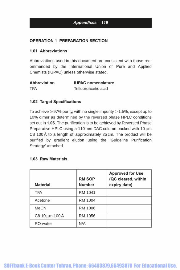
Appendices 119
Approved for Use RM SOP (QC cleared, within
Material Number expiry date)
TFA RM 1041
Acetone RM 1004
MeCN RM 1006
C8 10 �m 100 Å RM 1056
RO water N/A
OPERATION 1 PREPARATION SECTION
1.01 Abbreviations
Abbreviations used in this document are consistent with those rec-ommended by the International Union of Pure and AppliedChemists (IUPAC) unless otherwise stated.
Abbreviation IUPAC nomenclatureTFA Trifluoroacetic acid
1.02 Target Specifications
To achieve �97% purity, with no single impurity �1.5%, except up to10% dimer as determined by the reversed phase HPLC conditionsset out in 1.06. The purification is to be achieved by Reversed PhasePreparative HPLC using a 110 mm DAC column packed with 10 �mC8 100 Å to a length of approximately 25 cm. The product will bepurified by gradient elution using the ‘Guideline PurificationStrategy’ attached.
1.03 Raw Materials
1856174662_Appendices.qxd 1/18/06 4:04 PM Page 119
SOFTbank E-Book Center Tehran, Phone: 66403879,66493070 For Educational Use.

This page intentionally left blank
SOFTbank E-Book Center Tehran, Phone: 66403879,66493070 For Educational Use.

1.04 Equipment
Appendices 121
ES SOP Initials and Serial
Item Number Date Number
2 � Rainin SD-1 Pumps, fitted ES0516
with 800 cm3 pump heads**
Rainin UV-1 UV/Vis Detector** ES0518
Dynamax PC Chromatography ES0429
Data System
Prochrom 110 mm column** ES0385
Duran bottles 20 dm3
Waters 600 Pump ES0342
Waters 481 Detector ES0343
Waters 740 Integrator ES0344
Waters 712 Wisp ES0345
Millipore glass filter holder (1 dm3) ES0425
Glass microfibre filter unit* N/A
Top Pan Balance ES0300 To be
recorded
when used
Conical Flask*
Measuring Cylinders**
Gilson Precision Pipette,
50–200 mm3 ES0030
The equipment SOPs should be read prior to starting this stage of the process.
*Note these items shall be dedicated to this product.
**Note these items shall be dedicated to purification, labelled as such and stored
when not in use. Cleaning Verification shall be performed between projects for all
product contact surfaces as appropriate.
Serial numbers shall be added to the above table when the item is used. For critical
items the serial numbers shall be recorded on the process record where indicated at
the point of use.
1856174662_Appendices.qxd 1/18/06 4:04 PM Page 121
SOFTbank E-Book Center Tehran, Phone: 66403879,66493070 For Educational Use.

This page intentionally left blank
SOFTbank E-Book Center Tehran, Phone: 66403879,66493070 For Educational Use.

1.05 Consumables
Appendices 123
Item RM SOP Number
HPLC vials
0.5 dm3 Duran bottles
Pasteur pipettes
Whatman glass microfibre filters
Analytical column
1.06 In-Process Tests
The progress of the purification will be monitored by analytical HPLC. See
the analytical HPLC gradient for details. This method will have been devel-
oped in the Development Group and refined in the QC department
Analytical HPLC Conditions
Column: C18 Sample: Fractions
250 � 4.6 mm
Buffer A: 0.1% TFA in water Buffer B: 60% MeCN
in Buffer A
Flow rate: 1.0 cm3 �min�1 � � 210 nm
Temperature Ambient
Gradient: 0–100% B over
40 minutes
Analytical HPLC Strength Method
Various purification fractions or fraction pools may be analysed for strength
by peak area on HPLC. The analytical HPLC conditions shown above will be
used. A standard sample with a known product content will be supplied by
the Development Group. The peak area on HPLC of a solution of the stan-
dard (1.0 mg/cm3, net) will be compared with the percentage area of the
sample under test to estimate the quantity of the net product present.
1856174662_Appendices.qxd 1/18/06 4:04 PM Page 123
SOFTbank E-Book Center Tehran, Phone: 66403879,66493070 For Educational Use.

This page intentionally left blank
SOFTbank E-Book Center Tehran, Phone: 66403879,66493070 For Educational Use.

1.07 Ancillary SOPs
Appendices 125
SOP Initials and
SOP Title Number Date
Preparation and use of the QC0217
HPLC Column Standard
Preparation of Buffers SP0511
containing TFA (0.1% v/v)
for Analytical HPLC
Preparation of MeCN in SP0742
Water (1:1 v/v)
Column cleaning gradients SP0650
Assembly and packing of SP0514
the Prochrom column
Recovery of Product from SP0506
Large Scale Purification
1856174662_Appendices.qxd 1/18/06 4:04 PM Page 125
SOFTbank E-Book Center Tehran, Phone: 66403879,66493070 For Educational Use.

This page intentionally left blank
SOFTbank E-Book Center Tehran, Phone: 66403879,66493070 For Educational Use.

Appendices 127
1.08 Cleaning
All glassware used in the purification shall be project
dedicated and appropriately labelled for the project. New
glassware will be rinsed with MilliQ H2O prior to a final
wash with acetone before use. All glassware that is
repeatedly used will be cleaned using the guidelines set
out in the Cleaning of Laboratory Glassware SOP
(SPO523) and this shall be recorded prior to the com-
mencement of each operation. Where applicable Cleaning
Verification Reports must be cross referenced.
1856174662_Appendices.qxd 1/18/06 4:04 PM Page 127
SOFTbank E-Book Center Tehran, Phone: 66403879,66493070 For Educational Use.

This page intentionally left blank
SOFTbank E-Book Center Tehran, Phone: 66403879,66493070 For Educational Use.
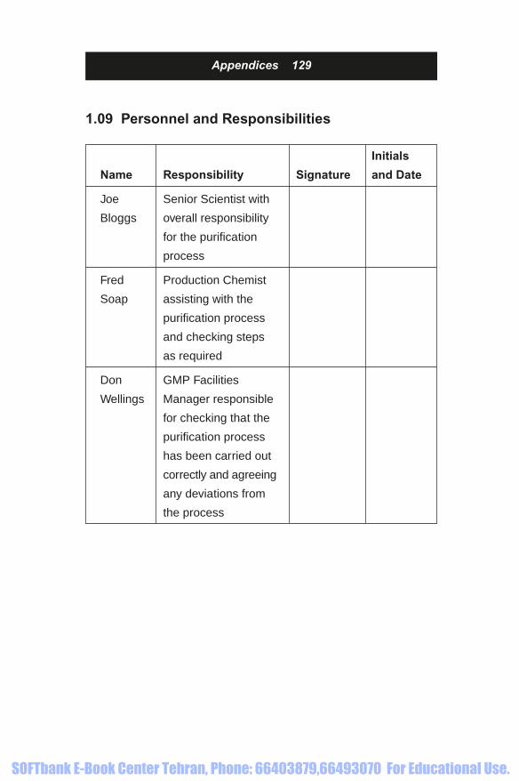
1.09 Personnel and Responsibilities
Appendices 129
Initials
Name Responsibility Signature and Date
Joe Senior Scientist with
Bloggs overall responsibility
for the purification
process
Fred Production Chemist
Soap assisting with the
purification process
and checking steps
as required
Don GMP Facilities
Wellings Manager responsible
for checking that the
purification process
has been carried out
correctly and agreeing
any deviations from
the process
1856174662_Appendices.qxd 1/18/06 4:04 PM Page 129
SOFTbank E-Book Center Tehran, Phone: 66403879,66493070 For Educational Use.

This page intentionally left blank
SOFTbank E-Book Center Tehran, Phone: 66403879,66493070 For Educational Use.

Appendices 131
1.10 Safety
The following COSHH, Hazardous Experimental Assessments and
Material Safety Data Sheets (MSDS) should be read before starting
this process. Sign and date the table below after reading the assess-
ments and MSDSs.
HAZARDOUS REFERENCE Initials
ASSESSMENT CODE and Date
Solvent Preparation COSHHA008
for Preparative
Chromatography
Sample Recovery COSHHA009
from Preparative
Chromatography
Lyophilization of COSHHA010
Peptides
Packing a Preparative COSHHA011
Chromatography
Column
Sample Preparation COSHHA016
for Preparative
Chromatography
Preparative HPLC COSHHA01
1856174662_Appendices.qxd 1/18/06 4:04 PM Page 131
SOFTbank E-Book Center Tehran, Phone: 66403879,66493070 For Educational Use.

132 Appendices
Safety Precautions
Safety glasses and coverall suits/lab coats must be worn at all times
by personnel in the laboratory.
Whilst handling all chemicals, gloves must be worn.
When TFA is handled gauntlets or arm/sleeve protectors will
be used.
REFERENCE Initials
COSHH ASSESSMENT CODE and Date
Preparation of Samples COSHH024
for Purifications
Loading of Samples for COSHHA026
Purification
Fraction Collection COSHHA027
Preparation of Samples COSHHA029
for HPLC Analysis
Analytical HPLC COSHHA032
Pooling of HPLC Fractions COSHHA033
Washing Glassware COSHHA037
using Acetone
Use of 70% propan-2-ol COSHHA074
for Cleaning Laboratories
Disposal of Chemicals COSHHA076
Transport of Chemicals COSHHA077
1856174662_Appendices.qxd 1/18/06 4:04 PM Page 132
SOFTbank E-Book Center Tehran, Phone: 66403879,66493070 For Educational Use.

All procedures should be carried out within a fume cupboard, apart
from weighing which can be undertaken in a ventilated cabinet. Prior
to using the ventilated cabinet the operator should check that the
LEV is working.
Ensure that the fume cupboard is as tidy as possible, that the extrac-
tion is working efficiently and that only one ‘port’ of the fume cupboard
is open at any one time (an alarm will go off if the face velocity drops
below the minimum safe operating level) or the fume cupboard sash is
at its lowest practical level when using the older fume cupboards.
When the operator is absent all the ‘ports’/the sash should be closed.
Check that the fume cupboards are adequately bonded.
Check that any electrical appliance to be used has been passed by
an electrician. If it has been passed by the electrician and appears
to be faulty get it rechecked before use.
Any spillage should be dealt with quickly and with reference to the
substances COSHH assessment or MSDS. BA equipment may be
required. Other working areas may need informing as the laboratory
is at positive pressure to all surrounding areas.
If whilst handling the chemicals involved in these processes, contact
is made with your skin, eyes, by inhalation or by ingestion, seek
medical help initially from a First Aider. Refer to the MSDS
All glassware should be checked for cracks and chips prior to use.
All accidents and spillages should be reported to your supervisor
and safety officer.
The Project ‘HazOp’ Study should be referred to for assessment of
the risks associated with this project.
Appendices 133
1856174662_Appendices.qxd 1/18/06 4:04 PM Page 133
SOFTbank E-Book Center Tehran, Phone: 66403879,66493070 For Educational Use.

This page intentionally left blank
SOFTbank E-Book Center Tehran, Phone: 66403879,66493070 For Educational Use.

Appendices 135
OPERATION 2 PRE-PURIFICATION COLUMN
PREPARATION
For all steps record any observations and minor
deviations on the blank section alongside the
process prompts. This applies for all the subsequent
Operations.
Manufacturing Facility __________ Date __________
2.01 Confirm that the DAC Column is packed with C8
(2.0 kg of 10 �m, 100 Å pore size) to achieve a minimum
25 cm column length. Record the following:
GI number of C8 __________
Packing operation number __________
Operator __________
Date __________
2.02 Prepare a solution of Buffer A (0.1% v/vTFA in
H2O) and Buffer B (0.1% v/vTFA in MeCN) for use in
purification. Record the following:
Batch number of Buffer A __________
Batch number of Buffer B __________
Operator __________
Date __________
1856174662_Appendices.qxd 1/18/06 4:04 PM Page 135
SOFTbank E-Book Center Tehran, Phone: 66403879,66493070 For Educational Use.

This page intentionally left blank
SOFTbank E-Book Center Tehran, Phone: 66403879,66493070 For Educational Use.

OPERATION 3 PURIFICATION P_____
Manufacturing Facility __________ Date __________
For all steps record any observations and minor
deviations on the blank section alongside the
process prompts. This applies for all the subsequent
Operations.
3.01 Prior to this operation clean glassware to be
cleaned as indicated in SOP SPO523. Indicate that
cleaning is completed as appropriate:
4 dm3 conical flask __________
250 cm3 measuring cylinder __________
1 dm3 measuring cylinder __________
Magnetic follower __________
Glass microfibre filter unit __________
5 dm3 filter flask __________
Membrane filter holder __________
Operator __________
Date __________
Appendices 137
1856174662_Appendices.qxd 1/18/06 4:04 PM Page 137
SOFTbank E-Book Center Tehran, Phone: 66403879,66493070 For Educational Use.
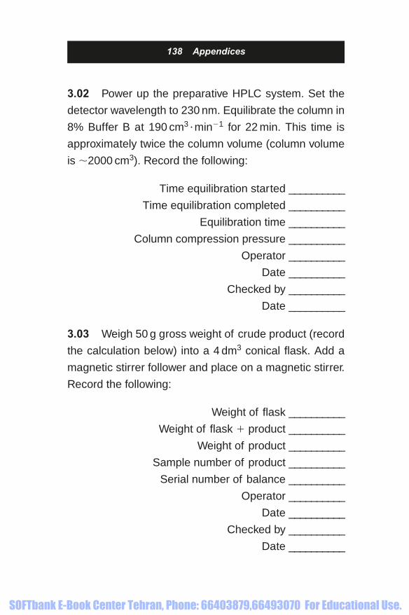
138 Appendices
3.02 Power up the preparative HPLC system. Set the
detector wavelength to 230 nm. Equilibrate the column in
8% Buffer B at 190 cm3 �min�1 for 22 min. This time is
approximately twice the column volume (column volume
is �2000 cm3). Record the following:
Time equilibration started __________
Time equilibration completed __________
Equilibration time __________
Column compression pressure __________
Operator __________
Date __________
Checked by __________
Date __________
3.03 Weigh 50 g gross weight of crude product (record
the calculation below) into a 4 dm3 conical flask. Add a
magnetic stirrer follower and place on a magnetic stirrer.
Record the following:
Weight of flask __________
Weight of flask product __________
Weight of product __________
Sample number of product __________
Serial number of balance __________
Operator __________
Date __________
Checked by __________
Date __________
1856174662_Appendices.qxd 1/18/06 4:04 PM Page 138
SOFTbank E-Book Center Tehran, Phone: 66403879,66493070 For Educational Use.

3.04 Add 250 cm3 of Buffer B to the crude product and
start stirring. Record the following:
Batch number of Buffer B __________
Volume of Buffer B __________
Operator __________
Date __________
3.05 Add 2.25 dm3 of Buffer A slowly over 10 minutes
and stir until all the solid has dissolved, approximately 30
minutes. Record the following:
Time stirring started __________
Time stirring complete __________
Elapsed time for stirring __________
Batch number of Buffer A __________
Volume of Buffer A __________
Operator __________
Date __________
Appendices 139
1856174662_Appendices.qxd 1/18/06 4:04 PM Page 139
SOFTbank E-Book Center Tehran, Phone: 66403879,66493070 For Educational Use.

140 Appendices
3.06 Filter the crude product solution through a GF/D
glass microfibre filter into a 4 dm3 filter flask. Rinse the
4 dm3 conical flask with 3 � 50 cm3 of Buffer B in Buffer
A (8% v/v) and transfer to the filter. Record the following:
GI number of filter membrane ________
Volume of Buffer B in Buffer A (8% v/v) ________
Batch number of Buffer B in Buffer A (8% v/v) ________
Number of rinses ________
Volume of rinses ________
Operator ________
Date ________
3.07 Filter the crude product solution through a GF/B filter
into a 4 dm3 filter flask. Rinse the 4 dm3 conical flask from
step 3.06 with 3 � 50 cm3 of Buffer B in Buffer A (8% v/v)
and transfer to the filter. Remove a sample for analytical
HPLC refer to 1.06, label the sample 14449/0048/3.07(s),
attach the trace to this process record. Record the following:
GI number of filter membrane ________
Volume of Buffer B in Buffer A (8% v/v) ________
Batch number of Buffer B in Buffer A (8% v/v) ________
Number of rinses ________
Volume of rinses ________
Operator ________
Date ________
1856174662_Appendices.qxd 1/18/06 4:04 PM Page 140
SOFTbank E-Book Center Tehran, Phone: 66403879,66493070 For Educational Use.

3.08 Restart the flow on the HPLC in the equilibration
conditions. Zero the UV/Vis detector. Load the crude prod-
uct solution onto the column at 190 cm3 �min�1 through
Pump A. All eluent is to be collected. Record the following:
Time loading started ________
Time loading finished ________
Duration of loading ________
Detector zeroed (yes/no) ________
Operator ________
Date ________
3.09 After loading the crude product rinse out the flask
from step 3.07 and injection line with 100 cm3 of Buffer B
in Buffer A (8% v/v). Record the following:
Volume of Buffer B in Buffer A (8% v/v) ________
Batch number of Buffer B in Buffer A (8% v/v) ________
Operator ________
Date ________
3.10 Run the column with 8% B at 190 cm3 �min�1 for
5 minutes. Record the following:
Time solvent flow restarted ________
Time re-equilibration completed ________
Duration of re-equilibration ________
Operator ________
Date ________
Appendices 141
1856174662_Appendices.qxd 1/18/06 4:04 PM Page 141
SOFTbank E-Book Center Tehran, Phone: 66403879,66493070 For Educational Use.

142 Appendices
3.11 Start the purification gradient. Start collecting
1 minute fractions manually when a significant UV
response occurs. Continue collecting until the product
has eluted. Record the time the gradient and fraction col-
lection started. Label the fractions PX/FY-Z where Y and
Z are sequential fraction numbers, X is the sequential
purification number.
Time gradient started __________
Time fraction collection started __________
Duration of fraction collection __________
Number of fractions collected __________
Operator __________
Date __________
3.12 After the gradient has finished, remove samples
for HPLC analysis (see 3.13). Cap the bottles and store
fractions at 2–8°C (in laboratory fridge).
Time gradient finished __________
Duration of gradient __________
Storage location __________
Operator __________
Date __________
1856174662_Appendices.qxd 1/18/06 4:04 PM Page 142
SOFTbank E-Book Center Tehran, Phone: 66403879,66493070 For Educational Use.

3.13 Record which fractions are to be analysed. Analyse
these fractions by HPLC using the analytical HPLC condi-
tions in Step 1.06. Attach all HPLC traces to this record.
List fractions to be analysed below.
Note: Dilute fractions X10 before analysis
Operator __________
Date __________
3.14 Prepare a trial pool in a snap cap vial consisting of
50 mm3 of each fraction that meets the required specifica-
tion by HPLC. Label the pool PX/FY-Z, where X is the
purification number, Y and Z covers the fraction range in
the pool. Dilute pool 10 times and carry out a HPLC of this
pool to confirm that the pool meets the required specifica-
tion. Record the following:
Sample number of pool __________
Does the pool meet specification (yes/no) __________
Operator __________
Date __________
Appendices 143
1856174662_Appendices.qxd 1/18/06 4:04 PM Page 143
SOFTbank E-Book Center Tehran, Phone: 66403879,66493070 For Educational Use.

3.15 If the trial pool does not meet the specification the
Senior Chemist will use his/her judgement to assess a
second trial pool. Record the details of further pools on a
purification deviation sheet and attach to this process
instruction.
Additional pools required (yes/no) __________
Operator __________
Date __________
144 Appendices
1856174662_Appendices.qxd 1/18/06 4:04 PM Page 144
SOFTbank E-Book Center Tehran, Phone: 66403879,66493070 For Educational Use.

PURIFICATION DEVIATION SHEET
This sheet shall be used to summarize additional trial
pools of purification fractions for Step 3.15.
Prepare a trial pool in a snap cap vial consisting of
50 mm3 of each fraction that meets the required specifi-
cation by HPLC. Label the pool PX/FY-Z, where X is the
purification number and Y to Z covers the fraction range
in the pool. Dilute the pool 10 times and carry out a
HPLC of this pool to confirm that the pool meets the
required specification. Attach the HPLC traces to this
process instruction. Record the following:
Sample number of pool __________
Pool meets specification (yes/no) __________
HPLC of pool attached (yes/no) __________
Operator __________
Date __________
Appendices 145
1856174662_Appendices.qxd 1/18/06 4:04 PM Page 145
SOFTbank E-Book Center Tehran, Phone: 66403879,66493070 For Educational Use.

Prepare a trial pool in a snap cap vial consisting of 50 mm3
of each fraction that meets the required specification by
HPLC. Label the pool PX/FY-Z. Dilute pool 10 times and
carry out a HPLC of this pool to confirm that the pool
meets the required specification. Attach the HPLC traces
to this process instruction. Record the following:
Sample number of pool __________
Pool meets specification (yes/no) __________
HPLC of pool attached (yes/no) __________
Operator __________
Date __________
146 Appendices
1856174662_Appendices.qxd 1/18/06 4:04 PM Page 146
SOFTbank E-Book Center Tehran, Phone: 66403879,66493070 For Educational Use.

3.16 Determine the quantity of product in the trial pool
using the following equation.
10 � Area of pooled fraction� 1.0 mg �cm�3
Area of strength standard
� concentration of product in pool/mg �cm�3
Reference Number of 1.0 mg �cm�3 standard __________
Area of pool __________
Area of standard __________
Concentration of product in pool (mg �cm�3) __________
Volume of pool __________
Quantity of product (mg) __________
Operator __________
Date __________
Checked by __________
Date __________
Concentration
of product
(mg cm 3� � )
⎡
⎣
⎢⎢⎢⎢⎢
⎤
⎦
⎥⎥⎥⎥⎥⎥
⎡
⎣
⎢⎢⎢⎢⎢
⎤
⎦
⎥⎥⎥⎥⎥
� ��
volume
of pool
(cm
qu
3 )
aantity of
product/mg
⎡
⎣⎢⎢
⎤
⎦⎥⎥
Appendices 147
1856174662_Appendices.qxd 1/18/06 4:04 PM Page 147
SOFTbank E-Book Center Tehran, Phone: 66403879,66493070 For Educational Use.

148 Appendices
3.17 Record the fate of all fractions on the process
record for Reconciliation of Fractions.
3.18 Store all fractions in the fridge until required for
final freeze drying. Record the following:
Identity of fridge __________
Operator __________
Date __________
3.19 At the end of each day wash the purification system
including the solvent lines, injection line, pumps, flow cell
and column with MeCN/H2O (5 dm3,1:1 v/v) at 200 cm3/min.
Volume of MeCN/H2O __________
Batch number of MeCN/H2O __________
Operator __________
Date __________
APPROVAL OF STAGE
GMP Facilities Manager Date:
Quality Assurance Date:
1856174662_Appendices.qxd 1/18/06 4:04 PM Page 148
SOFTbank E-Book Center Tehran, Phone: 66403879,66493070 For Educational Use.
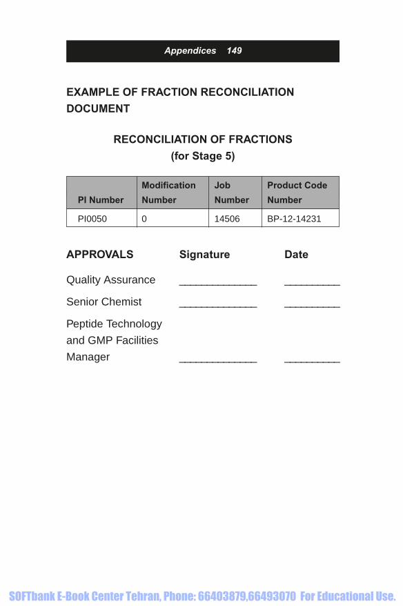
EXAMPLE OF FRACTION RECONCILIATION
DOCUMENT
RECONCILIATION OF FRACTIONS
(for Stage 5)
Appendices 149
Modification Job Product Code
PI Number Number Number Number
PI0050 0 14506 BP-12-14231
APPROVALS Signature Date
Quality Assurance ______________ __________
Senior Chemist ______________ __________
Peptide Technology
and GMP Facilities
Manager ______________ __________
1856174662_Appendices.qxd 1/18/06 4:04 PM Page 149
SOFTbank E-Book Center Tehran, Phone: 66403879,66493070 For Educational Use.

This page intentionally left blank
SOFTbank E-Book Center Tehran, Phone: 66403879,66493070 For Educational Use.

OPERATION 1 SUMMARY
1.01 This process instruction is used to summarize the
fate of fractions from up to four purifications carried out
according to PI0043 (prior to the desalt process).
The fate of fractions that are not combined for desalt will
also be retrospectively recorded on this process instruction.
Record the fate of all fractions on the reconciliation
tables (Tables A1 to A3).
Date when all fraction reconciliation is complete ______
Operator _______
Senior Chemist _______
1.02 Record any additional notes on fraction reconcili-
ation below.
Appendices 151
Operator __________
Date __________
1856174662_Appendices.qxd 1/18/06 4:04 PM Page 151
SOFTbank E-Book Center Tehran, Phone: 66403879,66493070 For Educational Use.

This page intentionally left blank
SOFTbank E-Book Center Tehran, Phone: 66403879,66493070 For Educational Use.

1.03 PURIFICATION NUMBER _____
Record any additional notes on table (e.g. net product
from trial pool or actual pool)
Table A1
Appendices 153
Fraction or Fate of
Starting fractions Total Net product pool or Initials
Material pooled volume/dm3 content/g fractions and date
1856174662_Appendices.qxd 1/18/06 4:04 PM Page 153
SOFTbank E-Book Center Tehran, Phone: 66403879,66493070 For Educational Use.

This page intentionally left blank
SOFTbank E-Book Center Tehran, Phone: 66403879,66493070 For Educational Use.

1.04 PURIFICATION NUMBER _____
Record any additional notes on table (e.g. net product
from trial pool or actual pool)
Table A2
Appendices 155
Fraction or Fate of
Starting fractions Total Net product pool or Initials
Material pooled volume/dm3 content/g fractions and date
1856174662_Appendices.qxd 1/18/06 4:04 PM Page 155
SOFTbank E-Book Center Tehran, Phone: 66403879,66493070 For Educational Use.

This page intentionally left blank
SOFTbank E-Book Center Tehran, Phone: 66403879,66493070 For Educational Use.

1.05 PURIFICATION NUMBER _____
Record any additional notes on table (e.g. net product
from trial pool or actual pool)
Table A3
Appendices 157
Fraction or Fate of
Starting fractions Total Net product pool or Initials
Material pooled volume/dm3 content/g fractions and date
1856174662_Appendices.qxd 1/18/06 4:04 PM Page 157
SOFTbank E-Book Center Tehran, Phone: 66403879,66493070 For Educational Use.

This page intentionally left blank
SOFTbank E-Book Center Tehran, Phone: 66403879,66493070 For Educational Use.

References
1856174662_References.qxd 1/18/06 4:05 PM Page 159
SOFTbank E-Book Center Tehran, Phone: 66403879,66493070 For Educational Use.

This page intentionally left blank
SOFTbank E-Book Center Tehran, Phone: 66403879,66493070 For Educational Use.

[1.1] Tswett, M.S. Botanisches Centralblatt. 89, 120–123
(1902).
[1.2] Couillard, F. Chromatography Apparatus, US Patent
4,597,866, 1986-07-01.
[1.3] Petro, M. and Nguyen, S.H. Liquid Chromatography
Column Distributor. US Patent Application
US20020099452, 3003-09-18.
[1.4] Colvin jr, A.E. and Hanley, M.W. Fluid Control
Device. US Patent 4,894,152, 1990-01-16.
[1.5] McNeil, R. Fluid Flow Control Device. US Patent
4,354,932, 1982-10-19.
[1.6] Bayer Technologies.
[1.7] LePlang, M. and Chabrol, D. Fluid Distributor and
Device for Treating a Fluid such as a Chromatograph
Equipped with said Distributor. US Patent
5,141,635, 1992-08-05.
[1.8] Heuer, C., Hugo, P., Mann, G., and Seidel-
Morgenstern, A. Journal of Chromatography. A,
(1996) 19–29.
CHAPTER 1
References
1856174662_References.qxd 1/18/06 4:05 PM Page 161
SOFTbank E-Book Center Tehran, Phone: 66403879,66493070 For Educational Use.

[1.9] Dapremont, O., Cox, G.B., Martin, M., Hilaireau, P.
and Colin, H. Journal of Chromatography. A, (1998)
81–99.
[1.10] Cox, G.B. Journal of Chromatography. A, 599 (1992)
195–203.
[1.11] Nicoud, R-M. and Charton, F. Journal of
Chromatography. A, 702 (1995) 97–112.
[1.12] Broughton, D.B. and Gerholg, C.G. US Patent (1961)
2,985-589.
[1.13] Barker, P.E. Chem. Eng. Sci. (1960) 13, 82.
[1.14] Guest, D.W. Journal of Chromatography. A, 760
(1997) 159–163.
[1.15] Nicoud, R-M. Separation Science and Technology,
(2000) 2, 476–509.
[1.16] Gottsclich, N. and Kasche, V. Journal of
Chromatography. A, (1997) 201–206.
[1.17] Abel, S., Bäbler, M., Arpagaus, C., Mazzotti, M. and
Stadler, J. Journal of Chromatography. A, (2004)
201–210.
162 References
1856174662_References.qxd 1/18/06 4:05 PM Page 162
SOFTbank E-Book Center Tehran, Phone: 66403879,66493070 For Educational Use.

[2.1] Snyder, R.L., Glajch, J.L. and Kirkland, J.J. Practical
HPLC Method Development. John Wiley & Sons Inc.
1988. ISBN 0-471-62782-8.
[2.2] Brown, P.R. and Hartwick, R.A. High Performance
Liquid Chromatography. John Wiley & Sons Inc.
1989. ISBN 0-471-84506-X.
[2.3] Martin, A.J.P. and Synge, R.L.M. Biochem. J. (1941)
35, 91.
[2.4] van Deemter, J.J., Zuiderweg, F.J. and Klinkenberg, A.
Chem. Eng. Sci., (1956) 5, 271–289.
[3.1] Tswett, M.S. Botanisches Centralblatt (1902) 89,
120–123.
[3.2] Wellings, D.A. Stepwise Elaboration of Quasi-
Homogeneous Peptide-Gel Networks. PhD thesis
submitted to the Council for National Academic
Awards (1986).
CHAPTER 3
CHAPTER 2
References 163
1856174662_References.qxd 1/18/06 4:05 PM Page 163
SOFTbank E-Book Center Tehran, Phone: 66403879,66493070 For Educational Use.

164 References
[3.3] Pirkle, W.H. and Anderson, R.W. J. Org. Chem.
(1974) 3901–3903.
[3.4] Dalgliesh, C.E. J. Chem. Soc. (1952) 47, 3940–3942.
[3.5] Pirkle, W.H. and House, D.W. J. Org. Chem. (1979)
44, No.12, p1957.
[3.6] Allenmark, S.G. and Andersson, S. J. Chromatography
A. (1994) 666, 167–179.
[3.7] Hermansson, J., Hermansson, I. and Nordin, J.
J. Chromatography A. (1993) 631, 79–90.
[3.8] Bressolle, F., Audran, M., Pham, T.N. and Vallon, J.J.
J. Chromatography B Biomedical Applications.
(1996) 687, 303–336.
[3.9] Han, S.M. Biomedical Chromatography. 11, 259–271.
[3.10] Armstrong, D.W., Bagwill, C., Chen, S., Chen, J.R.,
Tang, Y. and Zhou, Y. Analytical Chemistry. (1994)
66, 1473–1484.
[3.11] Shibukawa, A. and Nakagawa, T. Chiral Separations
by HPLC. Krstulovic, A.M., Ellis Horwood Ltd:
New York (1989).
[3.12] Moller, P., Sanchez, D., Allenmark, S. and Andersson, S.
Chiral Adsorbents and Preparation thereof as well as
1856174662_References.qxd 1/18/06 4:05 PM Page 164
SOFTbank E-Book Center Tehran, Phone: 66403879,66493070 For Educational Use.

Compounds on which the Adsorbents are Based and
Preparation of these Compounds. Patent SE
9203646, 1993-04-24.
[3.13] Y. Okamato, Chem. Lett. (1986) 1237.
[3.14] Levin, S. and Abu-Lafi, S. “The Role of
Enantioselective Liquid Chromatographic Separations
Using Chiral Stationary Phases in Pharmaceutical
Analysis”, in Advances in Chromatography.
E. Grushka and P. R. Brown, Eds., Marcel Dekker
Inc.: NY, (1993) 33, 233–266.
[3.15] Nicoud, R-M. Separation Science and Technology,
(2000) 2, 476–509.
[3.16] Lowe, C.R. and Dean, P.D.G. Affinity
Chromatography. John Wiley & Sons Inc. 1989.
[4.1] Couillard, F. Chromatography Apparatus, US Patent
4,597,866, 1986-07-01.
[4.2] Rausch, C.W., Tuvin, Y. and Neue, U.D. Improvements
in chromatography, Patent GB2110951, 1983-06-29.
CHAPTER 4
References 165
1856174662_References.qxd 1/18/06 4:05 PM Page 165
SOFTbank E-Book Center Tehran, Phone: 66403879,66493070 For Educational Use.

166 References
[4.3] Ritacco, R.P. and Hampton, T.W. HPLC column and
column packing method, Patent DK46188, 1988-01-29.
[5.1] Wellings, D.A. Preparative HPLC of Peptides. IBC
Symposium on Industrial Scale Peptide Synthesis,
Las Vegas, March 1997.
[5.2] van Deemter, J.J., Zuiderweg, F.J. and Klinkenberg, A.
Chem. Eng. Sci., (1956) 5, 271–289.
[6.1] Rules and Guidance for Pharmaceutical Manufacturers
and Distributors (known as the Orange Guide),
Medicines and Healthcare Products Regulatory Agency,
published by the Stationery Office, 2002.
CHAPTER 6
CHAPTER 5
1856174662_References.qxd 1/18/06 4:05 PM Page 166
SOFTbank E-Book Center Tehran, Phone: 66403879,66493070 For Educational Use.

Index
1856174662_Index.qxd 1/18/06 8:38 AM Page 167
SOFTbank E-Book Center Tehran, Phone: 66403879,66493070 For Educational Use.

This page intentionally left blank
SOFTbank E-Book Center Tehran, Phone: 66403879,66493070 For Educational Use.

A
Acetonitrile 38
Achirality 42
Active pharmaceutical ingredients (APIs) 105
Affinity chromatography 54–56
Analytical HPLC 83, 90–91
strength method 123
Annular expansion 59–61
B
Band broadening 24, 27
Binary mixture separation 12–13, 96
Boxcar injections 79
for chiral separations 95–99
Index
Note: Italicized page numbers denote entries from tables or
figures.
1856174662_Index.qxd 1/18/06 8:38 AM Page 169
SOFTbank E-Book Center Tehran, Phone: 66403879,66493070 For Educational Use.

C
Calibration standards 105
Capacity factor 22
cGMP 10, 103
see also Equipment qualification
cGMP processes 71
Chiral chromatography 45, 56, 79
Chiral molecules 11–12, 42
Chiral purity 42
Chiral separations
boxcar injections 95–99
chirality 42–43
enantiomers, separation 44–47
importance 41–42
optical purity 43–44
Chirality 42–43
Chromatogram
measurements 21–22
Chromatographic separation, modes 29
affinity chromatography 54–56
chiral separations 41–47
exclusion chromatography 53–54
ion exchange chromatography 47–52
normal phase chromatography 35–37
reversed phase chromatography 37–41
170 Index
1856174662_Index.qxd 1/18/06 8:38 AM Page 170
SOFTbank E-Book Center Tehran, Phone: 66403879,66493070 For Educational Use.

Chromatography 3–5, 11
affinity 54–56
column 12
exclusion 53–54
ion exchange 47–52
modes 31
normal phase 31, 35–37
reversed phase 10, 37–41
size exclusion 37, 53–54
SMB 4, 12–14
Column loading 82–83, 84
Column packing 53–54, 59–66
Column preparation
pre-purification 135
purification 137–144
Column wall effect 26–28
Conductivity meter 50
Crude mixture, potential quantity
in comparison to column diameter 67
Current Good Manufacturing Practice see cGMP
D
DAC 5, 8, 9
columns, packing methodology 61–63
Index 171
1856174662_Index.qxd 1/18/06 8:38 AM Page 171
SOFTbank E-Book Center Tehran, Phone: 66403879,66493070 For Educational Use.

Design qualification (DQ) 104
Deviation sheet 117
Diastereoisomeric excess (de) 43
Diastereoisomers 43
Distillation 3
Distribution plates 6–7
Divinylbenzene
macroporous copolymers 10
Documentation and record keeping 101–109
Dynamic axial compression see DAC
E
Effective plate height 93–94
Enantiomeric excess (ee) 43
Enantiomers 42
separation of 44–47
End-capping 39
Epimers 43
Equipment qualification
design qualification (DQ) 104
factory acceptance tests (FATs) 104
installation qualification (IQ) 104
operational qualification (OQ) 105
performance qualification (PQ) 105
172 Index
1856174662_Index.qxd 1/18/06 8:38 AM Page 172
SOFTbank E-Book Center Tehran, Phone: 66403879,66493070 For Educational Use.

site acceptance tests (SATs) 104
user requirement specification (URS) 103–104
Exclusion chromatography
column packing media 53–54
gel filtration 53
gel permeation 54
see also Size exclusion chromatography
F
Factory acceptance tests (FATs) 104
Federal Drug Agency (FDA) 103
Flow and sample distribution engineering 6
Flow rate optimization 24–25, 87, 88, 93–95
Fluid dynamics 19–28
Fraction reconciliation
fate of 149
Friction 19–28
tackling method 88
Full-time equivalents (FTEs) 11
G
Gel filtration 52, 53
Gel permeation 53, 54
Index 173
1856174662_Index.qxd 1/18/06 8:38 AM Page 173
SOFTbank E-Book Center Tehran, Phone: 66403879,66493070 For Educational Use.

Gradient elution 37, 38, 80, 82
Gradient selection
preparative separation 91–92
H
Height equivalent to a theoretical plate (HETP) 22, 23–25
HPLC
chiral 12, 44
normal phase 43
preparative 14, 35, 38, 67, 69, 73
reversed phase 38, 40, 43
Human insulin 26
I
In-process tests 108, 123
Installation qualification (IQ) 104
International Union for Pure and Applied Chemists (IUPAC)
37, 107
Compendium of Chemical Technology 35
174 Index
1856174662_Index.qxd 1/18/06 8:38 AM Page 174
SOFTbank E-Book Center Tehran, Phone: 66403879,66493070 For Educational Use.

Ion exchange chromatography
anion exchange stationary phase 48, 48–50
cation exchange stationary phase 48
drawbacks 52
oligonucleotides 50–52
usage 47
Isocratic elution 37, 82, 96, 99
L
Loading study 92–93
Lyophilization 71
M
Macroporous polymerics 10–11
Mass transport 19–28
Material safety data sheets (MSDSs) 109
Mobile phase 19, 20, 54
Index 175
1856174662_Index.qxd 1/18/06 8:38 AM Page 175
SOFTbank E-Book Center Tehran, Phone: 66403879,66493070 For Educational Use.

N
Normal phase 35
Normal phase chromatography 35–37
meaning 31
use 35, 37
Number of theoretical plates 20
O
Oligonucleotide 50–52
basic structure 51
Operational qualification (OQ) 105
Optical purity 42, 43–44
Optimum load determination
for self-displacement of impurities 92–93
Overload chromatography see Sample self-displacement
P
Particle size
in chromatographic separation 32
176 Index
1856174662_Index.qxd 1/18/06 8:38 AM Page 176
SOFTbank E-Book Center Tehran, Phone: 66403879,66493070 For Educational Use.
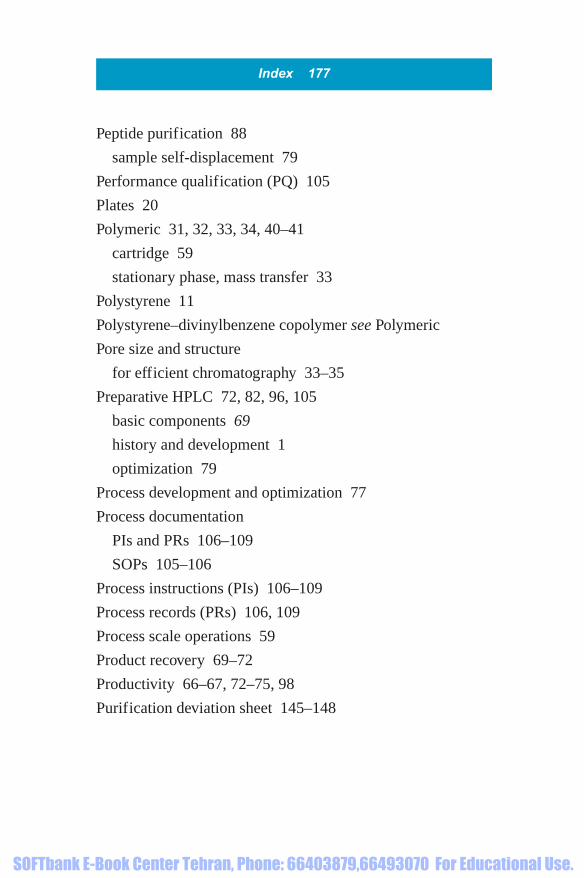
Peptide purification 88
sample self-displacement 79
Performance qualification (PQ) 105
Plates 20
Polymeric 31, 32, 33, 34, 40–41
cartridge 59
stationary phase, mass transfer 33
Polystyrene 11
Polystyrene–divinylbenzene copolymer see Polymeric
Pore size and structure
for efficient chromatography 33–35
Preparative HPLC 72, 82, 96, 105
basic components 69
history and development 1
optimization 79
Process development and optimization 77
Process documentation
PIs and PRs 106–109
SOPs 105–106
Process instructions (PIs) 106–109
Process records (PRs) 106, 109
Process scale operations 59
Product recovery 69–72
Productivity 66–67, 72–75, 98
Purification deviation sheet 145–148
Index 177
1856174662_Index.qxd 1/18/06 8:38 AM Page 177
SOFTbank E-Book Center Tehran, Phone: 66403879,66493070 For Educational Use.

Q
Quality checks
on consumables 108
R
Racemic 42, 73
Radial compression 59–61
Reversed phase chromatography 37–41, 71, 72, 75
polymeric media 10, 89
Reversed phase media 39, 40–41, 80, 89
aqueous buffer 38
S
Safety precautions
in laboratory 132–133
Salmon calcitonin 26
Sample self-displacement
peptide purification 79
Scanning electron micrograph (SEM) 9, 36
178 Index
1856174662_Index.qxd 1/18/06 8:38 AM Page 178
SOFTbank E-Book Center Tehran, Phone: 66403879,66493070 For Educational Use.

Separation factor 22
Silica 31, 33, 35, 37, 39
Simulated moving bed see SMB
Sinter plate 7
Site acceptance tests (SATs) 104
Size exclusion chromatography 37, 53, 54, 79
see also Exclusion chromatography
Slurry and column preparation
in column packing protocol, column type 1 64–65
Slurry concentration
in column packing protocol, column type 1 63–64
SMB 4–5, 12, 13–15, 95
chromatography 12
Spray drying 72
Standard operating procedures (SOPs) 105–106, 108
Star type distribution plate 6–7
Stationary phase 19, 26, 34, 48, 55
Stereo-centre 43
Styrene
macroporous copolymers 10
Surface area
for efficient chromatography 34
Synthetic peptides, purification 80, 81
sample self-displacement 79
Index 179
1856174662_Index.qxd 1/18/06 8:38 AM Page 179
SOFTbank E-Book Center Tehran, Phone: 66403879,66493070 For Educational Use.
T
Three point rule 45–46
Trifluoroacetic acid 38
U
User requirement specification (URS) 103–104
V
van Deemter’s theory 33–34
equation 88
mass transfer 33
180 Index
1856174662_Index.qxd 1/18/06 8:38 AM Page 180
SOFTbank E-Book Center Tehran, Phone: 66403879,66493070 For Educational Use.