A Practical Guide to Relational Database Design · A Practical Guide to Relational Database Design...
48
A Practical Guide to Relational Database Design ONE CHAPTER SAMPLE .pdf
Transcript of A Practical Guide to Relational Database Design · A Practical Guide to Relational Database Design...

A Practical Guide to Relational Database Design
ONE CHAPTER SAMPLE .pdf

A Practical Guide to Relational Database Design
From Business Analysis Via Data Modelling To Physical Design ONE CHAPTER SAMPLE .pdf Peter Domanski & Philip Irvine Diaxon Ltd Leominster, Herefordshire, UK

Published by Diaxon Ltd. (formally Domanski-Irvine Book Company) , Coldwell Farm, Stretfordbury, Leominster, Herefordshire, HR6 0QL Email [email protected] Domanski, Peter Irvine, Philip Title: A Practical Guide to Relational Database Design (From Business Analysis, Via Data Modelling, To Physical Design) Second Edition ISBN 0 9526043 1 0 Copyright © 2000 Domanski-Irvine Book Company All rights reserved. No part of this publication may be reproduced, stored in a retrieval system, or transmitted, in any form or by any means, electronic, mechanical, photocopying, recording, or otherwise, without the prior permission of Diaxon Ltd (formally The Domanski-Irvine Book Company.) (2.2) Typeset, printed and bound by Domanski-Irvine Book Company, Coldwell Farm. Stretfordbury, Leominster.
NOTICE:
If this notice appears, this book has been reproduced from an Adobe .pdf file sourced from www.diaxon.com. Diaxon Ltd. is happy for sections of this document to be quoted with due acknowledgement to the authors. However, please respect the copyright laws. If you wish to reproduce parts of this document for anything other than personal use, permission should be sought from the publishers beforehand. Contact [email protected]

TABLE OF CONTENTS
(NB headings in red are for sections available when you purchase the password to read the full pdf)
Preface 11
1 Introduction
The Importance of Good Design
A Brief History of Database Systems
Bespoke Systems: Why the Need?
2 RDBMS-The Concept
The Fundamental Components of an Integrated Database
The Environment
The Database Engine
Accessing and Manipulating Data
Queries, Reports and other Output
Screen Access for Data Entry, Maintenance and Query
Menus
Housekeeping and other Utilities
Introducing the RDBMS Method The Main Components of a Relational Database are: The Primary Key and the Uniqueness of a Row Candidate Keys Relationships Formed Between Tables The Foreign Key (FK) Using SQL, Joining Tables
The Graphical Approach to Queries
3 The Enterprise Model Error! Bookmark not defined.
The Holistic View
The Scope of Enterprise Models
Overview of the Components The Case for using the Enterprise Approach
Modelling Functions and Processes Introduction Functions Processes Elemental Processes Building Functional Decomposition Diagram (FDD) Identifying Logical Functions and Processes
Data Flow Modelling and the Data Flow Diagram (DFD) Introduction Definitions Use of DFDs: Strengths and weaknesses
4 Data Modelling 13

Introduction to Data Modelling 13 The Logical Model: Entities, Attributes, Relationships & Keys. 13 Logical vs. Physical Models 14
Producing an Entity Relationship Diagram (ERD) 14 Definitions 15 Modelling Entities and Relationships 17 Identifying Entities 17 A Simple Case Study for Entity Modelling 18
More Information about Entities 20 Entity Naming & Conventions 20 What do we Need to Know About an Entity? 20
Attributes 21 Attribute Naming and Conventions 21 What Information do we Need to Know About an Attribute? 21 Attribute Format Types 21 Ranges and Validation 22 Look-up Lists 22 Optionality 22 Guide-lines for Attributes to Include in Entities 22 What Not to Include as Attributes 23
Domains 25 Why use Domains? 26
The Principles of Normalisation 27
Unique Identifiers (UIDs). The Role of the Primary Key 27 Choosing a Primary Key (PK) 28 Types of Primary Key 28 Another example of an Artificial Primary Key 29 Representing Primary Keys on the ERD 29 Further Advice on Creating a Primary Key 30 Selecting a Primary Key - A Decision Chart to help you select one 30 Candidate or Alternative Keys (CK) 31 The Foreign Key (FK) 31
Relationships: Definitions 32 A relationship line carries with it three essential pieces of information: 33 Reading Relationship Lines 33
Relationships and Business Rules 34
Relationship Modelling 35
More about Recursive Relationships ('Pig’s Ears') 36
More Complex Relationships 38 Hierarchies Super-types and Sub-types 38 Modelling Super-types and Sub-types 38 ‘Complex’ Relationships: Arcs 40 Rules for Exclusive Arcs 40
Some Common Modelling Solutions 40
Creating a Data Dictionary (DD) 42
5 Project Planning : Appreciating Life Cycle Methods
Project Planning
What is a Life Cycle Methodology? Why use a methodology?
An Imaginary Project Plan for XYZ Engineering Horses for Courses
The Phases of Design

Strategic Business Analysis The Management Life Cycle Detailed Analysis
Design What are the main prerequisites for the design process? Avoid Modelling the exceptions
Build Phase
Implementation Phase
Production Phase
Defining the Deliverables or Products Strategy Detailed Analysis
Information Gathering
Partnership with the Customer
6 Advanced Entity Modelling
Intersection Entities and Time
Recursive (Pig's Ear) Relationships BOM Structure example:
Retaining Historical Data
Laying an Audit Trail
Grouping Entities
Convergent vs. Divergent Data Model
Simplifying for Performance Simplifying for Flexibility Simplifying for Future Changes
Designing Out Arcs
Advanced Sub-Types
Another Example of Designing out Arcs But…. Beware of Over-simplification
Some Common Pitfalls: Logic Traps (Fan, Chasm) Fan Trap Chasm Trap Advanced Connection Traps
Denormalisation Relationship Denormalisation Denormalising on Low Attribute Denormalising on Low Volume Denormalising on Low Functionality
Fringe Tables
Converting Legacy Structures Representing Multi-Dimension Data Field Overloading Concatenated Attributes Overlapping Data
Using Free Text to Handle Exceptions
Complicated Splits
Design Dilemmas Single Table vs Multiple Tables Sub-Types of Sub-Types

Arc vs. Sub-types Generic vs Specific Entities Separation vs Combination of Column/attribute components Delete vs Archive Null vs Not Null columns
Same Entity with Different Names
7 Getting Physical
Practical Considerations Prerequisites Tables and Columns Conventions for Tables Conventions for Columns
Differences Between ERD and Physical Models Why should logical and physical models diverge? 1:1 Entity : Table Mapping Dealing with Sub-Types 1) Single Table Solution 2) Multiple Table Solution 3) Exclusive Arc Solution
Dealing with Exclusive Arcs
Further Reasons for Physical Mapping to Diverge from ERD Adding Intersection Tables Splitting a Table by Attributes Splitting Tables Vertically Splitting Tables in Both Directions Dangers of Diverging and Denormalising in Client/Server and Distributed Environments
Striving Towards the Data-Driven Approach. A simple case Designing 'Codes' or ‘Reference’ Tables
Views and their Place in the Database Designer's Armoury Snapshots
Creating Indexes Indexes and Database keys Where Should Indexes be Applied? How are indexes implemented? Composite Indexes Do Indexes have a Downside? Do's and Don'ts Avoiding Creeping Deterioration in Performance
Design Considerations for Legacy Systems Incompatible Codes Structured Codes Data Structures Not Supported in the New System
Functions to Modules
Using Proprietary RDBMS Features Constraints Stored Procedures and Triggers
Checklist of Other Design Considerations
8 OLAP Databases and Data Warehouses
Differences between OLTP and OLAP Databases OLAP Tools Example of an OLAP style transformation

What is a Data Warehouse and why build one? DW Terminology What is a DataMart? Warehouse-Specific Design Techniques Star Schemas Snowflakes and Storage Granularity Drill-Down and Roll-up: Retrieval Granularity Dicing and Slicing Data Mining and Serendipity
Data Sources and Data Quality, Data Quality, Data Quality Populating a Warehouse
Some Guidance for Selecting an OLAP Solution Recent Developments Conclusions
9 People and Organisations
Why is ‘Customer’ so vexing? What is a Customer? About Individuals About Addresses About Organisations The Data Cloud Concept Customer Reference vs. Customer Accounts CRM Products
10 Using a CASE Tool
Pros and Cons Pros Cons
What will CASE do for your Project?
11 Database Security
Treating Data as Assets
Minimising the Risks Reducing the Risks Due to Human Error Avoiding Loss of Data Integrity Avoiding Destruction of Data Use of audit trails Misuse of the database
12 Quality And Completeness Checking
Means of Checking for Accuracy and Completeness Cross Referencing Entities with Functions Other Object Cross Referencing The Walkthrough (Peer Review) The Use of Prototyping
Reviewing and Refining the Physical Model Will the Physical Model Support the Enterprise Model?
Are We Delivering a Well Designed Database?
Database Design CheckList
13 Business Case Study
A Training System for XYZ Engineering Company Background Information

Outline of the Analysis Phase to be Used For the Project Summary of Strategic Interviews
The Business Model High Level FDD DFD (Data Flow Diagram) KPI (Key Performance Indicators) First Cut ERD #1 Phased Plan
Summary of the Detailed Analysis Further Improvements to Our First Cut Model Second Cut Model #2 Further Improvements to our Second Cut model Our generic approach begins to pay dividends
Entities and Attributes
Getting Physical with Training!
Application Design Deriving the User Perspectives Example Screen: Course Attendance Groups
GLOSSARY OF TERMS
Index 47

Preface
This book is aimed at people who have to build database applications in the real world and are seeking sensible and detailed advice on how to tackle this notoriously difficult area of systems design. As the title implies, it is a practical guide and is based upon the experience of the authors who have worked on numerous projects spanning more years than we care to dwell on. Help is at hand. Fortunately, most of the analysis and design phase of a database project can be done without the use of any specialised tools, although there are products that will aid the larger and more complex enterprises. The authors do not to use a computer at all in the initial stages of analysis and design – it impedes progress! Many people will have savoured that glorious moment of tearing open the shrink-wrapped carton of the very latest ‘flavour-of-the-month’ RDBMS software and be filled with optimism and anticipation. Many will also have experienced the disillusion and frustration, days or weeks later, when they realise that the product that they have bought barely prepares them for the complexities of the database design process. A poorly designed database is unforgiving and becomes progressively harder to maintain and develop. The unwary and ill-equipped developer may soon realise that specific skills are required to get it right. Do we sound over pessimistic? Well, have you ever spent days, weeks or even months working on an application only to find that you are spending most of your time revisiting earlier work and making amendments to it rather than making real progress on new or original functionality? Have you ever wished you could scrap it and start again and employ the wisdom of hindsight? Ever wished you had spent more time on analysis and design before you started to build your application? These are our personal experiences from the past ….the present, and, unfortunately, no doubt, the future. We openly admit to making mistakes and errors of judgement but, with each new assignment, we hope that our skills are that much more refined and our ability to interpret the requirement, that much more acute. The primary reasons for making mistakes are not usually a lack of technical prowess but a lack of understanding or misinterpretation of the project’s business requirements. This is the area of skill which needs to be most developed for database design – the area which is often neglected or underestimated when embarking on a database project. Our motivation for writing this book (now the second edition) was the dearth of information, in a readily digestible form that came near to concentrating on the crux of the problem. Like many others, we don’t have much time to sift through textbooks on theory to find the gems of practical solutions for conundrums and problems that arise. What we would have greatly benefited from at the beginning, was more practical information on tried and tested methods. We hope that others, at the beginning of the trail, might benefit from our experiences gained from designing and implementing databases over the past decade or so. We will not be prescriptive, provide ‘wizards’ or ‘painting-by-numbers’ methods on how to design database applications. However, we have noted the common factors that recur repeatedly and distilled various sources of information to provide more of a ‘cookbook’. The methods and techniques we describe are not an infallible recipe for success but, we hope, give the reader sound advice and point the way to effective database design.

Conventions Used Throughout the book, information boxes are used to highlight points worthy of note, of significance or importance. The convention used is: Key Points The most important points made in a chapter Notes Items of interest or warning Tips Advice, short-cuts, best action as experienced in practice Please note that our web site www.diaxon.com contains useful tips and links in the areas of database and applications design. Peter Domanski Philip Irvine August 2005
4 Data Modelling
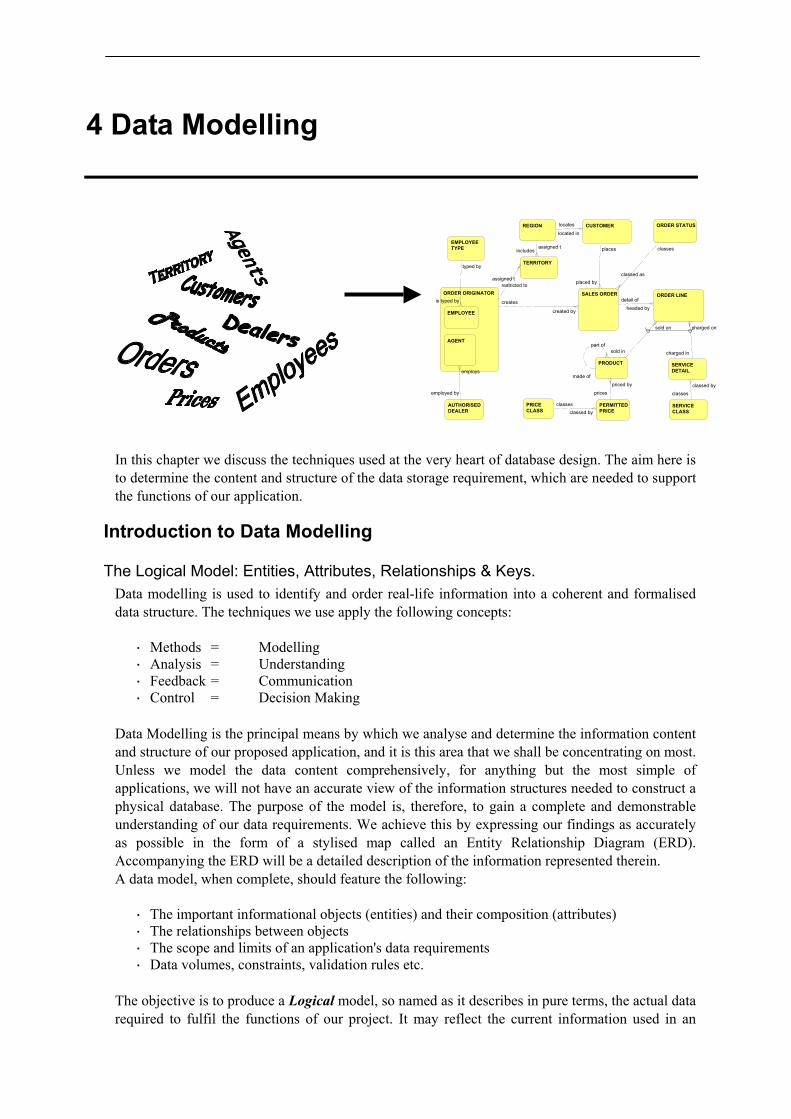
In this chapter we discuss the techniques used at the very heart of database design. The aim here is to determine the content and structure of the data storage requirement, which are needed to support the functions of our application.
Introduction to Data Modelling
The Logical Model: Entities, Attributes, Relationships & Keys. Data modelling is used to identify and order real-life information into a coherent and formalised data structure. The techniques we use apply the following concepts:
· Methods = Modelling · Analysis = Understanding · Feedback = Communication · Control = Decision Making
Data Modelling is the principal means by which we analyse and determine the information content and structure of our proposed application, and it is this area that we shall be concentrating on most. Unless we model the data content comprehensively, for anything but the most simple of applications, we will not have an accurate view of the information structures needed to construct a physical database. The purpose of the model is, therefore, to gain a complete and demonstrable understanding of our data requirements. We achieve this by expressing our findings as accurately as possible in the form of a stylised map called an Entity Relationship Diagram (ERD). Accompanying the ERD will be a detailed description of the information represented therein. A data model, when complete, should feature the following:
· The important informational objects (entities) and their composition (attributes) · The relationships between objects · The scope and limits of an application's data requirements · Data volumes, constraints, validation rules etc.
The objective is to produce a Logical model, so named as it describes in pure terms, the actual data required to fulfil the functions of our project. It may reflect the current information used in an
TERRITORY
SERVICECLASS
PRICECLASS
PERMITTEDPRICE
ORDER STATUSREGION
SALES ORDERORDER ORIGINATOR ORDER LINE
EMPLOYEETYPE
CUSTOMER
AUTHORISEDDEALER
PRODUCT SERVICEDETAIL
EMPLOYEE
AGENT
includesassigned t
assigned trestricted to
classed byclasses
classed byclasses
priced by
prices
classed as
classes
located in
locates
charged on
charged in
sold on
sold inpart of
made of
is typed by
typed by
headed by
detail of
placed by
places
created by
creates
employs
employed by

The ERD
organisation, or existing application, or the projected requirements for something new. Although, as we shall see, the logical model uses many of the concepts found in an RDBMS implementation, it is quite distinct from a Physical model, which by contrast, is a design for implementation comprising physical database tables and associated objects.
Logical vs. Physical Models A logical model, although formal, is free from practical considerations imposed by the proprietary software in which a database is implemented. It is, therefore, not software specific and not bound by any product-related constraints, restrictions or special features. A physical model is (or should be) a derivation of a logical model. It encompasses the software constraints, restrictions and features required for an implementation to support the functional requirements of our application. In reality, the physical model (table map) will vary from being very similar to the logical model through to being quite different - depending upon the RDBMS product and practical design considerations.
Producing an Entity Relationship Diagram (ERD) Entity modelling is the basis of data modelling. This method is employed to aid the construction of the logical model and it is also the single most useful technique in database design and we strongly recommend that the reader masters the basics of this indispensable technique. It should become as familiar to the database designer as a circuit diagram is to an electronics engineer. The technique, which can be used irrespective of the intended database product, is particularly complimentary to RDBMS methodology because of the similarity of approach in the way data are organised. We would advocate that effective entity modelling is essential to successful RDBMS database design, as it is performed at the conceptual stage when we establish the informational requirements and determine an organisational framework for the data. If our understanding of the logical structureor application is flawed - so will be the structure of the database, which we are constructing. As we have seen in the previous chapter, there are a number of very good reasons for Entity Modelling and producing an Entity Relationship Diagram (ERD = Data Model). A good ERD has intrinsic value to an organisation in its own right and it is usually considered to be a 'deliverable' in the early stages of a project. An accurate logical model can be reusable and is likely to persist beyond the life of a physical system. Here are some good reasons for doing one: · It allows the analyst or designer to quickly build up a high level picture of the important data
objects and their interrelationships that already exist (or will be required) within an enterprise or database application.
· An Entity model, when presented as an ERD, should be easy to interpret and can, after only
limited explanation, be readily understood by the business/client community. · It can be presented to the business /client who can verify that we have considered, and
understood the importance of, contents of, and relationships between the significant data components.
Tip: When embarking on a data modelling exercise, it is a wise thing to put knowledge of thephysical implementation process aside. We will be thinking on a higher plane. The time forthe physical mapping of a pure data model to an RDBMS comes much later. Our first requirement is to thoroughly understand the information content of our project.

Modelling Definitions
· Along with the itemised data content of each entity, we will have identified the primary and foreign keys associated with the data, prior to the physical design.
· It forces compliance with existing 'Business rules' concerning data, and will doubtless generate
a few more, which had perhaps not been formally considered, as relationships are identified between different groups of data.
· It can be used as a 'testbed' which we can verify for completeness and accuracy of structure by
ensuring that it can support each of the required component functions and processes. · Having produced a logical map of the data structures the technique enables us to design ‘out’
duplications and other discrepancies in existing structures. · The data model is developed independently of the eventual database tool and will outlive the
current technology. It is intended to be a conceptual map of data organisation and, as such, may have great intrinsic value to a business in its own right (see Corporate Model)
· For most applications, the physical model will map closely the entity model and, thus, much of
the hard work designing the physical model will have been done at the data modelling stage.
Definitions Before we progress any further, it is worthwhile defining at the outset, some of the key objects, which we shall be working. Entity
A uniquely identifiable information object, real or conceptual, which is of distinct and enduring significance to the enterprise. Examples of entities are SALESMAN, SALES ORDER, PRODUCT, VEHICLE, CUSTOMER, LOCATION and WORK PLAN. An entity is characterised by constituent informational elements known as attributes, which together identify and describe any occurrence of the entity.
Attribute A characteristic or element of information which is used to identify, classify, quantify or describe any occurrence (instance) of an entity. Examples: Surname, Date of Birth, Product Code, and Quantity Sold. Using our Cars example, 'VEHICLE' is the name of an entity, Colour might be one of its attributes. Note that attributes must be unique within the same entity but may be repeated in different entities.
Domain
A named structure used to specify an attribute or group of attributes that recur within the database. It provides the specification for format, meaning, validation, etc.
Instance
A single occurrence of an entity (it corresponds to a record on a file or database table). If the SALESMAN entity contained the attribute 'First Name' then examples of instances might be 'Michael', 'Jane', 'Ahmed' etc.
Relationship
Note: If an entity model or component entity models cover the entire information spectrum ofan organisation it is often called a Corporate model.
The ERD
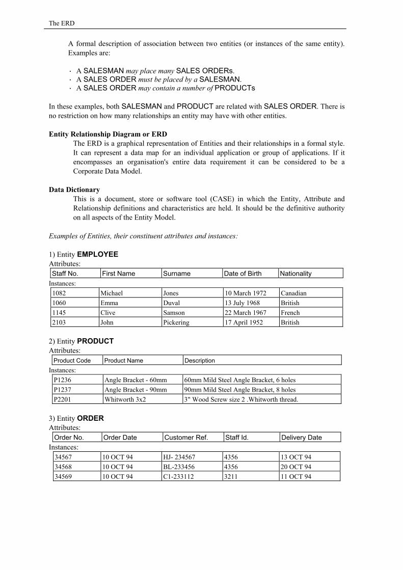
A formal description of association between two entities (or instances of the same entity). Examples are: · A SALESMAN may place many SALES ORDERs. · A SALES ORDER must be placed by a SALESMAN. · A SALES ORDER may contain a number of PRODUCTs
In these examples, both SALESMAN and PRODUCT are related with SALES ORDER. There is no restriction on how many relationships an entity may have with other entities. Entity Relationship Diagram or ERD
The ERD is a graphical representation of Entities and their relationships in a formal style. It can represent a data map for an individual application or group of applications. If it encompasses an organisation's entire data requirement it can be considered to be a Corporate Data Model.
Data Dictionary This is a document, store or software tool (CASE) in which the Entity, Attribute and Relationship definitions and characteristics are held. It should be the definitive authority on all aspects of the Entity Model.
Examples of Entities, their constituent attributes and instances: 1) Entity EMPLOYEE Attributes: Staff No. First Name Surname Date of Birth Nationality
Instances: 1082 Michael Jones 10 March 1972 Canadian 1060 Emma Duval 13 July 1968 British 1145 Clive Samson 22 March 1967 French 2103 John Pickering 17 April 1952 British
2) Entity PRODUCT Attributes:
Product Code Product Name Description Instances:
P1236 Angle Bracket - 60mm 60mm Mild Steel Angle Bracket, 6 holes P1237 Angle Bracket - 90mm 90mm Mild Steel Angle Bracket, 8 holes P2201 Whitworth 3x2 3" Wood Screw size 2 .Whitworth thread.
3) Entity ORDER Attributes:
Order No. Order Date Customer Ref. Staff Id. Delivery Date Instances:
34567 10 OCT 94 HJ- 234567 4356 13 OCT 94 34568 10 OCT 94 BL-233456 4356 20 OCT 94 34569 10 OCT 94 C1-233112 3211 11 OCT 94

Modelling Relationships
Modelling Entities and Relationships We begin the modelling process after, and sometimes during, the identification of the principal entities which our organisation (or application) requires to store in order to support its intended processing functions. The model begins with a blank piece of paper and a pencil. Entities are usually drawn as "soft" boxes on paper (or IE/CASE tool); by ‘soft’ we mean a rectangle with rounded corners. Relationships between entities are indicated explicitly by drawing lines between related boxes (entities). These lines are stylised and are annotated to describe the nature of the relationships between them. We begin to construct our ERD by drawing our entity boxes and indicating relationships between them with connecting lines:
Note: There are various diagram notations in use – the one demonstrated here is the one we recommend. The above diagram illustrates what we might see on part of an ERD. It describes two entities: DOCTOR and PATIENT and the relationship between them. The joining line indicates that they are associated and the meaning of their association is described by the relationship names assigned to them. Note that the nature of the relationship line is different at each end. We shall explore the full meaning of this notation presently but suffice to say that the 'Crowsfoot' notation used on the PATIENT end indicates a 'many' relationship whilst the unadorned end attached to DOCTOR implies only 'one'. The implied meaning of this diagram is that "A doctor may minister to many patients and a patient must only be registered with one Doctor". These descriptions are termed Business Rules with which the relationship line complies.
Identifying Entities Identifying the important entities and their attributes is akin to embarking on a voyage of discovery. Often we will be seeking out structures from a mass of disorganised data originating from diverse sources. After some practice and experience, however, identifying entities becomes virtually an intuitive process and the analyst can usually spot them readily. Describing just how to identify them to the inexperienced modeller is, however, not such an easy matter. It is easier to demonstrate this process by reference to specific examples, of which the reader will find ample material in the case study in Chapter 13. Basically, the process is as follows: The analyst gathers as much information about an application or business area as is necessary to be in a position to feel confident that the essential ingredients of the project are at hand. The information will come from a variety of sources, from documents, interviews with management and users, file layouts, pro-formae etc. We start by making a list of likely candidates for entities from our material. Our provisional entities will take on a familiar form, they generally have nouns for names and the attributes that characterise them are generally descriptive and qualifying. For example:
PATIENT DOCTORregistered with
ministers to
Soft box signifies entity
Relationship indicator ARelationship name B
Relationship indicator BRelationship name AEntity A
Entity B
A Simple Data Model
Entity Name: Nouns: e.g. EMPLOYEE, PRODUCT, CUSTOMER, JOURNEY Attributes: Type, Description, Start Date, End Date, specific value Provisionally identified entities will have at least two attributes, be capable of clear definition and be capable of being identified as unique instances (occurrences).
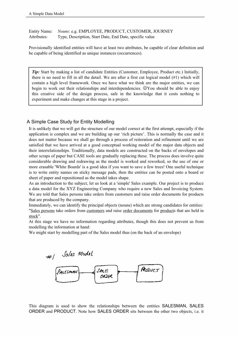
A Simple Case Study for Entity Modelling It is unlikely that we will get the structure of our model correct at the first attempt, especially if the application is complex and we are building up our ‘rich picture’. This is normally the case and it does not matter because we shall go through a process of reiteration and refinement until we are satisfied that we have arrived at a good conceptual working model of the major data objects and their interrelationships. Traditionally, data models are constructed on the backs of envelopes and other scraps of paper but CASE tools are gradually replacing these. The process does involve quite considerable drawing and redrawing as the model is worked and reworked, so the use of one or more erasable 'White Boards' is a good idea if you want to save a few trees! One useful technique is to write entity names on sticky message pads, then the entities can be posted onto a board or sheet of paper and repositioned as the model takes shape. As an introduction to the subject, let us look at a 'simple' Sales example. Our project is to produce a data model for the XYZ Engineering Company who require a new Sales and Invoicing System. We are told that Sales persons take orders from customers and raise order documents for products that are produced by the company. Immediately, we can identify the principal objects (nouns) which are strong candidates for entities: "Sales persons take orders from customers and raise order documents for products that are held in stock". At this stage we have no information regarding attributes, though this does not prevent us from modelling the information at hand: We might start by modelling part of the Sales model thus (on the back of an envelope)
This diagram is used to show the relationships between the entities SALESMAN, SALES ORDER and PRODUCT. Note how SALES ORDER sits between the other two objects, i.e. it
Tip: Start by making a list of candidate Entities (Customer, Employee, Product etc.) Initially,there is no need to fill in all the detail. We are after a first cut logical model (#1) which willcontain a high level framework. Once we have what we think are the major entities, we canbegin to work out their relationships and interdependencies. ☺You should be able to enjoythis creative side of the design process, safe in the knowledge that it costs nothing toexperiment and make changes at this stage in a project.
Modelling Relationships
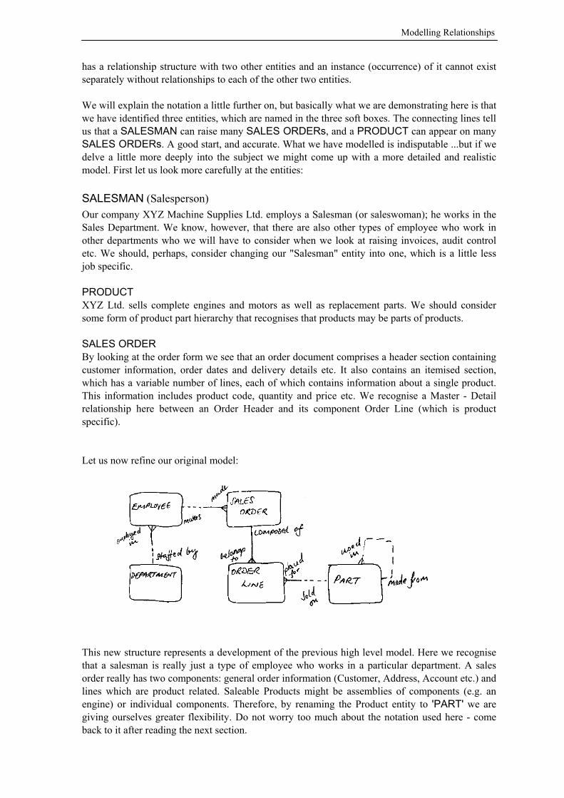
has a relationship structure with two other entities and an instance (occurrence) of it cannot exist separately without relationships to each of the other two entities. We will explain the notation a little further on, but basically what we are demonstrating here is that we have identified three entities, which are named in the three soft boxes. The connecting lines tell us that a SALESMAN can raise many SALES ORDERs, and a PRODUCT can appear on many SALES ORDERs. A good start, and accurate. What we have modelled is indisputable ...but if we delve a little more deeply into the subject we might come up with a more detailed and realistic model. First let us look more carefully at the entities: SALESMAN (Salesperson) Our company XYZ Machine Supplies Ltd. employs a Salesman (or saleswoman); he works in the Sales Department. We know, however, that there are also other types of employee who work in other departments who we will have to consider when we look at raising invoices, audit control etc. We should, perhaps, consider changing our "Salesman" entity into one, which is a little less job specific. PRODUCT XYZ Ltd. sells complete engines and motors as well as replacement parts. We should consider some form of product part hierarchy that recognises that products may be parts of products. SALES ORDER By looking at the order form we see that an order document comprises a header section containing customer information, order dates and delivery details etc. It also contains an itemised section, which has a variable number of lines, each of which contains information about a single product. This information includes product code, quantity and price etc. We recognise a Master - Detail relationship here between an Order Header and its component Order Line (which is product specific). Let us now refine our original model:
This new structure represents a development of the previous high level model. Here we recognise that a salesman is really just a type of employee who works in a particular department. A sales order really has two components: general order information (Customer, Address, Account etc.) and lines which are product related. Saleable Products might be assemblies of components (e.g. an engine) or individual components. Therefore, by renaming the Product entity to 'PART' we are giving ourselves greater flexibility. Do not worry too much about the notation used here - come back to it after reading the next section.

A Simple Data Model
The model here is now more explicit. We show that we now understand the nature of an order and the fact that the salesman (or saleswoman), is really just a type of employee. Our original conception of product was over simplified. The model is still not complete, particularly in the Product/Part area. For example, XYZ may also service machinery based upon a raised order. How would service charges fit in? Also there is nothing to distinguish Salesmen from other types of employees - if this is significant to the business. We could, however, just about build an order database from the information supplied here. The model is reasonably generalised; we could connect the EMPLOYEE entity to other structures (service tasks, skills, employment record etc.) without having to model separate job categories. We could also incorporate a parts / stock inventory without too much difficulty.
More Information about Entities
Entity Naming & Conventions There are no hard and fast rules about naming entities, however, it helps if you adopt and adhere to a convention such as the following: · An entity name should, where possible, be a noun and take the singular form because when we
look at relationships between entities, we express our analysis on the basis of a single instance (occurrence) avoiding ambiguity and making reading an ERD simpler.
· Entity names must be unique. The uniqueness should be at least across the application and across your organisation if possible, this will again avoid possible confusion and ambiguity.
· Names should be clear and concise. Use full words rather than abbreviations unless they are of a technical nature or 'culturally' significant to the organisation.
· Remember entities are business objects not database tables. We do not need to scrimp on bits and bytes by codifying as in the 'old days' of data processing. Non-ambiguity, specific definitions and clarity are the watchwords.
· It does not matter whether we use UPPER, lower or mixed case for our naming convention as long as there is consistency.
What do we Need to Know About an Entity? a) Description Each entity should be accompanied by a precise and unambiguous definition which describes its raison d’être. This should not be taken lightly as misunderstanding the precise scope and purpose of an entity is very common. For example, what do we mean by an entity called Employee? Does it include: executives, temporary staff, agents (on commission), sub-contracted workers, agency staff, and students, work experience staff etc.? This may not be significant perhaps in respect of order taking but, taken in a personnel context, there may be significant differences for matters of pensions, benefits, salaries, overtime etc. The precise definition of the EMPLOYEE entity must therefore provoke some thought. We might settle for: "Any person recognised as performing regular duties at the behest of XYZ Engineering Ltd." This is obviously a catchall definition but it is unambiguous. Note that by specifying the company we are specifically excluding parent and child companies - should they exist. Because we have applied some thought to the definition, we are aware that there may be some problems to solve in the personnel area, these can be addressed when we add the attributes and model relationships in the ERD.
Note: There is rarely just a single solution to a data modelling problem and different modellersmay construct different solutions and hence differently shaped ERDs. This said, we wouldexpect there to be consensus over the main entities and their attributes.
Modelling Relationships
b) Primary Key: Our entities will require, at the very least, a PK (= UID) whose selection will be considered more fully in a later section but suffice to say that one or more attributes (singly or in combination) will be employed for this task. For example, in the entity PART, a Part Number would be the obvious choice for the primary key.
Attributes
Attribute Naming and Conventions Again there are only a few rules to consider: · Attribute names should be unique within an entity. They need not, however, be unique across
entities. For example, an attribute called "Description" may occur repeatedly in different entities. Note, however, that their meaning and format will not necessarily be the same across all entities*.
· Use proper words instead of abbreviations and acronyms, unless they are accepted technical terms or well established in the Business' culture.
· As with naming entities, the text style of an attribute name does not matter as long as there is consistency. In this book we use mixed case attribute names. There is no need to use hyphens (-) or underscores (_) between words. We are not writing COBOL.
* But see ‘Domains’
What Information do we Need to Know About an Attribute? · Its assigned name (as discussed above) · A concise definition · Any synonyms that it might be given for reasons of regional variation or common usage. For
example Car : Auto, Agent : Commisionary, Goods : Products, Account Holder : Customer, Pupil : Student
· Its Optionality (is a value for it mandatory or optional) · Its type and format (alphanumeric, date, etc.)
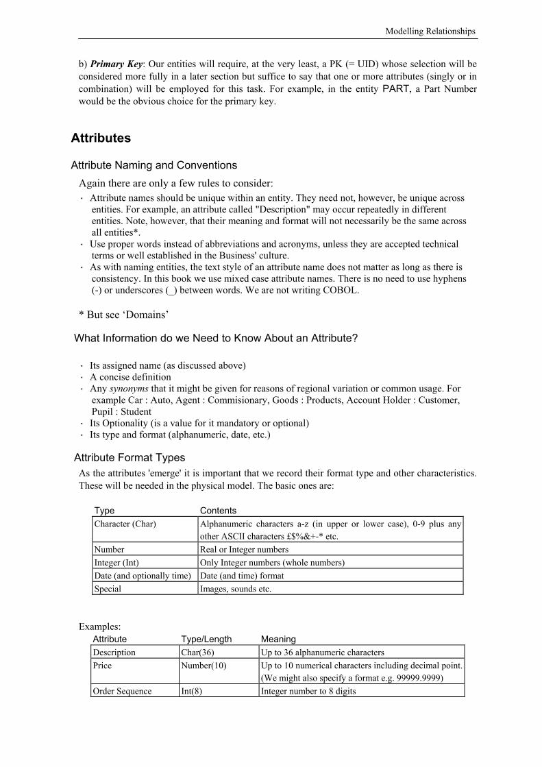
Attribute Format Types As the attributes 'emerge' it is important that we record their format type and other characteristics. These will be needed in the physical model. The basic ones are:
Type Contents Character (Char) Alphanumeric characters a-z (in upper or lower case), 0-9 plus any
other ASCII characters £$%&+-* etc. Number Real or Integer numbers Integer (Int) Only Integer numbers (whole numbers) Date (and optionally time) Date (and time) format Special Images, sounds etc.
Examples:
Attribute Type/Length Meaning Description Char(36) Up to 36 alphanumeric characters Price Number(10) Up to 10 numerical characters including decimal point.
(We might also specify a format e.g. 99999.9999) Order Sequence Int(8) Integer number to 8 digits
Attribute Definitions
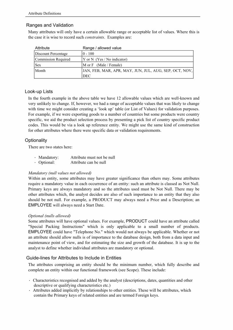
Ranges and Validation Many attributes will only have a certain allowable range or acceptable list of values. Where this is the case it is wise to record such constraints. Examples are:
Attribute Range / allowed value Discount Percentage 0 - 100 Commission Required Y or N (Yes / No indicator) Sex M or F (Male / Female) Month JAN, FEB, MAR, APR, MAY, JUN, JUL, AUG, SEP, OCT, NOV,
DEC
Look-up Lists In the fourth example in the above table we have 12 allowable values which are well-known and very unlikely to change. If, however, we had a range of acceptable values that was likely to change with time we might consider creating a ‘look up’ table (or List of Values) for validation purposes. For example, if we were exporting goods to a number of countries but some products were country specific, we aid the product selection process by presenting a pick list of country specific product codes. This would be via a look up reference entity. We might use the same kind of construction for other attributes where there were specific data or validation requirements.
Optionality There are two states here:
· Mandatory: Attribute must not be null · Optional: Attribute can be null
Mandatory (null values not allowed) Within an entity, some attributes may have greater significance than others may. Some attributes require a mandatory value in each occurrence of an entity: such an attribute is classed as Not Null. Primary keys are always mandatory and so the attributes used must be Not Null. There may be other attributes which, the analyst decides are also of such importance to an entity that they also should be not null. For example, a PRODUCT may always need a Price and a Description; an EMPLOYEE will always need a Start Date. Optional (nulls allowed) Some attributes will have optional values. For example, PRODUCT could have an attribute called "Special Packing Instructions" which is only applicable to a small number of products. EMPLOYEE could have "Telephone No." which would not always be applicable. Whether or not an attribute should allow nulls is of importance to the database design, both from a data input and maintenance point of view, and for estimating the size and growth of the database. It is up to the analyst to define whether individual attributes are mandatory or optional.
Guide-lines for Attributes to Include in Entities The attributes comprising an entity should be the minimum number, which fully describe and complete an entity within our functional framework (see Scope). These include: · Characteristics recognised and added by the analyst (descriptions, dates, quantities and other
descriptive or qualifying characteristics etc.) · Attributes added implicitly by relationships to other entities. These will be attributes, which
contain the Primary keys of related entities and are termed Foreign keys.
Entities & Attributes
What Not to Include as Attributes This subject is somewhat more problematic than what attributes to include and covers areas, which reinforce good modelling practice. Below are examples of what should not be included in a Data Model. 1) Attributes, which are calculated, transformed or otherwise derivable from other sources, be they within the entity or from other related entities. Logically, there is no need to hold them because by knowing the formula or transformation method we can create the value on demand. This information should be recorded in the functions or processes, which use the information in these entities. Examples: Calculated values
On an invoice line held in an entity called INVOICE LINE the cost of the goods or services is usually Price x Quantity; there is no need, therefore, to hold this cost as an attribute as it can be readily be calculated as required.
Cumulative values Although it may be desirable to hold some cumulative values (batch controls etc.); it is good practice not to hold them as attributes on the logical model if at all possible. Maintaining calculated running totals etc. requires procedural logic. If the components of a cumulative value are liable to be altered (e.g. correction to number of goods ordered) then the cumulative value has to be recalculated and this requires more procedural logic. If they really are required for say, performance reasons, the decision should be made during the physical design stage (see Chapter 7).
Transformed values By transformed we mean some character or mathematical translation. We would not, for example, strip out and hold as a separate attribute part of a code in another attribute (we don't want structured codes anyway). We would not hold character translations or concatenations. For example, if we had First Name, middle Initial and Surname) we would not hold Name (First Name||" "||Initial||" "Surname) as a separate attribute.
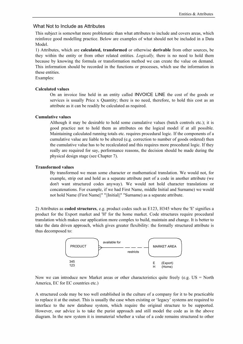
2) Attributes as coded structures, e.g. product codes such as E123, H345 where the 'E' signifies a product for the Export market and 'H' for the home market. Code structures require procedural translation which makes our application more complex to build, maintain and change. It is better to take the data driven approach, which gives greater flexibility: the formally structured attribute is thus decomposed to:
Now we can introduce new Market areas or other characteristics quite freely (e.g. US = North America, EC for EC countries etc.) A structured code may be too well established in the culture of a company for it to be practicable to replace it at the outset. This is usually the case when existing or ‘legacy’ systems are required to interface to the new database system, which require the original structure to be supported. However, our advice is to take the purist approach and still model the code as in the above diagram. In the new system it is immaterial whether a value of a code remains structured to other
PRODUCT available for
restricts MARKET AREA
345 123 E (Export)
H (Home)
Attribute Definitions
systems. Any processes we build can derive the code's characteristics by its classifying relationship - regardless of the fact that the code is still structured to outside systems. To these outside systems the code can still be translated in the same manner as previously. In the future, the structured form of a data value can be dropped with no effect on the new system and its processes. 3) Attributes which are not used in any of the specified functions. If there are no functions that require the presence of a particular attribute it should not be included in the entity. Inclusion of attributes should be justifiable: if an attribute is not reported on or manipulated in any of the known processes, there is no point in its inclusion: it simply clutters up the data model. 4) Denormalised attributes: Denormalisation is a complex area of database design and is dealt with more fully in later sections of this book (see 'Advanced Entity Modelling' and 'Getting Physical'). Our logical model should be ‘normalised’ as far as possible, that is, an attribute with a unique value in an instance should be represented in a single entity only. For example, if a PRODUCT entity includes Product Code, Name, Description and Type, in our ORDER LINE entity we would include the attribute Product Code (as a foreign key), but we would not include a repetition of Name, Description or Type for the product. These values can be looked up in the PRODUCT entity when required via the Product code foreign key (which is the primary key to PRODUCT'). If we follow this rule, the structure of ORDER LINE in respect of PRODUCT is said to be normalised. Logically, it is unnecessary, and most undesirable, to duplicate attributes for information that can be obtained elsewhere. There are, however, conditions when, for practical reasons, replication of attributes between entities may be advantageous; this is called denormalisation. These circumstances should only be considered in the very final stages of the logical model, or, more usually, in the physical database design.
Key Point: Remember: we are constructing a logical model – which should be normalised andholding the barest minimum to describe the information. Where procedures are required totransform or translate data, identify and document them. Do not specify their products asattributes. The physical model (database structure) is a different matter; for performance orprocedural reasons it may be advantageous to hold a calculated or ‘denormalised’ value. Thereare certainly differences in database types (OLAP vs. OLTP). These decisions come later.
Domains
Domains We have looked at the definition and roles for entities and attributes and how they are used to define an information model. However, there are other ways of looking at and defining data constructs. Domains usually operate below entity level and can be used to define sets of specifications that apply to a repeating attribute or a coherent group of attributes. These include:
· Attribute content · Format · Validation rules · Constraints · List of values · Range (numeric)
Although entities must be unique, and attributes unique within an entity, attributes, or similar attributes may appear across a number of entities. For example, within an application, the following attributes / groups may appear a number of times:
· Address · Date / Time · Description · Discount · Name (person’s) · Monetary value
These are but a few. We would prefer and expect that the definition of these attributes will take a common form across the database – for obvious reasons. By defining a domain to which they will conform is one way of achieving this consistency. For example, a domain called ‘Discount’ would be used by attributes which may be called Discount or at least have the meaning of discount (Sale Discount, Price Discount, Volume Discount, etc.). It might be defined as:
Definition Percentage (to be applied to an original value) Format Numeric 999.99 Valid Range 0 - 100
A domain can have more structure. E.g. PersonName, may comprise the following attributes:
Salutation* Character(6) First Name Character(24) Middle Initials Character(4) Last Name Character(24)
* May have values restricted to a list of permitted values (Mr. Prof. Dr. Ms., etc.) Address is always an interesting one and subject to many national and international standards, it may have a simple attribute data type definition:
Line One Character(36) Line Two Character(36) District Character(36) Town Character(24) Post Code Character(12) County Character(24) Country Character(24)

Domains
Within this simple attribute definition will be the standard business rules, for example: · House / Street number may be before or after the street name (Country specific) · The position of Town / Post / Zip Code is also country specific · The format of post code / zip code is country specific · The need for country will depend upon whether posting is within or outside the country of
postage
And it gets a lot more complicated than this. All these rules and definitions can be placed within the domain properties.
Why use Domains? It is obviously good practice to standardise use of common attribute types across a database design for a number of good reasons – the properties and functions of the domain must be applicable across all the attributes within them, across the database. If you are using CASE and application generation tools, it makes even more sense. Domains are defined in CASE and then attributes and groups of attributes will be assigned a domain, thus the attribute will assume all the properties of the domain. When code is written / generated, rules and constraints are automatically applied and thus rigour and consistency are applied to the application being built. For example, if a validation range or list of values is assigned to the domain, the attribute(s) using it will have this validation procedure applied automatically during the build process.
Key Point: In many respects, a domain corresponds with the Object Oriented (OO)definition of a ‘Class’. Many designers make the mistake of thinking that a classcorresponds with an entity – it does not. Note that, contrary to ill-informed belief,OO and the Entity / Attribute view of the world, are not mutually exclusive – butcomplimentary and necessary.
Warning: Note the ‘Domain’ concept is not particularly well implemented inRDBMS packages or application generators. It may be missing in the lessexpensive examples
Principles of Normalisation
The Principles of Normalisation The concept of normalisation originated with Dr Ted Codd in the early 1970's when he laid down a number of criteria or rules which defined the Relational Model. In essence, the normalisation process is the method by which a data model is constructed and validated to ensure that each attribute is correctly assigned to one, and only one, entity. This eliminates data redundancy (repetition) and ensures that relationship structures are correctly identified. There are a number of "Normal Forms" which, by convention, are numbered from one upwards (presently more than 7 have been mooted). In most models, however, taking the structure to the 'Third Normal Form' is usually quite sufficient. Without reference to examples, understanding the meanings of the various normal forms is difficult. For completeness, here are descriptions of the first three Normal Forms:
First Normal Form (1NF)
Each attribute within an entity, that is not a key, should contain only a single value (no repeating groups)
Second Normal Form (2NF)
The entity should be in 1NF and every attribute which is not itself used in a key, depends on the entire primary key - there being no dependencies on any part of the PK
Third Normal Form (3NF)
The entity should be in 2NF and each attribute which is not part of the primary key is dependent solely on the PK and not on any other non PK attributes
Unique Identifiers (UIDs). The Role of the Primary Key In the introduction we discussed the importance of primary (PK) and foreign keys (FK) in relational database methodology. A vital part of Entity Modelling is the determination of unique identifiers. Here we look at which attribute or attributes to use for identifying unique instances of an entity. Why do we need to uniquely identify each instance of an entity? Logically, we need to be able to reference directly each instance of an entity unambiguously a) in its own right and b) to enable us to define relationships between entities. For example, if we look up the details of Mr. John Smith, we do not want the employment record of Mrs. Jane Brown and the home address of Mr. Fred Bloggs. When information is spread through entities it is vital that we are able to rely on our relationships being able to connect the correct instances. This is called Referential Integrity. In summary, without the ability to uniquely identify instances, we are unable to:
· Locate with any confidence any specific item of information · 'Traverse' relationships to locate related information
Note: A good ERD will be in Third Normal Form. Following the normalisation rules explicitly isquite a chore. The methods described in this book follow them implicitly and steer the readertoward a model in 3NF. However, when modelling is complete, you can confirm the validity ofthe model by checking each entity against the rules.
Primary Key
© Domanski & Irvine 2000-2005 28
Choosing a Primary Key (PK) We select an entity's PK by looking for an attribute or the simplest combination of attributes that will give us this. For example:
· In the SALES ORDER entity we would choose the Order Number attribute as no two orders will have the same order number
· For the EMPLOYEE entity, Staff No. would be the logical choice as each employee has a unique staff number
These are relatively simple examples but beware, the choice is not always as straightforward. In the real world it can be difficult to find a single unique 'natural' identifier that we can say with absolute certainty will always be unique. This is particularly true when dealing with people-related information (those readers used to dealing with customer and contact information will have discovered this). For example, Names are not unique and UK National Insurance numbers are not always applicable (e.g. overseas visitors) and note that many attribute values are likely to change with time.
Types of Primary Key There are three main types to consider:
A. The Simple (Natural) key Order Numbers and Staff Numbers are examples of simple keys. A simple key is a natural attribute, which, on its own, provides a unique reference to an entity occurrence. Examples are Order No. for ORDER, Staff No. for EMPLOYEE etc., these must be unique and not be liable to vary with time.
B. The Concatenated or Composite key If no single attribute provides a unique reference, it is quite in order to use two or more attributes in combination, which, when concatenated, form a unique reference. For example, there may be many ORDER LINEs for a given order. It would be worth considering using Order No. + Product Code to form a unique key. C. The Artificial key If it is not possible to find an attribute or combination of attributes, the best course of action is to create a special attribute with the specific purpose of providing a primary key. A sequence number of some form is commonly used for this purpose: a number is incremented as new occurrences are created. This technique is used quite commonly in the real world; sequence or serial numbers are created to uniquely identify a person or object where identification would otherwise be difficult. Examples are Staff No., Product Serial No., Car Registration No., National Insurance No., Membership No. and a whole host of others. Consider again the ORDER LINE entity: if it is at all likely that the same product can occur more than once on the same order (which can happen), our suggested concatenated key of Order No + Product Code may be of no use as the combination would not be unique in all cases. It would be better to create an artificial attribute such as "Order Line No.", each occurrence of an order line within an order being given its own (unique) line number within an ORDER. An effective primary key for ORDER LINE would thus be Order No. + Order Line No.
Artificial Primary Key
Another example of an Artificial Primary Key A simpler example of an artificial key might be as follows. We are required to create a customer database. A customer might be an individual or organisation. The customer is, over time, likely to move house / premises and may even change name.
Question How do we uniquely identify a customer? Answer This is a notoriously difficult problem for many companies - primarily because the
term 'Customer' means different things to different people (Accounts, Marketing, Dispatch etc.). We should consider inventing a Customer Reference No.
Why? It can be difficult to find a convenient "handle" for customers. Names are not unique and, in any case, customers may change name and so this rules it out as a component for a primary key. Addresses are notoriously difficult to maintain and liable to change and so should not be used. Not all customers will have registered trade names, company numbers etc. so we really have a problem in finding a suitable attribute or attribute combination that has some enduring uniqueness. A unique Customer Reference No. On the other hand can be assigned to our otherwise varying "cluster" of attributes, which describe a customer through time. It can be printed on correspondence and so is a very useful mutual point of reference between a customer and our company (see section “People and Organisations”)
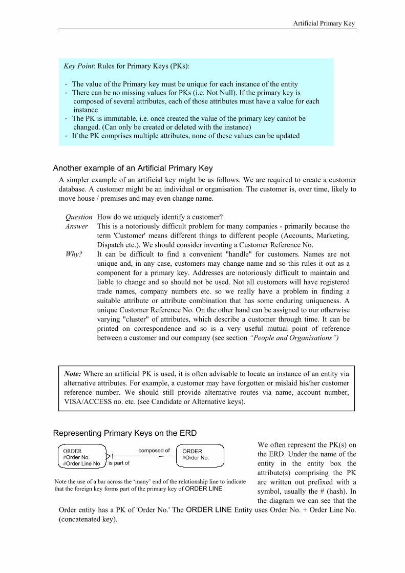
Representing Primary Keys on the ERD We often represent the PK(s) on the ERD. Under the name of the entity in the entity box the attribute(s) comprising the PK are written out prefixed with a symbol, usually the # (hash). In the diagram we can see that the
Order entity has a PK of 'Order No.' The ORDER LINE Entity uses Order No. + Order Line No. (concatenated key).
Key Point: Rules for Primary Keys (PKs): · The value of the Primary key must be unique for each instance of the entity · There can be no missing values for PKs (i.e. Not Null). If the primary key is
composed of several attributes, each of those attributes must have a value for each instance
· The PK is immutable, i.e. once created the value of the primary key cannot be changed. (Can only be created or deleted with the instance)
· If the PK comprises multiple attributes, none of these values can be updated
Note: Where an artificial PK is used, it is often advisable to locate an instance of an entity viaalternative attributes. For example, a customer may have forgotten or mislaid his/her customerreference number. We should still provide alternative routes via name, account number,VISA/ACCESS no. etc. (see Candidate or Alternative keys).
ORDER #Order No.
is part of
composed ofORDER #Order No. #Order Line No
Note the use of a bar across the ‘many’ end of the relationship line to indicate that the foreign key forms part of the primary key of ORDER LINE
Primary Key
© Domanski & Irvine 2000-2005 30
Further Advice on Creating a Primary Key Contrary to what we might expect, determining unique identifiers for entities is no trivial matter. When we are presented with a genuinely unique attribute for an entity we should consider ourselves lucky! Most entities are more problematic. We have already seen a couple of examples where there is scope for a dilemma. Remember these two rules: · The Primary key MUST exist on every instance · The value of a PK cannot be changed
We must select primary keys that will have values right from the start, as these are the most important attributes on an entity: to take an order from a customer we must have a Customer PK and an Order PK. We must select primary keys that cannot possibly vary in content – one reason being that these values are held as FKs in other entities – they preserve data integrity.
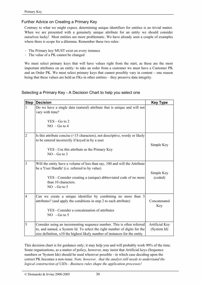
Selecting a Primary Key - A Decision Chart to help you select one Step Decision Key Type 1 Do we have a single data (natural) attribute that is unique and will not
vary with time?
YES – Go to 2 NO – Go to 4
2 Is this attribute concise (<15 characters), not descriptive, wordy or likely to be entered incorrectly if keyed in by a user
YES - Use this attribute as the Primary Key NO – Go to 3
Simple Key
3 Will the entity have a volume of less than say, 100 and will the Attribute be a 'User Handle' (i.e. referred to by value)
YES - Consider creating a (unique) abbreviated code of no more than 10 characters. NO - Go to 5
Simple Key (coded)
4 Can we create a unique identifier by combining no more than 3 attributes? (and apply the conditions in step 2 to each attribute)
YES - Consider a concatenation of attributes NO - Go to 5
Concatenated
Key
5 Consider using an incrementing sequence number. This is often referred to, and named, a System Id. To select the right number of digits for the size definition, x10 the highest likely number of instances for the entity
Artificial Key (System Id)
This decision chart is for guidance only; it may help you and will probably work 90% of the time. Some organisations, as a matter of policy, however, may insist that Artificial keys (Sequence numbers or 'System Ids) should be used wherever possible - in which case deciding upon the correct PK becomes a non-issue. Note, however, that the analyst still needs to understand the logical construction of UIDs - Business rules shape the application processes!
Principles of Normalisation
Candidate or Alternative Keys (CK) A Candidate or Alternative key is an attribute, which, as the name might suggest, provides another means of selecting a particular instance of an entity. Artificial primary keys are all very well, but they do not always permit us to sensibly locate the occurrence of an entity in which we are interested. If we do not know an employee's staff id no., how do we locate his/her records? We search on something more friendly - a candidate key (CK). For example, in the EMPLOYEE entity we would use the Staff No. as the PK because we know that it is allocated uniquely to an employee. We would, however, perhaps stand a >95% chance of obtaining the desired occurrence of EMPLOYEE by referencing the National Insurance No. There may be circumstances when an employee might be taken on initially without a NI no. (e.g. first day of work, workers from abroad etc.). But in most cases this alternative identifying attribute would be effective. It would, therefore, be eligible as a candidate, or alternative key. Another candidate key for EMPLOYEE would be a concatenation of Surname and First Name but remember the bigger the work force, the higher the risk of duplicate names. Candidate keys may not necessarily be unique keys, by that we mean that for a single value of an attribute, we cannot guarantee access to a single target.
The Foreign Key (FK) Foreign Keys in data modelling function in the same way as described for the RDBMS overviewed at the beginning. They are essential to the functioning of relationships between entities. When a relationship is drawn line between two entities it is implicit that one of the entities will carry the PK of the other as an attribute(s). Therefore, a FK will take the same form as the PK on the related entity and not reference a candidate key or any other attribute on the other entity. It is quite common for a FK to another entity to form part of its PK. For example, in our ORDER / ORDER LINE example shown previously, an ORDER will have one or more ORDER LINEs The PK of ORDER is Order Number which will also be the FK in its ORDER LINE. The PK of ORDER LINE will comprise this Order Number plus the Order Line No. (or possibly product). On our ERD we can signify this particular case by putting a bar across the relationship line on the 'many' end. An entity may be connected to none, one or many other entities by relationships and so it may have a number of FK attributes (e.g. the SALES ORDER entity in our XYZ Engineering Ltd. example). As we shall see later, there is a class of entity, which contains solely foreign keys as attributes, this type of entity is used exclusively to resolve 'many:many' relationships. For example, a product may appear on many orders and an order may be for many products, hence many:many. (See Intersection Entities)
Tip: Take care when identifying a primary key. Be wary of selecting data attributes as keys asthese are likely to be changed. Unless absolutely certain that an attribute or set of attributes isunique and will never be liable to change over time, create an artificial attribute specifically foruse as a primary key. An incrementing sequence number is usually used as this will guaranteeuniqueness. System Ids: some designers love them, others hate them. Personally, we are of the former asthey guarantee uniqueness, take up the minimum amount of space for indexes as they areinteger numbers and, are satisfyingly unstructured They do give us more freedom if it is arequirement to duplicate certain parts of the data, or allow nulls, or change what would havebeen primary key data (e.g. CUSTOMER data). Primary keys of more than about 3 attributesstart to become unwieldy - particularly when writing SQL. One drawback, of course, is that anextra attribute is added which will take up extra space; this may be significant for very largetables.
Relationships
© Domanski & Irvine 2000-2005 32
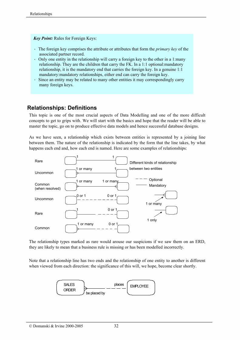
Relationships: Definitions This topic is one of the most crucial aspects of Data Modelling and one of the more difficult concepts to get to grips with. We will start with the basics and hope that the reader will be able to master the topic, go on to produce effective data models and hence successful database designs. As we have seen, a relationship which exists between entities is represented by a joining line between them. The nature of the relationship is indicated by the form that the line takes, by what happens each end and, how each end is named. Here are some examples of relationships:
The relationship types marked as rare would arouse our suspicions if we saw them on an ERD, they are likely to mean that a business rule is missing or has been modelled incorrectly. Note that a relationship line has two ends and the relationship of one entity to another is different when viewed from each direction: the significance of this will, we hope, become clear shortly.
SALESORDER
EMPLOYEE
be placed by
places
Key Point: Rules for Foreign Keys: · The foreign key comprises the attribute or attributes that form the primary key of the
associated partner record. · Only one entity in the relationship will carry a foreign key to the other in a 1:many
relationship. They are the children that carry the FK. In a 1:1 optional:mandatory relationship, it is the mandatory end that carries the foreign key. In a genuine 1:1 mandatory:mandatory relationships, either end can carry the foreign key.
· Since an entity may be related to many other entities it may correspondingly carry many foreign keys.
Common (when resolved)
Uncommon
1 1
1 or many 1
1 or many 1 or many
1 0 or 1
1 or many 0 or 1
0 or 1 0 or 1
OptionalMandatory
Different kinds of relationship between two entities
1 or many
1 only
Rare
Uncommon
Rare
Common

Relationships and Business Rules
A relationship line carries with it three essential pieces of information:
1) Optionality This describes whether an instance (occurrence) of one entity is dependent upon the occurrence of the other entity. Optionality is usually different at either end of the relationship line. In the notation used here a solid line implies a mandatory relationship (must be) and a dashed line implies optional (may be). Example: consider the relationship between EMPLOYEE and SALES ORDER. Reading left to right: A SALES ORDER must be placed by an EMPLOYEE. This reflects the fact that a sales order cannot exist on its own without reference to the employee who raised it. Now reading from the opposite direction: An EMPLOYEE may place a SALES ORDER. An employee may exist irrespective of whether he/she has placed any orders.
2) Cardinality Cardinality, sometimes referred to as the degree, defines the numerical relationship between entities: a single line implies a single instance (1 only). The crowsfoot notation we use here implies multiple occurrences (1 or many): A SALES ORDER must be placed by one and only one EMPLOYEE. An EMPLOYEE may place many SALES ORDERS. Note how 'one and only one ' is emphasised. 3) Relationship Name Each relationship line should carry a pair of descriptive elements, which define the nature of the association between entities. A name is a single word or descriptive phrase; it should always contain a verb such as: owns, owned by, holds, administered by, etc. Examples from our simple model are: A PART is sold on an ORDER LINE. An ORDER LINE is placed for a PART.
Reading Relationship Lines Now if we look at our sales model again we can see that the relationship notation is not at all haphazard or imprecise, it is actually very specific. To read a relationship we construct its definition as an English statement thus: 1) We decide on the pair of entities in question and start at one end of the relationship. e.g. from DEPARTMENT to EMPLOYEE "A DEPARTMENT" 2) Then we add the optionality of the line immediately connected to it "A DEPARTMENT may be" 3) Then we take the relationship name nearest to it "A DEPARTMENT may be staffed by" 4) Next we look at the cardinality of the line connecting to the other entity: "A DEPARTMENT may be staffed by one or many" 5) Then we add the other entity "A DEPARTMENT may be staffed by one or many EMPLOYEEs"

Business Rules
© Domanski & Irvine 2000-2005 34
Lets just analyse the statement another way: "A DEPARTMENT may be1 staffed by2 one or many3 EMPLOYEEs "
1Optionality The line next to DEPARTMENT is dashed indicating an optional relationship = may be.
2 Description Note that there is a verb implying that the entity is doing something. 3 Cardinality The 'crows foot' on EMPLOYEE means 1 or many.
If we now read the relationship from the other direction we get the following: "An EMPLOYEE must be1 employed in2 one and only one3 DEPARTMENT "
1Optionality The solid line next to EMPLOYEE indicates a mandatory relationship = must.
2 Description Note that there is a verb implying that the entity is doing something. 3 Cardinality The single line connected to DEPARTMENT has no crowsfoot so it is
singular.
Relationships and Business Rules Now here is the elegance of the technique; when we read the relationship as just described we are reading a Business Rule for the data. This means that if the Business can provide us with the rules covering two objects we must incorporate them into our model for compliance. If, on the other hand, a priori rules have not been provided, when we model entity relationships we automatically generate Business Rules relating to the entities and relationships. These rules should be verified by the business (or guiding authority) who will check them against reality (or just apply plain common sense). This facet of modelling is tremendously important as, by getting these rules modelled, incorporated correctly and confirmed by the business, we can eliminate a fair proportion of structural errors and weaknesses which tend to occur in the physical database. To correct an error in the ERD takes only a very small fraction of the cost of correcting the error in a physical database structure. Exercises: Try modelling entities and their relationships from these Business Rules. 1) A salesman may be responsible for one or more territories but a territory can only be maintained by one salesman. 2) A person may only possess one passport for one country but may be a citizen of more than one country. 3) An employee may obtain many training qualifications. A subject can be taught for a number of different qualifications.
Note: The above dissection of relationships does emphasise the care, which must be used informulating the ERD. The method is formal and leaves no room for inaccuracy or 'woolly'thinking. As we shall now see, these relationships are synonymous with business rules.Precision is a must. Entities, attributes, relationships and business rules, our building blocks,will eventually translate to a physical model – Accuracy is vital for a successfulimplementation.
Key Point: The above concept is probably the most important one to grasp in the wholeof the design process. Proficiency in the above skill is best acquired by practice, practiceand more practice!

Relationship Modelling
Relationship Modelling Unlike physical modelling (database design), entity modelling is less restrictive on how we model relationships. By this, we mean that this (illustrated in the next diagram) can use the full variety of relationship lines - at least in the initial stages. For example, we might start with the principle: "A salesman may sell many products" and "A product may be sold by many salesmen” It could be modelled thus:
This type of relationship would only be used in the early stages of a design. In the real world, this type of many to many relationship is very rare and, in database terms, it is impossible to implement directly. Note the use of a dashed line: a solid line would have implied mandatory many:many, which is not credible. Although we have just said that the entity modeller has greater freedom of expression in modelling entities and relationships in an ERD than a physical model, in truth we should be travelling in a direction which will inevitably lead us to transform our logical model into a physical database structure. As we shall find out later, physical models are less forgiving than logical ones and although it is true to say "A Sales Person may sell many Products and a Product may be sold by many Sales Persons", we are communicating only part of the truth. The structure that we have modelled is what is termed 'Unresolved', that is, the model has not been taken to its logical conclusion - there is something missing. You cannot implement a structure like this unaltered and if we saw this on an ERD we would know that it was either a primitive model or incorrect, as it contained an 'unresolved' relationship and was not modelled to completeness. In perhaps 98% of all cases we will see only four types of relationship: these are, roughly in order of precedence:
Case i: an instance of the entity A cannot exist without an instance of B ( A must be a child of B), whereas an instance of B can exist independently of A (B may be a parent of A). Hence for any instance of B there may be 0, 1 or more of A. This is the most commonly used form of relationships. For example, a car can exist without a service record – but a service record cannot exist without reference to a car. Case ii: is similar to i except that for an instance of D, only 0 or 1 instances of C may exist. Such a relationship might be used, say, for details of a passport belonging to an individual - assuming that an individual may or may not have a single passport.
1 0 or 1
1 or many 0 or 1
0 or 1 0 or 1
B
iii.
E
D
F
i.
ii.
A
C
G
iv.
PERSON PRODUCT
Business Rules
© Domanski & Irvine 2000-2005 36
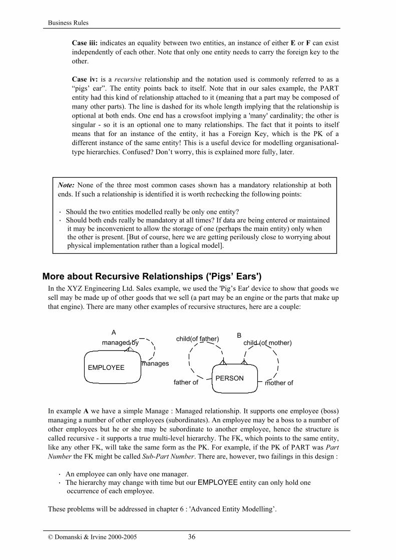
Case iii: indicates an equality between two entities, an instance of either E or F can exist independently of each other. Note that only one entity needs to carry the foreign key to the other. Case iv: is a recursive relationship and the notation used is commonly referred to as a “pigs’ ear”. The entity points back to itself. Note that in our sales example, the PART entity had this kind of relationship attached to it (meaning that a part may be composed of many other parts). The line is dashed for its whole length implying that the relationship is optional at both ends. One end has a crowsfoot implying a 'many' cardinality; the other is singular - so it is an optional one to many relationships. The fact that it points to itself means that for an instance of the entity, it has a Foreign Key, which is the PK of a different instance of the same entity! This is a useful device for modelling organisational-type hierarchies. Confused? Don’t worry, this is explained more fully, later.
More about Recursive Relationships ('Pigs’ Ears') In the XYZ Engineering Ltd. Sales example, we used the 'Pig’s Ear' device to show that goods we sell may be made up of other goods that we sell (a part may be an engine or the parts that make up that engine). There are many other examples of recursive structures, here are a couple:
In example A we have a simple Manage : Managed relationship. It supports one employee (boss) managing a number of other employees (subordinates). An employee may be a boss to a number of other employees but he or she may be subordinate to another employee, hence the structure is called recursive - it supports a true multi-level hierarchy. The FK, which points to the same entity, like any other FK, will take the same form as the PK. For example, if the PK of PART was Part Number the FK might be called Sub-Part Number. There are, however, two failings in this design :
· An employee can only have one manager. · The hierarchy may change with time but our EMPLOYEE entity can only hold one
occurrence of each employee. These problems will be addressed in chapter 6 : 'Advanced Entity Modelling’.
Note: None of the three most common cases shown has a mandatory relationship at bothends. If such a relationship is identified it is worth rechecking the following points: · Should the two entities modelled really be only one entity? · Should both ends really be mandatory at all times? If data are being entered or maintained
it may be inconvenient to allow the storage of one (perhaps the main entity) only when the other is present. [But of course, here we are getting perilously close to worrying about physical implementation rather than a logical model].
A manages
managed by
EMPLOYEE PERSON
mother of father of
child (of mother) child(of father) A B

Relationship Modelling
In example B there are two recursive relationships on the same entity. It models the fact that a person has two parents (one of each sex). We have no problem of time here as in A. We cannot change our (natural) parents!
Note that the PERSON entity illustrating the recursive relationships is an example of an entity : entity case connected by two relationships. It is quite common to have two or more relationships between the same two entities – each simply describes a different business rule.
Tip: When modelling a recursive relationship, always make the relationship line optional atboth ends. In real life, everybody has both a mother and a father (biologically, at present) - it'smandatory BUT in our database we cannot hold an infinite hierarchy. At the top of eachhierarchy we cannot know the 'parents' so we must provide for null values, some informationmay be missing so we must provide for that too. No part of a recursive relationship should bemandatory.
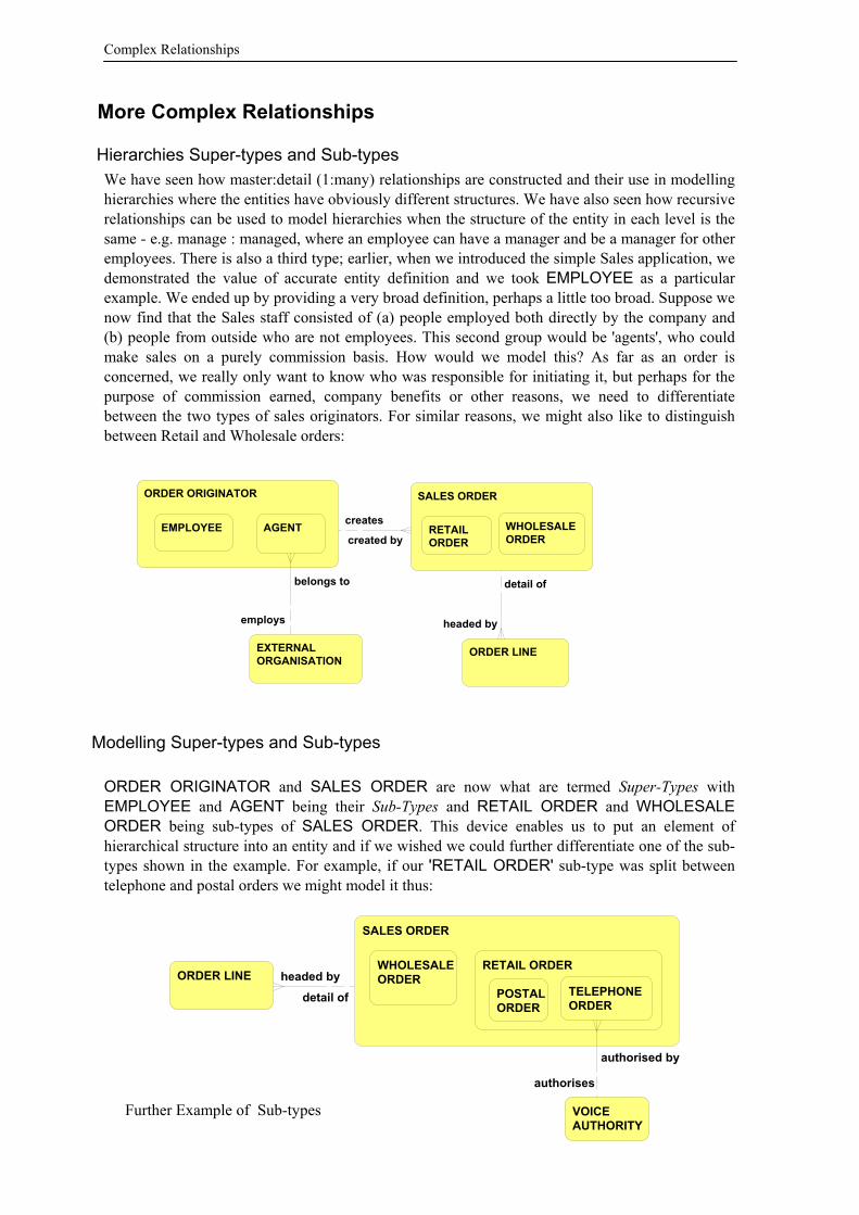
Complex Relationships
More Complex Relationships
Hierarchies Super-types and Sub-types We have seen how master:detail (1:many) relationships are constructed and their use in modelling hierarchies where the entities have obviously different structures. We have also seen how recursive relationships can be used to model hierarchies when the structure of the entity in each level is the same - e.g. manage : managed, where an employee can have a manager and be a manager for other employees. There is also a third type; earlier, when we introduced the simple Sales application, we demonstrated the value of accurate entity definition and we took EMPLOYEE as a particular example. We ended up by providing a very broad definition, perhaps a little too broad. Suppose we now find that the Sales staff consisted of (a) people employed both directly by the company and (b) people from outside who are not employees. This second group would be 'agents', who could make sales on a purely commission basis. How would we model this? As far as an order is concerned, we really only want to know who was responsible for initiating it, but perhaps for the purpose of commission earned, company benefits or other reasons, we need to differentiate between the two types of sales originators. For similar reasons, we might also like to distinguish between Retail and Wholesale orders:
Modelling Super-types and Sub-types ORDER ORIGINATOR and SALES ORDER are now what are termed Super-Types with EMPLOYEE and AGENT being their Sub-Types and RETAIL ORDER and WHOLESALE ORDER being sub-types of SALES ORDER. This device enables us to put an element of hierarchical structure into an entity and if we wished we could further differentiate one of the sub-types shown in the example. For example, if our 'RETAIL ORDER' sub-type was split between telephone and postal orders we might model it thus:
Further Example of Sub-types
EXTERNALORGANISATION
ORDER LINE
SALES ORDERORDER ORIGINATOR
WHOLESALEORDER
RETAILORDER
EMPLOYEE AGENT
belongs to
employs headed by
detail of
created by
creates
VOICEAUTHORITY
SALES ORDER
ORDER LINERETAIL ORDERWHOLESALE
ORDERTELEPHONEORDER
POSTALORDER
authorised by
authorises
headed by
detail of
Complex Relationships
This kind of construction is a very useful modelling device for dealing with entities which are functionally very similar but may differ slightly in some respect. For example, the order sub-type TELEPHONE ORDER may require voice identification attributes whereas POSTAL ORDER does not. Sub-types can also have their own relationships to other entities as is shown above for TELEPHONE and VOICE AUTHORITY. In all respects, super-type and sub-types are treated as discrete entities, and these types of relationships are to be recommended providing they are used properly and in the correct context. They are, however, sometimes abused and can lead to problems of implementation. Here are a few rules / guide-lines: · A super-type should always have at least two sub-types. If there is only one sub-type shown in a
super-type, question the existence of the structure - there should be at least one other, even if it is called 'OTHER'.
· Sub-types should differ from the super-type and from other sub-types by at least one attribute,
not just by a type indicator value. We would, for example, expect there to be some difference in data requirements between EMPLOYEE and AGENT within the ORDER ORIGINATOR super-type.
· A sub-type will, by default, 'inherit' its primary key from the primary key of the super-type.
However, it is possible for a separate primary key to be specified for a sub-type in which case the super-type PK becomes a candidate key.
· A sub-type also inherits the super-type's foreign keys but any relationships made directly
between a sub-type (as opposed to its super-type) and another entity will imply a local arrangement, which the super-type will not share. Any foreign keys carried by a sub-type are not logically enforced on the super-type.
· There is no limit to the number of levels of nesting of sub/super types. However, two to three
levels maximum will normally cover most structures that are likely to arise. · Relationships can be created between members of a super-type, to external entities and
recursively just like any other separate entity. However, a super-type /sub-type structure will, initially at least, be turned into a single physical table (at least in the first cut physical model) so some common sense needs to be applied when modelling the logical model.
· ALWAYS use super / sub-type hierarchies, where possible, in preference to 'exclusive arc'
relationships (which we will come to next). · Only use sub-types when there are genuine similarities between them. If the attribute content is
completely different, re-consider your model: maybe an Exclusive Arc is more appropriate. Note that in the Object Oriented world, sub-types are synonymous with the concept of ‘inheritance’.

Common Solutions
‘Complex’ Relationships: Arcs From the outset, we recommend that arc type (complex) relationships be avoided, if at all possible, because they create extra work and complexity in the physical model. They do have their place in the modelling repertoire and can be appropriate. Consider the following structure:
This structure tells us that a SALES ORDER is either connected to (made by) an AGENT OR an EMPLOYEE, i.e. AGENT and EMPLOYEE are mutually exclusive- they cannot be both at the same time. CUSTOMER does not appear in the arc and so is not part of a mutually exclusive set. There is no restriction in the number of relationships that are included in an exclusive arc and arcs may be nested to form even more complex relationships. Reading the relationships now becomes slightly more complicated in respect of the complex relationships, starting from SALES ORDER: "A SALES ORDER must originate from one and only one EMPLOYEE or one and only one AGENT."
Rules for Exclusive Arcs
Some Common Modelling Solutions Consider these models, having being advised of the rules and work out which ones are invalid structures:Resolving ‘many-to-many’ relationships: creating Intersections One of the most common problems that we come across is solving a many to many relationship in
C. D.
Answer: All of them are Invalid, they all break one rule or another!
AGENT
EMPLOYEE
SALES ORDER
A. B.
SALES ORDER
EMPLOYEE
AGENT CUSTOMER
placed by
places
placed by
places
placed by
places

Sub-Types & Super-Types
its various guises. The reader will perhaps have noticed that some entities can only exist between two (or more) other entities. For example, the ORDER Entity in our sales model can only exist when an EMPLOYEE takes details of an order for PARTS for a CUSTOMER. In our model, without an instance of one of these entities, an ORDER could not exist. For this reason, the ORDER entity is known as an Intersection or Associative entity. In this example, the ORDER has an identity and meaning of its own - an order is an order (as well as solving many products are ordered by many customers recorded by many sales staff) but, in other cases, an intersection entity can have no inherent meaning of its own. However, it has great importance as a device for solving many to many relationships. Here are some more examples: During his/her career, an employee may hold several positions within a company, or perform a number of different roles. Conversely, over time, a role may be performed by a number of employees. It may be possible for a single employee to perform several roles at the same time and for the same role to be performed by a number of employees. So how do we model this scenario? Initially, we might describe the relationship as:
But we need to resolve this many:many relationship and we do this by introducing an intersection entity:
The entity EMPLOYEE ROLE, which is now interposed between EMPLOYEE and ROLE resolves their many to many relationship. The very minimum for an intersection entity is a primary key comprising the two primary keys of the entities which it resolves. Its primary key, therefore, contains the foreign keys for EMPLOYEE and ROLE. Instances of EMPLOYEE ROLE can now allow a Staff No. to be associated with a Role. The primary key of this entity will consist of the two associated primary keys. This device will allow a Staff No. to be associated with many different Role Ids. or vice versa, thus enabling any combination of employee and role. The structure proposed above is still incomplete as it makes no provision for changes over time, i.e. we would expect employees to move from one role to another, perhaps even fulfil two or more roles at the same time. Note that Intersection tables often carry other attributes - such as the time dimension (see how this is achieved in Chapter 5: Advanced Entity Modelling ).
Key Point: Using intersection entities to resolve many:many relationships is an essentialtechnique for prising out further entities and relationships as well as a necessary techniquerequired for implementation.
Tip: Naming an Intersection Entity - If the intersection entity has some meaningful name(such as ORDER) then all well and good but if, as in the above example, there is no obviousname, by convention use a combination of the entities which it intersects, e.g. EMPLOYEEROLE. The identity and purpose of the entity then becomes obvious when reading the ERDor Data Dictionary.
# STAFF ID # ROLE ID
EMPLOYEEROLE
ROLE# ROLE ID
EMPLOYEE# STAFF ID
takes
taken byoccupied by
occupies
ROLEEMPLOYEEoccupied by
occupies

Modelling Hierarchies
© Domanski & Irvine 2000-2005 42
Topics dealt with in the rest of this chapter
Modelling a Hierarchy 1) Common attributes across types 2) Common attributes but at least one different 3) Few if any attributes shared: Mutually Exclusive Entities
Creating a Data Dictionary (DD) Using a CASE Tool? Not using a CASE Tool?
Requirements for each Entity: Requirements for each Attribute: Requirements for information across Entities and Attributes:
We hope that you have found this chapter useful. For those of you new to data modelling and database design there is a lot to take in BUT don’t be daunted. With a little practice you will find that it is not difficult – all you need is a pencil and piece of paper to start with. You can validate your models by following the advice given in this book and checking the ‘rules’ – of which there are relatively few To read the rest of this chapter, you will need to purchase a password to open the full .pdf file. Other parts of the book include the design-critical chapters on “Advanced Data Modeling” and “Getting Physical” which describes how to take your logical model to a physical database schema. Good Luck with your database designing!

GLOSSARY OF TERMS 3GL third generation languages e.g. COBOL, FORTRAN, ALGOL, PL/1, procedural high level languages, contrast with 2GL which are at a lower level i.e. closer to the instructions in a machine. 4GL fourth generation language. A language or application package that has a degree of automation to help the developer produce a product without the need to program in conventional languages (see 3GL). Examples are, Microsoft’s SQL*Server, Oracle 8i. etc. Application a set of screens, programs and reports which perform a specific set of tasks within a functional area of a business. Aim, Objective, Mission Statement a goal set by the owners of a business area, an aim is not a measurable goal, an objective is measurable and a mission statement is the set of principles in which aims and objectives are set. Attribute a unit of information – date, description, value, etc. A characteristic or element used to classify, identify, quantify or describe an Entity. Binary Tree the method database software uses to implement an index. Bottom-Up Approach a methodological approach through which a system is designed upwards from its functional components rather than originating from a strategic view from the top. See Top-Down Business Rules general rules within a business which must be applied with business functions e.g. salesman commission is paid on sales 10% greater than target. Business Unit a component part of a business oriented towards product lines, production units, services, departments and section, etc.. Business units can also be different sites, countries and other geographical units. Cascade Delete a delete which must be propagated to other tables in an application or database. e.g. deleting a department will also have to delete or transfer all employees of that department! There are also cascade updates where the update of a code must also be propagated. CASE (Computer Aided Systems Engineering) Analysis, Design and Development assisted by software tools. Usually based on a proprietary methodological approach. Particularly useful for large database projects requiring management of evolutionary change. Can be used exclusively to administer logical and physical models and/or create and maintain application design and generation. Client/Server Database System a design configuration where the application is separated into two parts; the Client Front End, User Interface usually a GUI; and a Server Back End (providing the data on request, usually a Database Server). The Client and Server processes usually run on separate machines and communicate over various protocol layers. Complex Relationship generally refers to ‘arcs’ in which there are alternative ‘master : detail’ relationships. Requires specific modelling techniques to minimise the application design complexity for administering these structures. Constraint a means of applying a rule within a database – facilitated by a proprietary RDBMS feature – E.g. the automatic application of a validation rule, prevention of loss of integrity by PK and FK relationships. Etc. Convergent Model a version of the data model that has been ‘tuned’ as a step to the creation of a compact physical database model. See Divergent Model CRM (Customer Relationship Management) An application pivoted on the customer. Generally difficult concept to maintain as ‘customer’ is a complex topic. Requires a hybrid OLAP / OLTP approach to system’s design. CSF (Critical Success Factors) something which, if not achieved, will put in jeopardy a business aim, objective or mission. Data Model a formalised, logical ‘blue-print’ of the information structure required to support a set of functional requirements. See ERD
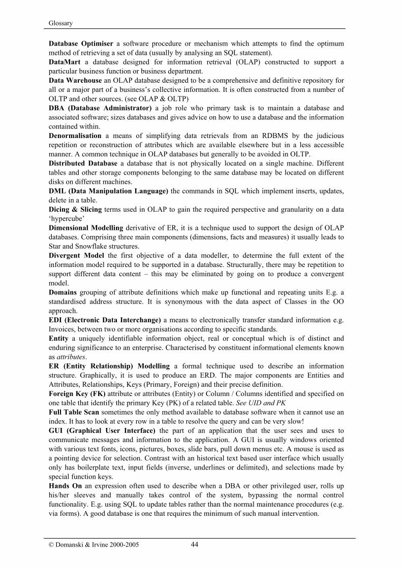
Glossary
© Domanski & Irvine 2000-2005 44
Database Optimiser a software procedure or mechanism which attempts to find the optimum method of retrieving a set of data (usually by analysing an SQL statement). DataMart a database designed for information retrieval (OLAP) constructed to support a particular business function or business department. Data Warehouse an OLAP database designed to be a comprehensive and definitive repository for all or a major part of a business’s collective information. It is often constructed from a number of OLTP and other sources. (see OLAP & OLTP) DBA (Database Administrator) a job role who primary task is to maintain a database and associated software; sizes databases and gives advice on how to use a database and the information contained within. Denormalisation a means of simplifying data retrievals from an RDBMS by the judicious repetition or reconstruction of attributes which are available elsewhere but in a less accessible manner. A common technique in OLAP databases but generally to be avoided in OLTP. Distributed Database a database that is not physically located on a single machine. Different tables and other storage components belonging to the same database may be located on different disks on different machines. DML (Data Manipulation Language) the commands in SQL which implement inserts, updates, delete in a table. Dicing & Slicing terms used in OLAP to gain the required perspective and granularity on a data ‘hypercube’ Dimensional Modelling derivative of ER, it is a technique used to support the design of OLAP databases. Comprising three main components (dimensions, facts and measures) it usually leads to Star and Snowflake structures. Divergent Model the first objective of a data modeller, to determine the full extent of the information model required to be supported in a database. Structurally, there may be repetition to support different data content – this may be eliminated by going on to produce a convergent model. Domains grouping of attribute definitions which make up functional and repeating units E.g. a standardised address structure. It is synonymous with the data aspect of Classes in the OO approach. EDI (Electronic Data Interchange) a means to electronically transfer standard information e.g. Invoices, between two or more organisations according to specific standards. Entity a uniquely identifiable information object, real or conceptual which is of distinct and enduring significance to an enterprise. Characterised by constituent informational elements known as attributes. ER (Entity Relationship) Modelling a formal technique used to describe an information structure. Graphically, it is used to produce an ERD. The major components are Entities and Attributes, Relationships, Keys (Primary, Foreign) and their precise definition. Foreign Key (FK) attribute or attributes (Entity) or Column / Columns identified and specified on one table that identify the primary Key (PK) of a related table. See UID and PK Full Table Scan sometimes the only method available to database software when it cannot use an index. It has to look at every row in a table to resolve the query and can be very slow! GUI (Graphical User Interface) the part of an application that the user sees and uses to communicate messages and information to the application. A GUI is usually windows oriented with various text fonts, icons, pictures, boxes, slide bars, pull down menus etc. A mouse is used as a pointing device for selection. Contrast with an historical text based user interface which usually only has boilerplate text, input fields (inverse, underlines or delimited), and selections made by special function keys. Hands On an expression often used to describe when a DBA or other privileged user, rolls up his/her sleeves and manually takes control of the system, bypassing the normal control functionality. E.g. using SQL to update tables rather than the normal maintenance procedures (e.g. via forms). A good database is one that requires the minimum of such manual intervention.

Glossary
Hypercube a conceptual view of a multi-dimensional structure often used by OLAP tools. See Dimensional Modelling. Index like the index of a book, an index provides the means of looking up the precise location of a table row. The correct application of an index may speed up retrieval a thousand-fold. A table may have multiple indexes. Indexes are supported by various mechanisms, the most common in current use is the Binary Tree. Integrity (referential integrity) a state in which all the database tables are in perfect synchrony, i.e. all foreign keys point to the right primary keys, there being no key records missing or extra. Loss of integrity can occur if records are deleted or inserted without proper regard to their relationships with other tables. Intersection Entity/Table a entity/table positioned between two entities used to solve their many:many relationship. In its simplest form it carries only their PKs. However, can be more complex, holding time and/or other value information. JAD (Joint Application Development) a methodology suitable for applications where there is a close and effective relationship with the ‘Client’. Often associated with RAD. KPI (Key Performance Indicator) criterion or statistic on how an organisation or project is judged, monitored and controlled. e.g. share price, profitability, cash flow, return on capital measurement against expected result, etc. Legacy System a system already operational in the organisation and covering a similar functional area to the proposed new system. Contrast with a green field site where the system will be completely new apart from manual procedures. A heritage system is a legacy system which could be placed in a museum! There may be many good reasons why a legacy system should remain – e.g. the sheer cost of replacing the functionality it supports – such as interfaces to OLAP systems. Estimating the cost of developing a replacement system often overlooks such cross-system functionality! Logical Model an idealised model of requirements. It is usually free from the constraints and contortions imposed by the technology used to create the Physical Model. Metadata information held about the location and configuration of data structures (as opposed to actual data). Commonly used at the heart of OLAP tools. Model a coordinated view and means of representing the business that an application must satisfy. Usually the model is represented in diagrammatic form but can also be in words. Normalisation the process used to reduce the data model to its simplest, minimalist form in which an attribute only occurs once. A good data model is usually in what is termed Third Normal Form (3NF). Deliberately repeating an attributes/columns in other entities/tables is called denormalisation. Object Orientation a development paradigm where everything is considered an object (even procedures). Consists of OOA (Object Oriented Analysis), OOD (Object Oriented Design) and OOP (Object Oriented Programming). OLAP Database (On-line Analysis Processing) is oriented towards data analysis and information extraction, it is usually read-only. Architypically, Data Warehouses and Marts are OLAP. Modelling usually uses the dimensional approach. Surrounded by a rich and expanding terminology – Eg. Variants ROLAP, MOLAP, HOLAP. OLAP Tools A fast growing and wealthy corner of the database market. OLAP tools are used to analyse / extract / present information from databases which may be OLAP or OLTP in nature. The best represent database structures as metadata upon which hypercube / dicing & slicing techniques can be applied. OLTP Database (On-Line Transaction Processing). General ‘workhorse’ database used primarily to store and maintain transactions in all their guises. Not generally orientated to data analysis and extraction and so may be very inefficient for these purposes. Generally mirrors the normalised information model. Where intensive analysis required (in read-only mode) designers may resort to OLAP tools or even wholesale design of derivative OLAP database. See OLAP & Data Warehouse. Outer Join an SQL construct which allows a table join to a table where the foreign key is null.

Glossary
© Domanski & Irvine 2000-2005 46
Pigs Ear not, as commonly thought, a negative descriptive term applied to project deliverables (c.f. ‘A dog’s Breakfast’) but a term used for a recursive relationship. E.g. The manage / managed relationship from an EMPLOYEE to itself – forms tree-lik structures. Physical Model the end result – the physical manifestation of an actual database. Usually (but not necessarily) very similar to logical model but adapted to overcome / take advantage of the software features of an RDBMS tool. Primary Key (PK) Attribute or attributes (Entity) or Column / columns (Table) specifically identified and specified as forming the UID. See Integrity Project a set of tasks and activities oriented towards building one or more applications. Prototype A delivery step used in RAD/JAD to demonstrate project progress and an understanding of the clients’ requirements. A mixed blessing as can often be a serious distraction to development. Never, unless under extreme conditions (emergency) implement prototypes. RAD (Rapid Application Development) a methodology suitable for applications where speed of development is paramount. See JAD RDBMS Relational Database Management System – utilise the relational concept but generally includes a host of features to create an application. Relationship a formal description of association between two entities An EMPLOYEE “must be employed by a single” DEPARTMENT. The relationship, though is usually asymmetric as A DEPARTMENT “may employ many” EMPLOYEES. Relationships are described by a number of characteristics: Optionality, Description and Cardinality. SQL (Structured Query Language) a standard language used to interface with a relational database, with English-like statements. Stored Procedure programmable code such as SQL stored within the database that can be invoked by triggers or called by application components System Id a commonly used term to describe a Unique System Identifier based upon an incrementing sequence number or code (see artificial primary keys). Top Down Approach a methodological approach where analysis and design is based upon a strategic view downwards from the Business, may result in wholesale redesign of functions and processes. Tree Walking the process of scanning a tree-style structure in hierarchical way. It is implemented in some proprietary versions of SQL (but not in all). Trigger a specific event such as a database insert, update or delete which initiates a related or consequential procedure. May automatically invoke a stored procedure. UID (Unique Identifier) an attribute or combination of attributes enabling a specific instance to be uniquely and unambiguously identified. Synonymous with the Primary Key (PK). UML (Universal Modelling Language) an OO-based mooted standard similar in nature to ER and the RDBMS Enterprise approach. View a predetermined 'window' based on a table or series of tables. A view can be programmed to show different information to different users. A view can be used just as a normal table in most respects other than for DML operations.

Index Address structure, 39 Advanced Connection Traps, 93 Advanced Sub-Types, 90. See sub-types and
super-types Alternative Key (CK), 45 Analysis
detailed, 69, 75 Arcs
arc vs. sub-types, 100 designing out, 89, 91 rules for, 54
Artificial Key, 42 Attributes
common across type, 56 concatenated, 98 denormalised, 38 formats, 35 guide-lines, 37 naming conventions, 35 optionality, 36 Overlapping Data, 98 separating / combining components, 102 sub-types & super-types, 56
Audit Trails, 84 for database security, 152
BOM Structure, 83 Build Phase, 72 Business case study, 163
interview technique, 164 summary of detailed analysis, 171
Business Rules definitions, 48
Candidate Keys (CK) definition, 12
Cardinality, 47 CASE
advantages, 147 use of, 145
CASE Tools, 58 Chasm Trap, 92 Codes & reference tables, 114 Columns
introduction, 10 Concatenated or Composite Key, 42 Convergent vs. Divergent Data Model, 86 Cost Benefit Analysis, 75 CRM, 144 Customer principle, 139 Data Access
introduction, 8 Data cloud principle, 141 Data Dictionary
creating one, 57 defintion, 30
Data driven approach, 114 Data Modelling
component definition, 29 introduction, 27
Data range and validation, 36
Data warehouses data mining, 132 data quality, 133 design techniques, 130 dicing and slicing, 132 drill-down & roll-up, 132 granularity, 131 population, 134 terminology, 130 what are they?, 130
Database Security, 149 avoiding data destruction, 152 avoiding misuse, 153 human error, 150 integrity loss, 151
Datamarts, 130 Delete vs. archive, 102 Deliverables, 66
definition, 74 Denormalisation, 94
relationships, 95 risks of, 152
Denormalising dangers, 113
Design, 70 phases, 67 sub-types and super-types, 100
Design considerations checklist, 126 legacy systems, 121 structured codes, 122
DFD, 17, 18, 23 components, 24 strengths and weaknesses, 25
Dimensional modelling, 131 Doctor
Patient relationship, 31 Domains
definition, 39 use of, 40
Enterprise Model, 17 case for, 18 scope of, 17
Entities generic vs. specific, 101 grouping, 85 identifying, 31 intersection, 81
Entity examples, 30 naming conventions, 34
Entity Modelling advanced, 81
ERD, 17, 18, 28 hand drawing, 32 simple case, 32
Fan Trap, 92 FDD, 17, 18, 20
benefits of, 20

Index
© Domanski & Irvine 2000-2005 48
building one, 22 Field Overloading, 97 Foreign Key (FK), 45
definition, 12 Fringe Tables, 96 Functions, 20
identifying, 22 Hierarchies
modelling, 56 super-types and sub-types, 52
Historical Data retaining, 83
Housekeeping, 9 Implementation Phase, 72 Indexes
composite, 118 creating, 117 downside, 119 implementation of, 118 primary keys, 117 when to use them, 118
Information Gathering, 77 Intersection Entities and Time, 81 Legacy Structures, 97 Life Cycle Methodology, 60
types, 61 Look-up Lists, 36 Menus
introduction, 9 Milestones, 65 Modelling
avoiding pitfalls, 92 common solutions, 55 complicated splits, 99 design dilemmas, 100 exceptions, 71, 98 introduction, 19 overlapping models, 18 super-types and sub-types, 52
Normal Forms, 41 Normalisation
principles, 41 Null vs. not nill columns, 102 OLAP, 127
selecting a solution, 135 tools, 128 transformation, 129 vs. OLTP, 127
Optionality, 47 Organisations
features, 141 People and organisations, 139 Physical Model 1
1 mapping with ERD, 108 column naming, 106 dealing with sub-types, 108 differences from ERD, 106 divergence from logical model, 108, 112 implementing arcs, 110 prerequisites, 105 table naming, 106
Pigs Ears, 82 Primary Key
role of in modelling, 41 Primary Key (PK), 11
advice on selection, 44 artificial, 43 choosing, 11 representing on the ERD, 43 types of, 42
Primary Key (PK)., 11 Processes, 21
elemental, 21 Production Phase, 73 Project Plan, 64 Project Planning, 59 Proprietary RDBMS features, 124
constraints, 124 stored procedures and triggers, 124
Prototyping, 156 Quality Checking
CRUD matrix, 155 design checklist, 159 peer review, 156 reviewing physical model, 157
Queries graphical, 15
Queries and Reports introduction, 7
RDBMS engine, 6 Environment, 6 history, 2 introduction, 10
Relationships complex, arcs, 54 definition, 46 modelling, 31, 49 naming, 47 recursive, 50, 82
Rows introduction, 10
Sales Order model, 33 Screen Example, 182 Snapshots, 117 Splitting tables, 113 Spreadsheet
as a table, 10 SQL
joining tables, 13 what is it?, 6
Star schemas, 131 Star Schemas, 131 Strategy, 68 Table
example, 10 introduction, 10 relationships, 12 Vehicles example, 11
UIDs, 41 Views, 116
END OF BOOK SAMPLE