A Practical Guide to Computer Network & Internet...
65
2015 Babu Ram Dawadi Institute of Engineering, Pulchowk Campus, Tribhuvan University A Practical Guide to Computer Network & Internet Technologies
Transcript of A Practical Guide to Computer Network & Internet...
2015
Babu Ram Dawadi
Institute of Engineering,
Pulchowk Campus,
Tribhuvan University
A Practical Guide to Computer Network & Internet Technologies

Network Lab Manual: Babu Ram Dawadi
Page 1 of 64
Preface
Networking is a big domain under computer science and engineering. There are several streams
and area of specializations under computer network in which students shall have their own
choices for their future career. The course contents of computer network under bachelor degree
level is very basics. It simply provides the overall theoretical knowledge on communication
standards, protocols and network programming. Students have to learn about lots of new terms
and technologies in computer network making this a bit hard to grab the knowledge the sufficient
knowledge on computer. Hence, sufficient practical activities and tutorial practices are required
under this subject to verify the concepts and strengthen the practical knowledge that shall be
directly implemented in the real industries after graduation.
This lab manual on computer network is an attempt of my twelve+ years of experiences in
teaching this subject. It helps course instructor for smooth lesson planning of his/her teaching
and students to have more clarification on the theoretical knowledge achieved during the class
hours. Students are instructed to do the lab tutorial step by step as an example first and then do
given task after getting the practical concepts on each lab. This reduces the confusion for both
instructor and students about what to do next in the lab.
There are fourteen lab sheets including case study and final exam designed to be completed
within the specified academic period (one semester course) starting from the basic concepts of
network hardware/software to advance level configuration up to routing, security implementation
and different server systems deployment. I tried to cover the new networking technologies, tools,
software/hardware on every lab with the objectives to provide sufficient latest knowledge on
computer network to my valued readers. Students have to complete the tutorial steps during the
lab hours and submit the task and exercise work on the next lab.
I would like to request all the instructors, students and well-wishers to have feedback/comments
at [email protected] or via www.baburd.com.np about this manual that would definitely help
me out to come up with the best manual further with new versions in the future.
Thank you!
Babu Ram Dawadi
Asst. Professor, IOE Pulchowk Campus, Tribhuvan University
Network Lab Manual: Babu Ram Dawadi
Page 2 of 64
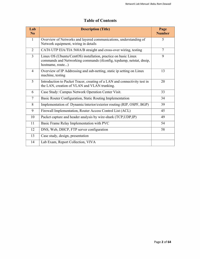
Table of Contents
Lab No
Description (Title) Page Number
1 Overview of Networks and layered communications, understanding of Network equipment, wiring in details
5
2 CAT6 UTP EIA/TIA 568A/B straight and cross-over wiring, testing 7
3 Linux OS (Ubuntu/CentOS) installation, practice on basic Linux commands and Networking commands (ifconfig, tcpdump, netstat, dnsip, hostname, route...)
9
4 Overview of IP Addressing and sub-netting, static ip setting on Linux machine, testing
13
5 Introduction to Packet Tracer, creating of a LAN and connectivity test in the LAN, creation of VLAN and VLAN trunking.
20
6 Case Study: Campus Network Operation Center Visit. 33
7 Basic Router Configuration, Static Routing Implementation 34
8 Implementation of Dynamic/interior/exterior routing (RIP, OSPF, BGP) 39
9 Firewall Implementation, Router Access Control List (ACL) 45
10 Packet capture and header analysis by wire-shark (TCP,UDP,IP) 49
11 Basic Frame Relay Implementation with PVC 54
12 DNS, Web, DHCP, FTP server configuration 58
13 Case study, design, presentation
14 Lab Exam, Report Collection, VIVA

Network Lab Manual: Babu Ram Dawadi
Page 3 of 64
Computer Network Lab
Lab Marks Distribution
Lab Reports Attendance/Viva Final Exam Total Full Marks 40% 20% 40% 100%
Overall Objective:
The lab works in this course provides hands on training and knowledge about the analysis, design, troubleshooting, modeling, testing and evaluation of computer networks. Students shall have access to real test-bed networks, virtual and simulated network with the tools like tcpdump, wireshark, ip scanner, packet tracer, opnet, mininet, visio, Bosom, NetSim etc.. to fulfill the objectives set forth on each lab. At the end, student shall be able to perform the network and server administration like addressing management, switching (VLAN, VTP), routing and remote administration (SSH, Telnet, Hyperterminal), TCU/UDP/IP packet analysis, configuring of web, dns, dhcp and ftp servers over linux/unix OS. Students will gain the opportunity to design and develop networking model, simulation and testing with sufficient security measures.
For Students:
Students have to complete at least 10 to 12 lab activities throughout the semester to fulfill the objectives of the course Computer Network at Bachelor of engineering and computer science. Each lab manual is designed with lab objective, basic theoretical background, and sample example with necessary steps to operate with the networking tools and exercise. Before appearing into the lab, all are requested to learn the relevant activities in summary and explore theory/practical concepts of corresponding lab. Students have to do the exercise provided and submit the report into the next lab. Lab report to be submitted should include at least the following topics.
1. Cover page
2. Title
3. Objective(s)
4. Apparatus
5. Procedure (steps), (Explanation, topology if any, setup, configuration)
6. Testing and verification (if any)
7. Discussion and Conclusion

Network Lab Manual: Babu Ram Dawadi
Page 4 of 64
LAB 1
Lab No Description (Title)
1 Overview of Networks and layered communications, understanding of Network equipment, wiring in details
2 CAT6 UTP EIA/TIA 568A/B straight and cross-over wiring, testing
Objective(s):
To understand layered communications and protocols
To feel and know the networking equipment (repeater, hub, bridge, switch, router, crimper, UTP, Fiber cable, connectors, patch panel, cable managers, racks, CAT6 straight and crossover wiring standards, LAN meter/tester, RJ-45)
Network Hardware: Crimper/clamper, RJ-45 jack male/female, LAN/Cable tester, UTP, Fiber cable, HUB/Switch/Router/Bridge, patch panel, cable manager....
Repeaters are simple devices that work at the physical layer of the OSI. They regenerate signals (active hubs does that too).
Hubs are used to build a LAN by connecting different computers in a star/hierarchal network topology, the most common type on LANs now a day. A hub is a very simple (or dumb) device, once it gets bits of data sent from computer A to B, it does not check the destination, instead, it forwards that signal to all other computers (B, C, D…) within the network. B will then pick it up while other nodes discard it. This amplify that the traffic is shared.
There are mainly two types of hubs:
1. Passive: The signal is forwarded as it is (so it doesn’t need power supply). 2. Active: The signal is amplified, so they work as repeaters. In fact they have been called multiport repeaters. Hub is a multiport repeater.
Hubs can be connected to other hubs using an uplink port to extend the network. Hubs work on the physical layer (lowest layer). That’s the reason they can’t deal with addressing or data filtering.
Switches on the other hand are more advanced. Instead of broadcasting the frames everywhere, a switch actually checks for the destination MAC address and forwards it to the relevant port to reach that computer only. This way, switches reduce traffic and divide the collision domain into segments, this is very sufficient for busy LANs and it also protects frames from being sniffed by other computers sharing the same segment.
They build a table of which MAC address belongs to which segment. If a destination MAC address is not in the table it forwards to all segments except the source segment. If the destination is same as the source, frame is discarded.
Switches have built-in hardware chips solely designed to perform switching capabilities, therefore they are fast and come with many ports. Sometimes they are referred to as intelligent bridges or multiport bridges.
Most common switching methods are: 1. Cut-through: Directly forward what the switch gets. 2. Store and forward: receive the full frame before retransmitting it.
Normal Switches are on the data link layer (just above physical layer), that’s why they deal with frames instead of bits and filter them based on MAC addresses. Switches are known to be used for their filtering capabilities. Intelligent switches works as a router.
VLANs (Virtual LANs) and broadcast domains: Switches do not control broadcast domains by default, however, if a VLAN is configured in a switch it shall have its own broadcast domain.
VLAN is a logical group of network devices located on different LAN physical segments. However they are logically treated as if they were located on a single segment.
Bridges are used to extend networks by maintaining signals and traffic. Bridges are on the data link layer so in principle they are capable to do what switches do like data filtering and separating the collision domain, but they are less advanced. They are known to be used to extend distance capabilities of networks.

Network Lab Manual: Babu Ram Dawadi
Page 5 of 64
In a comparison with switches, bridges are slower because they use software to perform switching. They do not control broadcast domains and usually come with less number of ports. Multiport bridges are generally termed as switch.
Routers are used to connect different LANs or a LAN with a WAN (e.g. the internet). Routers control both collision domains and broadcast domains. If the packet’s destination is on a different network, a router is used to pass it the right way, so without routers, the internet could not functions. Routers use NAT (Network Address Translation) in conjunction with IP Masquerading to provide the internet to multiple nodes in the LAN under a single IP address. Routers work on the network layer so they can filter data based on IP addresses. They have routing tables to store network addresses and forward packets to the right port.
Gateways are very intelligent devices or else can be a computer running the appropriate software to connect and translate data between networks with different protocols or architecture, so their work is much more complex than a normal router. For instance, allowing communication between TCP/IP clients and IPX/SPX or AppleTalk. Gateways operate at the network layer and above, but most of them at the application layer.
There is an important rule to obey while using repeaters/hubs to extend a local network and is called the 5-4-3. The rule forces that in a single collision domain there shouldn’t be more than 5 segments, 4 repeaters between any two hosts in the network and only 3 of the segments can be populated (contain user connections). This rule ensures that a signal sent over the network will reach every part of it within an acceptable length of time. If the network is bigger, the collision domain can be divided into two parts or more using a switch or a bridge.
Exercise:
1. What are physical layer devices? 2. What are the differences between Repeater and Hub? Hub and Switch?, Bridge and Switch?, Switch and
Router? 3. What is virtual LAN? Why do we need to create VLAN? 4. Discuss Different Network Topologies

Network Lab Manual: Babu Ram Dawadi
Page 6 of 64
LAB 2
Lab No Description (Title)
1 Overview of Networks and layered communications, understanding of Network equipment, wiring in details
2 CAT6 UTP EIA/TIA 568A/B straight and cross-over wiring, testing.
3 Linux OS (Ubuntu/CentOS) installation, practice on basic Linux commands and Networking commands (ifconfig, tcpdump, netstat, dnsip, hostname, route...)
Objective(s): To understand the color coding standard of UTP cable To create straight and crossover cable and test/verify its connectivity.
Apparatus: UTP CAT6 cable (1M), Crimper, LAN tester
Background: RJ-45 connectors intended for use with CAT-6 cable are larger than their CAT-5 counterparts. Begin by stripping the outer covering from the end of the cable. Remove about an inch of covering. Eventually you'll have to cut down the amount of exposed cable, but the process of installing the RJ-45 connector will be easier if you have plenty of exposed cable to work with (but not too much). Once you remove the outer cover, you'll see that some of the pairs of wire are twisted together (hence the name twisted-pair cable). Untwist these wires. Once all the wires have been separated, pull them backward so you can cut off the exposed plastic core, as shown below. Remove
as much of this core as you can. Be careful not to accidentally cut the wires in the process.
Now that the core has been removed, your next task is to straighten the wires that were previously twisted. The easiest way to do this is by using two pairs of tweezers. Use one set of tweezers to firmly hold the wire just beneath a bend, and the other pair to straighten the bend. The wires don't have to be perfectly straight, but the straighter they are, the easier your job will be. Once you've
straightened the wires, your next task is to arrange them in the order they'll be placed into the RJ-45 connector. Working from left to right, the order of the wires shall be set with EIA 568 A or B standard as follows:
568 B standards (wiring sequence) 568 A standards (wiring sequence)
Partial Orange (Orange with white stripe), Solid Orange, Partial Green, Solid Blue, Partial Blue, Solid Green, Partial Brown, Solid Brown
Partial Green (Green with white stripe), Solid Green, Partial Orange, Solid Blue, Partial Blue, Solid Orange, Partial Brown, Solid Brown
Remember for normal wiring:
Odd Number Always holds the partial color while even number holds the solid color.
Only 1-3, 2-6 pair of number required to be adjust for A and B standard. Orange and Green are
interchangeable.
Color code for number 4, 5, 7 & 8 are always fixed.
Standard A starts with Green and Standard B starts with Orange.

Network Lab Manual: Babu Ram Dawadi
Page 7 of 64
Let's start wiring by B standard. Since the leftmost wire is the orange with the white stripe, there's a natural tendency to start with this wire on the left. Although it's possible to get the wires in the correct order using this technique, getting the wires to stay in order when you insert the RJ-45 connector becomes very difficult. Rather than starting with the orange and white wire, lining up the wires is a lot easier if you start with the green wire with the white stripe, and then work on lining up the blue, partial blue, and green wires. When all is said and done, the wires will still have to be in the correct order, but starting with the partial green wire forces you to turn the cable a different direction than if you were initially working with the partial orange. This seems to make all the difference in the world for getting the wires lined up in a way that facilitates easy installation of the RJ-45 connector.
Now that the wires are in the correct order, hold the RJ-45 connector next to the cable, as shown below, to determine how much wire needs to be cut off, as shown below. You'll want to make the cut so that the ends of the wires line up evenly. The proper length can be determined by looking at the cable's outer insulation. The insulation should stop just inside of the RJ-45 connector. It's better to make a series of small cuts to determine the appropriate cable length than to try to get it exactly right on the first cut. Test-fit the RJ-45 connector between each cut. If you try to get the length exactly right on the first cut, you risk cutting the wires too short.
The easiest way to slide the RJ-45 connector onto the cable is to use your thumb to apply pressure to the cable in the spot where the wires are first exposed from beneath the insulation. This will help keep the wires in order. When the cable is finally cut to the correct length, you should check a few things before crimping the cable. First, make sure the wires go all the way to the end of the RJ-45 connector. The easiest way to do this is to look at the end of the connector and make sure you see copper in each wire slot. You
should also verify that the wires are still in the correct order. It's easy for the wires to get out of order when installing the cable end. A quick check at this point will keep you from having to cut the cable end off and starting over later. Assuming the wires are in order, you can go ahead and crimp the cable. When you've finished crimping both cable ends, you can use a cable tester to verify that the ends were installed correctly.
Your Task:
Using one meter CAT6 cable develop either cross-over or a straight cable, test and verify it.
Exercise:
1. Discuss the straight and crossover wiring standards.
2. Discuss RJ45 clamping procedure.
3. Where can we use straight, crossover and rollover cable? Explain.
4. Discuss different 802.3 Ethernet cable standards
Network Lab Manual: Babu Ram Dawadi
Page 8 of 64
LAB 3
Lab No Description (Title)
2 CAT6 UTP EIA/TIA 568A/B straight and cross-over wiring, testing
3 Linux OS (Ubuntu/CentOS) installation, practice on basic Linux commands and Networking commands (Ifconfig, tcpdump, netstat, dnsip, hostname, route...)
4 Overview of IP Addressing and sub-netting, static ip setting on linux machine, testing
Objective(s):
To understand basic command line operation with Linux operating system and network configuration, testing and verification.
Apparatus: Oracle virtual box, or VMware Workstation, Ubuntu or CentOS disk images
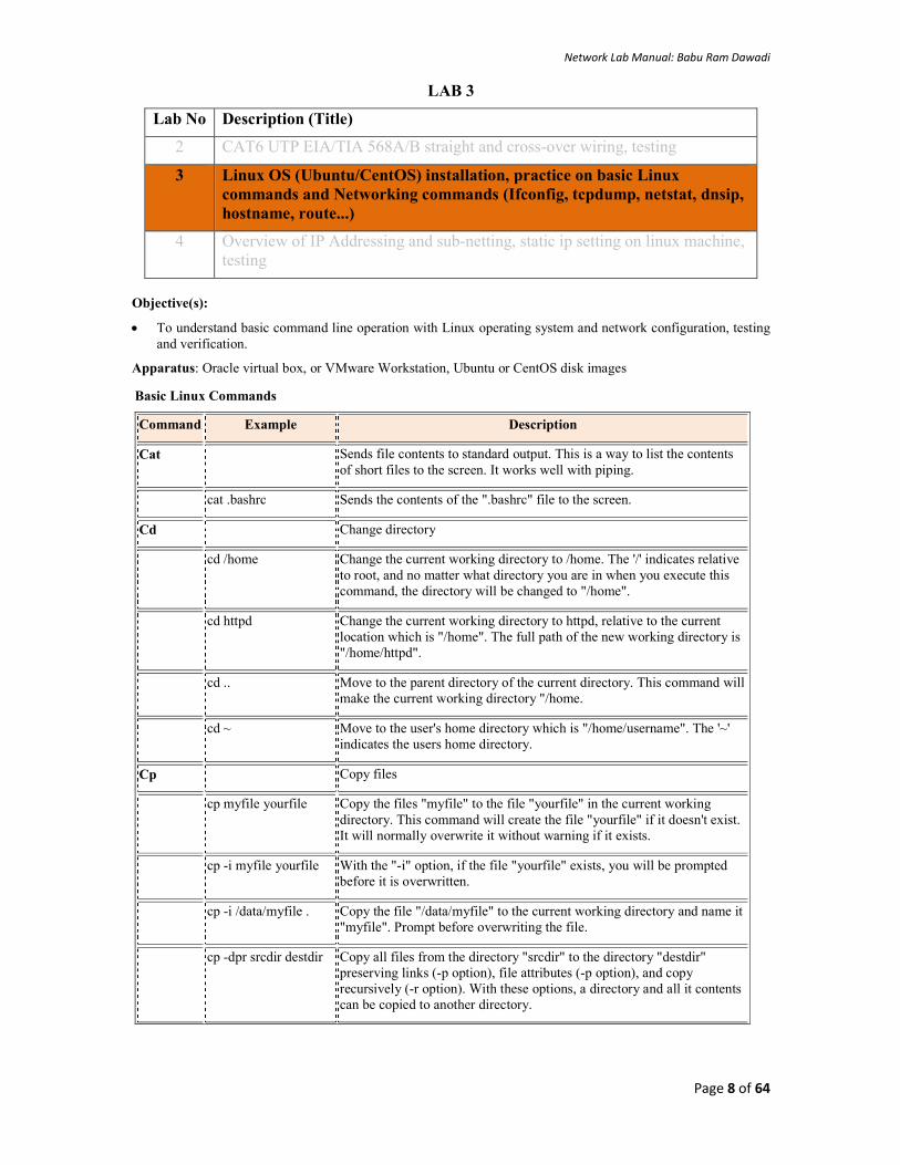
Basic Linux Commands
Command Example Description
Cat
Sends file contents to standard output. This is a way to list the contents of short files to the screen. It works well with piping.
cat .bashrc Sends the contents of the ".bashrc" file to the screen.
Cd Change directory
cd /home Change the current working directory to /home. The '/' indicates relative
to root, and no matter what directory you are in when you execute this command, the directory will be changed to "/home".
cd httpd Change the current working directory to httpd, relative to the current
location which is "/home". The full path of the new working directory is "/home/httpd".
cd .. Move to the parent directory of the current directory. This command will
make the current working directory "/home.
cd ~ Move to the user's home directory which is "/home/username". The '~'
indicates the users home directory.
Cp Copy files
cp myfile yourfile Copy the files "myfile" to the file "yourfile" in the current working
directory. This command will create the file "yourfile" if it doesn't exist. It will normally overwrite it without warning if it exists.
cp -i myfile yourfile With the "-i" option, if the file "yourfile" exists, you will be prompted
before it is overwritten.
cp -i /data/myfile . Copy the file "/data/myfile" to the current working directory and name it
"myfile". Prompt before overwriting the file.
cp -dpr srcdir destdir Copy all files from the directory "srcdir" to the directory "destdir" preserving links (-p option), file attributes (-p option), and copy recursively (-r option). With these options, a directory and all it contents can be copied to another directory.
Network Lab Manual: Babu Ram Dawadi
Page 9 of 64
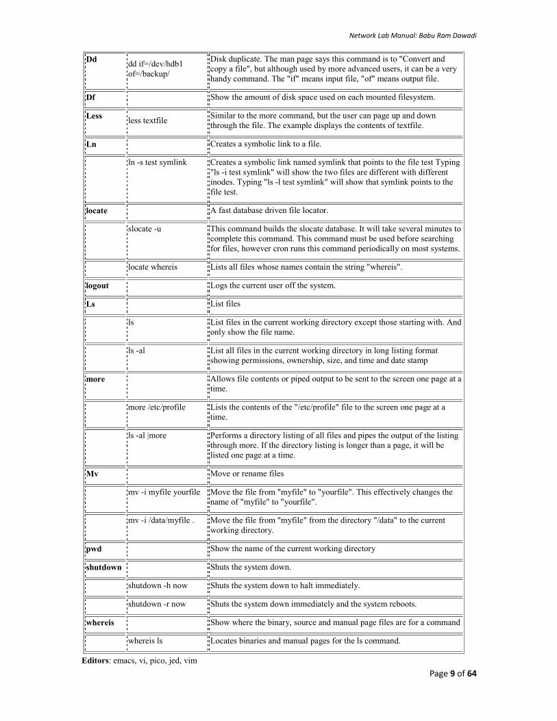
Dd dd if=/dev/hdb1 of=/backup/
Disk duplicate. The man page says this command is to "Convert and copy a file", but although used by more advanced users, it can be a very handy command. The "if" means input file, "of" means output file.
Df Show the amount of disk space used on each mounted filesystem.
Less less textfile
Similar to the more command, but the user can page up and down through the file. The example displays the contents of textfile.
Ln Creates a symbolic link to a file.
ln -s test symlink Creates a symbolic link named symlink that points to the file test Typing "ls -i test symlink" will show the two files are different with different inodes. Typing "ls -l test symlink" will show that symlink points to the file test.
locate A fast database driven file locator.
slocate -u This command builds the slocate database. It will take several minutes to
complete this command. This command must be used before searching for files, however cron runs this command periodically on most systems.
locate whereis Lists all files whose names contain the string "whereis".
logout Logs the current user off the system.
Ls List files
ls List files in the current working directory except those starting with. And
only show the file name.
ls -al List all files in the current working directory in long listing format
showing permissions, ownership, size, and time and date stamp
more
Allows file contents or piped output to be sent to the screen one page at a time.
more /etc/profile Lists the contents of the "/etc/profile" file to the screen one page at a
time.
ls -al |more Performs a directory listing of all files and pipes the output of the listing
through more. If the directory listing is longer than a page, it will be listed one page at a time.
Mv Move or rename files
mv -i myfile yourfile Move the file from "myfile" to "yourfile". This effectively changes the
name of "myfile" to "yourfile".
mv -i /data/myfile . Move the file from "myfile" from the directory "/data" to the current
working directory.
pwd Show the name of the current working directory
shutdown Shuts the system down.
shutdown -h now Shuts the system down to halt immediately.
shutdown -r now Shuts the system down immediately and the system reboots.
whereis Show where the binary, source and manual page files are for a command
whereis ls Locates binaries and manual pages for the ls command.
Editors: emacs, vi, pico, jed, vim

Network Lab Manual: Babu Ram Dawadi
Page 10 of 64
To Start vi
To use vi on a file, type in vi filename. If the file named exists, then the first page (or screen) of the file will be displayed; if the file does not exist, then an empty file and screen are created into which you may enter text.
* vi filename edit filename starting at line 1
vi -r filename recover filename that was being edited when system crashed
To Exit vi
Usually the new or modified file is saved when you leave vi. However, it is also possible to quit vi without saving the file.
Note: The cursor moves to bottom of screen whenever a colon (:) is typed. This type of command is completed by hitting the <Return> (or <Enter>) key.
* :x<Return> quit vi, writing out modified file to file named in original invocation
:wq<Return> quit vi, writing out modified file to file named in original invocation
:q<Return> quit (or exit) vi
* :q!<Return> quit vi even though latest changes have not been saved for this vi call
Adding, Changing, and Deleting Text
Unlike PC editors, you cannot replace or delete text by highlighting it with the mouse. The main purpose of an editor is to create, add, or modify text for a file.
Inserting or Adding Text
The following commands allow you to insert and add text. Each of these commands puts the vi editor into insert mode; thus, the <Esc> key must be pressed to terminate the entry of text and to put the vi editor back into command mode.
* i insert text before cursor, until <Esc> hit
I insert text at beginning of current line, until <Esc> hit
* a append text after cursor, until <Esc> hit
A append text to end of current line, until <Esc> hit
* o open and put text in a new line below current line, until <Esc> hit
* O open and put text in a new line above current line, until <Esc> hit
Changing Text
The following commands allow you to modify text.
* r replace single character under cursor (no <Esc> needed)
R replace characters, starting with current cursor position, until <Esc> hit
cw change the current word with new text, starting with the character under cursor, until <Esc> hit
cNw change N words beginning with character under cursor, until <Esc> hit; e.g., c5w changes 5 words
C change (replace) the characters in the current line, until <Esc> hit
cc change (replace) the entire current line, stopping when <Esc> is hit
Ncc or cNc change (replace) the next N lines, starting with the current line, stopping when <Esc> is hit

Network Lab Manual: Babu Ram Dawadi
Page 11 of 64
Deleting Text
The following commands allow you to delete text.
* x delete single character under cursor
Nx delete N characters, starting with character under cursor
dw delete the single word beginning with character under cursor
dNw delete N words beginning with character under cursor; e.g., d5w deletes 5 words
D delete the remainder of the line, starting with current cursor position
* dd delete entire current line
Ndd or dNd delete N lines, beginning with the current line; e.g., 5dd deletes 5 lines
Cutting and Pasting Text
The following commands allow you to copy and paste text.
yy copy (yank, cut) the current line into the buffer
Nyy or yNy copy (yank, cut) the next N lines, including the current line, into the buffer
p put (paste) the line(s) in the buffer into the text after the current line
Your Tasks:
Diagnose the output of the following network related commands in linux/ubuntu
#sudo ifconfig
#sudo ifdown eth0
#ifconfig eth0
#sudo ifup eth0
#man tcpdump //see manual information of tcpdump
#tcpdump -npi eth0
#netstat -ant
#dnsip
#hostname
#ping ip or hostname
#traceroute hostname or IP
#man route //see route command manual
#finger
#nslookup www.ioe.edu.np
Exercise:
1. Discuss with syntaxes the different networking commands used in Linux.
2. How do you troubleshoot the networking problems in Linux environment?
Network Lab Manual: Babu Ram Dawadi
Page 12 of 64
LAB 4
Lab No Description (Title)
3 Linux OS (Ubuntu/CentOS) installation, practice on basic Linux commands and Networking commands (Ifconfig, tcpdump, netstat, dnsip, hostname, route...)
4 Overview of IP Addressing and sub-netting, static ip setting on linux machine, testing
5 Introduction to Packet Tracer, creating of a LAN and connectivity test in the LAN, creation of VLAN and VLAN trunking.
Objective(s):
To understand theoretical knowledge of IPv4 addressing and sub-netting.
To understand IP address setting and testing in Linux machine (Ubuntu)
Apparatus: Linux OS (Ubuntu) on virtual machine
Background:
If definitions are helpful to you, use these vocabulary terms to get you started:
IPv4 address: a 32-bit number, usually written in dotted decimal form, that uniquely identifies an interface of some computer
Host Address: another term for IP address Network: a group of hosts, all of which have an identical beginning position of their ip addresses. Network Number: a 32-bit number that represent a network and it can't be assigned as ip address of a host Network address: another term for the network number. Broadcast address: a 32-bit number that is used to address all hosts in the network. It can't be assigned as an ip
address of a host. Subnet: a group of hosts, all of which have an identical portion of their ip addresses, a subnet differs from a
network in that a subnet is a further subdivision of a network. Subnet number: a 32-bit number that represent a subnet. It can't be assigned as ip address of host. Subnet address: another term for the subnet number. Subnet broadcast address: a 32-bit number that is used to address all hosts in the subnet. It can't be assigned into
a host’s IP address. Sub-netting: the process of subdividing networks into smaller subnets. Subnet mask: A 32-bit combination used to describe which portion of an address refers to the subnet and which
part refers to the host. Network mask: 32-bit number. The mask is used by computers to calculate the network number of a given IP
address by performing a Boolean AND operation of the address and mask. Address mask: another term for a mask Interface: A network connection. Understanding IPv4 Addresses and classes
An IP address is an address used to uniquely identify a device on an IP network. The address is made up of 32 binary bits which can be divisible into a network portion and host portion with the help of a subnet mask. The 32 binary bits are broken into four octets (1 octet = 8 bits). Each octet is converted to decimal and separated by a period (dot). For this reason, an IP address is said to be expressed in dotted decimal format (for example, 172.16.81.100). The value in each octet ranges from 0 to 255 decimal, or 00000000 - 11111111 binary.
Here is how binary octets convert to decimal: The right most bit, or least significant bit, of an octet holds a value of 20. The bit just to the left of that holds a value of 21. This continues until the left-most bit, or most significant bit, which holds a value of 27. So if all binary bits are a one, the decimal equivalent would be 255 as shown here:
1 1 1 1 1 1 1 1
128 64 32 16 8 4 2 1 (128+64+32+16+8+4+2+1=255)
Here is a sample octet conversion when not all of the bits are set to 1.

Network Lab Manual: Babu Ram Dawadi
Page 13 of 64
0 1 0 0 0 0 0 1
0 64 0 0 0 0 0 1 (0+64+0+0+0+0+0+1=65)
And this sample shows an IP address represented in both binary and decimal.
10. 1. 23. 19 (decimal)
00001010.00000001.00010111.00010011 (binary)
These octets are broken down to provide an addressing scheme that can accommodate large and small networks. There are five different classes of networks, A to E. This document focuses on addressing classes A to C, since classes D and E are reserved and discussion of them is beyond the scope of this document.
Note: Also note that the terms "Class A, Class B" and so on are used in this document to help facilitate the understanding of IP addressing and subnetting. These terms are rarely used in the industry anymore because of the introduction of Variable Length Subnet Masking (VLSM) & Classless Inter-Domain Routing (CIDR).
IP address classes
Given an IP address, its class can be determined from the three high-order bits. Figure 1 shows the significance in the three high order bits and the range of addresses that fall into each class. For informational purposes, Class D and Class E addresses are also shown.
In a Class A address, the first octet is the network portion, so the Class A example in Figure 1 has a major network address of 10. Octets 2, 3, and 4 (the next 24 bits) are for the network manager to divide into subnets and hosts as he/she sees fit. Class A addresses are used for networks that have more than 65,536 hosts (actually, up to 16777214 hosts!).
In a Class B address, the first two octets are the network portion, so the Class B example in Figure 1 has a major network address of 172.16. Octets 3 and 4 (16 bits) are for local subnets and hosts. Class B addresses is used for networks that have between 256 and 65534 hosts.
In a Class C address, the first three octets are the network portion. The Class C example in Figure 1 has a major network address of 193.18.9. Octet 4 (8 bits) is for local subnets and hosts - perfect for networks with less than 254 hosts.
Figure 1: Class of IPv4 Network
Network Masks
A network mask helps you know which portion of the address identifies the network and which portion of the address identifies the node. Class A, B, and C networks have default masks, also known as natural masks, as shown here:
Class A: 255.0.0.0
Class B: 255.255.0.0
Class C: 255.255.255.0
An IP address on a Class A network that has not been subnetted would have an address/mask pair similar to: 8.20.15.1 255.0.0.0. To see how the mask helps you identify the network and node parts of the address, convert the address and mask to binary numbers.

Network Lab Manual: Babu Ram Dawadi
Page 14 of 64
8.20.15.1 = 00001000.00010100.00001111.00000001
255.0.0.0 = 11111111.00000000.00000000.00000000
Once you have the address and the mask represented in binary, then identifying the network and host ID is easier. Any address bits which have corresponding mask bits set to 1 represent the network ID. Any address bits that have corresponding mask bits set to 0 represent the node ID.
8.20.15.1 = 00001000.00010100.00001111.00000001
255.0.0.0 = 11111111.00000000.00000000.00000000
-----------------------------------
net id | host id
netid = 00001000 = 8
hostid = 00010100.00001111.00000001 = 20.15.1
Understanding Subnetting
Subnetting allows you to create multiple logical networks that exist within a single Class A, B, or C network. If you do not subnet, you are only able to use one network from your Class A, B, or C network, which is unrealistic.
When sub-netting, a third part of IP address appears in the middle of the address—namely, the subnet part of the address. The size of the network part never shrinks.
Network (8) Subnet (24-x) Host (x) Class A
Network (16) Subnet (16-x) Host (x) Class B
Network (24) Subnet (8-x) Host (x) Class C
Each data link on a network must have a unique network ID, with every node on that link being a member of the same network. If you break a major network (Class A, B, or C) into smaller subnetworks, it allows you to create a network of interconnecting subnetworks. Each data link on this network would then have a unique network/subnetwork ID. Any device, or gateway, connecting n networks/subnetworks has n distinct IP addresses, one for each network / subnetwork that it interconnects.
In order to subnet a network, extend the natural mask using some of the bits from the host ID portion of the address to create a subnetwork ID. For example, given a Class C network of 204.17.5.0 which has a natural mask of 255.255.255.0, you can create subnets in this manner:
204.17.5.0 - 11001100.00010001.00000101.00000000
255.255.255.224 - 11111111.11111111.11111111.11100000
--------------------------|sub|----
By extending the mask to be 255.255.255.224, you have taken three bits (indicated by "sub") from the original host portion of the address and used them to make subnets. With these three bits, it is possible to create eight subnets. With the remaining five host ID bits, each subnet can have up to 32 host addresses, 30 of which can actually be assigned to a device since host ids of all zeros or all ones are not allowed (it is very important to remember this). So, with this in mind, these subnets have been created.
204.17.5.0 255.255.255.224 host address range 1 to 30 204.17.5.32 255.255.255.224 host address range 33 to 62 204.17.5.64 255.255.255.224 host address range 65 to 94 204.17.5.96 255.255.255.224 host address range 97 to 126 204.17.5.128 255.255.255.224 host address range 129 to 158 204.17.5.160 255.255.255.224 host address range 161 to 190 204.17.5.192 255.255.255.224 host address range 193 to 222 204.17.5.224 255.255.255.224 host address range 225 to 254 Note: There are two ways to denote these masks. First, since you are using three bits more than the "natural" Class C mask, you can denote these addresses as having a 3-bit subnet mask. Or, secondly, the mask of 255.255.255.224 can also be denoted as /27 as there are 27 bits that are set in the mask. This second method is used with CIDR. Using this method, one of these networks can be described with the notation prefix/length. For example, 204.17.5.32/27 denotes the network 204.17.5.32 255.255.255.224. The network sub-netting scheme in this section allows for eight subnets, and the network might appear as:

Network Lab Manual: Babu Ram Dawadi
Page 15 of 64
Figure 2
Notice that each of the routers in Figure 2 is attached to four subnetworks, one subnetwork is common to both routers. Also, each router has an IP address for each subnetwork to which it is attached. Each subnetwork could potentially support up to 30 host addresses.
This brings up an interesting point. The more host bits you use for a subnet mask, the more subnets you have available. However, the more subnets available, the less host addresses available per subnet. For example, a Class C network of 204.17.5.0 and a mask of 255.255.255.224 (/27) allows you to have eight subnets, each with 32 host addresses (30 of which could be assigned to devices). If you use a mask of 255.255.255.240 (/28), the break down is:
204.17.5.0 - 11001100.00010001.00000101.00000000
255.255.255.240 - 11111111.11111111.11111111.11110000
--------------------------|sub |---
Since you now have four bits to make subnets with, you only have four bits left for host addresses. So in this case you can have up to 16 subnets, each of which can have up to 16 host addresses (14 of which can be assigned to devices).
Take a look at how a Class B network might be subnetted. If you have network 172.16.0.0, then you know that its natural mask is 255.255.0.0 or 172.16.0.0/16. Extending the mask to anything beyond 255.255.0.0 means you are subnetting. You can quickly see that you have the ability to create a lot more subnets than with the Class C network. If you use a mask of 255.255.248.0 (/21), how many subnets and hosts per subnet does this allow for?
172.16.0.0 - 10101100.00010000.00000000.00000000
255.255.248.0 - 11111111.11111111.11111000.00000000
-----------------|sub|-----------
You are using five bits from the original host bits for subnets. This allows you to have 32 subnets (25). After using the five bits for subnetting, you are left with 11 bits for host addresses. This allows each subnet so have 2048 host addresses (211), 2046 of which could be assigned to devices.
Note: In the past, there were limitations to the use of a subnet 0 (all subnet bits are set to zero) and all ones subnet (all subnet bits set to one). Some devices would not allow the use of these subnets. Cisco Systems devices allow the use of these subnets when the ip subnet zero command is configured.
Examples
Given the network number and a mask, how many subnets are there and how many hosts per subnet. Given an address and mask, what is the subnet number Given an address and mask, what is the subnet broadcast address and valid ip address on the subnet Subnet bits=32-(network bits+ hosts bits)
8.1.4.5/16 130.4.102.1/24 199.1.1.1/24 130.4.102.1/22 199.1.1.100/27
Mask 255.255.0.0 255.255.255.0 255.255.255.0 255.255.252.0 255.255.255.224
Network bits 8 16 24 16 24
Hosts bits 16 8 8 10 5
Subnet bits 8 8 0 6 3
hosts per subnets 216-2 28-2 28-2 210-2 25-2
No. of subnets 28-2 28-2 0 26-2 23-2

Network Lab Manual: Babu Ram Dawadi
Page 16 of 64
Subnet number 8.1.0.0 130.4.102.0 199.1.1.0 130.3.100.0 199.1.1.96
1st valid IP addr. 8.1.0.1 130.4.102.1 199.1.1.1 130.3.100.1 199.1.1.96
Broadcast addr. 8.1.255.255 130.4.102.255 199.1.1.255 130.3.103.255 199.1.1.127
Last valid addr. 8.1.255.254 130.4.102.254 199.1.1.254 130.3.103.254 199.1.1.126
Sample Exercise 1
Now that you have an understanding of subnetting, put this knowledge to use. In this example, you are given two address / mask combinations, written with the prefix/length notation, which have been assigned to two devices. Your task is to determine if these devices are on the same subnet or different subnets. You can do this by using the address and mask of each device to determine to which subnet each address belongs.
Device A: 172.16.17.30/20
Device B: 172.16.28.15/20
Determining the Subnet for Device A:
172.16.17.30 - 10101100.00010000.00010001.00011110
255.255.240.0 - 11111111.11111111.11110000.00000000
-----------------| sub|------------
subnet = 10101100.00010000.00010000.00000000 = 172.16.16.0
Looking at the address bits that have a corresponding mask bit set to one, and setting all the other address bits to zero (this is equivalent to performing a logical "AND" between the mask and address), shows you to which subnet this address belongs. In this case, Device A belongs to subnet 172.16.16.0.
Determining the Subnet for Device B:
172.16.28.15 - 10101100.00010000.00011100.00001111
255.255.240.0 - 11111111.11111111.11110000.00000000
-----------------| sub|------------
subnet = 10101100.00010000.00010000.00000000 = 172.16.16.0
From these determinations, Device A and Device B have addresses that are part of the same subnet.
Sample Exercise 2
Given the Class C network of 204.15.5.0/24, subnet the network in order to create the network in Figure 3 with the host requirements shown.
Figure 3
Looking at the network shown in Figure 3, you can see that you are required to create five subnets. The largest subnet must support 28 host addresses. Is this possible with a Class C network? And if so, then how?
You can start by looking at the subnet requirement. In order to create the five needed subnets you would need to use three bits from the Class C host bits. Two bits would only allow you four subnets (22).
Since you need three subnet bits, that leaves you with five bits for the host portion of the address. How many hosts does this support? 25 = 32 (30 usable). This meets the requirement.
Therefore you have determined that it is possible to create this network with a Class C network. An example of how you might assign the subnetworks is:

Network Lab Manual: Babu Ram Dawadi
Page 17 of 64
netA: 204.15.5.0/27 host address range 1 to 30 netB: 204.15.5.32/27 host address range 33 to 62 netC: 204.15.5.64/27 host address range 65 to 94 netD: 204.15.5.96/27 host address range 97 to 126 netE: 204.15.5.128/27 host address range 129 to 158
IP Address Setting on UBUNTU/Linux
Temporary IP Address Assignment
For temporary network configurations, you can use standard commands such as ip, ifconfig and route, which are also found on most other GNU/Linux operating systems. These commands allow you to configure settings which take effect immediately, however they are not persistent and will be lost after a reboot.
To temporarily configure an IP address, you can use the ifconfig command in the following manner. Just modify the IP address and subnet mask to match your network requirements.
sudo ifconfig eth0 10.0.0.100 netmask 255.255.255.0
To verify the IP address configuration of eth0, you can use the ifconfig command in the following manner.
#ifconfig eth0
eth0 Link encap:Ethernet HWaddr 00:15:c5:4a:16:5a
inet addr:10.0.0.100 Bcast:10.0.0.255 Mask:255.255.255.0
inet6 addr: fe80::215:c5ff:fe4a:165a/64 Scope:Link
UP BROADCAST RUNNING MULTICAST MTU:1500 Metric:1
RX packets:466475604 errors:0 dropped:0 overruns:0 frame:0
TX packets:403172654 errors:0 dropped:0 overruns:0 carrier:0
collisions:0 txqueuelen:1000
RX bytes:2574778386 (2.5 GB) TX bytes:1618367329 (1.6 GB)
Interrupt:16
To configure a default gateway, you can use the route command in the following manner. Modify the default gateway address to match your network requirements.
#sudo route add default gw 10.0.0.1 eth0
To verify your default gateway configuration, you can use the route command in the following manner.
#route -n
Kernel IP routing table
Destination Gateway Genmask Flags Metric Ref Use Iface
10.0.0.0 0.0.0.0 255.255.255.0 U 1 0 0 eth0
0.0.0.0 10.0.0.1 0.0.0.0 UG 0 0 0 eth0
If you require DNS for your temporary network configuration, you can add DNS server IP addresses in the file /etc/resolv.conf. In general, editing /etc/resolv.conf directly is not recommanded, but this is a temporary and non-persistent configuration. The example below shows how to enter two DNS servers to /etc/resolv.conf, which should be changed to servers appropriate for your network. A more lengthy description of the proper persistent way to do DNS client configuration is in a following section.
nameserver 8.8.8.8
nameserver 8.8.4.4
If you no longer need this configuration and wish to purge all IP configuration from an interface, you can use the ip command with the flush option as shown below.
#ip addr flush eth0
Flushing the IP configuration using the ip command does not clear the contents of /etc/resolv.conf. You must remove or modify those entries manually, or re-boot which should also cause /etc/resolv.conf, which is actually now a symlink to /run/resolvconf/resolv.conf, to be re-written.

Network Lab Manual: Babu Ram Dawadi
Page 18 of 64
Dynamic IP Address Assignment (DHCP Client)
To configure your server to use DHCP for dynamic address assignment, add the dhcp method to the inet address family statement for the appropriate interface in the file /etc/network/interfaces. The example below assumes you are configuring your first Ethernet interface identified as eth0.
auto eth0
iface eth0 inet dhcp
By adding an interface configuration as shown above, you can manually enable the interface through the ifup command which initiates the DHCP process via dhclient.
#sudo ifup eth0
To manually disable the interface, you can use the ifdown command, which in turn will initiate the DHCP release process and shut down the interface.
#sudo ifdown eth0
Static IP Address Assignment
To configure your system to use a static IP address assignment, add the static method to the inet address family statement for the appropriate interface in the file /etc/network/interfaces. The example below assumes you are configuring your first Ethernet interface identified as eth0. Change the address, netmask, and gateway values to meet the requirements of your network.
auto eth0
iface eth0 inet static
address 10.0.0.100
netmask 255.255.255.0
gateway 10.0.0.1
By adding an interface configuration as shown above, you can manually enable the interface through the ifup command.
#sudo ifup eth0
To manually disable the interface, you can use the ifdown command.
#sudo ifdown eth0
Your Task: set IPv4 address at your VM and test by pinging to your friend’s machine.
Exercise:
1. Create your own DHCP server and put the ip range (10.200.100.10-10.200.10.90) in the pool. 2. What is IPv6 address? What are its features? 3. Discuss IPv6 addresses and its types. 4. How do you set IPv6 address on your Linux machine? Explain.
Network Lab Manual: Babu Ram Dawadi
Page 19 of 64
LAB 5
Lab No Description (Title)
4 Overview of IP Addressing and sub-netting, static ip setting on linux machine, testing
5 Introduction to Packet Tracer, creation of a LAN and connectivity test in the LAN, creation of VLAN and VLAN trunking.
6 Case Study: Campus Network Operation Center Visit.
Objective(s):
To understand the network simulator tools.
To understand LAN networking, creation of VLAN, IP addressing in the VLAN and VLAN Trunk.
Apparatus: Packet Tracer 5.1 or higher
Background
Packet Tracer is a powerful network simulator that can be utilized in training for network certification like and learning by allowing students to create networks with an almost unlimited number of devices and to experience troubleshooting without having to buy real Cisco routers or switches. The tool is created by Cisco Systems. The purpose of Packet Tracer is to offer students a tool to learn the principles of networking. Packet tracer allows us to create network by just dragging and dropping devices and connection to specific port of the devices so that necessary configuration shall be performed on each device and test as per the requirement. Group of computers are connected to switch and are assigned ip addresses of same network in which each computer in the network are directly reachable. These interconnected group of computers and its infrastructure is called Local Area Network (LAN). A switch, suppose having 48 ports can be divided into different switches like 3 switches of each 16 ports or 4 switches of each 12 ports. It means virtually a single switch or switches are grouped with respect to multiple virtual switch where one virtual switch shall form a LAN is called Virtual LAN (VLAN)
(Packet tracer overview and LAN topology creation credits on this lab: Rick Graziani)
Definition: Packet Tracer is a protocol simulator developed by Dennis Frezzo and his team at Cisco Systems. Packet Tracer (PT) is a powerful and dynamic tool that displays the various protocols used in networking, in either Real Time or Simulation mode. This includes layer 2 protocols such as Ethernet and PPP, layer 3 protocols such as IP, ICMP, and ARP, and layer 4 protocols such as TCP and UDP. Routing protocols can also be traced.
Step 1: Start Packet Tracer
Step 2: Choosing Devices and Connections
We will begin building our network topology by selecting devices and the media in which to connect them. Several types of devices and network connections can be used. For this lab we will keep it simple by using End Devices, Switches, Hubs, and Connections.
Single click on each group of devices and connections to display the various choices. The devices you see may differ slightly.
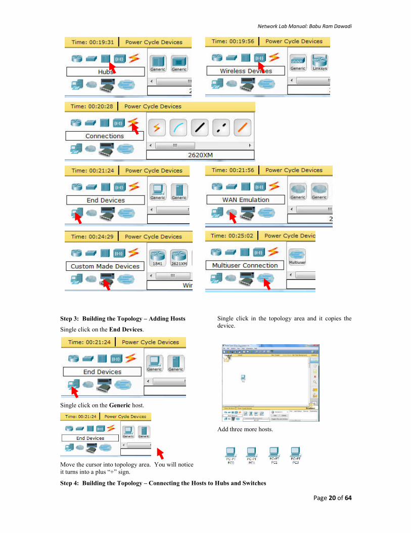
Network Lab Manual: Babu Ram Dawadi
Page 20 of 64
Step 3: Building the Topology – Adding Hosts
Single click on the End Devices.
Single click on the Generic host.
Move the cursor into topology area. You will notice it turns into a plus “+” sign.
Single click in the topology area and it copies the device.
Add three more hosts.
Step 4: Building the Topology – Connecting the Hosts to Hubs and Switches

Network Lab Manual: Babu Ram Dawadi
Page 21 of 64
Adding a Hub
Select a hub, by clicking once on Hubs and once on a Generic hub.
Add the hub by moving the plus sign “+” below PC0 and PC1 and click once.
Connect PC0 to Hub0 by first choosing Connections.
Perform the following steps to connect PC0 to Hub0:
1. Click once on PC0 2. Choose FastEthernet 3. Drag the cursor to Hub0 4. Click once on Hub0 and choose Port 0 5. Notice the green link lights on both the PC0 Ethernet NIC and the Hub0 Port 0 showing that the link is active.
1 2 3 4 5
Repeat the steps above for PC1 connecting it to Port 1 on Hub0. (The actual hub port you choose does not matter.)
Network Lab Manual: Babu Ram Dawadi
Page 22 of 64
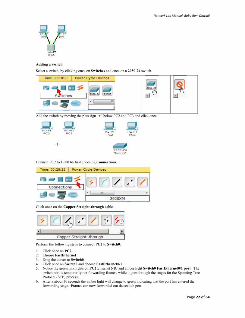
Adding a Switch
Select a switch, by clicking once on Switches and once on a 2950-24 switch.
Add the switch by moving the plus sign “+” below PC2 and PC3 and click once.
Connect PC2 to Hub0 by first choosing Connections.
Click once on the Copper Straight-through cable.
Perform the following steps to connect PC2 to Switch0:
1. Click once on PC2 2. Choose FastEthernet 3. Drag the cursor to Switch0 4. Click once on Switch0 and choose FastEthernet0/1 5. Notice the green link lights on PC2 Ethernet NIC and amber light Switch0 FastEthernet0/1 port. The
switch port is temporarily not forwarding frames, while it goes through the stages for the Spanning Tree Protocol (STP) process.
6. After a about 30 seconds the amber light will change to green indicating that the port has entered the forwarding stage. Frames can now forwarded out the switch port.

Network Lab Manual: Babu Ram Dawadi
Page 23 of 64
Task: Study yourself how Spanning Tree Protocol (STP) works?
1 2 3 4 5 6
Repeat the steps above for PC3 connecting it to Port 3 on Switch0 on port FastEtherent0/2. (The actual switch port you choose does not matter.)
Move the cursor over the link light to view the port number. Fa means FastEthernet, 100 Mbps Ethernet.
Step 5: Configuring IP Addresses and Subnet Masks on the Hosts
Before we can communicate between the hosts we need to configure IP Addresses and Subnet Masks on the devices.
Click once on PC0.
Choose the Config tab and click on Settings. It is here that you can change the name of PC0. It is also here where you would enter a Gateway IP Address, also known as the default gateway and the DNS Server IP Address. We will discuss this later, but this would be the IP address of the local router. If you want, you can enter the Gateway IP Address 172.16.1.1 and DNS Server IP Address 172.16.1.100, although it will not be used in this lab.

Network Lab Manual: Babu Ram Dawadi
Page 24 of 64
Click on Interface and then FastEthernet. Although we have not yet discussed IP Addresses, add the IP Address to 172.16.1.10. Click once in the Subnet Mask field to enter the default Subnet Mask. You can leave this at 255.255.0.0. We will discuss this later.
Also, notice this is where you can change the Bandwidth (speed) and Duplex of the Ethernet NIC (Network Interface Card). The default is Auto (autonegotiation), which means the NIC will negotiate with the hub or switch. The bandwidth and/or duplex can be manually set by removing the check from the Auto box and choosing the specific option.
Bandwidth - Auto
If the host is connected to a hub or switch port which can do 100 Mbps, then the Ethernet NIC on the host will choose 100 Mbps (Fast Ethernet). Otherwise, if the hub or switch port can only do 10 Mbps, then the Ethernet NIC on the host will choose 10 Mbps (Ethernet).
Duplex - Auto
Hub: If the host is connected to a hub, then the Ethernet NIC on the host will choose Half Duplex.
Switch: If the host is connected to a switch, and the switch port is configured as Full Duplex (or Autonegotiation), then the Ethernet NIC on the host will choose Full Duplex. If the switch port is configured as Half Duplex, then the Ethernet NIC on the host will choose Half Duplex. (Full Duplex is a much more efficient option.)
The information is automatically saved when entered.
To close this dialog box, click the “X” in the upper right.
Repeat these steps for the other hosts. Use the information below for IP Addresses and Subnet Masks.
Host IP Address Subnet Mask
PC0 172.16.1.10 255.255.0.0
PC1 172.16.1.11 255.255.0.0
PC2 172.16.1.12 255.255.0.0
PC3 172.16.1.13 255.255.0.0
Verify the information
To verify the information that you entered, move the Select tool (arrow) over each host.
Network Lab Manual: Babu Ram Dawadi
Page 25 of 64
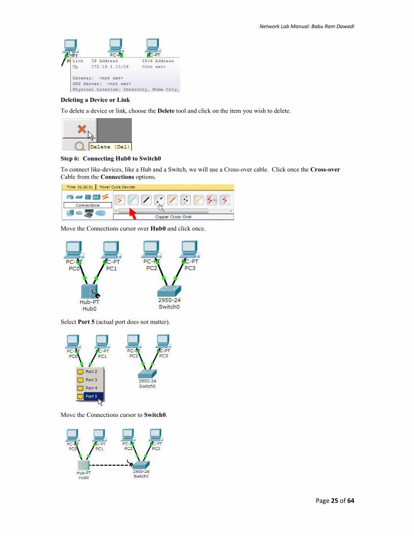
Deleting a Device or Link
To delete a device or link, choose the Delete tool and click on the item you wish to delete.
Step 6: Connecting Hub0 to Switch0
To connect like-devices, like a Hub and a Switch, we will use a Cross-over cable. Click once the Cross-over Cable from the Connections options.
Move the Connections cursor over Hub0 and click once.
Select Port 5 (actual port does not matter).
Move the Connections cursor to Switch0.

Network Lab Manual: Babu Ram Dawadi
Page 26 of 64
Click once on Switch0 and choose FastEthernet0/4 (actual port does not matter).
The link light for switch port FastEthernet0/4 will begin as amber and eventually change to green as the Spanning Tree Protocol transitions the port to forwarding.
Step 7: Verifying Connectivity in Real-time Mode
Be sure you are in Real-time mode.
Select the Add Simple PDU tool used to ping devices..
Click once on PC0, then once on PC3.
The PDU Last Status should show as Successful.
Resetting the Network
At this point we will want to reset the network, whenever you want to reset the network and begin the simulation again, perform the following tasks:
Click Delete in the PDU area.

Network Lab Manual: Babu Ram Dawadi
Page 27 of 64
Now, Power Cycle Devices and confirm the action.
Waiting for Spanning Tree Protocol (STP)
Note: Because Packet Tracer also simulates the Spanning Tree Protocol (later), at times the switch may show amber lights on its interfaces. You will need to wait for the lights to turn green on the switches before they will forward any Ethernet frames.
Step 8: Verifying Connectivity in Simulation Mode
Be sure you are in Simulation mode.
Deselect all filters (All/None) and select only ICMP.

Network Lab Manual: Babu Ram Dawadi
Page 28 of 64
Select the Add Simple PDU tool used to ping devices..
Click once on PC0, then once on PC3.
Continue clicking Capture/Forward button until the ICMP ping is completed. You should see the ICMP messages move between the hosts, hub and switch. The PDU Last Status should show as Successful. Click on Clear Event List if you do not want to look at the events or click Preview Previous Events if you do. For this exercise it does not matter.
Step 9: Saving the Topology
Perform the following steps to save the topology (uses .pkt file extension).

Network Lab Manual: Babu Ram Dawadi
Page 29 of 64
Opening Existing Topologies
Opening Existing PT Topologies
Task
1. Consider the following setup, Set IP addresses (192.168.50.0/27) on computers and verify the connectivity between PC2 to PC5, PC3 to PC4

Network Lab Manual: Babu Ram Dawadi
Page 30 of 64
2. Consider the following setup, Configure switch to create two VLANs (vlan 10 and vlan 20) in the figure below:(Switch ports fa0/1=>PC2, fa0/2=>PC3, fa0/3=>PC4,fa0/4=>PC5, put other ports in default vlan)
Configuration steps for Switch 1:
At the command line mode:
Switch>enable
Switch#conf ter
Switch(config)#vlan
Switch(config)#vlan 10
Switch(config-vlan)#name LAN_A
Switch(config-vlan)#vlan 20
Switch(config-vlan)#name LAN_B
Switch (config-vlan)#ctrl+z
Switch#sh vlan brief
VLAN Name Status Ports
---- -------------------------------- --------- ---------------
1 default active Fa0/1, Fa0/2, Fa0/3, Fa0/4
Fa0/5, Fa0/6, Fa0/7, Fa0/8
Fa0/9, Fa0/10, Fa0/11, Fa0/12
Fa0/13, Fa0/14, Fa0/15, Fa0/16
Fa0/17, Fa0/18, Fa0/19, Fa0/20
Fa0/21, Fa0/22, Fa0/23, Fa0/24
10 LAN_A active
20 LAN_B active
1002 fddi-default active
1003 token-ring-default active
1004 fddinet-default active
1005 trnet-default active
Switch#conf ter
Switch(config)#int fa0/1
Switch(config-if)#switchport mode access
Switch(config-if)#switchport access vlan 10
Switch(config)#int fa0/3
Switch(config-if)#switchport mode access
Switch(config-if)#switchport access vlan 10
Switch(config)#int fa0/2
Switch(config-if)#switchport mode access
Switch(config-if)#switchport access vlan 20
Switch(config)#int fa0/4
Switch(config-if)#switchport mode access
Switch(config-if)#switchport access vlan 20
Switch#sh vlan brief
VLAN Name Status Ports
---- -------------------------------- --------- -----------------------
1 default active Fa0/5, Fa0/6, Fa0/7, Fa0/8
Fa0/9, Fa0/10, Fa0/11, Fa0/12
Fa0/13, Fa0/14, Fa0/15, Fa0/16
Fa0/17, Fa0/18, Fa0/19, Fa0/20
Fa0/21, Fa0/22, Fa0/23, Fa0/24
10 LAN_A active Fa0/1, Fa0/3
20 LAN_B active Fa0/2, Fa0/4
1002 fddi-default active
1003 token-ring-default active
1004 fddinet-default active
1005 trnet-default active
3. Create VLAN 30 and VLAN 50 in the figure below and put switch to switch connection into trunk mode in the figure below. Test the connectivity between PC2 to PC6, PC3 to PC7
How to create trunk between switch 1 and switch 2
//At switch 1
Switch#conf ter
Enter configuration commands, one per line. End with CNTL/Z.

Network Lab Manual: Babu Ram Dawadi
Page 31 of 64
Switch(config)#int fa0/5
Switch(config-if)#switchport mode trunk
Switch(config-if)#switchport trunk native vlan 1
//at switch 2
Enter configuration commands, one per line. End with Ctrl+Z.
Switch#conf ter
Switch(config)#int fa0/1
Switch(config-if)#switchport mode trunk
Switch(config-if)#switchport trunk native vlan 1
Submit the work: Inter VLAN Communications: Router on Stick (consult instructor for more details). Refer
below diagram and configuration for practice.
Exercise:
1. Compare different Network Simulation Tools:
Packet Tracer, GNS3 and OpNet
2. Test the given task with GNS3
3. Discuss how useful the simulation tools in
learning.
VLAN Trunking Protocol (VTP) is a Cisco proprietary protocol that propagates the definition of Virtual Local Area Networks (VLAN) on the whole local area network. To do this, VTP carries VLAN information to all the switches in a VTP domain.
Trunk links are required to pass VLAN information between switches. A port on a Cisco switch is either an access port or a trunk port. Access ports belong to a single VLAN and do not provide any identifying marks on the frames that are passed between switches. Access ports also carry traffic that comes from only the VLAN assigned to the port. A trunk port is by default a member of all the VLANs that exist on the switch and carry traffic for all those VLANs between the switches. To distinguish between the traffic flows, a trunk port must mark the frames with special tags as they pass between the switches. Trunking is a function that must be enabled on both sides of a link.

Network Lab Manual: Babu Ram Dawadi
Page 32 of 64
LAB 6
Lab No
Description (Title)
5 Introduction to Packet Tracer, creating of a LAN and connectivity test in the LAN, creation of VLAN and VLAN Trunking.
6 Case Study: Campus Network Operation Center Visit.
7 Basic Router Configuration, Static Routing Implementation
Objective(S)
1. Understand the Historical Development of Campus Network and Research IPv6 Network. 2. Understand the physical servers and network equipment placement 3. Understand campus internet bandwidth distribution, authentication, and security systems/Firewalls 4. Understand the Network and Server operation process, management and troubleshooting.
Deliverables:
- Design the network connectivity diagram (using VISIO) of the Campus network showing the physical connection status.
- report the logical address distribution status. - summarize the knowledge what you gain in the field visit. - comment if any for the efficient design of the campus network.
Network Lab Manual: Babu Ram Dawadi
Page 33 of 64
LAB 7
Lab No Description (Title)
6 Case Study: Campus Network Operation Center Visit.
7 Basic Router Configuration, Static Routing Implementation
8 Implementation of Dynamic/interior/exterior routing (RIP, OSPF, BGP)
Objective(s)
understand basic commands for router configuration
understand the static routing, its advantages and drawbacks
Background
Static routing is useful in small network where numbers of routes are limited. In static routing we need to add route manually with IP route command. Like other routing methods static routing also has its pros and cons.
Advantage of static routing
It is easy to implement. It is most secure way of routing, since no information is shared with other routers. It puts no overhead on resources such as CPU or memory.
Disadvantage of static routing
It is suitable only for small network.
If a link fails static route cannot reroute the traffic.
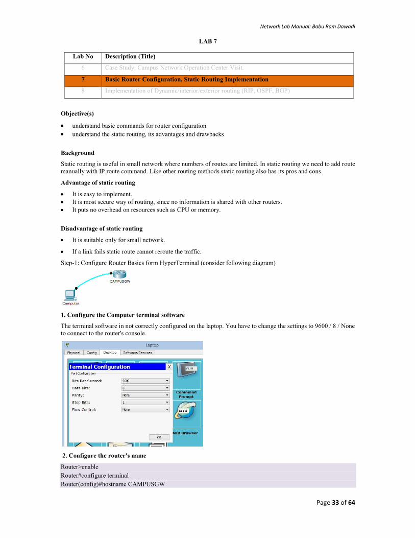
Step-1: Configure Router Basics form HyperTerminal (consider following diagram)
1. Configure the Computer terminal software
The terminal software in not correctly configured on the laptop. You have to change the settings to 9600 / 8 / None to connect to the router's console.
2. Configure the router's name
Router>enable
Router#configure terminal
Router(config)#hostname CAMPUSGW

Network Lab Manual: Babu Ram Dawadi
Page 34 of 64
3. Configure the enable password and secret to "cisco"
CAMPUSGW (config)#enable password cisco
CAMPUSGW (config)#enable secret cisco
4. Configure password encryption for this router
CAMPUSGW (config)#service password-encryption
5. Configure the console access
CAMPUSGW (config)#line console 0
CAMPUSGW (config-line)#password cisco
CAMPUSGW (config-line)#login
CAMPUSGW (config-line)#logging synchronous
CAMPUSGW (config-line)#exec-timeout 2 45
CAMPUSGW (config-line)#history size 10
Step 2: Static Routing Implementation. 1. Consider the following diagram and assign IP address to the corresponding interfaces as follows:
Device Connected from Connected to IP Address
PC0 FastEthernet0 Router0's FastEthernet0/0 10.0.0.2/8
Router0 FastEthernet0/0 PC0's FastEthernet0 10.0.0.1/8
Router0 Serial 0/0/0 Router1's serial0/0/0 192.168.0.253/30
Router1 Serial 0/0/0/ Router0's serial0/0/0 192.168.0.254/30
Router1 FastEthernet0/0 PC1's FastEthernet0 20.0.0.1/8
PC1 FastEthernet0 Router1's FastEthernet0/0 20.0.0.2/8
2. Assign IP address to each PC
3. Assign IP address to interfaces of router
Double click Router0 and click CLI and press Enter key to access command prompt of router.
Two interfaces FastEthernet0/0 and Serial0/0/0 of Router0 are used in this topology. By default interfaces on router are remain administratively down during the start up. We need to configure IP address and other parameters on interfaces before we could actually use them for routing. Interface mode is used to assign IP address and other parameters. Interface mode can be accessed from global configuration mode. Following commands are used to access global configuration mode.
Router>enable
Router#configure terminal //Enter configuration commands, one per line. End with CNTL/Z.
Router(config)#
From global configuration mode we can enter in interface mode. From there we can configure the interface. Following commands will assign IP address on FastEthernet0/0.

Network Lab Manual: Babu Ram Dawadi
Page 35 of 64
Router(config)#interface fastEthernet 0/0
Router(config-if)#ip address 10.0.0.1 255.0.0.0
Router(config-if)#no shutdown
Router(config-if)#exit
interface fastEthernet 0/0 command is used to enter in interface mode. ip address 10.0.0.2 255.0.0.0 command will assign IP address to interface. no shutdown command will bring the interface up. exit command is used to return in global configuration mode. Serial interface needs two additional parameters clock rate and bandwidth. Every serial cable has two ends DTE and DCE. These parameters are always configured at DCE end. We can use show controllers interface command from privilege mode to check the cable's end.
Router#show controllers serial 0/0/0
Interface Serial0/0/0
Hardware is PowerQUICC MPC860
DCE V.35, clock rate 2000000
[Output omitted]
Fourth line of output confirms that DCE end of serial cable is attached. If you see DTE here instead of DCE skip these parameters. Now we have necessary information let's assign IP address to serial interface.
Router#configure terminal
Enter configuration commands, one per line. End with CNTL/Z.
Router(config)#interface serial 0/0/0
Router(config-if)#ip address 192.168.0.253 255.255.255.252
Router(config-if)#clock rate 64000
Router(config-if)#bandwidth 64
Router(config-if)#no shutdown
Router(config-if)#exit
Router#configure terminal //Command is used to enter in global configuration mode.
Router(config)#interface serial 0/0/0 //Command is used to enter in interface mode.
Router(config-if)#ip address 192.168.0.253 255.255.255.252 //Command assigns IP address to interface. For serial link we usually use IP address from /30 subnet.
Router(config-if)#clock rate 64000 Router(config-if)#bandwidth 64 // In real life environment these parameters control the data flow between serial links and need to be set at service providers end. In lab environment we need not to worry about these values. We can use these values.
Router(config-if)#no shutdown //Command brings interface up.
Router(config-if)#exit //Command is used to return in global configuration mode.
We will use same commands to assign IP addresses on interfaces of Router1. Since we have provided clock rate and bandwidth on serial interface of Router0 we need not to assign them on serial interface of Router1. Following command will assign IP addresses on interface of Router1.
Router>enable
Router#configure terminal
Router(config)#interface fastEthernet 0/0
Router(config-if)#ip address 20.0.0.1 255.0.0.0
Router(config-if)#no shutdown
Router(config-if)#exit
Router(config)#interface serial 0/0/0
Router(config-if)#ip address 192.168.0.254 255.255.255.252
Router(config-if)#no shutdown
Router(config-if)#exit
Network Lab Manual: Babu Ram Dawadi
Page 36 of 64
4. Static route command explained
IP route command is used to configure the static route. In this section we will explain static route command in detail.
We have two commands to configure the static route.
Router(config)# ip route destination_network_# [subnet_mask] IP_address_of_next_hop_neighbor [administrative_distance] [permanent]
Or
Router(config)# ip route destination_network_# [subnet_mask] interface_to_exit [administrative_distance] [permanent] ip route: It is the command that add new route in routing table.
destination_network_#[subnet_mask]: This is the first parameter. It specifies the destination network address. We need to provide subnet mask if we are using sub-network. Sub-networks are the smaller network created from one large network in subnetting. If we are not using sub-network then we can omit the subnet mask value. It will parse automatically.
IP_address_of_next_hop_neighbor / interface_to_exit : This parameter provides a way to reach the destination network. Both commands use separate way to assign this value. First command provides the IP address of next hop neighbor. It tells router that if it receives a packet for destination [that we set in previous parameter], forward that packet to this next hop neighbor IP address.
Second command also do the same job but in different way. It specifies exit interface instead of next hop IP address. It tells router that if it receives a packet for the destination specified by previous parameter then exits that packet from this interface. Device attached on other end of this interface will take care of the packet.
administrative_distance
Administrative distance is the trustworthiness of route. Route with the lowest AD value will be chosen while forwarding the packet. By default static route has two AD values depending on the previous parameter. If you have used next hop neighbor IP address, then the default AD value will be 1. If you have used exit interface, then the default AD value will be 0. This parameter allows us to create multiple static routes for the same destination. For example we can create primary and backup path for the destination network. To create backup path, we need to set AD value to higher than default, such as 2 or 3. With this configuration router will use primary path. Due to some reason if primary route fails, the router will start using backup route automatically.
permanent
When a route goes down router will remove that from routing table. Permanent parameter will keep this route in routing table even if it goes down. Its optional parameter we can omit it. If we omit it, router will remove this route from routing table if it goes down. You might use this parameter for security reason if you never want packets to take another path.
Configure Default Route
By default when a packet arrives in interface, router checks destination filed in packet and compare it with routing table. If it finds a match for destination network then it will forward that packet from related interface. If it does not find a match in routing table then it will discard that packet. This is the default behavior of router. Default route allows us to override this behavior. Default route is a way to deal with all unmatched packets. If no match for destination network found in routing table then it would be forwarded to the default route.
Following command will set default route
Router(config)# ip route 0.0.0.0 0.0.0.0 IP_address_of_next_hop_neighbor [administrative_distance] [permanent]
Or
Router(config)# ip route 0.0.0.0 0.0.0.0 interface_to_exit [administrative_distance] [permanent]
Above command sets destination network to 0.0.0.0/0 that represents all networks.
Configure Static Route
Now we know that how IP route command is used to configure the static route. Let's implement it in our example topology. Run following command from global configuration mode in routers.

Network Lab Manual: Babu Ram Dawadi
Page 37 of 64
Router0
Router(config)#ip route 20.0.0.0 255.0.0.0 192.168.0.254 Router1
Router(config)#ip route 10.0.0.0 255.0.0.0 192.168.0.253 That's all we need to switch packet from one network to another. To verify the result we can use ping command. Access the command prompt of PC1 and use ping command to test the connectivity from PC0.
Your Task: consider the following diagram with IP address assignment, configure static routing and show the ping result between PC0 and PC4, PC1 and PC5.
Exercise:
1. What is adaptive and non-adaptive routing? Unicast and multicast routing? Distance vector and link state
routing?
2. What are routed and routing protocols?
3. Discuss VLSM with example. Also explain the CIDR with example.

Network Lab Manual: Babu Ram Dawadi
Page 38 of 64
LAB 8
Lab No Description (Title)
7 Basic Router Configuration, Static Routing Implementation
8 Implementation of Dynamic/Interior/Exterior Routing (RIP, OSPF, BGP)
9 Firewall (IPtables) Implementation, Router Access Control List (ACL)
Objective(s):
Understand the basic operation(s) of dynamic interior and exterior routing protocols.
Background:
Distance Vector Routing: Distance vector protocols (a vector contains both distance and direction), such as RIP,
determine the path to remote networks using hop count as the metric. A hop count is defined as the number of times
a packet needs to pass through a router to reach a remote destination. For IP RIP, the maximum hop is 15. A hop
count of 16 indicates an unreachable network. Two versions of RIP exist: version 1 and version 2. IGRP is another
example of a distance vector protocol with a higher hop count of 255 hops. A higher hop counts allows your network
to scale larger. One of the drawbacks of protocols, such as RIP and IGRP, is convergence time, which is the time it
takes for routing information changes to propagate through all your topology. Table 2-2 describes the characteristics
of distance vector protocols.
The name distance vector is derived from the fact that routes are advertised as vectors of (distance, direction), where
distance is defined in terms of a metric and direction is defined in terms of the next-hop router. For example,
"Destination A is a distance of 5 hops away, in the direction of next-hop router X." As that statement implies, each
router learns routes from its neighboring routers' perspectives and then advertises the routes from its own
perspective. Because each router depends on its neighbors for information, which the neighbors in turn may have
learned from their neighbors, and so on, distance vector routing is sometimes facetiously referred to as "routing by
rumor."
Common Characteristics
A typical distance vector routing protocol uses a routing algorithm in which routers periodically send routing updates to all neighbors by broadcasting their entire route tables. The preceding statement contains a lot of information. Following sections consider it in more detail.
Periodic Updates
Periodic updates means that at the end of a certain time period, updates will be transmitted. This period typically ranges from 10 seconds for AppleTalk's RTMP to 90 seconds for Cisco's IGRP. At issue here is the fact that if updates are sent too frequently, congestion may occur; if updates are sent too infrequently, convergence time may be unacceptably high.
Neighbors
In the context of routers, neighbors always means routers sharing a common data link. A distance vector routing protocol sends its updates to neighboring routers4 and depends on them to pass the update information along to their neighbors. For this reason, distance vector routing is said to use hop-by-hop updates.
Broadcast Updates
When a router first becomes active on a network, how does it find other routers and how does it announce its own presence? Several methods are available. The simplest is to send the updates to the broadcast address (in the case of IP, 255.255.255.255). Neighboring routers speaking the same routing protocol will hear the broadcasts and take appropriate action. Hosts and other devices uninterested in the routing updates will simply drop the packets.
Full Routing Table Updates
Most distance vector routing protocols take the very simple approach of telling their neighbors everything they know by broadcasting their entire route table, with some exceptions that are covered in following sections. Neighbors receiving these updates glean the information they need and discard everything else.

Network Lab Manual: Babu Ram Dawadi
Page 39 of 64
Characteristic Description
Periodic updates Periodic updates are sent at a set interval. For IP RIP, this interval is 30 seconds.
Broadcast updates Updates are sent to the broadcast address 255.255.255.255. Only devices running routing algorithms listen to these updates.
Full table updates When an update is sent, the entire routing table is sent.
Triggered updates Also known as Flash updates, these are sent when a change occurs outside the update interval.
Split horizon You use this method to stop routing loops. Updates are not sent out an outgoing interface from which the source network was received. This saves on bandwidth as well.
Count to infinity This is the maximum hop count. For RIP, it is 15 and for IGRP, it is 255.
Algorithm One algorithm example is Bellman-Ford for RIP.
Examples RIP and IGRP are examples of distance vector protocols.
Bellman-Ford Algorithm
The Bellman-Ford Algorithm computes the cost of the cheapest paths from a starting node to all other nodes in the graph. Thus, he can also construct the paths afterwards.
The algorithm proceeds in an interactive manner, by beginning with a bad estimate of the cost and then improving it until the correct value is found. The first estimate is: The starting node has cost 0, as his distance to itself is obviously 0. All other node have cost infinity, which is the worst estimate possible. Afterwards, the algorithm checks every edge for the following condition: Are the cost of the source of the edge plus the cost for using the edge smaller than the cost of the edge's target?
If this is the case, we have found a short-cut: It is more profitable to use the edge which was just checked, than using the path used so far. Therefore the cost of the edge's target get updated: They are set to the cost of the source plus the cost for using the edge (compare example on the right).
Looking at all edges of the graph and updating the cost of the nodes is called a phase. Unfortunately, it is not sufficient to look at all edges only once. After the first phase, the cost of all nodes for which the shortest path only uses one edge have been calculated correctly. After two phases all paths that use at most two edges have been computed correctly, and so on.
The green path from the starting node is the cheapest path. It uses 3 edges.
How many phases ware necessary? To answer this question, the observation that a shortest path has to use less edges than there are nodes in the graph. Thus, we need at most one phase less than the number of nodes in the graph. A shortest path that uses more edges than the number of nodes would visit some node twice and thus build a circle.
Construction of the shortest path
Each time when updating the cost of some node, the algorithm saves the edge that was used for the update as the predecessor of the node.
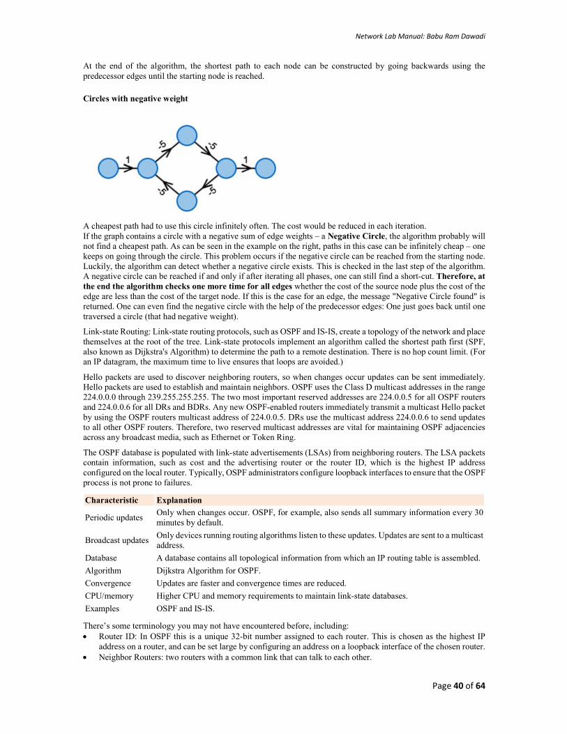
Network Lab Manual: Babu Ram Dawadi
Page 40 of 64
At the end of the algorithm, the shortest path to each node can be constructed by going backwards using the predecessor edges until the starting node is reached.
Circles with negative weight
A cheapest path had to use this circle infinitely often. The cost would be reduced in each iteration. If the graph contains a circle with a negative sum of edge weights – a Negative Circle, the algorithm probably will not find a cheapest path. As can be seen in the example on the right, paths in this case can be infinitely cheap – one keeps on going through the circle. This problem occurs if the negative circle can be reached from the starting node. Luckily, the algorithm can detect whether a negative circle exists. This is checked in the last step of the algorithm. A negative circle can be reached if and only if after iterating all phases, one can still find a short-cut. Therefore, at the end the algorithm checks one more time for all edges whether the cost of the source node plus the cost of the edge are less than the cost of the target node. If this is the case for an edge, the message "Negative Circle found" is returned. One can even find the negative circle with the help of the predecessor edges: One just goes back until one traversed a circle (that had negative weight).
Link-state Routing: Link-state routing protocols, such as OSPF and IS-IS, create a topology of the network and place themselves at the root of the tree. Link-state protocols implement an algorithm called the shortest path first (SPF, also known as Dijkstra's Algorithm) to determine the path to a remote destination. There is no hop count limit. (For an IP datagram, the maximum time to live ensures that loops are avoided.)
Hello packets are used to discover neighboring routers, so when changes occur updates can be sent immediately. Hello packets are used to establish and maintain neighbors. OSPF uses the Class D multicast addresses in the range 224.0.0.0 through 239.255.255.255. The two most important reserved addresses are 224.0.0.5 for all OSPF routers and 224.0.0.6 for all DRs and BDRs. Any new OSPF-enabled routers immediately transmit a multicast Hello packet by using the OSPF routers multicast address of 224.0.0.5. DRs use the multicast address 224.0.0.6 to send updates to all other OSPF routers. Therefore, two reserved multicast addresses are vital for maintaining OSPF adjacencies across any broadcast media, such as Ethernet or Token Ring.
The OSPF database is populated with link-state advertisements (LSAs) from neighboring routers. The LSA packets contain information, such as cost and the advertising router or the router ID, which is the highest IP address configured on the local router. Typically, OSPF administrators configure loopback interfaces to ensure that the OSPF process is not prone to failures.
Characteristic Explanation
Periodic updates Only when changes occur. OSPF, for example, also sends all summary information every 30 minutes by default.
Broadcast updates Only devices running routing algorithms listen to these updates. Updates are sent to a multicast address.
Database A database contains all topological information from which an IP routing table is assembled.
Algorithm Dijkstra Algorithm for OSPF.
Convergence Updates are faster and convergence times are reduced.
CPU/memory Higher CPU and memory requirements to maintain link-state databases.
Examples OSPF and IS-IS.
There’s some terminology you may not have encountered before, including: Router ID: In OSPF this is a unique 32-bit number assigned to each router. This is chosen as the highest IP
address on a router, and can be set large by configuring an address on a loopback interface of the chosen router. Neighbor Routers: two routers with a common link that can talk to each other.

Network Lab Manual: Babu Ram Dawadi
Page 41 of 64
Adjacency: a two-way relationship between two neighbor routers. Neighbors don’t always form adjacencies. LSA: Link State Advertisements are flooded; they describe routes within a given link. Hello Protocol: this is how routers on a network determine their neighbors and form LSAs. Area: a hierarchy. A set of routers that exchange LSAs, with others in the same area. Areas limit LSAs and
encourage aggregate routes.
OSPF is a link-state routing protocol, as we’ve said. Think of this as a distributed map of the network. To get this information distributed, OSPF does three things.
First, when a router running OSPF comes up it will send hello packets to discover its neighbors and elect a designated router. The hello packet includes link-state information, as well as a list of neighbors. Providing information about your neighbor to that neighbor serves as an ACK, and proves that communication is bi-directional. OSPF is smart about the layer 2 topology: if you’re on a point-to-point link, it knows that this is enough, and the link is considered “up.” If you’re on a broadcast link, the router must wait for an election before deciding if the link is operational.
The election ballot can be stuffed, with a Priority ID, so that you can ensure that your beefiest router is the DR. Otherwise, the largest IP address wins. The key idea with a DR and backup DR (BDR) is that they are the ones to generate LSAs, and they must do database exchanges with other routers in the subnet. So, non-designated routers form adjacencies with the DR. The whole DR/BDR design is used to keep the protocol scalable. The only way to ensure that all routers have the same information is to make them synchronize their databases. If you have 21 routers, and want to bring another one up, then you’d have to form 21 new adjacencies. If you centralize the database, with a backup (just in case), then adding more becomes an easy to manage linear problem.
The database exchange is part of bringing up adjacencies after the hello packets are exchanged, and it’s very important. If the databases are out of sync, we could risk routing loops, black holes and other perils. The third part of bringing up an adjacency is Reliable Flooding, or LSA exchange.
The details of an LSA, as well as a more advanced discussion of areas will be the topic of the next Networking 101. For now, just know that area zero is special, and if you have multiple areas, they must all touch area zero. This is also called the Backbone Area. There are different types of areas in OSPF, and it can get really crazy when you throw in Virtual Links to allow two areas to speak without hitting area zero. Alas, there also are different types of routers in OSPF.
ABR An Area Border Router is a router that is in area zero, and one or more other areas.
DR, BDR A Designated Router, as we said, is the router that keeps the database for the subnet. It sends and receives updates (via multicast) from the other routers in the same network.
ASBR The Autonomous System Boundary Router is very special, but confusing. The ASBR connects one or more AS, and exchanges routes between them. The ASBR’s purpose is to redistribute routes from another AS into its own AS.
The concept of redistribution finally rears its head: let’s say we have a router, an internal-only router (not a BR), and we wish to connect it to a new network that we don’t control. After this connection is made, we have a few options. We can fire up a non-IGP routing protocol, like BGP, to exchange routes. Alternatively, we could decide that a summary route is good enough, and hard-code a static route to the new network in this router. Anything directly using this router for this destination would be able to get to the new network, but OSPF doesn’t know about it. To make that happen, we ‘redistribute” the miscellaneous information into OSPF. We wouldn’t want to feed 200K+ routes from BGP into OSPF, but if we went the static route, we’d definitely want to propagate that information so everyone in our AS could get to the new place. As soon as we tell our internal router that it should redistribute static routes into OSPF, it becomes an ASBR, and the entire network can reach the new network.
Consider the following topology with IP address distribution, test the connectivity between Pc0 and PC1
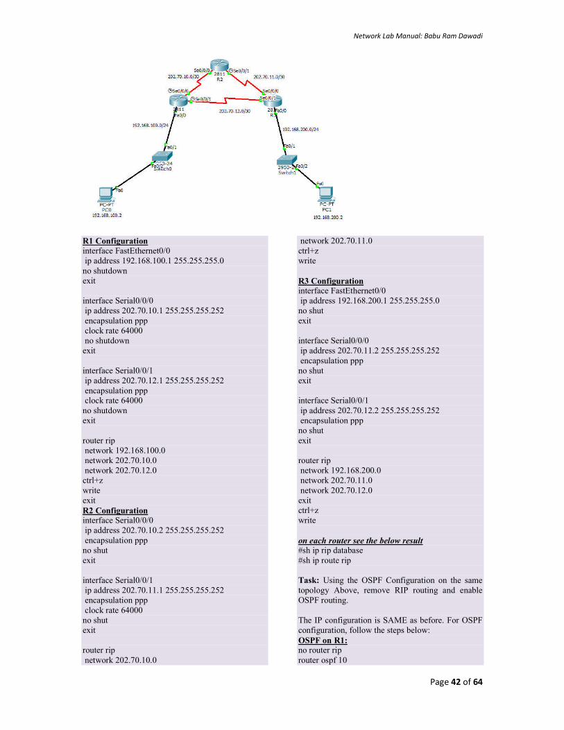
Network Lab Manual: Babu Ram Dawadi
Page 42 of 64
R1 Configuration interface FastEthernet0/0 ip address 192.168.100.1 255.255.255.0 no shutdown exit interface Serial0/0/0 ip address 202.70.10.1 255.255.255.252 encapsulation ppp clock rate 64000 no shutdown exit interface Serial0/0/1 ip address 202.70.12.1 255.255.255.252 encapsulation ppp clock rate 64000 no shutdown exit router rip network 192.168.100.0 network 202.70.10.0 network 202.70.12.0 ctrl+z write exit R2 Configuration interface Serial0/0/0 ip address 202.70.10.2 255.255.255.252 encapsulation ppp no shut exit interface Serial0/0/1 ip address 202.70.11.1 255.255.255.252 encapsulation ppp clock rate 64000 no shut exit router rip network 202.70.10.0
network 202.70.11.0 ctrl+z write R3 Configuration interface FastEthernet0/0 ip address 192.168.200.1 255.255.255.0 no shut exit interface Serial0/0/0 ip address 202.70.11.2 255.255.255.252 encapsulation ppp no shut exit interface Serial0/0/1 ip address 202.70.12.2 255.255.255.252 encapsulation ppp no shut exit router rip network 192.168.200.0 network 202.70.11.0 network 202.70.12.0 exit ctrl+z write on each router see the below result #sh ip rip database #sh ip route rip Task: Using the OSPF Configuration on the same topology Above, remove RIP routing and enable OSPF routing. The IP configuration is SAME as before. For OSPF configuration, follow the steps below: OSPF on R1: no router rip router ospf 10

Network Lab Manual: Babu Ram Dawadi
Page 43 of 64
router-id 1.1.1.1 network 192.168.100.0 0.0.0.255 area 0 network 202.70.10.0 0.0.0.3 area 0 network 202.70.12.0 0.0.0.3 area 0 ctrl + z Write Exit OSPF on R2: no ip rip router ospf 10 router-id 2.2.2.2 network 202.70.10.0 0.0.0.3 area 0 network 202.70.11.0 0.0.0.3 area 0 ctrl + z Write Exit
OSPF on R3: no ip rip router ospf 10 router-id 3.3.3.3 network 202.70.11.0 0.0.0.3 area 0 network 202.70.12.0 0.0.0.3 area 0 network 192.168.200.0 0.0.0.255 area 0 ctrl + z Write Exit On each router see the below #sh ip ospf #sh ip ospf neighbor #sh ip ospf route #sh ip ospf interface #sh ip ospf database //analyze the result
Your Task: Implement BGP configuration for the following scenario
Exercise 1. What is count to infinity problem? 2. What are the different RIP timer? 3. How does bellmann-ford algorithm works? 4. What is autonomous system? 5. What are ABR, ASBR, DR/BDR? 6. Discuss Dijkstra’s shortest path algorithm. 7. How OSPF router come into fully adjacency state?

Network Lab Manual: Babu Ram Dawadi
Page 44 of 64
LAB 9
8 Implementation of Dynamic/interior/exterior routing (RIP, OSPF, BGP)
9 Firewall Implementation, Router Access Control List (ACL)
10 Packet capture and header analysis by wire-shark (TCP,UDP,IP)
Objective(s):
Understand the router firewall: Access Control Lists (ACLs).
Background:
Packet filtering at the network level can be achieved by applying the Access Control Lists (ACLs)1 at the router called
router firewall. ACLs at the router filter the inbound traffic while it permit or deny packets based on source IP/network
and destination IP/network, IP, TCP,UDP protocol information. Generally we use the ACLs to provide a basic level of
security for accessing our network. Access lists can allow one host to access a part of network and prevent another host
from accessing the same area.
A standard ACL can be used for several purpose. In this lab we will see how it can be used in controlling the unwanted
network traffic. With standard ACL, we can define certain conditions for the network traffic passing through the router.
By default router does not filter any traffic unless we manually put an ACL.
There are two types of ACLs:
1. Standard ACL: permits or denies packets based on source and destination IP address and also based on IP protocol
information. Valid ACL ID range is: 1 - 99 or a string. Standard ACL shall be created in three ways viz. i) Classic Numbered
ii) Modern Numbered iii) Modern Named This lab tutorial presents the creation of all three Standard ACLs.
2. Extended ACL: it permits or denies packets based on source and destination IP address and also based on IP protocol
information. Valid Extended ACL ID range is: 100 - 199 or a string
When creating an access list, we define criteria that are applied to each packet that is processed by the router; the router decides whether to forward or block each packet on the basis of whether or not the packet matches the criteria.
By default when a router receives a packet in interface, it takes following actions:
Grab destination address from the packet Find an entry for destination address in routing table If match found, forwards the packet from associate interface If no match found, discard the packet immediately.
Suppose for the following network configuration, the router that only 10.0.0.10 has the right to access the 30.0.0.1. To match with this condition router will take following actions:-
Grab source and destination address from the packet Match both addresses with given condition If packet is not arrived from 10.200.10.20, drop the packet immediately.
1 http://www.hp.com/rnd/support/manuals/pdf/release_06628_07110/Bk2_Ch3_ACL.pdf http://www.cisco.com/c/en/us/td/docs/ios/12_2/security/configuration/guide/fsecur_c/scfacls.pdf
Access lists of some protocols must be identified by a name, and access lists of other protocols must be identified by a number. Some protocols can be identified by either a name or a number. When a number is used to identify an access list, the number must be within the specific range of numbers that is valid for the protocol. Cisco Access Control Lists are the set of conditions grouped together by name or number. These conditions are used in filtering the traffic passing from router. Through these conditions we can filter the traffic; either when it enters in router or when it exits from router.

Network Lab Manual: Babu Ram Dawadi
Page 45 of 64
If packet is not destined to 192.168.100.10, drop the packet immediately. If both condition match, find an entry for destination address in routing table If match found, forwards the packet from associate interface If no match found, discard the packet immediately.
Tutorial Steps: Consider the case scenario as follows:
IOE Pulchowk Campus network is divided into four cluster with its own routing domain and Autonomous system Number
(say: 3245). We need to configure routers and network with the APNIC provided IP block as: 202.70.91.0/24. For each
network section a separate ACL is required. The IP block distributions are as follows (Ref:
http://www.computernetworkingnotes.com/ccna-study-guide/configure-standard-access-control-list-step-by-step-
guide.html )
Network Name
Total Hosts
Network Number Subnet Mask Wild Card Mask
ACL Number/Name
NCR 12 202.70.91.0/28 255.255.255.240 0.0.0.15 10 COMPLEX 120 202.70.91.16/25 255.255.255.128 0.0.0.127 COMPLEX CIMISH 59 202.70.91.144/27 255.255.255.192 0.0.0.63 CIMISH QUASD 6 202.70.91.208/29 255.255.255.248 0.0.0.7 20
Figure: Network Diagram (Topology)

Network Lab Manual: Babu Ram Dawadi
Page 46 of 64
The ip address setting plan is as follows:
Device Name Interface Name IP Address Router 0 Serial 0/0/0 202.70.91.253/30
Serial 0/0/1 202.70.91.249/30 Gig 0/0 202.70.91.1/28
Router 1 Serial 0/0/0 202.70.91.254/30 Serial 0/0/1 202.70.91.241/30 Gig 0/0 202.70.91.17/25
Router 2 Serial 0/0/0 202.70.91.250/30 Serial 0/0/1 202.70.91.242/30 Gig 0/0 202.70.91.145/26 Gig 0/1 202.70.91.209/28
Server 0-3 Server port 202.70.91.2-4/28 Laptop 0 Client port 202.70.91.5/28 PC3 Client port 202.70.91.18/25 Laptop 2-3 Client port 202.70.91.19-20/25 PC1 Client port 202.70.91.146/26 PC2 Client port 202.70.91.147/26 Laptop-1 Client port 202.70.91.148/26 PC4 Client port 202.70.91.210/29 Laptop-4 Client port 202.70.91.211/29 PC5 Client port 202.70.91.212/29
Based on the ip distribution and network topology sketched, 1) create network topology in your packet tracer tool 2) Assign
essential IP addresses as shown in above table with given network. 3) Configure RIPv2 protocol in R1, R2 and R2 for IP
routing. The ACL requirement shall be as follows.
1. COMPLEX network section should be able to access only NCR. It should not be able to access other networks (QUASD & CIMISH).
1. One user (PC1) from CIMISH network section should not be able to access anything except its own section.
2. One user (Laptop1) from CIMISH network section should be able to access all other networks but not COMPLEX network section. (at complex acl: deny 202.70.91.150 0.0.0.0)
It is assumed that you are able to configure each device ip address in the given network topology and also able to enable RIP practiced in previous labs that is the pre-requisite for this lab. You are now provided with tips about how to enable ACL in the network based on the above requirements.
On Router-0, create the following ACL enable conf ter ip access-list standard 10 deny 202.70.91.16 0.0.0.127 deny 202.70.91.208 0.0.0.7 permit any ctrl+Z wr
On Router-1, create the following ACL enable conf ter ip access-list standard complex deny host 202.70.91.150 permit any ctrl+z wr
On Router-0, create the following ACL enable conf ter ip access-list standard 20 deny 202.70.91.0 0.0.0.15 deny 202.70.91.16 0.0.0.127 deny 202.70.91.128 0.0.0.63 permit any exit ip access-list standard cimish deny host 202.70.91.146 deny 202.70.91.0 0.0.0.127
After creating those ACLs, now test the connectivity as per the requirements (the ACL has not yet been applied) Ping test from pc3 to server 0 PC>ping 202.70.91.2 Pinging 202.70.91.2 with 32 bytes of data: Reply from 202.70.91.2: bytes=32 time=10ms TTL=126 Reply from 202.70.91.2: bytes=32 time=1ms TTL=126 Reply from 202.70.91.2: bytes=32 time=1ms TTL=126 Reply from 202.70.91.2: bytes=32 time=1ms TTL=12

Network Lab Manual: Babu Ram Dawadi
Page 47 of 64
permit any ctrl+z wr
Ping test from pc1 to server0 PC>ping 202.70.91.2 Pinging 202.70.91.2 with 32 bytes of data: Reply from 202.70.91.2: bytes=32 time=2ms TTL=126 Reply from 202.70.91.2: bytes=32 time=1ms TTL=126 Reply from 202.70.91.2: bytes=32 time=1ms TTL=126 Reply from 202.70.91.2: bytes=32 time=1ms TTL=126
Ping test from pc4 to server0 PC>ping 202.70.91.2 Pinging 202.70.91.2 with 32 bytes of data: Reply from 202.70.91.2: bytes=32 time=2ms TTL=126 Reply from 202.70.91.2: bytes=32 time=1ms TTL=126 Reply from 202.70.91.2: bytes=32 time=1ms TTL=126 Reply from 202.70.91.2: bytes=32 time=1ms TTL=126
Ping test from pc3 to pc4 PC>ping 202.70.91.210 Pinging 202.70.91.210 with 32 bytes of data: Reply from 202.70.91.210: bytes=32 time=1ms TTL=126 Reply from 202.70.91.210: bytes=32 time=1ms TTL=126 Reply from 202.70.91.210: bytes=32 time=1ms TTL=126 Reply from 202.70.91.210: bytes=32 time=1ms TTL=126
Ping test from pc1 to pc3 PC>ping 202.70.91.18 Pinging 202.70.91.18 with 32 bytes of data: Reply from 202.70.91.18: bytes=32 time=2ms TTL=126 Reply from 202.70.91.18: bytes=32 time=1ms TTL=126 Reply from 202.70.91.18: bytes=32 time=2ms TTL=126 Reply from 202.70.91.18: bytes=32 time=1ms TTL=126
Now apply the ACL in to the corresponding interfaces with inbound and outbound settings. On router 0, in configuration mode, issue the following acl int gig 0/0 ip access-group 10 out
On router-1, in configuration mode, issue the following acl
int gig 0/0 ip access-group complex out
On router-2, in configuration mode, issue the following acl
int gig 0/0 ip access-group cimish in exit int gig 0/1 ip access-group 20 out
ctrl+z
wr
Your Task: After applying ACLs, Now repeat the ping test done before and analyze the results.
Refer [3] for more details about ACL.
Exercise:
1. What is wild card mask? Explain with example.
2. Elaborate the concept of extended ACL
3. Apply ACL for the following
a. Allow only www traffic on server 0 (web server).
b. Allow only DNS (UDP, 53) traffic on server 1 (DNS server)

Network Lab Manual: Babu Ram Dawadi
Page 48 of 64
LAB 10
Lab No
Description (Title)
9 Firewall (IPtables) Implementation, Router Access Control List (ACL)
10 Packet capture and header analysis by Wireshark (TCP,UDP,IP)
11 Basic Frame Relay Implementation with PVC
Objective(s)
1. Understand the packet analysis tool
2. Understand TCPU/UDP/IP header
Background
Wireshark, a network analysis tool formerly known as Ethereal, captures packets in real time and display them in human-readable format. Wireshark includes filters, color-coding and other features that let you dig deep into network traffic and
inspect individual packets.
This tutorial will get you up to speed with the basics of capturing packets, filtering them, and inspecting them. You can use Wireshark to inspect a suspicious program’s network traffic, analyze the traffic flow on your network, or troubleshoot network problems.
Capturing Packets
After downloading and installing Wireshark, you can launch it and click the name of an interface under Interface List to start capturing packets on that interface. For example, if you want to capture traffic on the wireless network, click your wireless interface. You can configure advanced features by clicking Capture Options, but this isn’t necessary for now.
As soon as you click the interface’s name, you’ll see the packets start to appear in real time. Wireshark captures each packet sent to or from your system. If you’re capturing on a wireless interface and have promiscuous mode enabled in your capture options, you’ll also see other the other packets on the network.
Click the stop capture button near the top left corner of the window when you want to stop capturing traffic.

Network Lab Manual: Babu Ram Dawadi
Page 49 of 64
Color Coding
You’ll probably see packets highlighted in green, blue, and black. Wireshark uses colors to help you identify the types of traffic at a glance. By default, green is TCP traffic, dark blue is DNS traffic, light blue is UDP traffic, and black identifies TCP packets with problems — for example, they could have been delivered out-of-order.
Sample Captures
If there’s nothing interesting on your own network to inspect, Wireshark’s wiki has you covered. The wiki contains a page of sample capture files that you can load and inspect.
Opening a capture file is easy; just click Open on the main screen and browse for a file. You can also save your own captures in Wireshark and open them later.
Filtering Packets
If you’re trying to inspect something specific, such as the traffic a program sends when phoning home, it helps to close down all other applications using the network so you can narrow down the traffic. Still, you’ll likely have a large amount of packets to sift through. That’s where Wireshark’s filters come in.

Network Lab Manual: Babu Ram Dawadi
Page 50 of 64
The most basic way to apply a filter is by typing it into the filter box at the top of the window and clicking Apply (or pressing Enter). For example, type “dns” and you’ll see only DNS packets. When you start typing, Wireshark will help you auto-complete your filter.
You can also click the Analyze menu and select Display Filters to create a new filter.
Another interesting thing you can do is right-click a packet and select Follow TCP Stream.
You’ll see the full conversation between the client and the server.

Network Lab Manual: Babu Ram Dawadi
Page 51 of 64
Close the window and you’ll find a filter has been applied automatically — Wireshark is showing you the packets that make up the conversation.
Inspecting Packets
Click a packet to select it and you can dig down to view its details.
You can also create filters from here — just right-click one of the details and use the Apply as Filter submenu to create a filter based on it.

Network Lab Manual: Babu Ram Dawadi
Page 52 of 64
Wireshark is an extremely powerful tool, and this tutorial is just scratching the surface of what you can do with it. Professionals use it to debug network protocol implementations, examine security problems and inspect network protocol internals.
Your Task: Capture the TCP, UDP and IP traffic and analyze the headers with the meaning of every headers field
described.

Network Lab Manual: Babu Ram Dawadi
Page 53 of 64
LAB 11
Lab No Description (Title)
10 Packet capture and header analysis by Wireshark (TCP,UDP,IP)
11 Basic Frame Relay Implementation with PVC
12 DNS, Web, DHCP, FTP server configuration
Objective(s):
To understand Frame Relay Network Configuration and Operation
Background:
Frame Relay is one of the most popular WAN service deployed over the past decade. Even though several advanced technologies (such as VPN, ATM) are available today, Frame Relay still rocks and will be in near future due to its features,
benefits and lower cost in comparison with other point to point wan services. For example have look on following figure that illustrates a network with simple point to point leased line connection. Frame Relay turns physical interface in virtual interfaces. With virtual interface Frame Relay can effectively handle this network or even bigger network with single serial interface. With Frame Relay implementation, we still need 6 connections to connect all these routers with each other. But instead of physical lines, Frame Relay uses virtual lines to connect all these locations. The biggest benefit of these virtual lines is that we do not need equal physical interfaces on router to connect them. We can connect multiple virtual lines with single interface.
In Frame Relay terminology virtual connection lines are known as Virtual Circuits (VCs). There are two types of VCs; PVCs and SVCs. The difference between these two are:
Frame Relay PVCs (Permanent Virtual Circuits) Frame Relay SVCs (Switched Virtual Circuits)
PVC is just like a leased line that is once configured will stay there until we manually reconfigure it.
SVC is just like a telephone connection that is dynamically built whenever we have data to transmit and once transmission is over it will be terminated.
If we have regular data for transmission then PVC is the best choice.
If we have periodical data for transmission then SVC is the right choice.
PVCs need a lot of manual configuration. SVCs need less configuration in comparison with PVCs.
Once PVC is built there is no delay before data transmission.
Since SVC is built each time whenever we send data, therefore a small delay before data transmission is expected.
Whether we use it or not, we have to pay for entire billing cycle.
We need to pay only when we actually use it.
Frame Relay uses a lot of terms to describe its components and functions.
DTE (Data Terminal Equipment) is a device (usually a router or PC) that converts data frame into signals and reconvert received signals in data frame. DTE device communicates with DCE device.
A CSU/DSU (Channel Service Unit/Data Service Unit) is a device that converts data signal between LAN network and WAN network. LAN network and WAN network uses separate communication technology. A CSU/DSU understands both technologies. DSL and cable modems are the example of CSU/DSU.
DCE (Data circuit terminating equipment) is a device (usually modem, CSU/DSU or Frame Relay switch) that provides clock rate and synchronization.
Access Link: Connection line between DTE and DCE.

Network Lab Manual: Babu Ram Dawadi
Page 54 of 64
Frame Relay cloud: Frame Relay cloud refers Telco companies’ internal infrastructure.
VC: A VC is the logical path between two endpoint DTEs.
Access Rate: This is the maximum speed of purchased connection. Access link should be clocked on this speed. Access
rate is the maximum speed at which data can be transmitted.
CIR (Committed Information Rate)
This is the guaranteed bandwidth that we will get from provider for a VC. In congestion we could be sure about this bandwidth. CIR is the maximum bandwidth at which data will be delivered guaranteed. Let’s understand these value with an example. Suppose, there are three networks connected with a frame relay switch sharing single path. Network1 and Network2 purchased a connection with access rate of 128Kbps and CIR of 64 Kbps. Network3 purchased connection with access rate of 64Kbps and CIR of 64 Kbps. If access rate and CIR rate is equal then Frame relay connection is pretty much works like a leased line. Network3 is paying for 64Kbps speed and in return, getting a guaranteed speed of 64Kbps from frame Relay Company. So for network3 this connection will work just like a leased line of 64Kbps where you will get what you will pay for.Instead of fix bandwidth, network1 and network2 opt for a flexible connection where access rate and CIR rate is different. For this connection they have to spend a little extra money. They will be charged for 64Kbps guaranteed (CIR) + additional bandwidth (if available under certain terms and conditions). Additional bandwidth will be provided on share basis. If all other users are transferring data at any particular time then they will get a minimum bandwidth of 64Kbps at that time. If no other user is transferring data at any specific time then they will get a maximum bandwidth of 128 Kbps on that time.
If no other user is transferring data then maximum (128 Kbps) bandwidth would be available. If all other users are transferring data then minimum (64 Kbps) bandwidth would be available. If some users are transferring data then bandwidth speed may be anywhere between 64Kbps and 128 Kbps. Anything beyond the CIR is marked as burst. There are two types of burst:-
BC (committed burst rate)
A small amount of additional bandwidth that is allowed to handle small burst in traffic.
BE (excessive burst rate)
Remaining amount of bandwidth. If Telco allows, we can also set bandwidth at this rate. Connection rarely works at this speed.
Oversubscription
When we add up all CIRs (CIR + Bc + BE ) and sum exceed the access rate then it would be considered as oversubscription. Usually oversubscription is not allowed. So any data that fall in oversubscription category will be dropped.
Frame Relay Congestion Control
Since users share bandwidth, congestion is common in Frame Relay. We should avoid sending additional data if network is facing congestion at any particular time. Frame Relay uses three bits to manage congestion:-
Discard Eligibility (DE)
Any packet beyond CIR is eligible to discard if Frame Relay network is facing congestion. DE bit is set in header. During congestion, Frame Relay switch will drop all the packets that are marked (set to on) with DE bit. If there is no congestion, packet will be allowed to cross the frame relay network.
Forward Explicit Congestion Notification (FECN)
If there is congestion in network then frame relay switch will set FECN bit to on (1) in data frame header. This way destination router will learn about congestion in VC.
Backward Explicit Congestion Notification (BECN)
Once the frames with congestion bit on arrived at destination router (DTE) , the destination router will send back a frame in reverse direction with BECN bit on in header of frame. Once source receive this frame it will learn about the congestion and slow down the data transmission on that VC. If Frame Relay carrier experiences less or no congestion, you will get a good speed and great service at competitively low price. If Frame Relay carrier experiences constantly congestion, you will get a poor service since most of your fames will be dropped.
Frame Relay LMI (Local Management Interface) protocol
Before data transmission DTE confirms the status of remote end. It sends data only if remote end is up. To know the status of each other’s, devices exchange Keepalive messages. If one end does not receive a Keepalive message from other end in specified time then it would assume that remote end is down. Keepalive messages are exchanged between directly

Network Lab Manual: Babu Ram Dawadi
Page 55 of 64
connected devices. For example in leased line where two devices connect with each other via direct link, will exchange Keepalive messages. But in Frame Relay devices connect with each other via the Frame Relay switches, so they will exchange Keepalive message with Frame Relay switches. Frame Relay uses LMI protocol to exchange the Keepalive messages between DTE (connection end point) and DCE (last frame relay switch that is directly connected with the end point). DTE (Routers) send LMI status enquiry messages to the connected DCE (Frame Relay switch). If DCE (Frame Relay) is up then it will respond with LMI status reply message. If DTE does not get response form DCE then it will assume that either access link or frame relay switch is down. Besides LMI status enquiry DTE also asks for full status updates. In response DCE respond with all information that is related to DTE. This information includes the status of VCs which are connected to the DTE and their configuration values (CIR, BC, BE and DLCIs). LMI status enquiry: - A simple query asking simple question “Are you there”. Response of this query is also simple “Yes I am here”.
LMI full status enquiry: - A complete query seeking full information “Tell me everything that is related to me”. Response of this query contains all information that is related to DTE “Here is all information which is related to you”.
There are three types of LMI Cisco, ANSI, and Q.933A. Each LMI type is slightly different from other two. Therefor they are not compatible with each other. We must have to use same LMI option on both ends. In next part of this article we will learn how to configure LMI type.
Frame Relay DLCI (data link connection identifiers)
Frame Relay allows us to connect multiple VCs with single physical access link. In first example of this tutorial, we connected six VCs with single physical link (serial interface). Basically we divided a serial interface in six sub-interfaces and assigned one VC with each sub interface. Frame Relay must need to know which sub-interface is connected with which VC before it can transmit the data. Frame Relay uses DLCI (data link connection identifiers) number to map the interface with VC. JSince a VC has two ends it need two DLCI number, one for each end. DLCI value is provided by Telco. Probably we may get same or different DLCI number for both ends. DLCI number need to be unique only between Frame Relay switch and DTE router. If we received different DLCI number for both end then Frame Relay would convert DLCI number in midway. The setup here will use the hub and spoke configuration, Router0 is the hub, Router1 and Router2 are the spokes. Point-to-Point sub interfaces are created and PVCs (Permanent Virtual Circuits) are established between Router0 and Router1 and Router0 and Router2. So the Spoke routers communicate via Router0. (refer [4] for detail explanation).
Frame Relay Switch Configuration
Configure the serial interfaces of the Frame Relay switch (Cloud-PT, Cloud0) as follows Serial0
DLCI Name
102 R0-R1
103 R0-R2
Serial1
DLCI Name
201 R1-R0
Serial2
DLCI Name
301 R2-R0
Click on the frame relay switch and Select the frame relay config tab and create the following links
From Port Sublink To Port Sublink
Serial0 R0-R1 Serial1 R1-R0
Serial0 R0-R2 Serial2 R2-R0
Configure the routers
The configuration of each router is shown below Router0 (Hub)

Network Lab Manual: Babu Ram Dawadi
Page 56 of 64
R0>enable R0#configure terminal R0(config)#interface Serial 2/0 R0(config-if)#no shutdown R0(config-if)#encapsulation frame-relay R0(config-if)#exit R0(config)#interface Serial 2/0.102 point-to-point R0(config-subif)#ip address 192.168.1.1 255.255.255.252 R0(config-subif)#frame-relay interface-dlci 102 R0(config-subif)#exit R0(config)#interface Serial 2/0.103 point-to-point R0(config-subif)#ip address 192.168.1.5 255.255.255.252 R0(config-subif)#frame-relay interface-dlci 103 R0(config-subif)#exit R0(config)#router rip R0(config)#network 192.168.1.0 R0(config-subif)#wr
Router1 (Spoke) R1>enable R1#configure terminal R1(config)#interface Serial 2/0 R1(config-if)#no shutdown R1(config-if)#encapsulation frame-relay R1(config-if)#exit R1(config)#interface Serial 2/0.201 point-to-point R1(config-subif)#ip address 192.168.1.2
255.255.255.252 R1(config-subif)#frame-relay interface R1(config-subif)#frame-relay interface-dlci 201 R1(config-subif)#exit R1(config)#router rip R1(config)#network 192.168.1.0 R1(config-subif)#wr
Router2 (Spoke) R2>enable R2#configure terminal R2(config)#interface Serial 2/0 R2(config-if)#no shutdown R2(config-if)#encapsulation frame-relay R2(config-if)#exit R2(config)#interface Serial 2/0.301 point-to-point R2(config-subif)#ip address 192.168.1.6 255.255.255.252 R2(config-subif)#frame-relay interface-dlci 301 R2(config-subif)#exit R2(config)#router rip R2(config)#network 192.168.1.0 R2(config-subif)#write Task: Ping the routers & check connectivity. R2#ping 192.168.1.1 R2#ping 192.168.1.5

Network Lab Manual: Babu Ram Dawadi
Page 57 of 64
LAB 12
Lab No
Description (Title)
11 Basic Frame Relay Implementation with PVC
12 DNS, Web, DHCP, FTP server configuration
13 Case study, design, presentation
DNS configuration on Linux Machine
Administering DNS in Linux is in fact really simple. The first-time configuration though can prove quite tricky. Just follow the instructions that follow to have your DNS server setup using bind9 – the most popular and reliable DNS server. First, let’s install the DNS server: Yum –y install bind9 //sudo-apt-get install bind9 --for ubuntu cd /etc/bind
Add a new forward and backward lookup zone to config file. It is assuming that the IP you want to resolve example.com site is 192.168.0.50. In real life this would be your external IP address which is serving your website/email. We are also creating reverse zone. Reverse zone name is created by removing the last umber from the IP (50 in our case) and reversing the rest. Then “in-addr.arpa” is added. So for 192.168.0.50 IP the reverse zone will be 0.168.192.in-addr.arpa. Right, let’s go for it! Edit /etc/bind/named.conf.local (e.g. vi /etc/bind/named.conf.local) and put this in the end of the file:
zone "example.com" { type master; file "/etc/bind/zones/example.com.db"; }; zone "0.168.192.in-addr.arpa" { type master; file "/etc/bind/zones/rev.0.168.192.in-addr.arpa"; };
Now save the file and let’s create the actual zones.
mkdir /etc/bind/zones
cd /etc/bind/zones
vi example.com.db
Put this in the example.com.db file:
$TTL 1h
example.com. IN SOA ns.example.com. [email protected]. (
2009010910 ;serial
3600 ;refresh
3600 ;retry
3600 ;expire
3600 ;minimum TTL
)
example.com. IN NS ns.example.com.
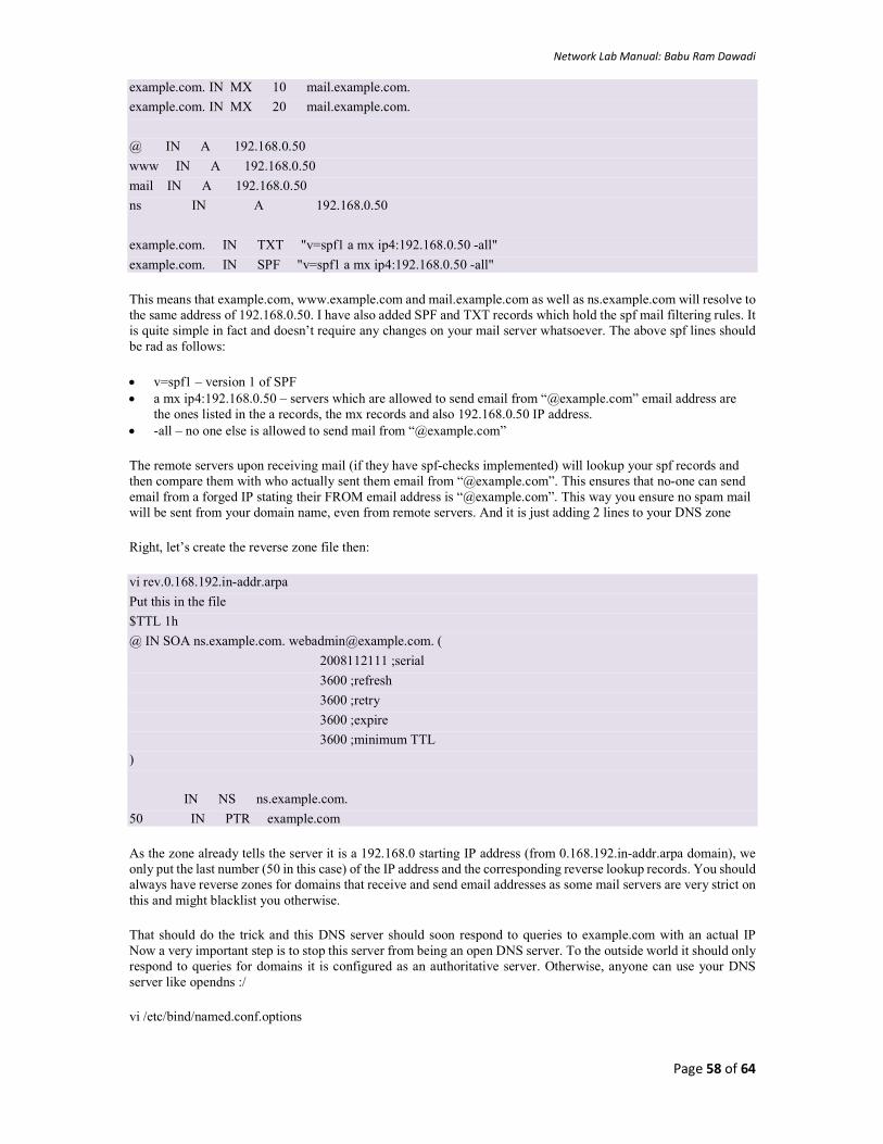
Network Lab Manual: Babu Ram Dawadi
Page 58 of 64
example.com. IN MX 10 mail.example.com.
example.com. IN MX 20 mail.example.com.
@ IN A 192.168.0.50
www IN A 192.168.0.50
mail IN A 192.168.0.50
ns IN A 192.168.0.50
example.com. IN TXT "v=spf1 a mx ip4:192.168.0.50 -all"
example.com. IN SPF "v=spf1 a mx ip4:192.168.0.50 -all"
This means that example.com, www.example.com and mail.example.com as well as ns.example.com will resolve to the same address of 192.168.0.50. I have also added SPF and TXT records which hold the spf mail filtering rules. It is quite simple in fact and doesn’t require any changes on your mail server whatsoever. The above spf lines should be rad as follows:
v=spf1 – version 1 of SPF a mx ip4:192.168.0.50 – servers which are allowed to send email from “@example.com” email address are
the ones listed in the a records, the mx records and also 192.168.0.50 IP address. -all – no one else is allowed to send mail from “@example.com”
The remote servers upon receiving mail (if they have spf-checks implemented) will lookup your spf records and then compare them with who actually sent them email from “@example.com”. This ensures that no-one can send email from a forged IP stating their FROM email address is “@example.com”. This way you ensure no spam mail will be sent from your domain name, even from remote servers. And it is just adding 2 lines to your DNS zone
Right, let’s create the reverse zone file then:
vi rev.0.168.192.in-addr.arpa
Put this in the file
$TTL 1h
@ IN SOA ns.example.com. [email protected]. (
2008112111 ;serial
3600 ;refresh
3600 ;retry
3600 ;expire
3600 ;minimum TTL
)
IN NS ns.example.com.
50 IN PTR example.com
As the zone already tells the server it is a 192.168.0 starting IP address (from 0.168.192.in-addr.arpa domain), we only put the last number (50 in this case) of the IP address and the corresponding reverse lookup records. You should always have reverse zones for domains that receive and send email addresses as some mail servers are very strict on this and might blacklist you otherwise.
That should do the trick and this DNS server should soon respond to queries to example.com with an actual IP Now a very important step is to stop this server from being an open DNS server. To the outside world it should only respond to queries for domains it is configured as an authoritative server. Otherwise, anyone can use your DNS server like opendns :/
vi /etc/bind/named.conf.options
Network Lab Manual: Babu Ram Dawadi
Page 59 of 64
# at the end of the file, just above the enclosure "};" which ends the options part, insert this line # this is assuming you want to allow all lookups from your internal network # and that your internal network is 192.168.24.0/24 allow-recursion { 127.0.0.1; 192.168.24.0/24; };
Restart BIND and do some tests:
# restart bind name server (named)
/etc/init.d/bind9 restart
# if that hangs, ctrl+c the restart. Then run the below 2 commands:
NMD=`ps -A |grep named |grep -v grep |cut -d " " -f 1`; kill -9 $NMD
/etc/init.d/bind9 start
# test new configuration. you should get your 192.168.0.50
dig @localhost example.com
dig @localhost -x 192.168.0.50
# configure machine to use our DNS server as the main one
vi /etc/resolv.conf
# add the below line as the first nameserver entry
nameserver 127.0.0.1
# save the file, no need to restart anything
One final test:
dig example.com
dig -x 192.168.0.50
And we are done. BIND is configured and setup to serve example.com domain. Now you should login to your DNS provider and point the name servers to your server if you want to handle DNS resolution for your domain. If you want to have your DNS server to actually respond you will need to open port 53 UDP and TCP to the internet (as DNS listens on these ports). If you followed my manual on setting up your sshdfilter and firewall, then to open port 53, do this:
iptables -I INPUT -p udp -m udp --dport 53 -j ACCEPT
iptables -I INPUT -p tcp -m tcp --dport 53 -j ACCEPT
iptables-save > /etc/iptables-rules
DHCP Communication Processes
DHCP clients and servers go through a series of exchanges in the process of assigning IP addresses and other network settings. They follow these message types, in order:
First, the client broadcasts a DHCPDiscover message designed to locate a DHCP server and suggest values for the network address and lease duration.
Second, one or more DHCP servers respond with a DHCPOffer, which offers configuration information for the client.
The client then broadcasts a DHCPRequest message to, by default, the nearest DHCP server. This accepts the offered configuration information.
The server then transmits either a DHCPAck or a DHCPNACK message. The DHCPAck confirms a DHCP client's IP address; the DHCPNack declines the client's request.
A client might also transmit a DCHPDecline if it senses that an offered address is already in use. This declines an offered IP address. In this case, the client will have to start the process all over again.
A DHCP client will send a DHCPRelease to relinquish its IP address and end its lease. This request is sent to the DHCP server that issued the lease.
A client can also send a DHCPInform message requesting local configuration information only.
Network Lab Manual: Babu Ram Dawadi
Page 60 of 64
Initial Lease Request
These clients may be new to a network or subnet, or their lease expired after being unable to renew. The initial lease request follows this process:
1. First, the client will seek a DHCP server by broadcasting a DHCPDiscover request. It will wait one second for a response. If it does not receive one, it will rebroadcast its request at intervals of 9, 13, and 16 seconds, with a variable between 0 milliseconds and 1 second. If it cannot reach a DHCP server, it will create an ad-hoc address called an Automatic Private IP Addressing (APIPA) while continuing to broadcast DHCPDiscover requests every 5 minutes. APIPA addresses are IP addresses starting with 169.254.
2. If the client succeeds in finding the DHCP server responsible for its subnet, it answers with a DCHPOffer message, which offers an IP address. Often, more than one server will be able to respond. The server(s) will temporarily reserve the IP address in anticipation of acceptance.
3. When the client receives the DHCP offer or offers, it will choose one and accept it by broadcasting a DHCPRequest. By default, the client will accept the offer of the DHCP server closest to it. Since it is a broadcast, all other servers will know that the client has accepted one of the offers.
4. The DHCP server creates a lease for the address it offered, makes the appropriate changes to its database of available and leased IP addresses, and confirms the IP address assignment with a DHCPAck message.
Lease Renewals
When a DHCP client powers on or connects to the network, it will confirm that it can continue to use its currently
assigned address. If so, the lease is renewed and the expiration date extended. If not, they will try to renew after 50
percent of the lease time has expired. This renewal time value is referred to as T1.
If the T1 attempt fails, the client will try again after 87.5% of the lease has expired. If unsuccessful, it will broadcast
a DHCPDiscover request to receive an IP address from any DHCP server on its network. This binding time value is
referred to as T2.
DHCP renewals use a two-message communication process. A DHCP client makes a request to renew its current
address by sending a DCHPRequest for the renewal of the lease it currently holds. When the server receives the
client's request, it sends a DHCPAck to confirm that the DCHP lease and any DCHP options have been updated.
This information includes a new expiration date for the lease.
If a client cannot reach a DHCP server before its lease expires, it will attempt to acquire a new IP address through
the Initial Release process.
dhcpd.conf File
You can define your server configuration parameters in the dhcpd.conf file which may be located in the /etc the /etc/dhcpd or /etc/dhcp3 directories depending on your version of Linux.
Note: The skeleton dhcp.conf file that is created when you install the package may vary in its completeness. In Ubuntu / Debian, the skeleton dhcpd.conf file is extensive with most of the commands deactivated with a # sign at the beginning. In Fedora / RedHat / CentOS an extensive sample is also created with activated commands. It is found in the following location which you can always use as a guide.
/usr/share/doc/dhcp*/dhcpd.conf.sample
Note: The dhcpd.conf configuration file formats in Debian / Ubuntu and Redhat / Fedora are identical.
The main DHCP configuration file should be located at /etc/dhcpd.conf, however it is sometimes missing. This is a configuration safeguard to stop users from accidentally starting a DHCP server without fully configuring its details. Having any unplanned DHCP servers operating on a network can result in major network problems. Therefore the administrator must create the configuration before implementing its services, a physical task to reduce error (some distributions may have the file available).

Network Lab Manual: Babu Ram Dawadi
Page 61 of 64
[bash]# vi /etc/dhcpd.conf
The following configuration file is an example for a typical home / small office network.
Be sure to change parameters to suit your network and domain name.
# DHCP Server Config File
ddns-update-style none;
ignore client-updates;
lease-file-name "/var/lib/dhcpd/dhcpd.leases";
authoritative;
option domain-name "example.com";
default-lease-time 86400; # 24 hours
max-lease-time 172800; # 48 hours
subnet 192.168.1.0 netmask 255.255.255.0 {
option routers 192.168.1.1;
option subnet-mask 255.255.255.0;
option broadcast-address 192.168.1.255;
option domain-name-servers 192.168.1.1;
option ntp-servers 192.168.1.1;
option netbios-name-servers 192.168.1.1;
range 192.168.1.101 192.168.1.200;
}
Setting Fixed Addresses
There may be a time when it is necessary for a workstation to be assigned a fixed address, this can be easily
achieved by setting the following details in the bottom of the /etc/dhcpd.conf file.
host wkstn1 { hardware ethernet 00:0d:62:d7:a0:12; fixed-address 192.168.1.5; }
Setting Daemon Options
The DHCP daemon can be configured with command line options by using the /etc/sysconfig/dhcpd file. For
security, DHCP can be bound to an interface so the allocation of addresses are only available to the private internal
network.
[bash]# vi /etc/sysconfig/dhcpd
Setting this option provides queries and assignment only through this interface.
# Command line options here DHCPDARGS=eth1
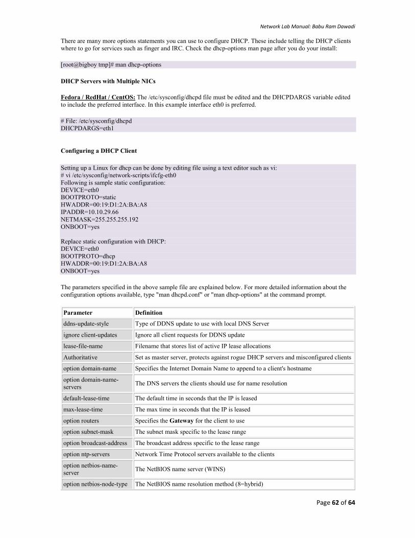
Network Lab Manual: Babu Ram Dawadi
Page 62 of 64
There are many more options statements you can use to configure DHCP. These include telling the DHCP clients where to go for services such as finger and IRC. Check the dhcp-options man page after you do your install:
[root@bigboy tmp]# man dhcp-options
DHCP Servers with Multiple NICs
Fedora / RedHat / CentOS: The /etc/sysconfig/dhcpd file must be edited and the DHCPDARGS variable edited to include the preferred interface. In this example interface eth0 is preferred.
# File: /etc/sysconfig/dhcpd DHCPDARGS=eth1
Configuring a DHCP Client
Setting up a Linux for dhcp can be done by editing file using a text editor such as vi: # vi /etc/sysconfig/network-scripts/ifcfg-eth0 Following is sample static configuration: DEVICE=eth0 BOOTPROTO=static HWADDR=00:19:D1:2A:BA:A8 IPADDR=10.10.29.66 NETMASK=255.255.255.192 ONBOOT=yes Replace static configuration with DHCP: DEVICE=eth0 BOOTPROTO=dhcp HWADDR=00:19:D1:2A:BA:A8 ONBOOT=yes
The parameters specified in the above sample file are explained below. For more detailed information about the configuration options available, type "man dhcpd.conf" or "man dhcp-options" at the command prompt.
Parameter Definition
ddns-update-style Type of DDNS update to use with local DNS Server
ignore client-updates Ignore all client requests for DDNS update
lease-file-name Filename that stores list of active IP lease allocations
Authoritative Set as master server, protects against rogue DHCP servers and misconfigured clients
option domain-name Specifies the Internet Domain Name to append to a client's hostname
option domain-name-servers
The DNS servers the clients should use for name resolution
default-lease-time The default time in seconds that the IP is leased
max-lease-time The max time in seconds that the IP is leased
option routers Specifies the Gateway for the client to use
option subnet-mask The subnet mask specific to the lease range
option broadcast-address The broadcast address specific to the lease range
option ntp-servers Network Time Protocol servers available to the clients
option netbios-name-server
The NetBIOS name server (WINS)
option netbios-node-type The NetBIOS name resolution method (8=hybrid)

Network Lab Manual: Babu Ram Dawadi
Page 63 of 64
Range The range of valid IP addresses available for client offer
Your Task: Study yourself for Web and FTP server installation and configurations on Linux
DHCP configuration on CISCO Router: Consider the following setup
Router(config)# int fa0/0 Router (config-if)#ip address 192.168.10.1 255.255.255.0 Router (config-if)#exit Router (config-if)#ip dhcp pool dhclab Router(dhcp-config)# network 192.168.10.0 255.255.255.0 //network network-number [mask | /prefix-length] Router(dhcp-config)#default-router 192.168.10.1 Router(dhcp-config)#dns-server 192.168.10.2 Router(dhcp-config)# exit Router(config)# ip dhcp excluded-address 192.168.10.1 192.168.10.10 //not in the dhcp pool Router(config)#ip dhcp excluded-address 192.168.10.248 192.168.10.254 //not in the dhcp pool Router(config)#exit Router(config)#wr //set the all PC network configuration to DHCP
Find out:
What is the IP address of PC0, PC1 and PC2 acquired from DHCP?

Network Lab Manual: Babu Ram Dawadi
Page 64 of 64
Final Lab Exam (Test) (Marks: 20)
Consider the following Topology,
1. Configure the DNS and Web server for www.nwlab.com and ftp server.
2. Configure RIP routing for all router
3. Create vlan10 and vlan20 in topology indicated.
4. Show the ping result from PC0 to PC3, PC0 to PC5 and PC7 to PC4
5. Copy the entire configuration to word document with your name and roll-No
6. Create ACL at Router 0, such that traffic from PC7 can’t pass via Switch3.
7. Appear in the necessary VIVA
Good Luck
~O~
References
1. http://www.treca.org/cms/lib01/OH16000157/Centricity/ModuleInstance/202/PT-CreateTopologyInstructorVersion.pdf
2. http://www.computernetworkingnotes.com/ccna-study-guide/basic-concepts-of-frame-relay-explained-in-easy-language.html
3. http://www.cisco.com/c/en/us/support/docs/security/ios-firewall/23602-confaccesslists.html 4. http://websistent.com/how-to-configure-frame-relay-in-cisco-packet-tracer/