A Practical Guide for Resource Monitoring and Control … · 4.9 Audit Log commands ... 5-3 TEC...
220
ibm.com/redbooks A Practical Guide for Resource Monitoring and Control (RMC) Keigo Matsubara Bruno Blanchard Peter Nutt Mamoru Tokuyama Tomoyuki Niijima Configure RMC using the Web-based System Manager Comprehensive examples of the RMC command line interface Practical examples on how to monitor your applications
Transcript of A Practical Guide for Resource Monitoring and Control … · 4.9 Audit Log commands ... 5-3 TEC...

ibm.com/redbooks
A Practical Guide forResource Monitoring and Control (RMC)
Keigo MatsubaraBruno Blanchard
Peter NuttMamoru Tokuyama
Tomoyuki Niijima
Configure RMC using the Web-based System Manager
Comprehensive examples of the RMC command line interface
Practical examples on how to monitor your applications
Front cover

A Practical Guide for Resource Monitoring and Control (RMC)
August 2002
International Technical Support Organization
SG24-6615-00

© Copyright International Business Machines Corporation 2002. All rights reserved.Note to U.S. Government Users Restricted Rights -- Use, duplication or disclosure restricted by GSA ADP ScheduleContract with IBM Corp.
First Edition (August 2002)
This edition applies to AIX 5L Version 5.1 (product number 5765-E61).
Note: Before using this information and the product it supports, read the information in “Notices” on page xi.
Note: This book is based on a pre-GA version of a product and may not apply when the product becomes generally available. We recommend that you consult the product documentation or follow-on versions of this redbook for more current information.

Contents
Figures . . . . . . . . . . . . . . . . . . . . . . . . . . . . . . . . . . . . . . . . . . . . . . . . . . . . . . vii
Tables . . . . . . . . . . . . . . . . . . . . . . . . . . . . . . . . . . . . . . . . . . . . . . . . . . . . . . . . ix
Notices . . . . . . . . . . . . . . . . . . . . . . . . . . . . . . . . . . . . . . . . . . . . . . . . . . . . . . . xiTrademarks . . . . . . . . . . . . . . . . . . . . . . . . . . . . . . . . . . . . . . . . . . . . . . . . . . . xii
Preface . . . . . . . . . . . . . . . . . . . . . . . . . . . . . . . . . . . . . . . . . . . . . . . . . . . . . . xiiiThe team that wrote this redbook. . . . . . . . . . . . . . . . . . . . . . . . . . . . . . . . . . . xiiiBecome a published author . . . . . . . . . . . . . . . . . . . . . . . . . . . . . . . . . . . . . . . xivComments welcome. . . . . . . . . . . . . . . . . . . . . . . . . . . . . . . . . . . . . . . . . . . . . xv
Chapter 1. Introduction . . . . . . . . . . . . . . . . . . . . . . . . . . . . . . . . . . . . . . . . . . 11.1 What is RMC . . . . . . . . . . . . . . . . . . . . . . . . . . . . . . . . . . . . . . . . . . . . . . . . 21.2 The evolution of RMC . . . . . . . . . . . . . . . . . . . . . . . . . . . . . . . . . . . . . . . . . 41.3 Clustered environment . . . . . . . . . . . . . . . . . . . . . . . . . . . . . . . . . . . . . . . . 5
1.3.1 Peer domain . . . . . . . . . . . . . . . . . . . . . . . . . . . . . . . . . . . . . . . . . . . . 61.3.2 Management domain . . . . . . . . . . . . . . . . . . . . . . . . . . . . . . . . . . . . . 7
1.4 RMC software packaging . . . . . . . . . . . . . . . . . . . . . . . . . . . . . . . . . . . . . . 81.4.1 Filesets and packages . . . . . . . . . . . . . . . . . . . . . . . . . . . . . . . . . . . . 91.4.2 Uninstall RMC from your system. . . . . . . . . . . . . . . . . . . . . . . . . . . . 121.4.3 Reinstall RMC on your system . . . . . . . . . . . . . . . . . . . . . . . . . . . . . 12
Chapter 2. Architecture and components . . . . . . . . . . . . . . . . . . . . . . . . . . 152.1 A glance at the architecture. . . . . . . . . . . . . . . . . . . . . . . . . . . . . . . . . . . . 16
2.1.1 RMC clients . . . . . . . . . . . . . . . . . . . . . . . . . . . . . . . . . . . . . . . . . . . . 172.2 Resource, resource class, and attribute . . . . . . . . . . . . . . . . . . . . . . . . . . 19
2.2.1 Resource. . . . . . . . . . . . . . . . . . . . . . . . . . . . . . . . . . . . . . . . . . . . . . 202.2.2 Resource class . . . . . . . . . . . . . . . . . . . . . . . . . . . . . . . . . . . . . . . . . 212.2.3 Attribute . . . . . . . . . . . . . . . . . . . . . . . . . . . . . . . . . . . . . . . . . . . . . . . 21
2.3 Resource managers . . . . . . . . . . . . . . . . . . . . . . . . . . . . . . . . . . . . . . . . . 232.3.1 Event Response resource manager (ERRM) . . . . . . . . . . . . . . . . . . 242.3.2 Audit Log resource manager. . . . . . . . . . . . . . . . . . . . . . . . . . . . . . . 262.3.3 Configuration resource manager. . . . . . . . . . . . . . . . . . . . . . . . . . . . 272.3.4 File system resource manager . . . . . . . . . . . . . . . . . . . . . . . . . . . . . 282.3.5 Host resource manager. . . . . . . . . . . . . . . . . . . . . . . . . . . . . . . . . . . 282.3.6 Sensor resource manager. . . . . . . . . . . . . . . . . . . . . . . . . . . . . . . . . 29
2.4 Expression. . . . . . . . . . . . . . . . . . . . . . . . . . . . . . . . . . . . . . . . . . . . . . . . . 302.5 Condition, response, and action . . . . . . . . . . . . . . . . . . . . . . . . . . . . . . . . 30
© Copyright IBM Corp. 2002. All rights reserved. iii

2.5.1 Condition . . . . . . . . . . . . . . . . . . . . . . . . . . . . . . . . . . . . . . . . . . . . . . 302.5.2 Action . . . . . . . . . . . . . . . . . . . . . . . . . . . . . . . . . . . . . . . . . . . . . . . . 322.5.3 Response . . . . . . . . . . . . . . . . . . . . . . . . . . . . . . . . . . . . . . . . . . . . . 332.5.4 Association between a condition with a response. . . . . . . . . . . . . . . 34
2.6 Directory structure used by RMC . . . . . . . . . . . . . . . . . . . . . . . . . . . . . . . 35
Chapter 3. Quick start: using RMC . . . . . . . . . . . . . . . . . . . . . . . . . . . . . . . 373.1 AIX 5L Version 5.1 Web-based System Manager. . . . . . . . . . . . . . . . . . . 38
3.1.1 Enable remote Web-based System Manager access . . . . . . . . . . . . 403.1.2 Install Web-based System Manager PC client . . . . . . . . . . . . . . . . . 403.1.3 Connect to AIX 5L Version 5.1 system using the PC client . . . . . . . 413.1.4 Connections to multiple hosts . . . . . . . . . . . . . . . . . . . . . . . . . . . . . . 42
3.2 RMC setup procedure . . . . . . . . . . . . . . . . . . . . . . . . . . . . . . . . . . . . . . . . 453.2.1 Basic RMC concepts. . . . . . . . . . . . . . . . . . . . . . . . . . . . . . . . . . . . . 453.2.2 Step one: the Monitoring plug-in . . . . . . . . . . . . . . . . . . . . . . . . . . . . 483.2.3 Step two: the Conditions plug-in . . . . . . . . . . . . . . . . . . . . . . . . . . . . 483.2.4 Monitoring a condition . . . . . . . . . . . . . . . . . . . . . . . . . . . . . . . . . . . . 493.2.5 Viewing events . . . . . . . . . . . . . . . . . . . . . . . . . . . . . . . . . . . . . . . . . 54
3.3 Customizing your RMC configuration . . . . . . . . . . . . . . . . . . . . . . . . . . . . 573.3.1 Properties of a condition . . . . . . . . . . . . . . . . . . . . . . . . . . . . . . . . . . 573.3.2 Monitored resources . . . . . . . . . . . . . . . . . . . . . . . . . . . . . . . . . . . . . 583.3.3 General Condition Properties . . . . . . . . . . . . . . . . . . . . . . . . . . . . . . 613.3.4 Responses to a condition . . . . . . . . . . . . . . . . . . . . . . . . . . . . . . . . . 63
3.4 Creating a new condition or response . . . . . . . . . . . . . . . . . . . . . . . . . . . . 703.4.1 Creating a new condition. . . . . . . . . . . . . . . . . . . . . . . . . . . . . . . . . . 713.4.2 Creating a new response . . . . . . . . . . . . . . . . . . . . . . . . . . . . . . . . . 803.4.3 The /home/remount script . . . . . . . . . . . . . . . . . . . . . . . . . . . . . . . . . 893.4.4 Generating the event. . . . . . . . . . . . . . . . . . . . . . . . . . . . . . . . . . . . . 90
Chapter 4. RMC command line interface . . . . . . . . . . . . . . . . . . . . . . . . . . 934.1 Test environment. . . . . . . . . . . . . . . . . . . . . . . . . . . . . . . . . . . . . . . . . . . . 944.2 Common variables and command flags . . . . . . . . . . . . . . . . . . . . . . . . . . 95
4.2.1 Environment variables. . . . . . . . . . . . . . . . . . . . . . . . . . . . . . . . . . . . 954.2.2 Command flags and pattern match operators . . . . . . . . . . . . . . . . . . 994.2.3 Persistent property value file . . . . . . . . . . . . . . . . . . . . . . . . . . . . . . 106
4.3 A peer domain cluster setup . . . . . . . . . . . . . . . . . . . . . . . . . . . . . . . . . . 1064.3.1 Required filesets . . . . . . . . . . . . . . . . . . . . . . . . . . . . . . . . . . . . . . . 1074.3.2 Preparing your node security . . . . . . . . . . . . . . . . . . . . . . . . . . . . . 1074.3.3 Creating the cluster . . . . . . . . . . . . . . . . . . . . . . . . . . . . . . . . . . . . . 1074.3.4 Bringing the cluster online. . . . . . . . . . . . . . . . . . . . . . . . . . . . . . . . 1084.3.5 Adding a node to the cluster . . . . . . . . . . . . . . . . . . . . . . . . . . . . . . 1094.3.6 Bringing a node online . . . . . . . . . . . . . . . . . . . . . . . . . . . . . . . . . . 1104.3.7 Stopping (offline) a node in the cluster . . . . . . . . . . . . . . . . . . . . . . 110
iv A Practical Guide for Resource Monitoring and Control (RMC)
4.3.8 Removing a node from the cluster . . . . . . . . . . . . . . . . . . . . . . . . . 1114.3.9 Stopping (offline) a cluster . . . . . . . . . . . . . . . . . . . . . . . . . . . . . . . 1114.3.10 Removing a cluster . . . . . . . . . . . . . . . . . . . . . . . . . . . . . . . . . . . . 112
4.4 SRC commands . . . . . . . . . . . . . . . . . . . . . . . . . . . . . . . . . . . . . . . . . . . 1124.4.1 lssrc . . . . . . . . . . . . . . . . . . . . . . . . . . . . . . . . . . . . . . . . . . . . . . . . . 1124.4.2 nlssrc . . . . . . . . . . . . . . . . . . . . . . . . . . . . . . . . . . . . . . . . . . . . . . . . 1134.4.3 Other SRC commands . . . . . . . . . . . . . . . . . . . . . . . . . . . . . . . . . . 113
4.5 RSCT commands . . . . . . . . . . . . . . . . . . . . . . . . . . . . . . . . . . . . . . . . . . 1144.6 RMC commands . . . . . . . . . . . . . . . . . . . . . . . . . . . . . . . . . . . . . . . . . . . 114
4.6.1 lsrsrc . . . . . . . . . . . . . . . . . . . . . . . . . . . . . . . . . . . . . . . . . . . . . . . . 1154.6.2 lsrsrcdef. . . . . . . . . . . . . . . . . . . . . . . . . . . . . . . . . . . . . . . . . . . . . . 1194.6.3 refrsrc . . . . . . . . . . . . . . . . . . . . . . . . . . . . . . . . . . . . . . . . . . . . . . . 121
4.7 Sensor commands . . . . . . . . . . . . . . . . . . . . . . . . . . . . . . . . . . . . . . . . . 1224.7.1 lssensor. . . . . . . . . . . . . . . . . . . . . . . . . . . . . . . . . . . . . . . . . . . . . . 1234.7.2 mksensor. . . . . . . . . . . . . . . . . . . . . . . . . . . . . . . . . . . . . . . . . . . . . 1254.7.3 chsensor . . . . . . . . . . . . . . . . . . . . . . . . . . . . . . . . . . . . . . . . . . . . . 1254.7.4 rmsensor . . . . . . . . . . . . . . . . . . . . . . . . . . . . . . . . . . . . . . . . . . . . . 125
4.8 ERRM commands . . . . . . . . . . . . . . . . . . . . . . . . . . . . . . . . . . . . . . . . . . 1264.8.1 Location concepts . . . . . . . . . . . . . . . . . . . . . . . . . . . . . . . . . . . . . . 1274.8.2 lscondition . . . . . . . . . . . . . . . . . . . . . . . . . . . . . . . . . . . . . . . . . . . . 1274.8.3 lsresponse. . . . . . . . . . . . . . . . . . . . . . . . . . . . . . . . . . . . . . . . . . . . 1324.8.4 lscondresp. . . . . . . . . . . . . . . . . . . . . . . . . . . . . . . . . . . . . . . . . . . . 1344.8.5 mkcondition . . . . . . . . . . . . . . . . . . . . . . . . . . . . . . . . . . . . . . . . . . . 1354.8.6 mkresponse. . . . . . . . . . . . . . . . . . . . . . . . . . . . . . . . . . . . . . . . . . . 1374.8.7 mkcondresp/startcondresp . . . . . . . . . . . . . . . . . . . . . . . . . . . . . . . 1394.8.8 chcondition . . . . . . . . . . . . . . . . . . . . . . . . . . . . . . . . . . . . . . . . . . . 1394.8.9 chresponse . . . . . . . . . . . . . . . . . . . . . . . . . . . . . . . . . . . . . . . . . . . 1414.8.10 stopcondresp/rmcondresp. . . . . . . . . . . . . . . . . . . . . . . . . . . . . . . 1414.8.11 rmcondition/rmresponse . . . . . . . . . . . . . . . . . . . . . . . . . . . . . . . . 141
4.9 Audit Log commands. . . . . . . . . . . . . . . . . . . . . . . . . . . . . . . . . . . . . . . . 1424.10 Additional security configuration . . . . . . . . . . . . . . . . . . . . . . . . . . . . . . 143
4.10.1 Authorization . . . . . . . . . . . . . . . . . . . . . . . . . . . . . . . . . . . . . . . . . 1434.10.2 Remote node access . . . . . . . . . . . . . . . . . . . . . . . . . . . . . . . . . . 147
Chapter 5. Monitoring applications . . . . . . . . . . . . . . . . . . . . . . . . . . . . . . 1515.1 How to monitor DB2 Universal Database . . . . . . . . . . . . . . . . . . . . . . . . 152
5.1.1 Components to be monitored . . . . . . . . . . . . . . . . . . . . . . . . . . . . . 1535.1.2 Configure a DB2 UDB monitor resource . . . . . . . . . . . . . . . . . . . . . 155
5.2 Advanced monitoring. . . . . . . . . . . . . . . . . . . . . . . . . . . . . . . . . . . . . . . . 1565.2.1 Define your own sensor . . . . . . . . . . . . . . . . . . . . . . . . . . . . . . . . . 1565.2.2 Advanced monitoring example . . . . . . . . . . . . . . . . . . . . . . . . . . . . 1605.2.3 Creating your own response . . . . . . . . . . . . . . . . . . . . . . . . . . . . . . 166
5.3 How to send events to Tivoli Enterprise Console . . . . . . . . . . . . . . . . . . 170
Contents v

5.3.1 System environment of TEC . . . . . . . . . . . . . . . . . . . . . . . . . . . . . . 1715.3.2 Create an action script to report to TEC . . . . . . . . . . . . . . . . . . . . . 172
Appendix A. Filesets level information . . . . . . . . . . . . . . . . . . . . . . . . . . . 175RSCT and RMC filesets level. . . . . . . . . . . . . . . . . . . . . . . . . . . . . . . . . . . . . 176Web-based System Manager filesets level . . . . . . . . . . . . . . . . . . . . . . . . . . 177
Appendix B. Useful information. . . . . . . . . . . . . . . . . . . . . . . . . . . . . . . . . 179rsct.core.README . . . . . . . . . . . . . . . . . . . . . . . . . . . . . . . . . . . . . . . . . . . . . 180
Description . . . . . . . . . . . . . . . . . . . . . . . . . . . . . . . . . . . . . . . . . . . . . . . . 180Installation information . . . . . . . . . . . . . . . . . . . . . . . . . . . . . . . . . . . . . . . 180Advisories . . . . . . . . . . . . . . . . . . . . . . . . . . . . . . . . . . . . . . . . . . . . . . . . . 181World Wide Web access information . . . . . . . . . . . . . . . . . . . . . . . . . . . . 183
Perl/Expect installation . . . . . . . . . . . . . . . . . . . . . . . . . . . . . . . . . . . . . . . . . . 184
Abbreviations and acronyms . . . . . . . . . . . . . . . . . . . . . . . . . . . . . . . . . . . 187
Related publications . . . . . . . . . . . . . . . . . . . . . . . . . . . . . . . . . . . . . . . . . . 189IBM Redbooks . . . . . . . . . . . . . . . . . . . . . . . . . . . . . . . . . . . . . . . . . . . . . . . . 189
Other resources . . . . . . . . . . . . . . . . . . . . . . . . . . . . . . . . . . . . . . . . . . . . 189Referenced Web sites . . . . . . . . . . . . . . . . . . . . . . . . . . . . . . . . . . . . . . . . . . 190How to get IBM Redbooks . . . . . . . . . . . . . . . . . . . . . . . . . . . . . . . . . . . . . . . 190
IBM Redbooks collections. . . . . . . . . . . . . . . . . . . . . . . . . . . . . . . . . . . . . 191
Index . . . . . . . . . . . . . . . . . . . . . . . . . . . . . . . . . . . . . . . . . . . . . . . . . . . . . . . 193
vi A Practical Guide for Resource Monitoring and Control (RMC)

Figures
1-1 Overview of AIX cluster architecture . . . . . . . . . . . . . . . . . . . . . . . . . . . . 31-2 Peer domain cluster topology . . . . . . . . . . . . . . . . . . . . . . . . . . . . . . . . . 71-3 Management domain cluster topology . . . . . . . . . . . . . . . . . . . . . . . . . . . 82-1 Detailed relationship between RMC components and clients . . . . . . . . 162-2 Relationship between RMC clients and RMC sub systems . . . . . . . . . . 182-3 Resource managers, resource classes, resources, and attributes . . . . 202-4 Condition, expression, and events . . . . . . . . . . . . . . . . . . . . . . . . . . . . . 322-5 Conditions, responses, and actions . . . . . . . . . . . . . . . . . . . . . . . . . . . . 353-1 AIX 5L Version 5.1 Web-based System Manager . . . . . . . . . . . . . . . . . 393-2 Log On dialog box . . . . . . . . . . . . . . . . . . . . . . . . . . . . . . . . . . . . . . . . . 413-3 The Web-based System Manager window . . . . . . . . . . . . . . . . . . . . . . 423-4 Adding hosts to the management environment . . . . . . . . . . . . . . . . . . . 433-5 Selecting a host to manage . . . . . . . . . . . . . . . . . . . . . . . . . . . . . . . . . . 433-6 Log On window . . . . . . . . . . . . . . . . . . . . . . . . . . . . . . . . . . . . . . . . . . . 443-7 Tiled windows . . . . . . . . . . . . . . . . . . . . . . . . . . . . . . . . . . . . . . . . . . . . 453-8 Condition properties dialog box . . . . . . . . . . . . . . . . . . . . . . . . . . . . . . . 463-9 Selecting the Monitoring plug-in. . . . . . . . . . . . . . . . . . . . . . . . . . . . . . . 483-10 Selecting the Conditions plug-in . . . . . . . . . . . . . . . . . . . . . . . . . . . . . . 493-11 Conditions pop-up window. . . . . . . . . . . . . . . . . . . . . . . . . . . . . . . . . . . 503-12 Edit responses dialog box (before selection) . . . . . . . . . . . . . . . . . . . . . 513-13 Edit responses dialog box (after selection) . . . . . . . . . . . . . . . . . . . . . . 523-14 Monitoring started display . . . . . . . . . . . . . . . . . . . . . . . . . . . . . . . . . . . 533-15 Selecting the Events plug-in . . . . . . . . . . . . . . . . . . . . . . . . . . . . . . . . . 553-16 Events plug-in . . . . . . . . . . . . . . . . . . . . . . . . . . . . . . . . . . . . . . . . . . . . 563-17 Event properties dialog box . . . . . . . . . . . . . . . . . . . . . . . . . . . . . . . . . . 573-18 Displaying the properties of a condition . . . . . . . . . . . . . . . . . . . . . . . . . 583-19 Condition Properties dialog box . . . . . . . . . . . . . . . . . . . . . . . . . . . . . . . 593-20 Condition Properties: Monitored Resources dialog box. . . . . . . . . . . . . 603-21 Selecting an additional resource . . . . . . . . . . . . . . . . . . . . . . . . . . . . . . 613-22 Condition Properties dialog box: changing the rearm expression . . . . . 623-23 Condition Properties dialog box: changing the monitored property . . . . 633-24 Condition Properties: Responses to Condition button . . . . . . . . . . . . . . 643-25 Edit Responses to Condition . . . . . . . . . . . . . . . . . . . . . . . . . . . . . . . . . 653-26 Response Properties dialog box . . . . . . . . . . . . . . . . . . . . . . . . . . . . . . 663-27 Modify Actions dialog box . . . . . . . . . . . . . . . . . . . . . . . . . . . . . . . . . . . 673-28 Modify Action: When in Effect . . . . . . . . . . . . . . . . . . . . . . . . . . . . . . . . 683-29 Modify action: setting the new period. . . . . . . . . . . . . . . . . . . . . . . . . . . 693-30 Modify action: new period addition complete . . . . . . . . . . . . . . . . . . . . . 70
© Copyright IBM Corp. 2002. All rights reserved. vii
3-31 Creating a new condition from the Overview and Tasks plug-in . . . . . . 713-32 New Condition dialog box . . . . . . . . . . . . . . . . . . . . . . . . . . . . . . . . . . . 723-33 New condition: file system resource class . . . . . . . . . . . . . . . . . . . . . . . 733-34 New condition: monitored resources, all file systems . . . . . . . . . . . . . . 743-35 New condition: /work04 file system selected . . . . . . . . . . . . . . . . . . . . . 753-36 New condition: OpState monitored property . . . . . . . . . . . . . . . . . . . . . 763-37 New condition, expressions completed . . . . . . . . . . . . . . . . . . . . . . . . . 773-38 New condition: severity definition. . . . . . . . . . . . . . . . . . . . . . . . . . . . . . 783-39 New condition created . . . . . . . . . . . . . . . . . . . . . . . . . . . . . . . . . . . . . . 793-40 Events panel showing different severity events . . . . . . . . . . . . . . . . . . . 803-41 New response: drop-down menu . . . . . . . . . . . . . . . . . . . . . . . . . . . . . . 813-42 Edit Response: create a response button . . . . . . . . . . . . . . . . . . . . . . . 823-43 New Response dialog box: specifying the name of the response . . . . . 833-44 Add Action dialog box . . . . . . . . . . . . . . . . . . . . . . . . . . . . . . . . . . . . . . 843-45 New response: When in Effect tab. . . . . . . . . . . . . . . . . . . . . . . . . . . . . 853-46 Time in Effect is required . . . . . . . . . . . . . . . . . . . . . . . . . . . . . . . . . . . . 853-47 New response: When in Effect page period defined . . . . . . . . . . . . . . . 863-48 New Response: Attempt remount created . . . . . . . . . . . . . . . . . . . . . . . 873-49 New Response: Attempt remount selected as a response . . . . . . . . . . 883-50 New condition starts monitoring. . . . . . . . . . . . . . . . . . . . . . . . . . . . . . . 893-51 Monitoring: Events window (all events) . . . . . . . . . . . . . . . . . . . . . . . . . 924-1 RMC test environment . . . . . . . . . . . . . . . . . . . . . . . . . . . . . . . . . . . . . . 944-2 The concept of CT_CONTACT . . . . . . . . . . . . . . . . . . . . . . . . . . . . . . . 974-3 The concept of CT_MANAGEMENT_SCOPE . . . . . . . . . . . . . . . . . . . . 984-4 Remote management without a cluster configuration . . . . . . . . . . . . . 1475-1 Relationship between sensor, response, and others . . . . . . . . . . . . . . 1605-2 Test environment with a TEC server . . . . . . . . . . . . . . . . . . . . . . . . . . 1725-3 TEC console sample in summery chart view . . . . . . . . . . . . . . . . . . . . 173
viii A Practical Guide for Resource Monitoring and Control (RMC)

Tables
1-1 Cluster domain characteristics . . . . . . . . . . . . . . . . . . . . . . . . . . . . . . . . . 61-2 Fileset name installed by default . . . . . . . . . . . . . . . . . . . . . . . . . . . . . . . 92-1 Base data types . . . . . . . . . . . . . . . . . . . . . . . . . . . . . . . . . . . . . . . . . . . 212-2 Four groups of resource managers . . . . . . . . . . . . . . . . . . . . . . . . . . . . 232-3 Terms used by ERRM . . . . . . . . . . . . . . . . . . . . . . . . . . . . . . . . . . . . . . 243-1 Values for the new condition . . . . . . . . . . . . . . . . . . . . . . . . . . . . . . . . . 764-1 CT_MANAGEMENT_SCOPE . . . . . . . . . . . . . . . . . . . . . . . . . . . . . . . . 97
© Copyright IBM Corp. 2002. All rights reserved. ix

x A Practical Guide for Resource Monitoring and Control (RMC)

Notices
This information was developed for products and services offered in the U.S.A.
IBM may not offer the products, services, or features discussed in this document in other countries. Consult your local IBM representative for information on the products and services currently available in your area. Any reference to an IBM product, program, or service is not intended to state or imply that only that IBM product, program, or service may be used. Any functionally equivalent product, program, or service that does not infringe any IBM intellectual property right may be used instead. However, it is the user's responsibility to evaluate and verify the operation of any non-IBM product, program, or service.
IBM may have patents or pending patent applications covering subject matter described in this document. The furnishing of this document does not give you any license to these patents. You can send license inquiries, in writing, to: IBM Director of Licensing, IBM Corporation, North Castle Drive Armonk, NY 10504-1785 U.S.A.
The following paragraph does not apply to the United Kingdom or any other country where such provisions are inconsistent with local law: INTERNATIONAL BUSINESS MACHINES CORPORATION PROVIDES THIS PUBLICATION "AS IS" WITHOUT WARRANTY OF ANY KIND, EITHER EXPRESS OR IMPLIED, INCLUDING, BUT NOT LIMITED TO, THE IMPLIED WARRANTIES OF NON-INFRINGEMENT, MERCHANTABILITY OR FITNESS FOR A PARTICULAR PURPOSE. Some states do not allow disclaimer of express or implied warranties in certain transactions, therefore, this statement may not apply to you.
This information could include technical inaccuracies or typographical errors. Changes are periodically made to the information herein; these changes will be incorporated in new editions of the publication. IBM may make improvements and/or changes in the product(s) and/or the program(s) described in this publication at any time without notice.
Any references in this information to non-IBM Web sites are provided for convenience only and do not in any manner serve as an endorsement of those Web sites. The materials at those Web sites are not part of the materials for this IBM product and use of those Web sites is at your own risk.
IBM may use or distribute any of the information you supply in any way it believes appropriate without incurring any obligation to you.
Information concerning non-IBM products was obtained from the suppliers of those products, their published announcements or other publicly available sources. IBM has not tested those products and cannot confirm the accuracy of performance, compatibility or any other claims related to non-IBM products. Questions on the capabilities of non-IBM products should be addressed to the suppliers of those products.
This information contains examples of data and reports used in daily business operations. To illustrate them as completely as possible, the examples include the names of individuals, companies, brands, and products. All of these names are fictitious and any similarity to the names and addresses used by an actual business enterprise is entirely coincidental.
COPYRIGHT LICENSE: This information contains sample application programs in source language, which illustrates programming techniques on various operating platforms. You may copy, modify, and distribute these sample programs in any form without payment to IBM, for the purposes of developing, using, marketing or distributing application programs conforming to the application programming interface for the operating platform for which the sample programs are written. These examples have not been thoroughly tested under all conditions. IBM, therefore, cannot guarantee or imply reliability, serviceability, or function of these programs. You may copy, modify, and distribute these sample programs in any form without payment to IBM for the purposes of developing, using, marketing, or distributing application programs conforming to IBM's application programming interfaces.
© Copyright IBM Corp. 2002. All rights reserved. xi

TrademarksThe following terms are trademarks of the International Business Machines Corporation in the United States, other countries, or both:
AIX®AIX 5L™DB2®DB2 Universal Database™e (logo)®
IBM®pSeries™Redbooks™Redbooks(logo)™RS/6000®
SP™Tivoli®Tivoli Enterprise™Tivoli Enterprise Console®
The following terms are trademarks of other companies:
ActionMedia, LANDesk, MMX, Pentium and ProShare are trademarks of Intel Corporation in the United States, other countries, or both.
Microsoft, Windows, Windows NT, and the Windows logo are trademarks of Microsoft Corporation in the United States, other countries, or both.
Java and all Java-based trademarks and logos are trademarks or registered trademarks of Sun Microsystems, Inc. in the United States, other countries, or both.
C-bus is a trademark of Corollary, Inc. in the United States, other countries, or both.
UNIX is a registered trademark of The Open Group in the United States and other countries.
SET, SET Secure Electronic Transaction, and the SET Logo are trademarks owned by SET Secure Electronic Transaction LLC.
Other company, product, and service names may be trademarks or service marks of others.
xii A Practical Guide for Resource Monitoring and Control (RMC)

Preface
This redbook discusses the capabilities of Resource Monitoring and Control (RMC) that enables you to monitor various resources of your system and create automated responses to changing conditions of those resources.
RMC is provided by the AIX 5L Version 5.1 and later operating systems and is a subset of the functionality available in Reliable Scalable Cluster Technology (RSCT). RSCT provides a set of software components that together support a powerful and flexible environment for clustering systems.
The focus of this redbook is to explain the architecture and components of RMC and its usage by providing with practical examples in several different configurations, including:
� Introduction
� Architecture and components
� Quick start: using RMC
� RMC command line interface
� Monitoring applications
This redbook is an ideal desk side reference for IBM employees, Business Partners, and customer system administrators or technical specialists who exploit RMC to manage IBM ^ pSeries servers running AIX 5L Version 5.1.
The team that wrote this redbookThis redbook was produced by a team of specialists from around the world working at the International Technical Support Organization, Austin Center.
Keigo Matsubara is an advisory IT specialist at the International Technical Support Organization (ITSO), Austin Center. Before joining the ITSO, he worked in the System and Web Solution Center in Japan as a Field Technical Support Specialist (FTSS) for pSeries. He has been working for IBM for ten years.
Bruno Blanchard is a Certified IT Specialist working for IBM France at the IGS Pan-EMEA Infrastructure & Technology group, in La Gaude. He holds an Engineer Degree from Ecole Centrale de Paris and a Master of Science degree from Oregon State University. He has been with IBM since 1983, as a system
© Copyright IBM Corp. 2002. All rights reserved. xiii

engineer for VM and AIX. He is a certified AIX and SP specialist, and his areas of expertise also include pSeries servers and clusters, as well as network management. He is currently working as an architect in projects deploying clusters of IBM RS/6000 SP and IBM ^ pSeries 690 servers.
Peter Nutt is a Senior IT Specialist working in IBM UK for the advanced technical support group. He has 26 years of experience in the IT industry with 14 years working in the UNIX operating system field. He has worked at IBM for two years and his areas of expertise include programming, problem determination, application porting, and real-time systems. This is his second redbook.
Mamoru Tokuyama is an IT Specialist working in the System and Web Solution Center in Japan as a FTSS for pSeries. He holds a certified advanced technical expert of AIX and has more than seven years experience in AIX and SP area. He has been working for IBM for 12 years.
Tomoyuki Niijima is an advisory IT architect in ERM service/BIS/IGS in IBM Japan. He has more than 10 years experience in AIX. This is his second redbook.
Thanks to the following people for their contributions to this project:
International Technical Support Organization, Austin CenterEdson Manoel, Luis Ferreira, Wade Wallace
IBM AustinJulie Craft and Yoichiro Ishii
IBM JapanKenji Matsuo
IBM PoughkeepsieAlice Hackett, Gina Yuan, Joseph Chaky, Marcene Stewart-Hill, Michael Schmidt, Margaret Moran, Mike Stancampiano, Myung Bae, Ning-Wu Wang, Susan Yang, Timothy B Flaherty, Ya-Huey Juan
Thanks to the following organization for their contributions to this project:
IBM Japan Systems Engineering Co., Ltd. Data Systems
Become a published authorJoin us for a two- to six-week residency program! Help write an IBM Redbook dealing with specific products or solutions, while getting hands-on experience
xiv A Practical Guide for Resource Monitoring and Control (RMC)

with leading-edge technologies. You'll team with IBM technical professionals, Business Partners and/or customers.
Your efforts will help increase product acceptance and customer satisfaction. As a bonus, you'll develop a network of contacts in IBM development labs, and increase your productivity and marketability.
Find out more about the residency program, browse the residency index, and apply online at:
ibm.com/redbooks/residencies.html
Comments welcomeYour comments are important to us!
We want our Redbooks to be as helpful as possible. Send us your comments about this or other Redbooks in one of the following ways:
� Use the online Contact us review redbook form found at:
ibm.com/redbooks
� Send your comments in an Internet note to:
� Mail your comments to:
IBM Corporation, International Technical Support OrganizationDept. JN9B Building 003 Internal Zip 283411400 Burnet RoadAustin, Texas 78758-3493
Preface xv

xvi A Practical Guide for Resource Monitoring and Control (RMC)

Chapter 1. Introduction
Resource Monitoring and Control (RMC) is a function that gives you the ability to monitor the state of system resources and respond when predefined thresholds are crossed, so that you can perform many routine tasks automatically.
In AIX 5L Version 5.1 and later, RMC is a no charge feature installed by default upon the operating system installation; you can use RMC on a stand-alone system immediately after the installation to monitor your systems.
This chapter includes the following sections:
� Section 1.1, “What is RMC” on page 2
� Section 1.2, “The evolution of RMC” on page 4
� Section 1.3, “Clustered environment” on page 5
� Section 1.4, “RMC software packaging” on page 8
1
© Copyright IBM Corp. 2002. All rights reserved. 1
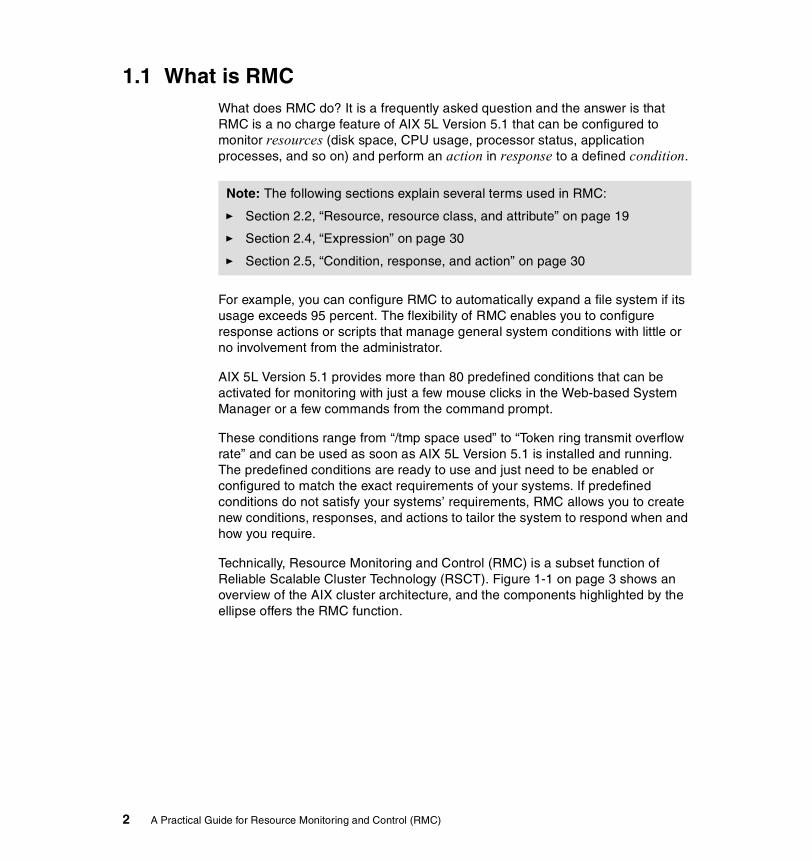
1.1 What is RMCWhat does RMC do? It is a frequently asked question and the answer is that RMC is a no charge feature of AIX 5L Version 5.1 that can be configured to monitor resources (disk space, CPU usage, processor status, application processes, and so on) and perform an action in response to a defined condition.
For example, you can configure RMC to automatically expand a file system if its usage exceeds 95 percent. The flexibility of RMC enables you to configure response actions or scripts that manage general system conditions with little or no involvement from the administrator.
AIX 5L Version 5.1 provides more than 80 predefined conditions that can be activated for monitoring with just a few mouse clicks in the Web-based System Manager or a few commands from the command prompt.
These conditions range from “/tmp space used” to “Token ring transmit overflow rate” and can be used as soon as AIX 5L Version 5.1 is installed and running. The predefined conditions are ready to use and just need to be enabled or configured to match the exact requirements of your systems. If predefined conditions do not satisfy your systems’ requirements, RMC allows you to create new conditions, responses, and actions to tailor the system to respond when and how you require.
Technically, Resource Monitoring and Control (RMC) is a subset function of Reliable Scalable Cluster Technology (RSCT). Figure 1-1 on page 3 shows an overview of the AIX cluster architecture, and the components highlighted by the ellipse offers the RMC function.
Note: The following sections explain several terms used in RMC:
� Section 2.2, “Resource, resource class, and attribute” on page 19
� Section 2.4, “Expression” on page 30
� Section 2.5, “Condition, response, and action” on page 30
2 A Practical Guide for Resource Monitoring and Control (RMC)
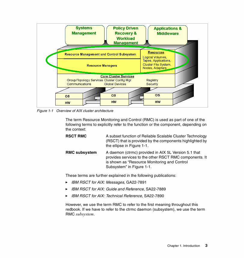
Figure 1-1 Overview of AIX cluster architecture
The term Resource Monitoring and Control (RMC) is used as part of one of the following terms to explicitly refer to the function or the component, depending on the context:
RSCT RMC A subset function of Reliable Scalable Cluster Technology (RSCT) that is provided by the components highlighted by the ellipse in Figure 1-1.
RMC subsystem A daemon (ctrmc) provided in AIX 5L Version 5.1 that provides services to the other RSCT RMC components. It is shown as “Resource Monitoring and Control Subsystem” in Figure 1-1.
These terms are further explained in the following publications:
� IBM RSCT for AIX: Messages, GA22-7891
� IBM RSCT for AIX: Guide and Reference, SA22-7889
� IBM RSCT for AIX: Technical Reference, SA22-7890
However, we use the term RMC to refer to the first meaning throughout this redbook. If we have to refer to the ctrmc daemon (subsystem), we use the term RMC subsystem.
Chapter 1. Introduction 3

1.2 The evolution of RMCTechnically, Resource Monitoring and Control (RMC) is a subset of Reliable Scalable Cluster Technology (RSCT). The functions provided by RSCT were historically known as the High Availability (HA) components of Parallel System Support Program (PSSP), which is a separately purchase-able software product. PSSP is used on the RS/6000 Scalable Parallel (SP) and the IBM ^ Cluster 1600.
The initial use of PSSP was for high performance computing systems using IBM RS/6000 Scalable Parallel (SP) systems, where the only way to satisfy the computing (or I/O) requirement was to exploit parallelism and spread the workload over multiple systems. The PSSP suite includes a number of modules, and together, these modules have the functionality to provide a set of high availability services and facilities ideally suited for building and maintaining large configurations of servers. Following the initial use of PSSP in the scientific computing area, it became apparent that this capability could be used to satisfy the growing requirements in the commercial market place and, through time, modules that proved to be useful in general computing were migrated into standard tools, such as RMC, to be used on any pSeries servers. In contrast, however, SP specific functionality has been retained within PSSP.
Following the evolution path discussed earlier, it can be seen that while RMC is a new facility in AIX 5L Version 5.1, the functionality has been previously available through PSSP and the RSCT components, and the major difference in AIX 5L Version 5.1 is the exposure of the control mechanisms to the users.
When associated with AIX Version 4, PSSP included RSCT Version 1.2.1 as separate filesets to provide the required cluster functionality.
Starting with AIX 5L Version 5.1, RSCT is no longer included in a separate software product, and is included in the operating system as a standard feature. If PSSP is installed, the RSCT provided by AIX 5L Version 5.1 is used for cluster operations.
Because of the history of RSCT, all the components, including Topology Service (TS), Group Service (GS), and Event Monitoring (HAEM), provided by the former versions of PSSP, which include RSCT, have been well documented in many IBM publications in several years. In this context, Topology Service and Group Service are as follows:
Topology Services A distributed subsystem of RSCT that provides node reachability, adapter status information, and a reliable messaging service to other high availability subsystems.
4 A Practical Guide for Resource Monitoring and Control (RMC)

Group Services A subsystem of RSCT that provides a distributed synchronization and coordination service to other high availability subsystems.
You may be interested in RSCT architecture and user interface, because RMC uses TS and GS. We recommend you refer to the following IBM Redbooks for further detail about RSCT:
� GPFS on AIX Clusters: High Performance FIle System Administration Simplified, SG24-6035
� PSSP Version 3 Survival Guide, SG24-5344
� RS/6000 SP Cluster: The Path to Universal Clustering, SG24-5374
� RSCT Group Services: Programming Cluster Applications, SG24-5523
1.3 Clustered environmentRMC is capable of working in a stand-alone1 or clustered environment. In AIX 5L Version 5.1, nodes in a cluster may be configured for either of the following cluster domains:
� Peer domain
� Management domain
The general difference between them is the relationship between the nodes. In a peer domain, all nodes are considered equal and any node can monitor and control (or be monitored and controlled) by any other node. In a management domain, a management node is aware of all nodes it is managing but the nodes themselves know nothing of each other.
Except for the fact that the GUI and CLI must run from the management server in a management domain, the functionality between the two domain types (as well as a stand-alone system) is identical.
Please refer to Table 1-1 on page 6 for further detailed differences between the two domain types.
1 If you use RMC on a stand-alone system, you do not need to perform any cluster configuration.
Chapter 1. Introduction 5
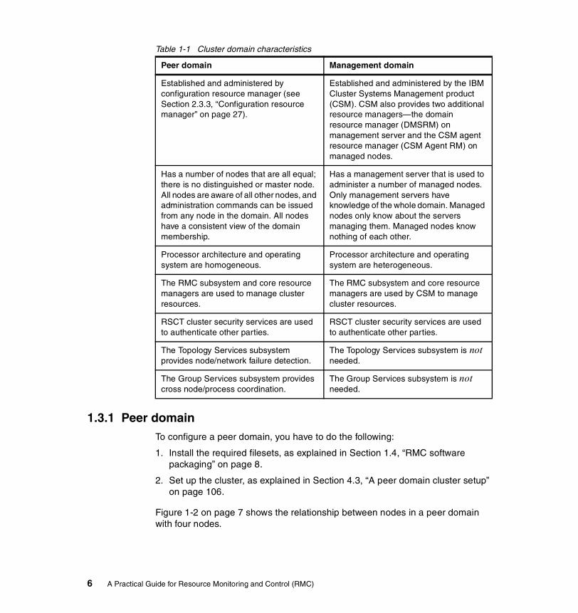
Table 1-1 Cluster domain characteristics
1.3.1 Peer domainTo configure a peer domain, you have to do the following:
1. Install the required filesets, as explained in Section 1.4, “RMC software packaging” on page 8.
2. Set up the cluster, as explained in Section 4.3, “A peer domain cluster setup” on page 106.
Figure 1-2 on page 7 shows the relationship between nodes in a peer domain with four nodes.
Peer domain Management domain
Established and administered by configuration resource manager (see Section 2.3.3, “Configuration resource manager” on page 27).
Established and administered by the IBM Cluster Systems Management product (CSM). CSM also provides two additional resource managers—the domain resource manager (DMSRM) on management server and the CSM agent resource manager (CSM Agent RM) on managed nodes.
Has a number of nodes that are all equal; there is no distinguished or master node. All nodes are aware of all other nodes, and administration commands can be issued from any node in the domain. All nodes have a consistent view of the domain membership.
Has a management server that is used to administer a number of managed nodes. Only management servers have knowledge of the whole domain. Managed nodes only know about the servers managing them. Managed nodes know nothing of each other.
Processor architecture and operating system are homogeneous.
Processor architecture and operating system are heterogeneous.
The RMC subsystem and core resource managers are used to manage cluster resources.
The RMC subsystem and core resource managers are used by CSM to manage cluster resources.
RSCT cluster security services are used to authenticate other parties.
RSCT cluster security services are used to authenticate other parties.
The Topology Services subsystem provides node/network failure detection.
The Topology Services subsystem is not needed.
The Group Services subsystem provides cross node/process coordination.
The Group Services subsystem is not needed.
6 A Practical Guide for Resource Monitoring and Control (RMC)

Figure 1-2 Peer domain cluster topology
1.3.2 Management domainThe management domain is provided for use by the IBM Cluster Systems Management (CSM) product,2 but the operation and capabilities of RMC are the same as the peer domain. At the time of writing this redbook, this mode is only used with CSM.
In a management domain, nodes are managed by a management server.3 The management server is aware of all the nodes it manages and all managed nodes are aware of their management server. However, the managed nodes know nothing about each other.
Figure 1-3 on page 8 shows the relationship between nodes in a management domain.
RMC
Cluster Node 1
RMC
Cluster Node 2
RMC
Cluster Node 4
RMC
Cluster Node 3
2 At the time of writing this redbook, the CSM product is available on the Linux operating system only.3 The management server can be a cluster node at the same time.
Chapter 1. Introduction 7

Figure 1-3 Management domain cluster topology
For further information about CSM, please refer to Linux Clustering with CSM and GPFS, SG24-6601.
1.4 RMC software packagingThe RMC components4 required for a stand-alone configuration are installed automatically upon the AIX 5L Version 5.1 installation by default; therefore, once the AIX 5L Version 5.1 installation is complete, RMC will be active and ready to be used. However, no resources will be monitored or controlled until you have configured the system to do so.
For systems that do not require cluster operation, no further filesets are required. If you are creating a peer domain cluster on an AIX 5L Version 5.1 system, you must install the following three filesets in addition to those filesets installed by default:
� rsct.basic.rte
� rsct.compat.basic.rte
� rsct.compat.clients.rte
RMC
Cluster node 1
RMC
Cluster node 2
RMC
Cluster node 3
RMC
ManagementServer
4 We recommend that you apply the latest fileset updates even if you use RMC in a stand-alone environment only.
8 A Practical Guide for Resource Monitoring and Control (RMC)

1.4.1 Filesets and packagesUpon installation of AIX 5L Version 5.1, the filesets5 shown in Table 1-2 are installed by default.
Table 1-2 Fileset name installed by default
These fileset names are included in the system bundle file /usr/sys/inst.data/sys_bundles/MIN_BOS.autoi, and are to be installed upon installation of AIX 5L Version 5.1, as shown in the following example:
# pwd/usr/sys/inst.data/sys_bundles# grep -i rsct *MIN_BOS.autoi:I:rsct.core.rmcMIN_BOS.autoi:I:rsct.core.srMIN_BOS.autoi:I:rsct.core.errmMIN_BOS.autoi:I:rsct.core.auditrmMIN_BOS.autoi:I:rsct.core.fsrmMIN_BOS.autoi:I:rsct.core.hostrmMIN_BOS.autoi:I:rsct.core.utilsMIN_BOS.autoi:I:rsct.core.guiMIN_BOS.autoi:I:rsct.core.sec
For cluster configurations in a peer domain (see Section 4.3, “A peer domain cluster setup” on page 106), you need to ensure that the latest rsct.basic.rte
Note: These filesets are included in the AIX 5L Version 5.1 installation media.
5 This list does not contain message catalog filesets, such as rsct.msg.en_US.core.rmc.
Fileset name Description
rsct.core.rmc RSCT Resource Monitoring and Control
rsct.core.sr RSCT Registry
rsct.core.errm RSCT Event Response Resource Manager
rsct.core.auditrm RSCT Audit Log Resource Manager
rsct.core.fsrm RSCT File System Resource Manager
rsct.core.hostrm RSCT Host Resource Manager
rsct.core.utils RSCT Utilities
rsct.core.gui RSCT Graphical User Interface
rsct.core.sec RSCT Security
Chapter 1. Introduction 9
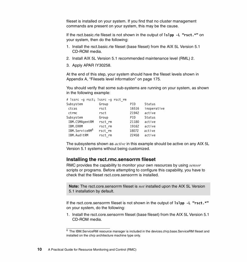
fileset is installed on your system. If you find that no cluster management commands are present on your system, this may be the cause.
If the rsct.basic.rte fileset is not shown in the output of lslpp -L “rsct.*” on your system, then do the following:
1. Install the rsct.basic.rte fileset (base fileset) from the AIX 5L Version 5.1 CD-ROM media.
2. Install AIX 5L Version 5.1 recommended maintenance level (RML) 2.
3. Apply APAR IY30258.
At the end of this step, your system should have the fileset levels shown in Appendix A, “Filesets level information” on page 175.
You should verify that some sub-systems are running on your system, as shown in the following example:
# lssrc -g rsct; lssrc -g rsct_rmSubsystem Group PID Status ctcas rsct 16516 inoperativectrmc rsct 21942 active
Subsystem Group PID StatusIBM.CSMAgentRM rsct_rm 21180 active
IBM.ERRM rsct_rm 19162 active IBM.ServiceRM6 rsct_rm 18072 activeIBM.AuditRM rsct_rm 22458 active
The subsystems shown as active in this example should be active on any AIX 5L Version 5.1 systems without being customized.
Installing the rsct.rmc.sensorrm filesetRMC provides the capability to monitor your own resources by using sensor scripts or programs. Before attempting to configure this capability, you have to check that the fileset rsct.core.sensorrm is installed.
If the rsct.core.sensorrm fileset is not shown in the output of lslpp -L “rsct.*” on your system, do the following:
1. Install the rsct.core.sensorrm fileset (base fileset) from the AIX 5L Version 5.1 CD-ROM media.
6 The IBM.ServiceRM resource manager is included in the devices.chrp.base.ServiceRM fileset and installed on the chrp architecture machine type only.
Note: The rsct.core.sensorrm fileset is not installed upon the AIX 5L Version 5.1 installation by default.
10 A Practical Guide for Resource Monitoring and Control (RMC)

2. Install AIX 5L Version 5.1 recommended maintenance level (RML) 2.
3. Apply IY30258.
By default, the IBM.SensorRM sub-system is not started. It will be started by the RMC subsystem only when resources managed by IBM.SensorRM are referenced. To check if the sub-system is working correctly, execute the lsrsrc IBM.Sensor command, then execute the lssrc commands, as shown in Example 1-1; the IBM.SensorRM subsystem should be active after this operation.
Example 1-1 No IBM.SensorRM sub-system
# lslpp -L | grep sensor rsct.core.sensorrm 2.2.1.10 C F RSCT Sensor Resource Manager# lssrc -g rsct; lssrc -g rsct_rmSubsystem Group PID Status ctrmc rsct 20124 active ctcas rsct 18842 activeSubsystem Group PID Status IBM.ERRM rsct_rm 21442 active IBM.ServiceRM rsct_rm 21702 active IBM.CSMAgentRM rsct_rm 22468 active IBM.AuditRM rsct_rm 4704 activeIBM.SensorRM rsct_rm 20400 active
If it is not still active, do the following:7
1. Stop RMC daemons:
# /usr/sbin/rsct/bin/rmcctrl -z
2. Reconfigure necessary information and start RMC daemons:
# /usr/sbin/rsct/bin/rmcctrl -A
3. Restart the sensor subsystem:
# lsrsrc IBM.Sensor
Then you should see the IBM.SensorRM sub-system is running on your system and ready to use the sensor function.
For further information about sensor, see the following sections:
� Section 4.7, “Sensor commands” on page 122
� Section 5.2, “Advanced monitoring” on page 156
7 This step will update the configuration database to enable IBM.SensorRM.
Chapter 1. Introduction 11

1.4.2 Uninstall RMC from your systemIn some circumstances, you may want to uninstall all the RMC filesets. For example, if you are setting up an AIX system that is directly connected to the Internet and installed with a firewall software, you might be requested to close unused TCP/IP ports and to remove all the files, which are not necessary by this installation.
To remove all the RMC filesets, execute the following command:
# installp -ug rsct.*
The following filesets, which are depending on RMC, are also uninstalled at the same time:
bos.clvm.enh 5.1.0.10
csm.client 1.1.0.1
devices.chrp.base.ServiceRM 1.1.0.0
The command also remove all files and directories under the /var/ct directory.
1.4.3 Reinstall RMC on your systemTo reinstall all the RMC filesets, do the following:
1. Install the following filesets from the AIX 5L Version 5.1 CD-ROM media:
– rsct.core.rmc– rsct.core.sr– rsct.core.errm– rsct.core.auditrm– rsct.core.fsrm– rsct.core.hostrm– rsct.core.utils– rsct.core.gui– rsct.core.sec– rsct.compat.*– csm.client– devices.chrp.base.ServiceRM
Note: We strongly recommend that you do not uninstall RMC from your system, unless you understand what you are going to do and have a strong reason to do so, because some AIX features, such as Service Focal Point, depend on RMC. If you want to turn off TCP port 657 for use by the RMC subsystem, you can execute rmcctrl -P, although it also prevents AIX features relying on RMC from correctly working.
12 A Practical Guide for Resource Monitoring and Control (RMC)

2. Install AIX 5L Version 5.1 recommended maintenance level (RML) 2.
If applying of the 2.2.0.10 level of the rsct.core.sr fileset should fail, then run the command again.
3. Apply IY30258.
Chapter 1. Introduction 13

14 A Practical Guide for Resource Monitoring and Control (RMC)

Chapter 2. Architecture and components
This chapter briefly explains the architecture and the components of Resource Monitoring and Control (RMC) and provides you with the background information you need to quickly set up the monitoring functions on a stand-alone pSeries server or a cluster of pSeries servers.
To explain the architecture and the components, this chapter includes the following six sections:
� Section 2.1, “A glance at the architecture” on page 16
� Section 2.2, “Resource, resource class, and attribute” on page 19
� Section 2.3, “Resource managers” on page 23
� Section 2.4, “Expression” on page 30
� Section 2.5, “Condition, response, and action” on page 30
� Section 2.6, “Directory structure used by RMC” on page 35
2
© Copyright IBM Corp. 2002. All rights reserved. 15

2.1 A glance at the architectureResource Monitoring and Control (RMC) is a subset of Reliable Scalable Cluster Technology (RSCT), where the CT in RSCT means Cluster Technology. Although you can also use RMC to monitor resources on a stand-alone pSeries, the architecture allows the following functions to be supported on clusters:
� Provide single monitoring and management infrastructure for clusters.
� Provide global access to subsystems and resources throughout the cluster.
� Support operations for configuring, monitoring, and controlling all cluster resources by RMC clients.
� Encapsulate all resource dependent operations.
� Provide a common access control mechanism across all resources.
� Support integration with other subsystems to achieve the highest levels of availability.
To support these functions, the structure of the RSCT Resource Monitoring and Control is not simple, as shown in Figure 2-1.
Figure 2-1 Detailed relationship between RMC components and clients
RMC Daemon
RMgrApiSDK C++RMgrApiSDK C++
Registry API
RMgrApiSDK C++
Registry API
RMgrApiSDK C++
Registry API
RMgrApiSDK C++
Registry API
Host IBM.HostIBM.ProcessorIBM.PagingDeviceIBM.PhysicalVolumeIBM.ProgramIBM.TokenRingDeviceIBM.EthernetDeviceIBM.FDDIDeviceIBM.ATMDevice
Audit IBM.AuditLogIBM.AuditLogTemplate
FilesystemIBM.Jfs
EventResponseIBM.ConditionIBM.EventResponseIBM.AssociationResource
Managers RMCAPI
Registry Commands: lssr, lssrtbl, mksrtbl..
RMC API
RMC Commands: lsrsrc, mkrsrc, ...
RMC API
WebSM Server
RMCJNI
WebSMClient
(local or remote)
Monitoring Plugin
CU API
CU Commands: lsclcfg, ...
Trace API
Trace Commands: rpttr
Security API
Perl-to-C
Security API
ProtocolUtils
(local or remote)
Configuration database
IBM.FileSystem
16 A Practical Guide for Resource Monitoring and Control (RMC)

The purpose of this redbook is not to describe the technical internal implementation specifics of RMC; therefore we briefly explain Figure 2-1 on page 16 in the following list:
� The RMC subsystem is the core of RSCT Resource Monitoring and Control. It is a generic component that provides a scalable and reliable backbone to its clients with an interface to resources. It has no knowledge of resource implementations, characteristics, or features. The RMC subsystem therefore delegates to resource managers the actual execution of the actions the clients ask to perform.
� The RMC subsystem and RMC clients (see Section 2.1.1, “RMC clients” on page 17) need not be in the same node. RMC provides a distributed service to its clients. The RMC clients can connect to the RMC daemon either locally or remotely using the RMC API (Resource Monitoring and Control application user interface).
� The RMC subsystem and the Resource Managers (see Section 2.3, “Resource managers” on page 23) it interacts with need not be in the same node. If they are on different nodes, the RMC subsystem will interact with the RMC subsystem located locally on the same node as the resource managers, then the local RMC daemon will forward the request between them.
� Each resource manager is instantiated as one AIX process. To avoid the multiplication of processes, a resource manager can handle several resource classes.
� Many commands of the command line interface are Korn shell or Perl scripts: the end-user can have a look at them and use them as samples for writing his own commands. This will be explained in Chapter 4, “RMC command line interface” on page 93.
For further information about the architecture of RMC, please refer to the following publications:
� IBM RSCT for AIX: Guide and Reference, SA22-7889
� IBM RSCT for AIX: Technical Reference, SA22-7890
2.1.1 RMC clientsAlthough there are several RMC client implementations available, we explain the following two types of interface8 only for RMC clients in this redbook:
� Command line interface (CLI)
� Graphical user interface (GUI)
8 You cannot use SMIT to interact with RMC.
Chapter 2. Architecture and components 17

Throughout this redbook, we refer to both the interfaces as RMC clients. Figure 2-2 illustrates the relationship between the RMC subsystem and its clients. A RMC command line client can access all the resources within a cluster locally (A) and remotely (B). A RMC GUI (WebSM) client also can access all the resources within a cluster locally (D) and remotely (C), but the access path is different between these two interfaces.
Figure 2-2 Relationship between RMC clients and RMC sub systems
Command line interface (CLI)The RMC command line interface is comprised of more than 50 commands: some components, such as Audit Log resource manager, have only two commands, while others, such as Event Response resource manager, have 15 commands.
Most RMC commands provide you with a similar look and feel. Many commands have optional arguments to instructs, the command same functions. In addition to command optional arguments, RMC defines two environment variables, CT_CONTACT and CT_MANAGEMENT_SCOPE. These variables instruct most9 RMC commands to define their target and scope upon retrieving and setting values among cluster nodes.
Finally, RMC has a concept of Resource Data Input, which is a standardized file format for holding resource properties. Many RMC commands have a -f option that allows the end user to pass arguments to the command through a file
RMC subsystem
WebSM server
RMC client(WebSM)RMC client
(CLI)
RMC subsystem
WebSM server
RMC client(WebSM)
RMC client(CLI)
Node 1 Node 2
RSCT
A B
C
D
Resources and Resource classes
9 The CT_CONTACT and CT_MANAGEMENT_SCOPE environment variables are not necessarily supported by all commands.
18 A Practical Guide for Resource Monitoring and Control (RMC)

instead of typing them on the command line. These files have the same Resource Data Input format for all commands so that the same file can be used for different commands. Two commands (lsrsrcdef and lsactdef) can generate such a file so their output can be used as input for other commands.
Chapter 4, “RMC command line interface” on page 93 contains a number of examples showing how to use RMC commands.
For further information about RMC command line interface, please refer to the IBM RSCT for AIX: Technical Reference, SA22-7890.
Graphical user interface (GUI)The RMC graphical user interface is provided by the Web-based System Manager, as explained in Chapter 3, “Quick start: using RMC” on page 37.
2.2 Resource, resource class, and attributeThis section provides you with the three terms used in RMC: resource, resource class, and attribute, as illustrated in Figure 2-3 on page 20. You have to understand these terms explained in this section before performing any configuration and monitoring tasks using RMC.
Note: Web-based System Manager does not generate the command line history, which can be produced in the smit.script file by SMIT, upon execution of operation tasks, this is because Web-based System Manager directly connects to RMC and does not invoke any commands.
Chapter 2. Architecture and components 19

Figure 2-3 Resource managers, resource classes, resources, and attributes10
2.2.1 ResourceThe resource is a fundamental concept in the RMC architecture. A resource is an abstraction of an instance of a physical or logical entity that provides services to applications or system components. A system or cluster is composed of numerous resources of various types.
For example, the /var and the /tmp file systems are represented as two different resources in RMC.
Each resource has the following characteristics:
� An operational interface that is used by its clients. This interface is the reason for the resource’s existence. For example, the operational interface of a logical volume is the standard open, close, read, and write system calls.
� A set of persistent data values called persistent attributes, which describe the characteristics or configuration of the resource. For example, the file system name, logical volume name, and so on.
10 Although a resource class also has its own attributes, as explained in Section 2.2.2, “Resource class” on page 21, this figure does not show the relationship between a resource class and its attributes on purpose.
resource class A
resource class B
resource A1
resource A2
resource A3
resource An
resource B1
resource Bm
attribute A2a
attribute A2b
attribute A2z
attribute B1a
attribute B1b
attribute B1y
resource class C
resourcemanager X
resourcemanager Y
resource C1 attribute C1a
20 A Practical Guide for Resource Monitoring and Control (RMC)

� A set of dynamic data values called dynamic attributes, which reflect the current state or other measurement values of the resource. For example, the disk block usage of a file system.
� A handle that uniquely identifies the resource within the cluster. This value is unique across time and space and is called a resource handle.
� A set of operations that manipulate the state or configuration of the resource.
2.2.2 Resource classA resource class is a collection of resources that have similar characteristics. The resource class provides descriptive information about the properties and characteristics that are common to any resource within the resource class.
For example, all the file system resources, such as /var and /tmp, belong to the file system resource class in RMC.
Each resource class has the following characteristics:
� Descriptive information about the class and its resources.
� A list of the resource handles for all existing resources within the class.
� A set of persistent data values called persistent attributes that describe or control the operation of the resource class.
� A set of dynamic data values called dynamic attributes. For example, every resource class supports a dynamic attribute that changes whenever the number of resources in the class changes.
� An access control list (ACL) that defines permissions that authorized users have for manipulating or querying the resource class.
� A set of operations to modify or query the resource class.
2.2.3 AttributeA resource class and a resource have several attributes. An attribute has a value and a unique name within the resource class or the resource. The attribute value is stored in the one of the base data types shown in Table 2-1.
Table 2-1 Base data types
Symbolic name Description
CT_INT32 Signed 32-bit integer
CT_UINT32 Unsigned 32-bit integer
CT_INT64 Signed 64-bit integer
Chapter 2. Architecture and components 21

In addition to the base data types, an attribute value can be stored in one of the two aggregate data types: array or structured data (SD). The elements of the aggregate types array and SD are of the basic types, and arrays of SD and SD that contains arrays are also supported. However, SD may not contain SD nor arrays of SD.
A resource attribute is classified into either a public or a private property. The property is used as a hint for the RMC client for whether the attribute is to be presented to general users. Private attributes typically contain information that is not relevant to general users; therefore, the private attributes are hidden by default. However, you can display private attributes by specifying a flag in the command. Web-based System Manager does not support the display or modification of private resource attributes.
Attributes fall into two categories: persistent and dynamic. Each category has a different role, and is used differently by RMC clients.
Persistent attributesFor resources, persistent attributes are configuration parameters and are set either by the resource monitor harvesting real resources, or through the mkrsrc or the chrsrc commands. Persistent attributes define the characteristics of the resource. Examples of persistent attributes are Device Name, IP Address, and so on.
For resource classes, persistent attributes describe or control the operations of the class.
CT_UINT64 Unsigned 64-bit integer
CT_FLOAT32 32-bit floating point
CT_FLOAT64 64-bit floating point
CT_CHAR_PTR Null-terminated string
CT_BINARY_PTR Binary data–arbitrary-length block of data
CT_RSRC_HANDLE_PTR Resource handle–an identifier for a resource that is unique over space and time (20 bytes)
Note: The provided set of attributes is static. You cannot add or remove any attributes from resources or resource classes, except for the sensor resource class.
Symbolic name Description
22 A Practical Guide for Resource Monitoring and Control (RMC)
For the RMC client, the main usage of persistent resources are to specify which resources will be accessed. They are used as filters over the set of managed resources to select those on which the client wants to act.
For example, all the file system resources have the persistent attribute Dev, which is supplied by the file system resource manager and derived from the dev attribute in the /etc/filesystems file for the target file system.
Dynamic attributesDynamic attributes reflect internal states or performance variables of resources and resource classes. For example, all the file system resources have dynamic attributes such as, operational state, % total used, % inode used, and so on.
You generally refer to dynamic attributes to define the monitoring condition of the resource you want to monitor. For example, if you want to monitor a file system resource, you can monitor the disk space usage of the file system.
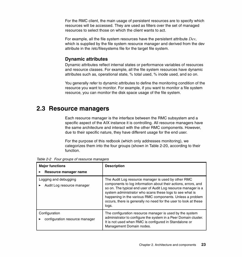
2.3 Resource managersEach resource manager is the interface between the RMC subsystem and a specific aspect of the AIX instance it is controlling. All resource managers have the same architecture and interact with the other RMC components. However, due to their specific nature, they have different usage for the end user.
For the purpose of this redbook (which only addresses monitoring), we categorizes them into the four groups (shown in Table 2-20, according to their function.
Table 2-2 Four groups of resource managers
Major functions
� Resource manager name
Description
Logging and debugging
� Audit Log resource manager
The Audit Log resource manager is used by other RMC components to log information about their actions, errors, and so on. The typical end user of Audit Log resource manager is a system administrator who scans these logs to see what is happening in the various RMC components. Unless a problem occurs, there is generally no need for the user to look at these logs.
Configuration
� configuration resource manager
The configuration resource manager is used by the system administrator to configure the system in a Peer Domain cluster. It is not used when RMC is configured in Standalone or Management Domain nodes.
Chapter 2. Architecture and components 23
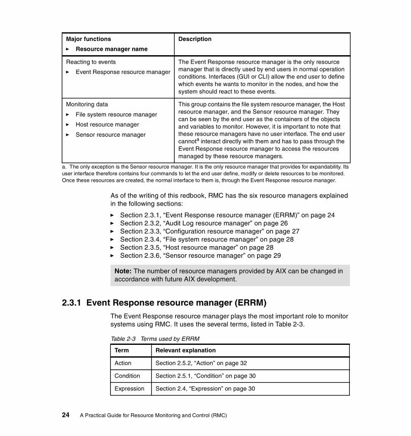
As of the writing of this redbook, RMC has the six resource managers explained in the following sections:
� Section 2.3.1, “Event Response resource manager (ERRM)” on page 24� Section 2.3.2, “Audit Log resource manager” on page 26� Section 2.3.3, “Configuration resource manager” on page 27� Section 2.3.4, “File system resource manager” on page 28� Section 2.3.5, “Host resource manager” on page 28� Section 2.3.6, “Sensor resource manager” on page 29
2.3.1 Event Response resource manager (ERRM)The Event Response resource manager plays the most important role to monitor systems using RMC. It uses the several terms, listed in Table 2-3.
Table 2-3 Terms used by ERRM
Reacting to events
� Event Response resource manager
The Event Response resource manager is the only resource manager that is directly used by end users in normal operation conditions. Interfaces (GUI or CLI) allow the end user to define which events he wants to monitor in the nodes, and how the system should react to these events.
Monitoring data
� File system resource manager
� Host resource manager
� Sensor resource manager
This group contains the file system resource manager, the Host resource manager, and the Sensor resource manager. They can be seen by the end user as the containers of the objects and variables to monitor. However, it is important to note that these resource managers have no user interface. The end user cannota interact directly with them and has to pass through the Event Response resource manager to access the resources managed by these resource managers.
a. The only exception is the Sensor resource manager. It is the only resource manager that provides for expandability. Its user interface therefore contains four commands to let the end user define, modify or delete resources to be monitored. Once these resources are created, the normal interface to them is, through the Event Response resource manager.
Major functions
� Resource manager name
Description
Note: The number of resource managers provided by AIX can be changed in accordance with future AIX development.
Term Relevant explanation
Action Section 2.5.2, “Action” on page 32
Condition Section 2.5.1, “Condition” on page 30
Expression Section 2.4, “Expression” on page 30
24 A Practical Guide for Resource Monitoring and Control (RMC)

The Event Response resource manager provides the system administrator with the ability to define a set of conditions to monitor in the various nodes of the cluster, and to define actions to take in response to these events. The conditions are applied to dynamic properties of any resources of any resource manager in the cluster. The Event Response resource manager provides a simple automation mechanism for implementing event driven actions. Basically, you can do the following:
� Define a condition that is composed of a resource property to be monitored and an expression that is evaluated periodically.
� Define a response that is composed of zero or more actions that consists of a command to be run and controls, such as to when and how the command is to be run.
� Associates one or more responses with a condition and activates the association.
In addition:
� Different users can use the same conditions and responses, and mix and match them to build different monitoring scenarios.
� Many predefined conditions and responses are shipped with the system and can be used as templates for the user who wants to define his own monitoring scenarios.
� Any events that occur and any responses that are run are logged in the audit log. You can look at the audit log to check that the defined conditions were triggered, how the system reacted, and what was the result of the actions.
The Event Response resource manager provides you with both a CLI and a GUI (Web-based System Manager). Because RMC comes with a predefined set of conditions, actions, and responses, we recommend you start by combining some of these into associations using the Web-based System Manager, and to then use the CLI display commands (starting with ls…) to see the results of these combinations.
You can then decide whether you want to use the Web-based System Manager or the CLI. In a stand-alone environment and for setting up limited monitoring of the resources, the Web-based System Manager is the easiest tool to use, unless you are already familiar with the CLI commands and arguments. However, for managing a cluster or developing sophisticated monitoring scenarios, we recommend you to write your own shell scripts calling the CLI commands.
Response Section 2.5.3, “Response” on page 33
Term Relevant explanation
Chapter 2. Architecture and components 25

Examples of the GUI and CLI are presented in Chapter 3, “Quick start: using RMC” on page 37 and Chapter 4, “RMC command line interface” on page 93.
2.3.2 Audit Log resource managerThe Audit Log resource manager provides the other RMC subsystems with an extra logging facility, in addition to the standard AIX errorlog and syslog. It can be seen as a means to trace the various actions that were taken by the RSCT subsystem.
Typically, these subsystems will add entries in the audit log corresponding to their normal behavior or to error cases. Examples of information provided in the audit log are:
� Instances of starting and stopping monitoring
� Events
� Actions taken in response to events
� Results of these actions
� Subsystem errors and monitoring errors
Only subsystems can add records to the audit log; there is no user interface that allows the end user to add entries in the audit log.
Only two actions are offered to you by the Audit Log resource manager:
lsaudrec Lists records in the audit log.
rmaudrec Deletes the specified records in the audit log.
Web-based System Manager provides you with the same function provided by these two CLI commands.
It must be clear to you that the Audit Log is different from the logs that are used by the logevent action. The logevent action cannot be used to add entries in the audit log, and the lsaudrec and rmaudrec commands cannot be used to handle the logs used by the logevent action, which are handled by the AIX alog command. Similarly, the lsaudrec and rmaudrec commands cannot be used to examine either the AIX errorlog or syslog. See Section 4.9, “Audit Log commands” on page 142, for the usage of these commands.
Note: There is no relationship between the RMC audit log function and the AIX security audit function. The RMC audit log does not replace either the AIX errorlog or the syslog.
26 A Practical Guide for Resource Monitoring and Control (RMC)

Because the RMC audit log function is implemented as a resource manager, all actions allowed on RMC resources are also available to handle resources of the Audit Log resource manager. Hence, it is also possible to monitor these resources through the Event Response resource manager features. It is possible, for example, to take an action each time a new entry is created in the Audit Log, by monitoring the RecordsAdded attribute of an AuditLog resource. However, this is not recommended, because it can easily result in an infinite loop of producing events and audit log records each other.
2.3.3 Configuration resource managerThe configuration resource manager can create and manage a peer domain cluster. Therefore, you do not have to use the configuration resource manager to use RMC on a stand-alone server or in a management domain with CSM.
However, if you want to configure peer domains, you have to understand the following concepts:
Peer domain A peer domain is a set of nodes that share the same high availability services (Topology and Group Services). It is also often referred to as an RSCT cluster. From an RMC point of view, all nodes in a peer domain are equivalent, and RMC commands can be executed from any node with any other node (or nodes) as the target. A peer domain can be online or offline, which corresponds to turning on or off the RSCT high availability services.
Node A node can belong to several peer domains: it can be part of the definition of multiple peer domains. However, at one point in time, the node can only belong to at most one online peer domain. Membership to a peer domain is a dynamic feature. A node can be added or removed to existing peer domains.
Security Since remote commands can be executed between nodes in the peer domain, authentication and authorization mechanisms are provided with RMC to ensure that only nodes that have been authorized by the system administrator to participate in the domain can use these remote commands. The authentication and authorization mechanisms must be configured on each node before it can join a peer domain.
Quorum The notion of quorum is used to ensure that in case of loss of connectivity between two subsets of the peer domain, only one subset considers itself as the peer domain. The quorum is defined as n/2+1, where n is the number of nodes defined in the peer domain. A peer domain cannot be turned online if less than the quorum of nodes can communicate.
Chapter 2. Architecture and components 27

For further explanation about the peer domain and management domain, see the following sections:
� Section 1.3, “Clustered environment” on page 5.
� Section 4.3, “A peer domain cluster setup” on page 106
2.3.4 File system resource managerThe File system resource manager manages only one resource class: the local file systems on the cluster node. It can be used to list the file systems, get their status, and retrieve values like the percentage of used space or inodes.
2.3.5 Host resource managerThe host resource manager gives you the possibility to monitor hardware devices and programs running on the cluster nodes. The monitored hardware include processors, memory, paging space, disks, and network interface adapters. The program monitoring feature allows you to monitor when processes executing any arbitrary program are created or destroyed.
The host resource manager manages the following 10 resource classes11, as shown in Figure 2-1 on page 16:
� Host (IBM.Host)
This resource class externalizes the properties of a machine that is running a single copy of an operating system. Primarily the properties included are those that are advantageous in predicting or indicating when corrective action needs to be taken.
� Paging device (IBM.PagingDevice)
This resource class externalizes the properties of paging devices.
� Physical volume (IBM.PhysicalVolume)
This resource class externalizes many properties of disks, such as the number of I/Os, wait time, and so on.
� Processor (IBM.Processor)
This resource class externalizes the properties of individual processors, such as idle time and time spent in the kernel.
� Host Public (IBM.HostPublic)
This resource class gives information on the local host’s identifier token taken from the key files.
11 The notation used in here is “generic name (resource class name)”.
28 A Practical Guide for Resource Monitoring and Control (RMC)

� Program (IBM.Program)
This resource class allows a client to monitor properties of a program that is running on a host. The program to monitor is identified by properties such as program name, arguments, and so on. The resource class does not monitor processes as such, because processes are very transient and therefore inefficient to monitor individually.
A practical example for the IBM.Program resource class is given in Section 5.1, “How to monitor DB2 Universal Database” on page 152.
� ATM device (IBM.ATMDevice)
All ATM adapters installed in a node are externalized through this resource class.
� Ethernet device (IBM.EthernetDevice)
All Ethernet adapters installed in a node are externalized through this resource class.
� FDDI device (IBM.FDDIDevice)
All FDDI adapters installed in a node are externalized through this resource class.
� Token-Ring device (IBM.TokenRingDevice)
All Token-Ring adapters installed in a node are externalized through this resource class.
The last four resource classes are used for representing the corresponding network type adapters.
2.3.6 Sensor resource managerThe sensor resource manager allows the user to extend the functionality of RMC for monitoring parts of the AIX environment for which RMC does not provide a predefined resource class or attribute.
The sensor resource manager provides four commands to create, rename, or remove new resources called sensors. A sensor is a command that will be periodically executed, returning a value that can be monitored by defining a condition in the ERRM. By default, the period of execution is 60 seconds, but this period can be set up by the user to another value when creating the sensor.
If more than one returned value is needed, it is possible to define sensors returning multiple “property = value” pairs. This feature can be used, for example, to implement behaviors, such as notify root user of the value of properties 2 and 3 when property 1 exceeds a threshold.
Chapter 2. Architecture and components 29
For further explanation about the usage of sensor resource manager commands, see the following sections:
� Section 4.7, “Sensor commands” on page 122
� Section 5.2, “Advanced monitoring” on page 156
2.4 ExpressionThe expression is the means of making computations with the data stored in attributes and audit log record fields. An expression is composed of variables, constants, and operators, and returns a boolean value: true or false.
The same syntax is used regardless of the following three environments; however, the expressions handle different types of variable:
ERRM conditions Trigger events based on dynamic attributes of resources.
GUI or CLI Filter resources based on variables representing persistent attributes of the resources.
Audit log: expressions Select audit records with variables being the name of a record field.
The following sections provides ample examples how to use expressions:
� Section 4.2, “Common variables and command flags” on page 95
� Section 4.8, “ERRM commands” on page 126
2.5 Condition, response, and actionThis section explains the following terms used in RMC: condition, expression, response, and action. You have to understand these terms before configuring any monitoring tasks using RMC.
2.5.1 ConditionA condition applies to a resource class. It may contain a selection string, which is used to define which resource in the resource class should be monitored. It also contains a boolean expression that must be satisfied by one (and only one) dynamic attribute of the resource to fire the condition. A condition has a name, so the user can refer to it once defined. A condition can also contain an optional rearm expression.
30 A Practical Guide for Resource Monitoring and Control (RMC)

For example, to see if the /tmp file system uses more than 90 percent of its available disk space, a predefined condition called “/tmp space used” is provided with RMC. This condition uses the file system resource class (IBM.FileSystem), and uses the selection string:
"Name == \"/tmp\""
to select only the /tmp file system from all of the file systems of the monitored nodes. It contains the expression “PercentTotUsed > 90", which applies to the PercentTotUsed attribute of the file system resource.
A condition can also contain a node group list that the event is monitored on. The default value for the node group list is NULL for all the nodes within the management scope. The default value for the management scope is local scope for the local node.
Figure 2-4 on page 32 illustrates the relationship between the monitored resource(s), conditions, events, and rearm events.
A condition can specify multiple monitored resources selected from a resource class by the selection string. A condition cannot select resources selected from multiple resource classes. Multiple conditions can specify the same resource(s); however, they must have different condition names. If multiple conditions that specify the same resource(s) have the same expression or the rearm expression, then they define the same event or the rearm event. However, you may want to specify different actions for them.
Note: The selection string is optional. If not present, all resources in a resource class are selected.
Chapter 2. Architecture and components 31
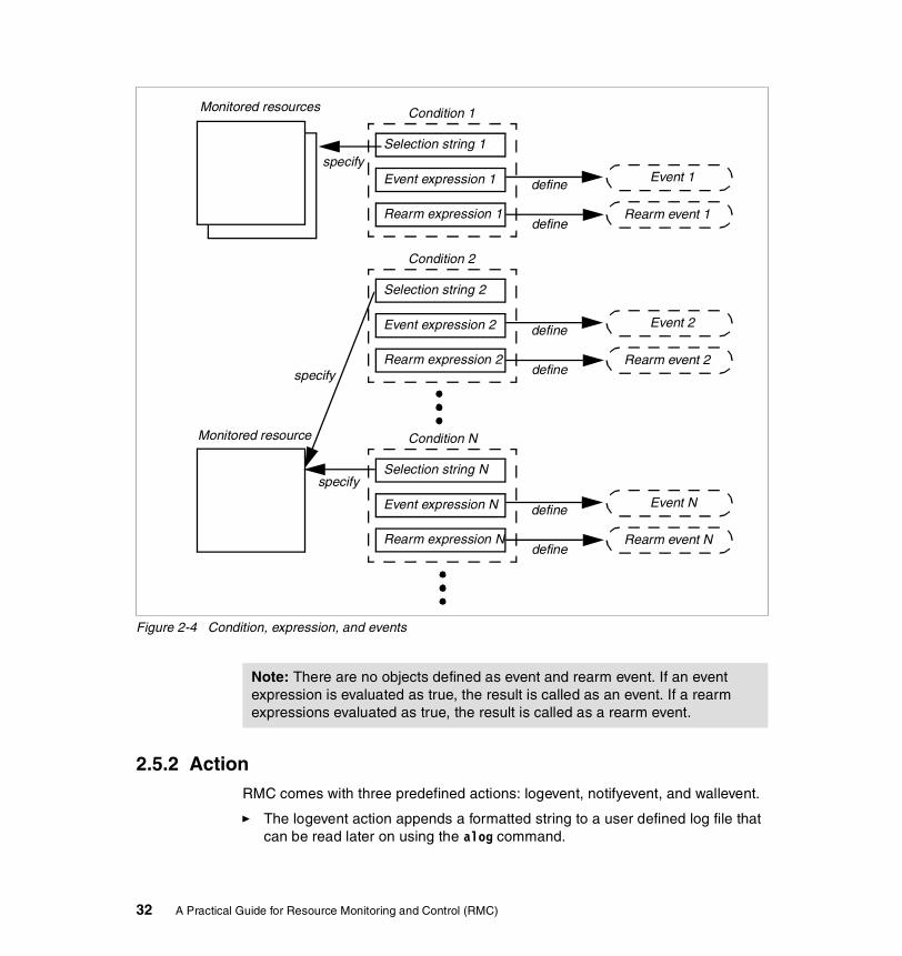
Figure 2-4 Condition, expression, and events
2.5.2 ActionRMC comes with three predefined actions: logevent, notifyevent, and wallevent.
� The logevent action appends a formatted string to a user defined log file that can be read later on using the alog command.
Monitored resources
Selection string 1
Condition 1
specify
Rearm event 1
define
define
Event expression 1
Rearm expression 1
Event 1
Selection string 2
Condition 2
Rearm event 2
define
define
Event expression 2
Rearm expression 2
Event 2
Selection string N
Condition N
Rearm event N
define
define
Event expression N
Rearm expression N
Event N
specify
Monitored resource
specify
Note: There are no objects defined as event and rearm event. If an event expression is evaluated as true, the result is called as an event. If a rearm expressions evaluated as true, the result is called as a rearm event.
32 A Practical Guide for Resource Monitoring and Control (RMC)
� The notifyevent action sends the content of the event to a user specified user ID using e-mail.
� The wallevent event broadcasts a message to all users using the wall command.
There are two variations of these actions, called elogevent, enotifyevent, and ewallevent, with the same functionality as the previous actions; however, these e-version actions always return messages in English, while the messages of the original three actions will depend upon the locale settings.
You can specify an action when it should be executed from the following cases:
� Only when the event defined by the associated condition occurs.
� Only when the rearm event defined by the associated condition occurs.
� Either the event or the rearm event defined by the associated condition occurs.
Finally, the user can also provide customized scripts as actions and the existing Korn shell scripts can be used as examples or starting points for more complex operations. The user defined scripts are executed in an environment where variables are set according to the event that would trigger the action. For example, the ERRM_RSRC_NAME variable would contain the name of the resource whose dynamic attribute change caused an event to fire.
For a complete list of the available environment variables, please refer to the IBM RSCT for AIX: Guide and Reference, SA22-7889.
2.5.3 ResponseA response is a set of zero12 or more actions that will be performed by the system when an expression of a condition evaluates to true. A response contains the following information on how the actions are executed:
� Arguments for the actions.
� Time ranges (periods) to describe when the action can be run.
� Definitions of environment variables to set before executing the action.
� The expected return code of the action and if the results of the action should be directed, for example, to the audit log.
Note: Do not confuse the actions used as part of a response with the actions that are part of a class or resource.
12 A response can contain no action if you just want to see the event log to AuditLog without running any actions.
Chapter 2. Architecture and components 33
In AIX 5L Version 5.1, RMC provides eight predefined responses (see Figure 3-12 on page 51). A response can be defined with multiple actions. For example, the critical notification response calls the following three predefined actions:
� Logging an entry in the /tmp/criticalEvents.log
� Sending e-mail to the root user
� Warning all logged use with wallevent
2.5.4 Association between a condition with a responseConditions and responses can exist without being used and with nothing related to each other. Actions are part of responses and only defined to responses. Although it is possible that multiple responses have an action using the same name, these actions do not refer to the same object. You can associate a response with multiple actions.
To start observing the monitored resource, a condition must be associated with at least one response. You can associate a condition with multiple responses. However, each pair of a condition and a response is considered a separate association. Once associated, the condition and response should be activated (started).
Figure 2-5 on page 35 illustrates the relationship between the conditions, the responses, and the actions. In this figure, there are three associations (A, B, and C).
Note: Throughout this redbook, we use a term, “condition and response”, to express an association between a condition and a response.
34 A Practical Guide for Resource Monitoring and Control (RMC)

Figure 2-5 Conditions, responses, and actions
2.6 Directory structure used by RMCRMC uses two major directories, /usr/sbin/rsct and /var/ct, to store files and data. Although there are many directories and files under them, the following list gives you a brief explanation about the directory structure used by RMC.
/var/ct Contains general information about the status and operation of RSCT (log files and so on). Also holds user specified security configuration files.
/var/ct/IW Files relevant to the IW (Independent Workstation) mode of operation (stand-alone, not clustered). If in a
Condition 1
Condition 2
Condition N
Action aResponse 1
Response 2
Response M
Action b
Action n
Association
A
B
CAction a
Note: The association has no name. The labels A, B, and C are for reference purposes. To refer to the specific association, you have to specify the condition name and the response name that make the association. For example, you have to specify the condition 1 and the response 1 to refer to the association A. Also, it must be clear that the same action name (in this example, action a) can be used in multiple responses, but these actions are different objects.
Note: Most RSCT commands are symbolic-linked in the /usr/bin directory. If you cannot find some RSCT commands, invoke them by adding /usr/sbin/rsct/bin to the command search path ($PATH).
Chapter 2. Architecture and components 35
cluster, relevant files will be in /var/ct/<cluster_id>, where cluster_id cannot be IW. The file IW is a symbolic link to a representation of the cluster ID, which is shown as a string of alphanumeric characters. All nodes in the same domain have the same cluster ID.
/var/ct/<cluster_id> Contains information (log files and so on) about the cluster cluster_id.
/usr/sbin/rsct Repository for configuration and utility files.
/usr/sbin/rsct/README Useful README files for RSCT that are recommended reading for users of RSCT RMC.
/usr/sbin/rsct/bin General RSCT binary files and predefined action scripts.
/usr/sbin/rsct/cfg Contains general configuration and default security configuration files.
/tmp/ctsupt Directory for diagnostic dump files for problem determination and analysis (log files, trace information, and so on). Data is generated by /usr/sbin/rsct/bin/ctsnap and is only collected from the invoking node.
For further information about directories and files used by RMC, please refer to the IBM RSCT for AIX: Technical Reference, SA22-7890.
Note: Many log files are stored under the /var/ct directory and their size can grow during normal system activity. To ensure trouble free operation, check that /var has available free space at all times. The predefined condition “/var space used” can be used to monitor the status and to provide a suitable automated response.
36 A Practical Guide for Resource Monitoring and Control (RMC)
Chapter 3. Quick start: using RMC
Resource Monitoring and Control (RMC) provides a highly flexible infrastructure to monitor and control AIX 5L Version 5.1 systems in either a stand-alone or a clustered environment.
This chapter explains how to use RMC in a stand-alone environment along with several examples using Web-based System Manager. It includes the following four sections:
� Section 3.1, “AIX 5L Version 5.1 Web-based System Manager” on page 38
� Section 3.2, “RMC setup procedure” on page 45
� Section 3.3, “Customizing your RMC configuration” on page 57
� Section 3.4, “Creating a new condition or response” on page 70
For the usage of RMC in a cluster environment, see Chapter 4, “RMC command line interface” on page 93.
3
Note: All the graphical images contained in this chapter are based on information that was available no later than June 2002. The detailed filesets level used in our test are shown in Appendix A, “Filesets level information” on page 175.
© Copyright IBM Corp. 2002. All rights reserved. 37
3.1 AIX 5L Version 5.1 Web-based System ManagerAIX 5L Version 5.1 Web-based System Manager provides an easy to use graphical user interface (GUI) with a familiar look and feel interface to users who have experienced working on a personal computer (PC), to be used for configuration and system management tasks. Web-based System Manager is installed, by default, upon AIX 5L Version 5.1 installation and is ready to use as soon as the system is available.
Web-based System Manager supports the following operation modes:
� Stand-alone application mode
� Client-Server mode
� PC applet mode
� PC client mode
To start Web-based System Manager in the stand-alone application mode13, which invokes the application on the local X Window system, just type wsm& on the command prompt. You will see the application window, as shown in Figure 3-1 on page 39.
13 The stand-alone application mode requires that a graphics display be equipped with the AIX system.
38 A Practical Guide for Resource Monitoring and Control (RMC)
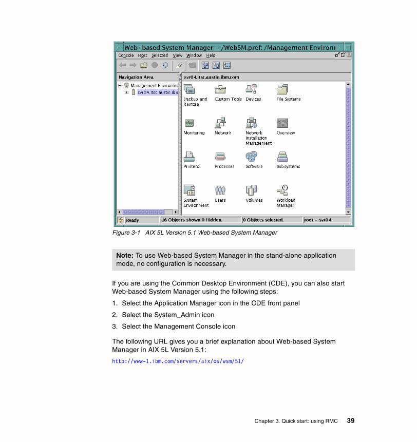
Figure 3-1 AIX 5L Version 5.1 Web-based System Manager
If you are using the Common Desktop Environment (CDE), you can also start Web-based System Manager using the following steps:
1. Select the Application Manager icon in the CDE front panel
2. Select the System_Admin icon
3. Select the Management Console icon
The following URL gives you a brief explanation about Web-based System Manager in AIX 5L Version 5.1:
http://www-1.ibm.com/servers/aix/os/wsm/51/
Note: To use Web-based System Manager in the stand-alone application mode, no configuration is necessary.
Chapter 3. Quick start: using RMC 39
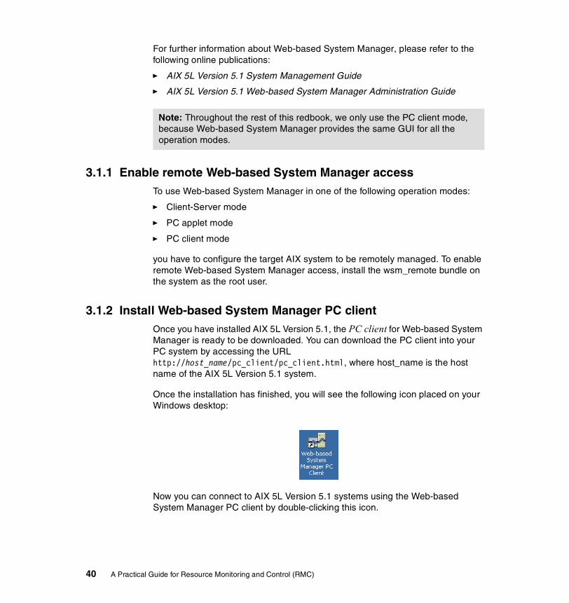
For further information about Web-based System Manager, please refer to the following online publications:
� AIX 5L Version 5.1 System Management Guide
� AIX 5L Version 5.1 Web-based System Manager Administration Guide
3.1.1 Enable remote Web-based System Manager accessTo use Web-based System Manager in one of the following operation modes:
� Client-Server mode
� PC applet mode
� PC client mode
you have to configure the target AIX system to be remotely managed. To enable remote Web-based System Manager access, install the wsm_remote bundle on the system as the root user.
3.1.2 Install Web-based System Manager PC clientOnce you have installed AIX 5L Version 5.1, the PC client for Web-based System Manager is ready to be downloaded. You can download the PC client into your PC system by accessing the URL http://host_name/pc_client/pc_client.html, where host_name is the host name of the AIX 5L Version 5.1 system.
Once the installation has finished, you will see the following icon placed on your Windows desktop:
Now you can connect to AIX 5L Version 5.1 systems using the Web-based System Manager PC client by double-clicking this icon.
Note: Throughout the rest of this redbook, we only use the PC client mode, because Web-based System Manager provides the same GUI for all the operation modes.
40 A Practical Guide for Resource Monitoring and Control (RMC)

3.1.3 Connect to AIX 5L Version 5.1 system using the PC clientTo connect to an AIX 5L Version 5.1 system using the Web-based System Manager PC client, do the following:
1. Double-click the “Web-based System Manager PC client” icon. You will see the Log On dialog box shown in Figure 3-2.
Figure 3-2 Log On dialog box
2. Enter the target AIX system’s host name in the dialog box.
3. Once the host name has been validated, enter the user name and password in the Log On dialog box, then click Log On.
If the user name and password you supplied in this panel is authenticated by the target AIX system, the connection is established successfully. After authentication, the granted access is classified into the following two privileges, depending on the supplied user name:
root Full read and write access to the system settings.
non-privileged Read access only to the system settings. User can do monitoring.
4. Then the Web-based System Manager window displays the target host name to be managed on the window title; the host name is also highlighted in the Navigation Area and the status bar, as shown in Figure 3-3 on page 42.
Chapter 3. Quick start: using RMC 41
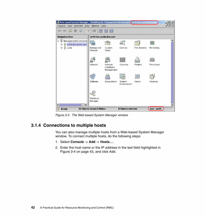
Figure 3-3 The Web-based System Manager window
3.1.4 Connections to multiple hostsYou can also manage multiple hosts from a Web-based System Manager window. To connect multiple hosts, do the following steps:
1. Select Console -> Add -> Hosts….
2. Enter the host name or the IP address in the text field highlighted in Figure 3-4 on page 43, and click Add.
42 A Practical Guide for Resource Monitoring and Control (RMC)

Figure 3-4 Adding hosts to the management environment
Once a host is added, it will appear under the Management Environment tree in the Navigation Area, as shown in Figure 3-5.
Figure 3-5 Selecting a host to manage
Chapter 3. Quick start: using RMC 43
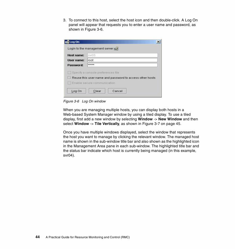
3. To connect to this host, select the host icon and then double-click. A Log On panel will appear that requests you to enter a user name and password, as shown in Figure 3-6.
Figure 3-6 Log On window
When you are managing multiple hosts, you can display both hosts in a Web-based System Manager window by using a tiled display. To use a tiled display, first add a new window by selecting Window -> New Window and then select Window -> Tile Vertically, as shown in Figure 3-7 on page 45.
Once you have multiple windows displayed, select the window that represents the host you want to manage by clicking the relevant window. The managed host name is shown in the sub-window title bar and also shown as the highlighted icon in the Management Area pane in each sub-window. The highlighted title bar and the status bar indicate which host is currently being managed (in this example, svr04).
44 A Practical Guide for Resource Monitoring and Control (RMC)

Figure 3-7 Tiled windows
3.2 RMC setup procedureThis section describes the general use and configuration of RMC from AIX 5L Version 5.1 Web-based System Manager for managing stand-alone servers.
3.2.1 Basic RMC conceptsBefore you start using Web-based System Manager to configure and manage RMC, you should be familiar with several RMC terms explained in this section. Figure 3-8 on page 46 shows the Condition property dialog box and the terms shown in this dialog box are also explained in this section.
Note: In AIX 5L Version 5.1, Web-based System Manager provides the functionality to configure stand-alone servers. If you are going to use RMC in a clustered environment, RMC should be configured and controlled using the command line interface.
Chapter 3. Quick start: using RMC 45
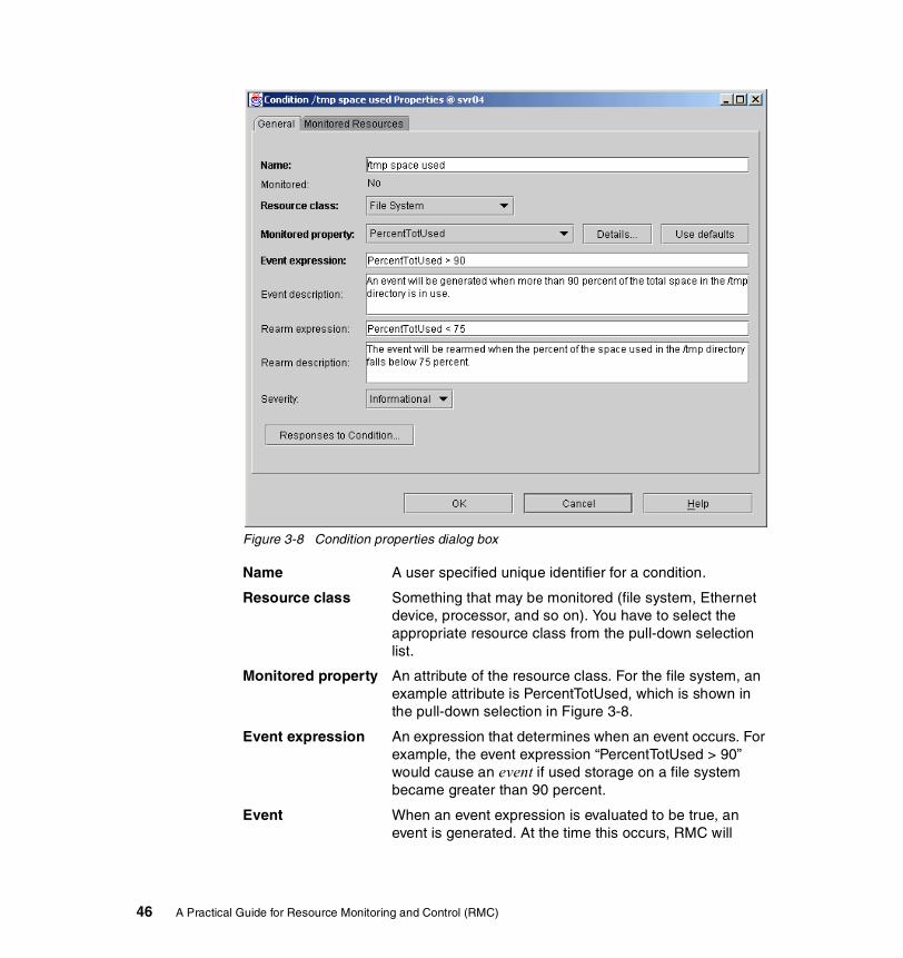
Figure 3-8 Condition properties dialog box
Name A user specified unique identifier for a condition.
Resource class Something that may be monitored (file system, Ethernet device, processor, and so on). You have to select the appropriate resource class from the pull-down selection list.
Monitored property An attribute of the resource class. For the file system, an example attribute is PercentTotUsed, which is shown in the pull-down selection in Figure 3-8.
Event expression An expression that determines when an event occurs. For example, the event expression “PercentTotUsed > 90” would cause an event if used storage on a file system became greater than 90 percent.
Event When an event expression is evaluated to be true, an event is generated. At the time this occurs, RMC will
46 A Practical Guide for Resource Monitoring and Control (RMC)

execute responses associated with the event and RMC will consider the event to be in a current (true) state.
Rearm expression An expression that determines when an rearm event occurs. For example the rearm expression “PercentTotUsed < 75” would cause a rearm event to occur if usage of a file system became less than 75 percent.
Rearm event When a rearm event expression is evaluated to be true, a rearm event is generated only when the corresponding event has occurred already. At the time this occurs, RMC will execute responses associated with the rearm event and RMC will consider the rearm event to be in a current (true) state.
Condition A named combination of properties including resource class, monitored property, event expression, and rearm expression. One of the predefined conditions is named “/tmp space used” and generates an event if /tmp is more than 90 percent used and a rearm event if /tmp is less than 75 percent used. The condition properties dialog box is shown in Figure 3-8 on page 46.
Response This is a user defined predetermined course of action that takes place when an event occurs. A response can be single or multiple actions. Figure 3-12 on page 51 shows the standard predefined responses on AIX 5L Version 5.1.
For further detailed explanation about terms used in RMC, see the following sections:
� Section 2.2, “Resource, resource class, and attribute” on page 19
� Section 2.4, “Expression” on page 30
� Section 2.5, “Condition, response, and action” on page 30
Note: The “monitored property” field in this dialog box refers to what is called an attribute (explained in Section 2.2.3, “Attribute” on page 21). It is different from the term property used in (Section 2.2.3, “Attribute” on page 21). However, we use the term “monitored property” to refer this field throughout this chapter to be consistent with the terminology used in Web-based System Manager.
Chapter 3. Quick start: using RMC 47

3.2.2 Step one: the Monitoring plug-inFor RMC, the first area of interest is the Monitoring plug-in. To open the plug-in, select Monitoring in the Navigation Area, as shown in Figure 3-9. To expand a sub-tree under the Monitoring icon, click the + symbol to the left of the icon. To collapse the sub-tree, click the - symbol.
Figure 3-9 Selecting the Monitoring plug-in
3.2.3 Step two: the Conditions plug-inIf you want to see what conditions have been defined, you first need to open the Conditions plug-in, which shows all the predefined conditions provided by AIX 5L Version 5.1, by double-clicking the Conditions icon in the Monitoring pane, as shown in Figure 3-10 on page 49. You can also open this plug-in by clicking the Conditions icon in the Navigation Area.
48 A Practical Guide for Resource Monitoring and Control (RMC)
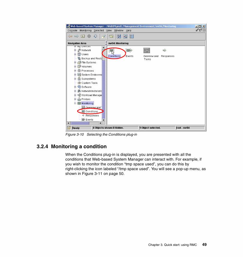
Figure 3-10 Selecting the Conditions plug-in
3.2.4 Monitoring a conditionWhen the Conditions plug-in is displayed, you are presented with all the conditions that Web-based System Manager can interact with. For example, if you wish to monitor the condition “tmp space used”, you can do this by right-clicking the icon labeled “/tmp space used”. You will see a pop-up menu, as shown in Figure 3-11 on page 50.
Chapter 3. Quick start: using RMC 49

Figure 3-11 Conditions pop-up window
To start monitoring the condition, select Start Monitoring... You will be presented with the Edit Responses to Start Monitoring dialog box, as shown in Figure 3-12 on page 51.
50 A Practical Guide for Resource Monitoring and Control (RMC)
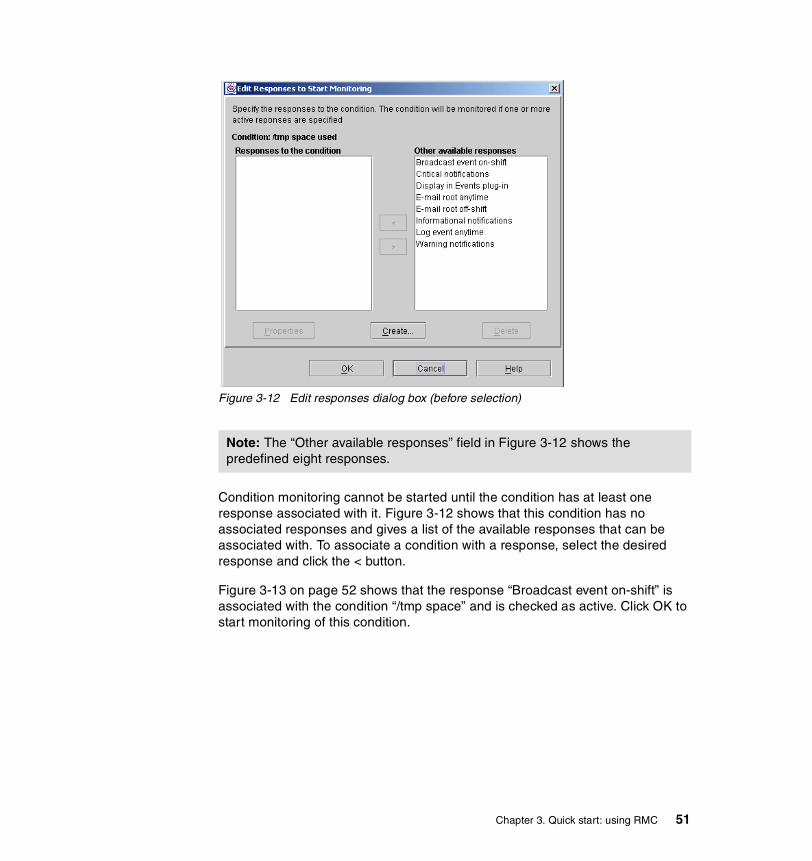
Figure 3-12 Edit responses dialog box (before selection)
Condition monitoring cannot be started until the condition has at least one response associated with it. Figure 3-12 shows that this condition has no associated responses and gives a list of the available responses that can be associated with. To associate a condition with a response, select the desired response and click the < button.
Figure 3-13 on page 52 shows that the response “Broadcast event on-shift” is associated with the condition “/tmp space” and is checked as active. Click OK to start monitoring of this condition.
Note: The “Other available responses” field in Figure 3-12 shows the predefined eight responses.
Chapter 3. Quick start: using RMC 51

Figure 3-13 Edit responses dialog box (after selection)
Once monitoring of a condition has been started, Web-based System Manager will show you the message window shown in Figure 3-14 on page 53.
52 A Practical Guide for Resource Monitoring and Control (RMC)

Figure 3-14 Monitoring started display
The system is now monitoring the condition “/tmp space used” and will perform the “Broadcast event on-shift” response when /tmp usage exceeds 90 percent and again when usage drops below 75 percent, this is described as an event and rearm event cycle.
To demonstrate the behavior, you can use the yes command to fill all the available space in /tmp, as shown in Example 3-1.
Example 3-1 Triggering /tmp space used, event and rearm
# df -k /tmpFilesystem 1024-blocks Free %Used Iused %Iused Mounted on/dev/hd3 32768 27356 17% 114 2% /tmp# yes > /tmp/yes.log
Broadcast message from [email protected] (tty) at 15:05:33 ...
Informational Event occurred for Condition /tmp on the resource /tmp of the resource class File System at Friday 06/07/02 15:05:32.The resource was monitored on svr04.itsc.austin.ibm.com and resided on {svr04.itsc.austin.ibm.com}.
Chapter 3. Quick start: using RMC 53

^C# rm /tmp/yes.log # df -k /tmp Filesystem 1024-blocks Free %Used Iused %Iused Mounted on/dev/hd3 32768 27356 17% 114 2% /tmp#
Broadcast message from [email protected] (tty) at 15:07:33 ...
Informational Rearm event occurred for Condition /tmp space used on theresource /tmp of the resource class File System at Friday 06/07/02 15:07:32.The resource was monitored on svr04.itsc.austin.ibm.com and resided on {svr04.itsc.austin.ibm.com}.
3.2.5 Viewing eventsThe response we associated with the “/tmp space used” condition in the previous example was to broadcast a message when the event and rearm event occurred, but this is not the only way of viewing event activity. For example, select the Monitoring view in Web-based System Manager, and then either right-click on the Events icon in the Navigation Area or double right-click on the Events icon in the Monitoring plug-in, as in Figure 3-15 on page 55.
Note: Because this example uses the “Broadcast event on-shift” response, the only times it will work will be between 8 a.m. and 5 p.m. on Monday to Friday.
54 A Practical Guide for Resource Monitoring and Control (RMC)

Figure 3-15 Selecting the Events plug-in
When the Events plug-in is selected, you have the option to view either all events that have occurred since this Web-based System Manager session was started or just the events that are current (an event has occurred, but no rearm event has yet occurred for that condition). Figure 3-16 on page 56 shows the Events plug-in (showing all events) displayed in conjunction with Example 3-1 on page 53.
Note: You can view the events through the Events plug-in only; you cannot start or stop monitoring using it.
Chapter 3. Quick start: using RMC 55
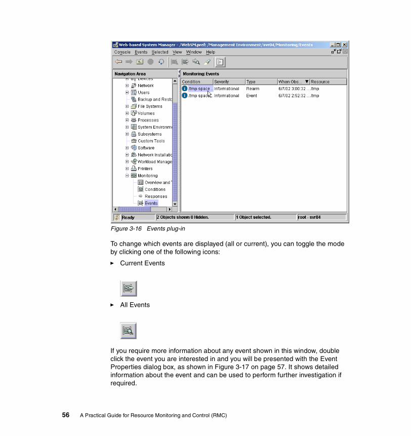
Figure 3-16 Events plug-in
To change which events are displayed (all or current), you can toggle the mode by clicking one of the following icons:
� Current Events
� All Events
If you require more information about any event shown in this window, double click the event you are interested in and you will be presented with the Event Properties dialog box, as shown in Figure 3-17 on page 57. It shows detailed information about the event and can be used to perform further investigation if required.
56 A Practical Guide for Resource Monitoring and Control (RMC)
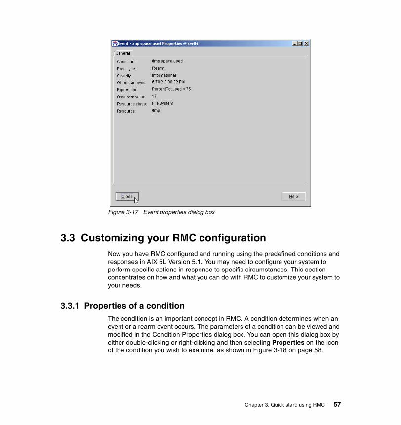
Figure 3-17 Event properties dialog box
3.3 Customizing your RMC configurationNow you have RMC configured and running using the predefined conditions and responses in AIX 5L Version 5.1. You may need to configure your system to perform specific actions in response to specific circumstances. This section concentrates on how and what you can do with RMC to customize your system to your needs.
3.3.1 Properties of a conditionThe condition is an important concept in RMC. A condition determines when an event or a rearm event occurs. The parameters of a condition can be viewed and modified in the Condition Properties dialog box. You can open this dialog box by either double-clicking or right-clicking and then selecting Properties on the icon of the condition you wish to examine, as shown in Figure 3-18 on page 58.
Chapter 3. Quick start: using RMC 57

Figure 3-18 Displaying the properties of a condition
Condition propertiesThe Condition Properties dialog box shows the current properties associated with a condition. An example of the Condition Properties dialog box is shown in Figure 3-19 on page 59 and Figure 3-20 on page 60.
AIX 5L Version 5.1 provides a predefined set of conditions that may be used for monitoring system resources, and, if required, new conditions can be added or existing conditions may have their properties changed; these properties may be changed at any time.
3.3.2 Monitored resourcesConditions are configured to monitor resources on your AIX system and these resources are categorized into resource classes. In a resource class, there are multiple resources that can be monitored. For example, all the file systems in the system are represented as a resource in the file system resource class. This section shows how this characteristic may be used. To examine or change
58 A Practical Guide for Resource Monitoring and Control (RMC)

properties of a condition, display the Conditions Properties dialog box, as explained in Section 3.3.1, “Properties of a condition” on page 57.
Figure 3-19 shows the Condition Properties dialog box for the “/tmp space used” condition. In this example, we are monitoring a resource in the file system resource class, as shown in the Resource class: field.
Figure 3-19 Condition Properties dialog box
Because there is more than one file system on the system besides /tmp, you have to specify that you are only interested in /tmp for this condition. This is shown in the Monitored Resources tab in the dialog box. To view or modify the monitored resources, click the Monitored Resources tab.
Figure 3-20 on page 60 shows the monitored resources page for this condition. The dialog box indicates that the predefined condition “/tmp used space” is monitoring /tmp only.
Chapter 3. Quick start: using RMC 59
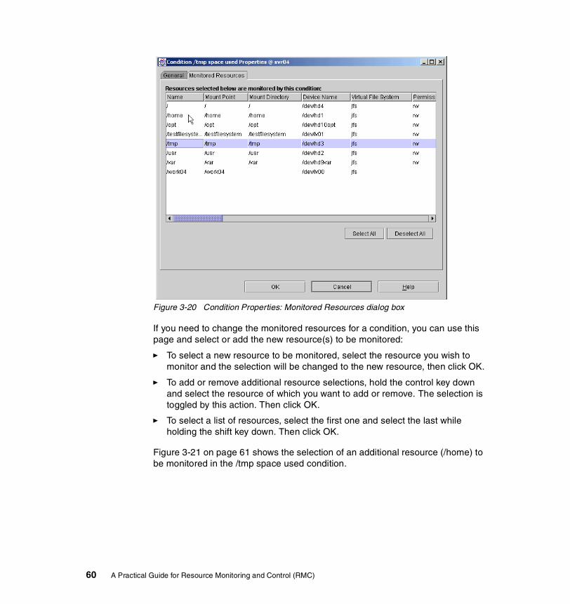
Figure 3-20 Condition Properties: Monitored Resources dialog box
If you need to change the monitored resources for a condition, you can use this page and select or add the new resource(s) to be monitored:
� To select a new resource to be monitored, select the resource you wish to monitor and the selection will be changed to the new resource, then click OK.
� To add or remove additional resource selections, hold the control key down and select the resource of which you want to add or remove. The selection is toggled by this action. Then click OK.
� To select a list of resources, select the first one and select the last while holding the shift key down. Then click OK.
Figure 3-21 on page 61 shows the selection of an additional resource (/home) to be monitored in the /tmp space used condition.
60 A Practical Guide for Resource Monitoring and Control (RMC)
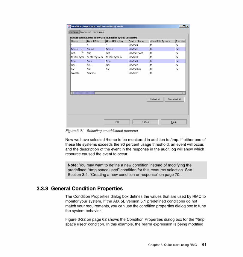
Figure 3-21 Selecting an additional resource
Now we have selected /home to be monitored in addition to /tmp. If either one of these file systems exceeds the 90 percent usage threshold, an event will occur, and the description of the event in the response in the audit log will show which resource caused the event to occur.
3.3.3 General Condition PropertiesThe Condition Properties dialog box defines the values that are used by RMC to monitor your system. If the AIX 5L Version 5.1 predefined conditions do not match your requirements, you can use the condition properties dialog box to tune the system behavior.
Figure 3-22 on page 62 shows the Condition Properties dialog box for the “/tmp space used” condition. In this example, the rearm expression is being modified
Note: You may want to define a new condition instead of modifying the predefined “/tmp space used” condition for this resource selection. See Section 3.4, “Creating a new condition or response” on page 70.
Chapter 3. Quick start: using RMC 61
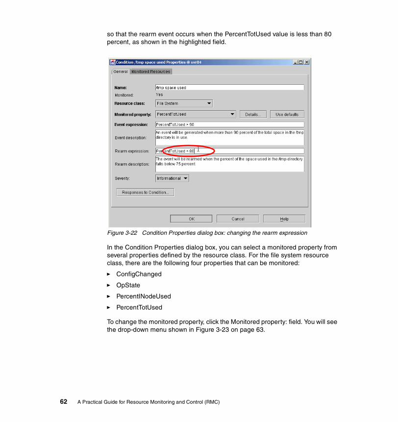
so that the rearm event occurs when the PercentTotUsed value is less than 80 percent, as shown in the highlighted field.
Figure 3-22 Condition Properties dialog box: changing the rearm expression
In the Condition Properties dialog box, you can select a monitored property from several properties defined by the resource class. For the file system resource class, there are the following four properties that can be monitored:
� ConfigChanged
� OpState
� PercentINodeUsed
� PercentTotUsed
To change the monitored property, click the Monitored property: field. You will see the drop-down menu shown in Figure 3-23 on page 63.
62 A Practical Guide for Resource Monitoring and Control (RMC)

Figure 3-23 Condition Properties dialog box: changing the monitored property
3.3.4 Responses to a conditionBefore configuring RMC, it is important to understand the relationship between conditions and responses. A condition includes the following information:
� Resource(s) to be monitored
� An event expression
� A rearm event expression (optional)
Then the condition can be associated with one or more responses. AIX 5L Version 5.1 provides a set of predefined responses and these can be associated with any conditions, including the predefined conditions.
You can change the association between a condition and responses by clicking the Responses to Condition… button in the Condition Properties panel, as shown in Figure 3-24 on page 64.
Chapter 3. Quick start: using RMC 63
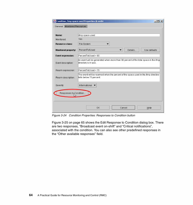
Figure 3-24 Condition Properties: Responses to Condition button
Figure 3-25 on page 65 shows the Edit Response to Condition dialog box. There are two responses, “Broadcast event on-shift” and “Critical notifications”, associated with the condition. You can also see other predefined responses in the “Other available responses” field.
64 A Practical Guide for Resource Monitoring and Control (RMC)

Figure 3-25 Edit Responses to Condition
To see the detailed information about a response, select the response in the panel, then click the Properties button.
Figure 3-26 on page 66 shows the properties dialog box of the “Critical notifications” response. In this example, the “Critical notifications” response comprises the following three actions:
� Log critical event� E-mail root� Broadcast message
The properties of the response are displayed in the Response Properties dialog box and this shows what actions are taken by the response. A response can have one or more actions and each action can perform a different task.
Chapter 3. Quick start: using RMC 65
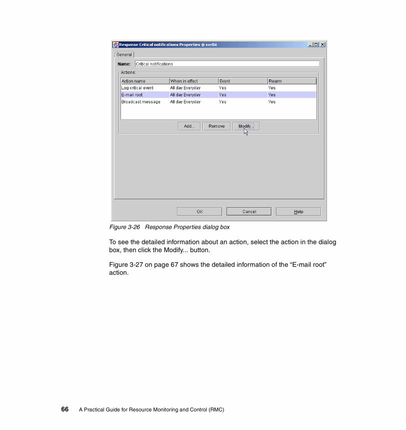
Figure 3-26 Response Properties dialog box
To see the detailed information about an action, select the action in the dialog box, then click the Modify... button.
Figure 3-27 on page 67 shows the detailed information of the “E-mail root” action.
66 A Practical Guide for Resource Monitoring and Control (RMC)
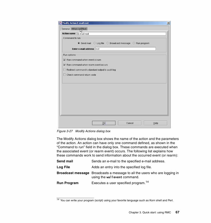
Figure 3-27 Modify Actions dialog box
The Modify Actions dialog box shows the name of the action and the parameters of the action. An action can have only one command defined, as shown in the “Command to run” field in the dialog box. These commands are executed when the associated event (or rearm event) occurs. The following list explains how these commands work to send information about the occurred event (or rearm):
Send mail Sends an e-mail to the specified e-mail address.
Log File Adds an entry into the specified log file.
Broadcast message Broadcasts a message to all the users who are logging in using the wallevent command.
Run Program Executes a user specified program.14
14 You can write your program (script) using your favorite language such as Korn shell and Perl.
Chapter 3. Quick start: using RMC 67

If you select Run Program, then the specified program is invoked with a set of environment variables set by RMC.
Actions can be specified to run at certain times of the day or days of the week. Thus, RMC can be configured to perform different actions for events occurring during normal work hours or occurring overnight. Click the “When in Effect” tab to display the time settings of the action, as shown in Figure 3-28.
Figure 3-28 Modify Action: When in Effect
If you click the Add button, then the Time of Day and the Day of Week radio buttons will become selectable, as shown in Figure 3-29 on page 69.
68 A Practical Guide for Resource Monitoring and Control (RMC)

Figure 3-29 Modify action: setting the new period
To add a new period, select the time of day and day (or days) of the week. When you have completed your selection, click the Set button and your new selection will appear, as shown in Figure 3-30 on page 70.
Chapter 3. Quick start: using RMC 69
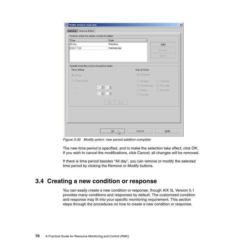
Figure 3-30 Modify action: new period addition complete
The new time period is specified, and to make the selection take effect, click OK. If you wish to cancel the modifications, click Cancel; all changes will be removed.
If there is time period besides “All day”, you can remove or modify the selected time period by clicking the Remove or Modify buttons.
3.4 Creating a new condition or responseYou can easily create a new condition or response, though AIX 5L Version 5.1 provides many conditions and responses by default. The customized condition and response may fit into your specific monitoring requirement. This section steps through the procedures on how to create a new condition or response.
70 A Practical Guide for Resource Monitoring and Control (RMC)

3.4.1 Creating a new conditionWeb-based System Manager provides you with several ways to create a new condition. For example, you can select the “Create a new condition” task in the the Overview and Tasks plug-in, as shown in Figure 3-31.
Figure 3-31 Creating a new condition from the Overview and Tasks plug-in
You can also create a new condition by clicking the following icon:
Both methods will pop up the New Condition dialog box as shown in Figure 3-32 on page 72. The dialog box allows you to define the properties of the new condition. For example, you can define a condition that monitors the state of a file system and associate it with a response that mounts the file system automatically if RMC detects that the file system is unmounted.
Chapter 3. Quick start: using RMC 71

Figure 3-32 New Condition dialog box
To create a new condition, do the following in the dialog box:
1. Select the appropriate resource class from the pull-down menu in the “Resource class” field. In Figure 3-32, we selected the File System resource class.
2. Specify a condition name in the Name: field. This condition name must be unique in the system and self-descriptive to explain the purpose of the condition. In Figure 3-32, we specified “Check /work04” as the condition name.
72 A Practical Guide for Resource Monitoring and Control (RMC)
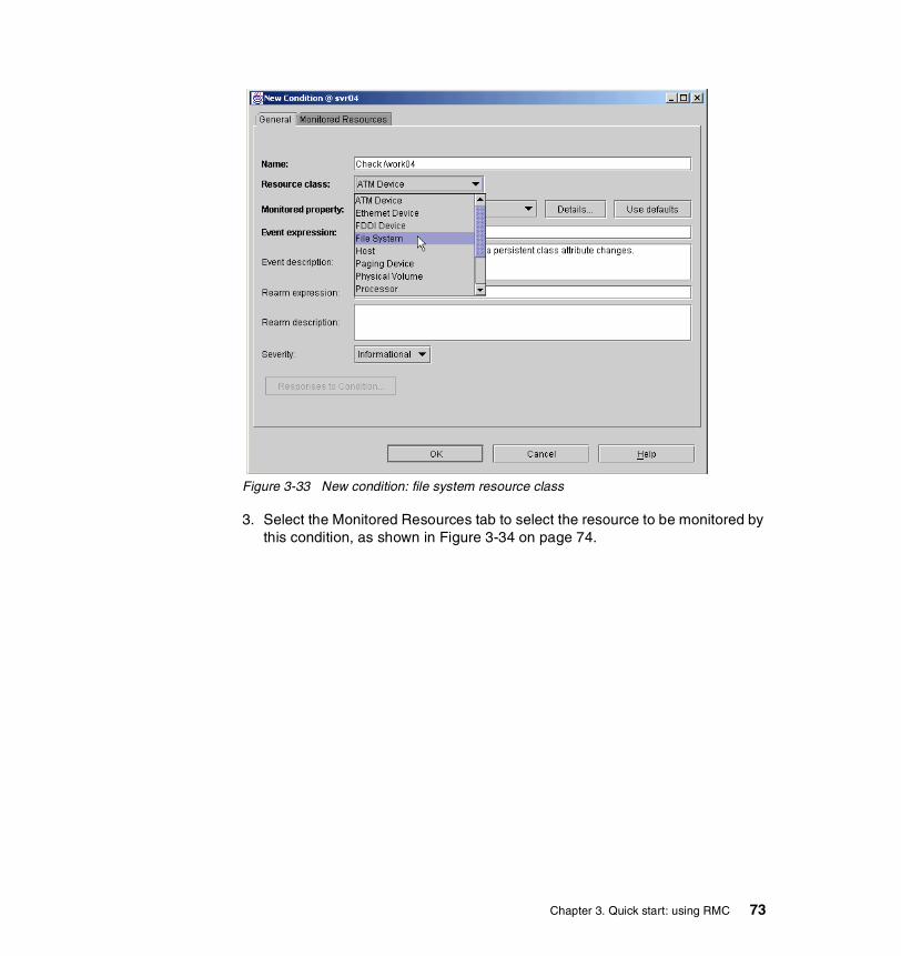
Figure 3-33 New condition: file system resource class
3. Select the Monitored Resources tab to select the resource to be monitored by this condition, as shown in Figure 3-34 on page 74.
Chapter 3. Quick start: using RMC 73

Figure 3-34 New condition: monitored resources, all file systems
In this example, we only selected the /work04 file system, as shown in Figure 3-35 on page 75.
74 A Practical Guide for Resource Monitoring and Control (RMC)
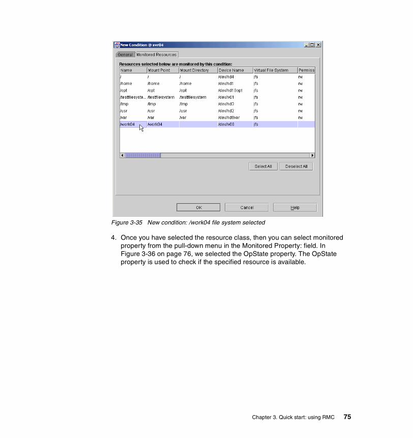
Figure 3-35 New condition: /work04 file system selected
4. Once you have selected the resource class, then you can select monitored property from the pull-down menu in the Monitored Property: field. In Figure 3-36 on page 76, we selected the OpState property. The OpState property is used to check if the specified resource is available.
Chapter 3. Quick start: using RMC 75
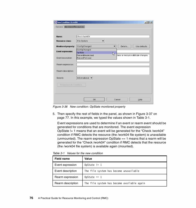
Figure 3-36 New condition: OpState monitored property
5. Then specify the rest of fields in the panel, as shown in Figure 3-37 on page 77. In this example, we typed the values shown in Table 3-1.
Event expressions are used to determine if an event or rearm event should be generated for conditions that are monitored. The event expression OpState != 1 means that an event will be generated for the “Check /work04” condition if RMC detects the resource (the /work04 file system) is unavailable (unmounted). The rearm expression OpState == 1 means that a rearm will be generated for the “Check /work04” condition if RMC detects that the resource (the /work04 file system) is available again (mounted).
Table 3-1 Values for the new condition
Field name Value
Event expression OpState != 1
Event description The file system has become unavailable
Rearm expression OpState == 1
Rearm description The file system has become available again
76 A Practical Guide for Resource Monitoring and Control (RMC)

Figure 3-37 New condition, expressions completed
6. Select the severity level by selecting the pull-down menu in the Severity: field, as shown in Figure 3-38 on page 78. The severity level indicates the relative importance compared to other conditions. Then click OK.
Chapter 3. Quick start: using RMC 77
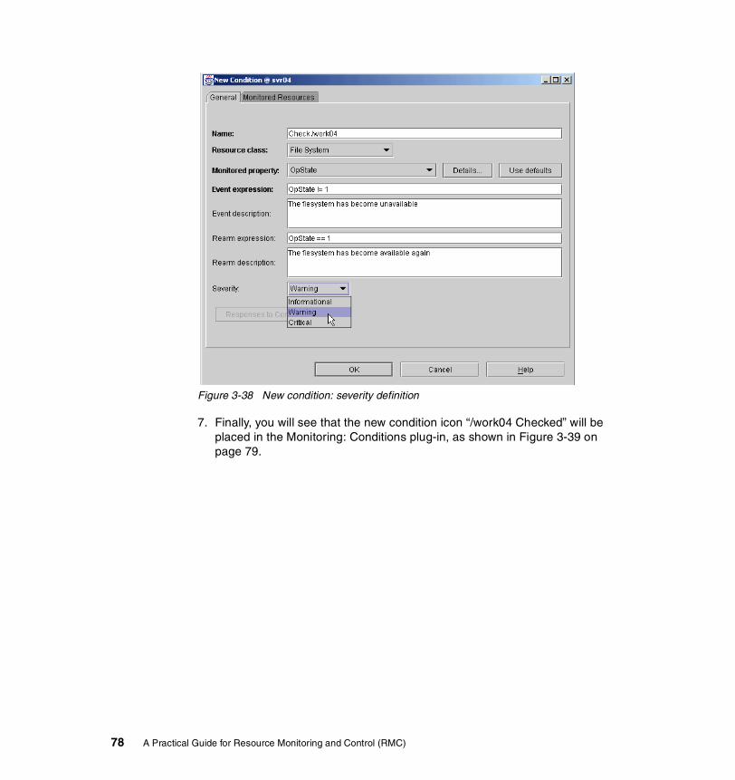
Figure 3-38 New condition: severity definition
7. Finally, you will see that the new condition icon “/work04 Checked” will be placed in the Monitoring: Conditions plug-in, as shown in Figure 3-39 on page 79.
78 A Practical Guide for Resource Monitoring and Control (RMC)

Figure 3-39 New condition created
If you select the events plug-in by selecting the following Events tree, the Events plug-in shows events that have occurred on the monitored system and indicate the severity of the event, as designated in the condition properties dialog box:
Figure 3-40 on page 80 displays with All Events selected to show all the events that have occurred during this session. To change the display mode, select the appropriate icon (current and all), as explained in Section 3.2.5, “Viewing events” on page 54.
Chapter 3. Quick start: using RMC 79
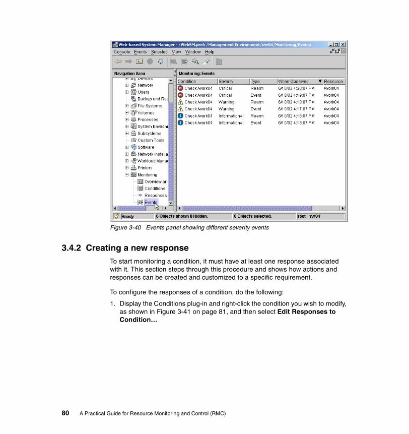
Figure 3-40 Events panel showing different severity events
3.4.2 Creating a new responseTo start monitoring a condition, it must have at least one response associated with it. This section steps through this procedure and shows how actions and responses can be created and customized to a specific requirement.
To configure the responses of a condition, do the following:
1. Display the Conditions plug-in and right-click the condition you wish to modify, as shown in Figure 3-41 on page 81, and then select Edit Responses to Condition…
80 A Practical Guide for Resource Monitoring and Control (RMC)

Figure 3-41 New response: drop-down menu
2. You will see the Edit Response to Condition dialog box, as shown in Figure 3-42 on page 82.
In this dialog box, you can do the following tasks:
– Associate the available responses, including predefined ones, with the condition.
– Create your own response and associate it with the condition.
– Modify the association between the condition and the responses.
– Delete the responses that you do not need any more.
Chapter 3. Quick start: using RMC 81
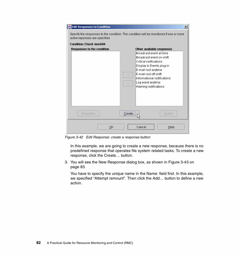
Figure 3-42 Edit Response: create a response button
In this example, we are going to create a new response, because there is no predefined response that operates file system related tasks. To create a new response, click the Create… button.
3. You will see the New Response dialog box, as shown in Figure 3-43 on page 83.
You have to specify the unique name in the Name: field first. In this example, we specified “Attempt remount”. Then click the Add… button to define a new action.
82 A Practical Guide for Resource Monitoring and Control (RMC)

Figure 3-43 New Response dialog box: specifying the name of the response
4. You will see the Add Action panel.
In this example, we provided an action name and selected “Run program” in the command to run field in Figure 3-44 on page 84. The string specified in the “Enter program name” field, /home/remount, is the shell script path name to be executed as an action if the response is triggered.
For further information how to use this dialog box, see Figure 3-27 on page 67. See Example 3-2 on page 90 for an example of the /home/remount script.
Chapter 3. Quick start: using RMC 83

Figure 3-44 Add Action dialog box
5. You have to specify when the action is actually in effect by clicking the When in Effect tab in the Add Action dialog box, as shown in Figure 3-45 on page 85.
84 A Practical Guide for Resource Monitoring and Control (RMC)
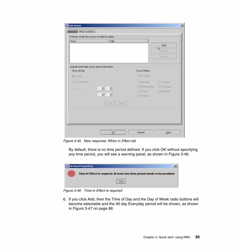
Figure 3-45 New response: When in Effect tab
By default, there is no time period defined. If you click OK without specifying any time period, you will see a warning panel, as shown in Figure 3-46.
Figure 3-46 Time in Effect is required
6. If you click Add, then the Time of Day and the Day of Week radio buttons will become selectable and the All day Everyday period will be shown, as shown in Figure 3-47 on page 86.
Chapter 3. Quick start: using RMC 85
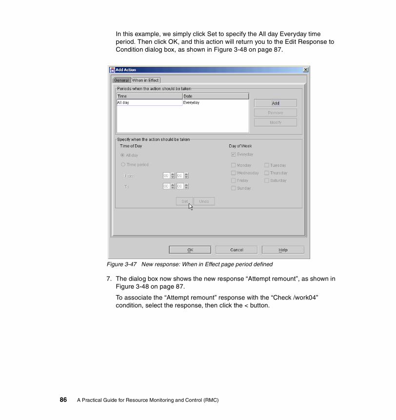
In this example, we simply click Set to specify the All day Everyday time period. Then click OK, and this action will return you to the Edit Response to Condition dialog box, as shown in Figure 3-48 on page 87.
Figure 3-47 New response: When in Effect page period defined
7. The dialog box now shows the new response “Attempt remount”, as shown in Figure 3-48 on page 87.
To associate the “Attempt remount” response with the “Check /work04” condition, select the response, then click the < button.
86 A Practical Guide for Resource Monitoring and Control (RMC)

Figure 3-48 New Response: Attempt remount created
8. Then the “Attempt remount” response will appear in the “Responses to the condition” field, as shown in Figure 3-49 on page 88.
Click OK to make this association take effect.
Chapter 3. Quick start: using RMC 87

Figure 3-49 New Response: Attempt remount selected as a response
Once you have associated one or more responses with a condition, monitoring is started and a message is displayed as shown in Figure 3-50 on page 89.
At this point, the “Check /work04” condition is being monitored and the associated response will be performed if the operational state of /work04 changes.
88 A Practical Guide for Resource Monitoring and Control (RMC)

Figure 3-50 New condition starts monitoring
3.4.3 The /home/remount scriptThe /home/remount script shown in Example 3-2 on page 90 will perform the following several activities if an event or rearm event for the monitoring condition “Check /work04” is detected by RMC:
1. Prints several environment values provided by RMC. When the script runs, the output is sent to the /tmp/inform file.
2. Checks if the event is a rearm event. If this is a rearm, the script just exits.
3. If this is an event, the script attempts to mount /work04 and, if successful, this will cause a rearm event.
4. Checks the return code of the mount. If the command fails, then a diagnostics message is printed. It would be a good idea to issue snap -gbc in the script to gather information for problem diagnosis.
5. If the command is succeeds, the relevant messages are printed.
Chapter 3. Quick start: using RMC 89
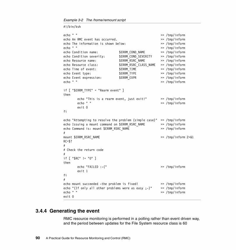
Example 3-2 The /home/remount script
#!/bin/ksh
echo " " >> /tmp/informecho An RMC event has occurred. >> /tmp/informecho The information is shown below: >> /tmp/informecho " " >> /tmp/informecho Condition name: $ERRM_COND_NAME >> /tmp/informecho Condition severity: $ERRM_COND_SEVERITY >> /tmp/informecho Resource name: $ERRM_RSRC_NAME >> /tmp/informecho Resource class: $ERRM_RSRC_CLASS_NAME >> /tmp/informecho Time of event: $ERRM_TIME >> /tmp/informecho Event type: $ERRM_TYPE >> /tmp/informecho Event expression: $ERRM_EXPR >> /tmp/informecho " " >> /tmp/inform
if [ "$ERRM_TYPE" = "Rearm event" ]then echo "This is a rearm event, just exit!" >> /tmp/inform echo " " >> /tmp/inform exit 0fi
echo "Attempting to resolve the problem (simple case)" >> /tmp/informecho Issuing a mount command on $ERRM_RSRC_NAME >> /tmp/informecho Command is: mount $ERRM_RSRC_NAME >> /tmp/inform#mount $ERRM_RSRC_NAME >> /tmp/inform 2>&1RC=$?## Check the return code#if [ "$RC" != "0" ]then echo "FAILED :-(" >> /tmp/inform exit 1fi#echo mount succeeded -the problem is fixed! >> /tmp/informecho "(If only all other problems were as easy ;-)" >> /tmp/informecho " " >> /tmp/informexit 0
3.4.4 Generating the eventRMC resource monitoring is performed in a polling rather than event driven way, and the period between updates for the File System resource class is 60
90 A Practical Guide for Resource Monitoring and Control (RMC)

seconds. Therefore, once /work04 is unmounted, there will be a period of up to 60 seconds before RMC is aware of the change of state (event) and, following the response, it will take up to 60 seconds again before RMC is aware that the resource is available (rearm event).
When the condition “Check /work04” is being monitored, you can easily trigger the response “Attempt remount” by issuing umount /work04.
Once the event has occurred, the /home/remount script logs messages generated by both the event and the rearm event in the /tmp/inform file, as shown in the following example:
An RMC event has occurred.The information is shown below:
Condition name: Check /work04Condition severity: WarningResource name: /work04Resource class: File SystemTime of event: 1023645967,14549Event type: EventEvent expression: OpState != 1
Attempting to resolve the problem (simple case)Issuing a mount command on /work04Command is: mount /work04mount succeeded -the problem is fixed!(If only all other problems were as easy ;-)
An RMC event has occurred.The information is shown below:
Condition name: Check /work04Condition severity: WarningResource name: /work04Resource class: File SystemTime of event: 1023646027,22140Event type: Rearm eventEvent expression: OpState == 1
This is a rearm event, just exit!
You can also view the events using the Web-based System Manager by selecting the Monitoring: Events plug-in and the View All Events icon, as shown in Figure 3-51 on page 92.
Chapter 3. Quick start: using RMC 91

Figure 3-51 Monitoring: Events window (all events)
92 A Practical Guide for Resource Monitoring and Control (RMC)

Chapter 4. RMC command line interface
This chapter focuses on the use of the RMC command line interface, presenting several examples of their use in our test environment, which is configured as shown in Section 4.1, “Test environment” on page 94.
The following two sections provide you with general concepts of the RMC command line interface usage:
� Section 4.2, “Common variables and command flags” on page 95
� Section 4.3, “A peer domain cluster setup” on page 106
The rest of sections in this chapter present a significant subset of the RSCT Resource Monitoring and Control commands, grouped by component: SRC, RMC, ERRM, and other resource monitors.
The last section, Section 4.10, “Additional security configuration” on page 143, explains the concept of security function that is provided by RMC and how to configure it on the stand-alone servers.
For further information about RMC commands and their usage, please refer to the IBM RSCT for AIX: Technical Reference, SA22-7890.
4
© Copyright IBM Corp. 2002. All rights reserved. 93

4.1 Test environmentThe test environment consists of four RS/6000 servers, as shown in Figure 4-1. The server svr01 is configured as a stand-alone RMC node, while svr02, svr04, and svr05 are configured as members of a peer domain. The host name resolution15 is done by DNS and all the servers are defined in the itsc.austin.ibm.com DNS domain. We refer to the servers either by their short names or fully qualified domain names (FQDNs) in this chapter.
Figure 4-1 RMC test environment
A NFS exported file system, /SharedTools, is defined on svr02 to hold common files, and svr04 and svr05 mount this file system remotely. Although the setup of a cluster does not require the existence of a shared data storage, we have decided to share files among the cluster nodes for ease of use. Any script that will be defined for the customization of RMC and that is likely to be used on any cluster node will be placed in this shared file system.
For systems where security is strongly concerned, we recommend you use rsync or SUP (Software Update Protocol) to synchronize files among servers. For further information about these tools, please refer to Managing AIX Server Farms, SG24-6606.
Please note all the examples in this chapter are executed as the root user, except for Section 4.10, “Additional security configuration” on page 143.
15 The hostname command returns FQDN on these servers.
svr0143P-150
svr05F80
svr04F80
svr0243P-150
Ethernet
Token Ring
Shared file system
NFS mount
Peer Domain
Standalone RMC node
94 A Practical Guide for Resource Monitoring and Control (RMC)
4.2 Common variables and command flagsRSCT Resource Monitoring and Control consists of many components: the RMC subsystem (the ctrmc daemon), resource managers, and so on. Each component has its own interface, which follows general rules common to all RMC components, as explained in IBM RSCT for AIX: Technical Reference, SA22-7890.
In this section, we explain the most commonly applied rules of these variables and command flags.
4.2.1 Environment variablesRMC is a distributed environment, where commands can be executed on any node in a cluster to act on any node in the cluster. Two environment variables, CT_CONTACT and CT_MANAGEMENT_SCOPE, control the behavior of all RMC commands with regard to the geographical aspects of RMC. However, some CLI commands, such as configuration manager CLI, ignore CT_MANAGEMENT_SCOPE. Therefore, you must consult with the command reference for each command before using that command.
In a stand-alone environment, these variables should be left undefined so that the CLI commands select the default behavior.
In a cluster environment, the end user may be using the CLI on a node that is not where he wants the command to be executed (for acting on resources on one or many other nodes).
CT_CONTACTThis variable defines where the command will be executed. It should contain the host name or the IP address of the host where the command will be executed. If you are not logged on the target node, the CLI contacts the RMC daemon on the target host specified by CT_CONTACT and passes it the commands to be
Note: Throughout this chapter, besides Section 4.10, “Additional security configuration” on page 143, we present examples for the general case of a peer domain environment. We therefore often refer to servers as nodes. However, RMC can also be used in a stand-alone environment, and any further statement related to a node also applies to a stand-alone server.
Note: CT_CONTACT and CT_MANAGEMENT_SCOPE are only applicable to the CLI. They do not affect the Web-based System Manager GUI.
Chapter 4. RMC command line interface 95

executed. If the variable is unset, the default is to execute the command on the local node.
In Example 4-1, you are logged onto server svr04 and have issued the lsrsrc command to display the Name attribute of the IBM.Host resource locally known by the RMC subsystem on svr04. After changing the CT_CONTACT variable to svr02, the same command is executed on svr02 while you are still logged on svr04.
Example 4-1 Impact of CT_CONTACT on command results
# hostnamesvr04.itsc.austin.ibm.com# echo $CT_CONTACT... nothing printed ...# lsrsrc IBM.Host NameResource Persistent Attributes for: IBM.Hostresource 1: Name = "svr04.itsc.austin.ibm.com"# export CT_CONTACT=svr02# lsrsrc IBM.Host NameResource Persistent Attributes for: IBM.Hostresource 1: Name = "svr02.itsc.austin.ibm.com"
Figure 4-2 on page 97 illustrates the concept of CT_CONTACT. The arrow A represents the command with CT_CONTACT unset, while the arrow B represents the command with CT_CONTACT set to svr02.
96 A Practical Guide for Resource Monitoring and Control (RMC)

Figure 4-2 The concept of CT_CONTACT
CT_MANAGEMENT_SCOPEThis variable specifies whether commands apply to only local resources or to resources located on the other nodes in the cluster. This variable can be set to an integer value of 0, 1, 2, or 3.
Table 4-1 CT_MANAGEMENT_SCOPE
If the CT_MANAGEMENT_SCOPE variable is not set to any value, the default value is 0, therefore commands refer to resources on the local node only.
In Example 4-2, you execute the lsrsrc command on svr02, as implied by the CT_CONTACT variable settings. By simply changing the CT_MANAGEMENT_SCOPE variable to 0 or 2, you can list, with the same command, the name of all hosts known respectively to the default scope or the entire peer domain.
Example 4-2 Impact of CT_MANAGEMENT_SCOPE variable
# echo $CT_CONTACTsvr02
RMC client(CLI)
RMC subsystem
svr02
RSCT RSCT
AB
RMC client(CLI)
RMC subsystem
svr04
RMC client(CLI)
RMC subsystem
svr05
: Resources and Resource classes
Value Where commands refer to
0 or 1 Resources on local node only
2 Resources on all the nodes in a peer domain
3 Resources on all the nodes in a management domain
Chapter 4. RMC command line interface 97
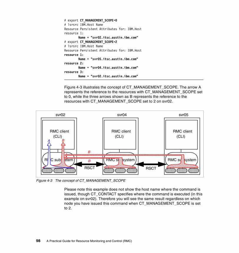
# export CT_MANAGEMENT_SCOPE=0# lsrsrc IBM.Host NameResource Persistent Attributes for: IBM.Hostresource 1: Name = "svr02.itsc.austin.ibm.com"# export CT_MANAGEMENT_SCOPE=2# lsrsrc IBM.Host NameResource Persistent Attributes for: IBM.Hostresource 1: Name = "svr05.itsc.austin.ibm.com"resource 2: Name = "svr04.itsc.austin.ibm.com"resource 3: Name = "svr02.itsc.austin.ibm.com"
Figure 4-3 illustrates the concept of CT_MANAGEMENT_SCOPE. The arrow A represents the reference to the resources with CT_MANAGEMENT_SCOPE set to 0, while the three arrows shown as B represents the reference to the resources with CT_MANAGEMENT_SCOPE set to 2 on svr02.
Figure 4-3 The concept of CT_MANAGEMENT_SCOPE
Please note this example does not show the host name where the command is issued, though CT_CONTACT specifies where the command is executed (in this example on svr02). Therefore you will see the same result regardless on which node you have issued this command when CT_MANAGEMENT_SCOPE is set to 2.
RMC client(CLI)
RMC subsystem
svr02
RSCT
A B
RMC client(CLI)
RMC subsystem
svr04
RMC client(CLI)
RMC subsystem
svr05
B
RSCT
B
98 A Practical Guide for Resource Monitoring and Control (RMC)
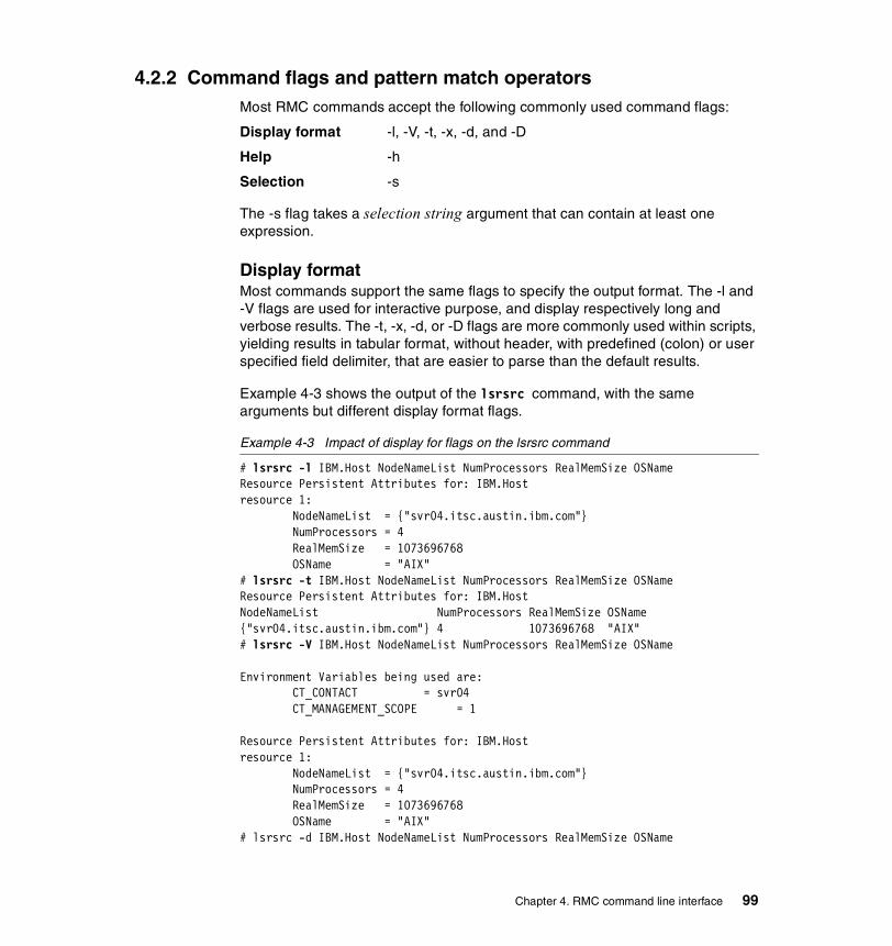
4.2.2 Command flags and pattern match operatorsMost RMC commands accept the following commonly used command flags:
Display format -l, -V, -t, -x, -d, and -D
Help -h
Selection -s
The -s flag takes a selection string argument that can contain at least one expression.
Display formatMost commands support the same flags to specify the output format. The -l and -V flags are used for interactive purpose, and display respectively long and verbose results. The -t, -x, -d, or -D flags are more commonly used within scripts, yielding results in tabular format, without header, with predefined (colon) or user specified field delimiter, that are easier to parse than the default results.
Example 4-3 shows the output of the lsrsrc command, with the same arguments but different display format flags.
Example 4-3 Impact of display for flags on the lsrsrc command
# lsrsrc -l IBM.Host NodeNameList NumProcessors RealMemSize OSNameResource Persistent Attributes for: IBM.Hostresource 1: NodeNameList = {"svr04.itsc.austin.ibm.com"} NumProcessors = 4 RealMemSize = 1073696768 OSName = "AIX"# lsrsrc -t IBM.Host NodeNameList NumProcessors RealMemSize OSNameResource Persistent Attributes for: IBM.HostNodeNameList NumProcessors RealMemSize OSName{"svr04.itsc.austin.ibm.com"} 4 1073696768 "AIX"# lsrsrc -V IBM.Host NodeNameList NumProcessors RealMemSize OSName
Environment Variables being used are: CT_CONTACT = svr04 CT_MANAGEMENT_SCOPE = 1
Resource Persistent Attributes for: IBM.Hostresource 1: NodeNameList = {"svr04.itsc.austin.ibm.com"} NumProcessors = 4 RealMemSize = 1073696768 OSName = "AIX"# lsrsrc -d IBM.Host NodeNameList NumProcessors RealMemSize OSName
Chapter 4. RMC command line interface 99

Resource Persistent Attributes for: IBM.HostNodeNameList:NumProcessors:RealMemSize:OSName:{"svr04.itsc.austin.ibm.com"}:4:1073696768:"AIX":
HelpThe -h flag displays the command syntax and usage on the standard output.
Selection When a command applies to a whole class and you want to restrict the command to a subset of the resources in the class, you must provide a selection mechanism to identify the appropriate targets. A first mechanism is to use the CT_CONTACT and CT_MANAGEMENT_SCOPE variables. To further refine the selection, you can use the -s option, followed by a selection string.
The selection string is an expression that is evaluated against each resource or class. The selection string is made of variables, operators and constants. The variables refer to persistent attributes of the target resource or class. Selection cannot be performed on dynamic attributes.
Starting from Example 4-4 to Example 4-12 on page 106, we want to know the percentage of disk space used on a set of all file systems. Therefore, we use the same settings of the CT_CONTACT and CT_MANAGEMENT_SCOPE variables throughout all these examples and changes the selection string.
First, in Example 4-4, no selection string is used, and the seven file systems in the management scope are listed.
Example 4-4 List attributes without selection
# lsrsrc IBM.FileSystem Name PercentTotUsedResource Persistent and Dynamic Attributes for: IBM.FileSystemresource 1: Name = "/work04" PercentTotUsed = 0resource 2: Name = "/opt" PercentTotUsed = 37resource 3: Name = "/tmp" PercentTotUsed = 17resource 4: Name = "/var" PercentTotUsed = 86resource 5: Name = "/usr" PercentTotUsed = 89
100 A Practical Guide for Resource Monitoring and Control (RMC)
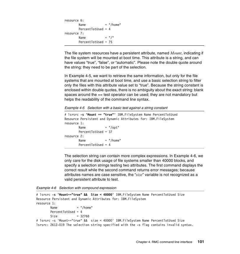
resource 6: Name = "/home" PercentTotUsed = 4resource 7: Name = "/" PercentTotUsed = 75
The file system resources have a persistent attribute, named Mount, indicating if the file system will be mounted at boot time. This attribute is a string, and can have values “true”, “false”, or “automatic”. Please note the double quote around the string: they need to be part of the selection.
In Example 4-5, we want to retrieve the same information, but only for the file systems that are mounted at boot time, and use a basic selection string to filter only the files with this attribute value set to “true”. Because the string constant is enclosed within double quotes, there is no ambiguity about the exact string: blank spaces around the == test operator can be used; they are not mandatory but helps the readability of the command line syntax.
Example 4-5 Selection with a basic test against a string constant
# lsrsrc -s 'Mount == "true"' IBM.FileSystem Name PercentTotUsedResource Persistent and Dynamic Attributes for: IBM.FileSystemresource 1: Name = "/opt" PercentTotUsed = 37resource 2: Name = "/home" PercentTotUsed = 4
The selection string can contain more complex expressions. In Example 4-6, we only care for the disk usage of file systems smaller than 40000 blocks, and specify a selection strings testing two attributes. The first command displays the correct result while the second command returns error messages; because attributes names are case sensitive, the “size” variable is not recognized as a valid persistent attribute to test.
Example 4-6 Selection with compound expression
# lsrsrc -s 'Mount=="true" && Size < 40000' IBM.FileSystem Name PercentTotUsed SizeResource Persistent and Dynamic Attributes for: IBM.FileSystemresource 1: Name = "/home" PercentTotUsed = 4 Size = 32768# lsrsrc -s 'Mount=="true" && size < 40000' IBM.FileSystem Name PercentTotUsed Sizelsrsrc: 2612-019 The selection string specified with the -s flag contains invalid syntax.
Chapter 4. RMC command line interface 101
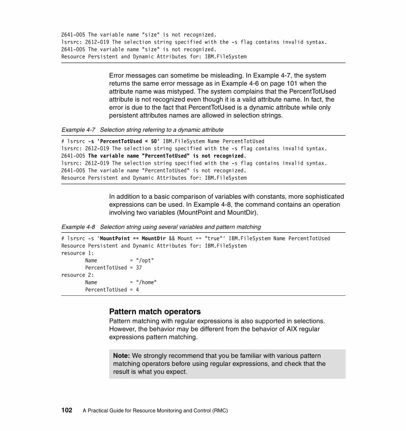
2641-005 The variable name "size" is not recognized.lsrsrc: 2612-019 The selection string specified with the -s flag contains invalid syntax.2641-005 The variable name "size" is not recognized.Resource Persistent and Dynamic Attributes for: IBM.FileSystem
Error messages can sometime be misleading. In Example 4-7, the system returns the same error message as in Example 4-6 on page 101 when the attribute name was mistyped. The system complains that the PercentTotUsed attribute is not recognized even though it is a valid attribute name. In fact, the error is due to the fact that PercentTotUsed is a dynamic attribute while only persistent attributes names are allowed in selection strings.
Example 4-7 Selection string referring to a dynamic attribute
# lsrsrc -s 'PercentTotUsed < 50' IBM.FileSystem Name PercentTotUsedlsrsrc: 2612-019 The selection string specified with the -s flag contains invalid syntax.2641-005 The variable name "PercentTotUsed" is not recognized.lsrsrc: 2612-019 The selection string specified with the -s flag contains invalid syntax.2641-005 The variable name "PercentTotUsed" is not recognized.Resource Persistent and Dynamic Attributes for: IBM.FileSystem
In addition to a basic comparison of variables with constants, more sophisticated expressions can be used. In Example 4-8, the command contains an operation involving two variables (MountPoint and MountDir).
Example 4-8 Selection string using several variables and pattern matching
# lsrsrc -s 'MountPoint == MountDir && Mount == "true"' IBM.FileSystem Name PercentTotUsedResource Persistent and Dynamic Attributes for: IBM.FileSystemresource 1: Name = "/opt" PercentTotUsed = 37resource 2: Name = "/home" PercentTotUsed = 4
Pattern match operatorsPattern matching with regular expressions is also supported in selections. However, the behavior may be different from the behavior of AIX regular expressions pattern matching.
Note: We strongly recommend that you be familiar with various pattern matching operators before using regular expressions, and check that the result is what you expect.
102 A Practical Guide for Resource Monitoring and Control (RMC)

There are two pattern match operators, =~ and =?, and two not pattern match operators, !~ and ~?. The =~ and !~ operators apply to operators using the same extended regular expression syntax as the AIX awk or grep commands do, while =? and !? apply to operands using the SQL-like syntax.
The =~ and !~ operators match substrings, while the SQL-like =? and !? operators match full strings.
When using the extended regular expression operators =~ and !~ with wild cards, you should use:
� The dot (.) to match exactly one character.
� The star (*) to match zero or more occurrences of the preceding characters.
With the SQL-like syntax operators, =~ and !~, you should use the following wild card characters:
� The percent sign (%) matches zero or more characters.
� The underscore (_) matches exactly one character.
� The percentage and underscore characters can be quoted with the pound sign (#) to override their special meaning.
Example 4-9 shows that mixing the SQL-like pattern match operator =? with either the AIX regular expression syntax or the SQL-like syntax wild characters returns different outputs
Example 4-9 Mixing supported syntax with pattern matching operators
# lsrsrc -s 'Mount =? "t.*"' IBM.FileSystem Name MountResource Persistent Attributes for: IBM.FileSystem# lsrsrc -s 'Mount =? "t%"' IBM.FileSystem Name MountResource Persistent Attributes for: IBM.FileSystemresource 1: Name = "/opt" Mount = "true"resource 2: Name = "/home" Mount = "true"
We will finish this section about selection string with an example showing the different behavior of the =~, =?, !~, and !? operators.
Note: We recommend that you do not mix operators of one category (regexp or SQL) with wild cards of the other category.
Chapter 4. RMC command line interface 103
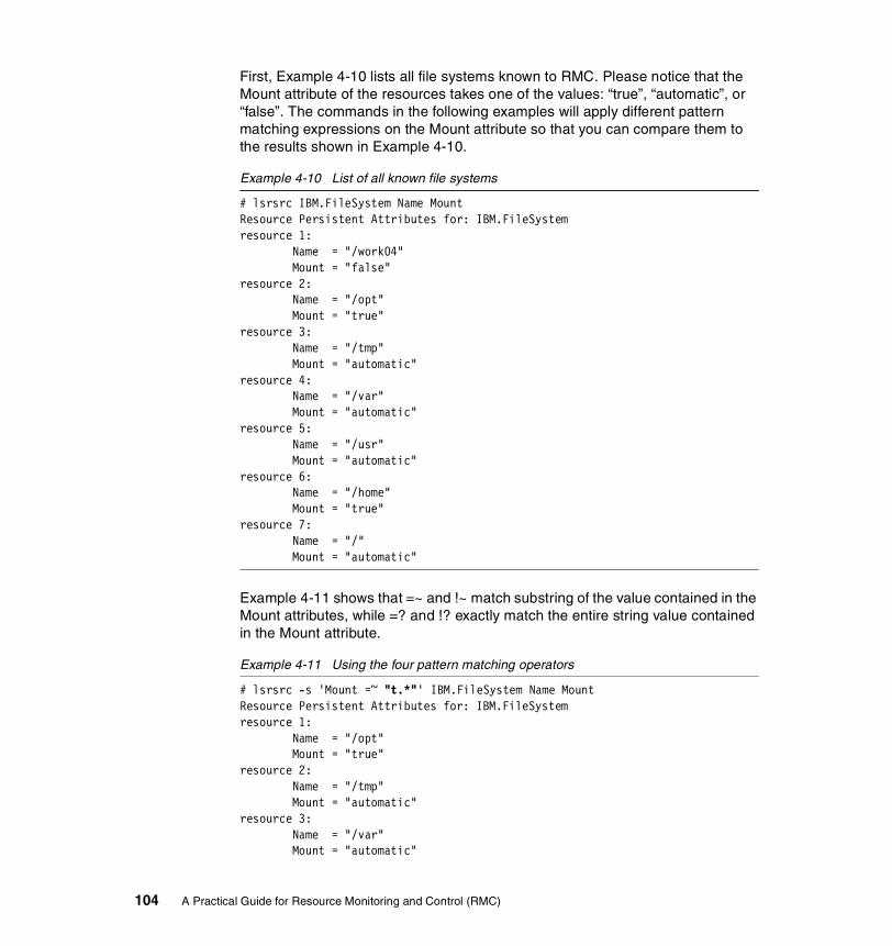
First, Example 4-10 lists all file systems known to RMC. Please notice that the Mount attribute of the resources takes one of the values: “true”, “automatic”, or “false”. The commands in the following examples will apply different pattern matching expressions on the Mount attribute so that you can compare them to the results shown in Example 4-10.
Example 4-10 List of all known file systems
# lsrsrc IBM.FileSystem Name MountResource Persistent Attributes for: IBM.FileSystemresource 1: Name = "/work04" Mount = "false"resource 2: Name = "/opt" Mount = "true"resource 3: Name = "/tmp" Mount = "automatic"resource 4: Name = "/var" Mount = "automatic"resource 5: Name = "/usr" Mount = "automatic"resource 6: Name = "/home" Mount = "true"resource 7: Name = "/" Mount = "automatic"
Example 4-11 shows that =~ and !~ match substring of the value contained in the Mount attributes, while =? and !? exactly match the entire string value contained in the Mount attribute.
Example 4-11 Using the four pattern matching operators
# lsrsrc -s 'Mount =~ "t.*"' IBM.FileSystem Name MountResource Persistent Attributes for: IBM.FileSystemresource 1: Name = "/opt" Mount = "true"resource 2: Name = "/tmp" Mount = "automatic"resource 3: Name = "/var" Mount = "automatic"
104 A Practical Guide for Resource Monitoring and Control (RMC)
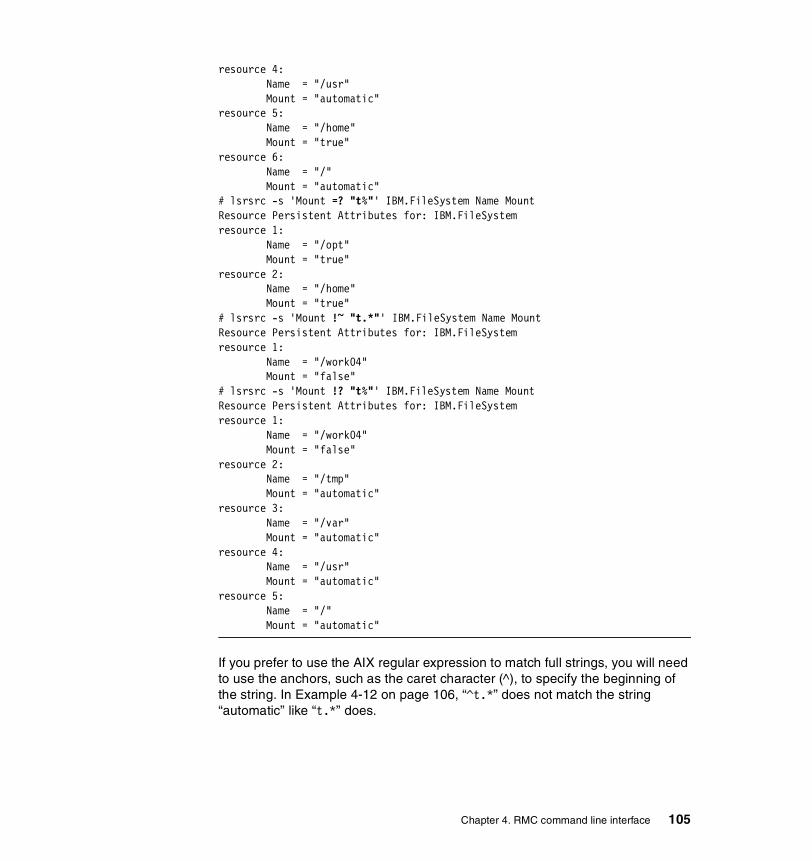
resource 4: Name = "/usr" Mount = "automatic"resource 5: Name = "/home" Mount = "true"resource 6: Name = "/" Mount = "automatic"# lsrsrc -s 'Mount =? "t%"' IBM.FileSystem Name MountResource Persistent Attributes for: IBM.FileSystemresource 1: Name = "/opt" Mount = "true"resource 2: Name = "/home" Mount = "true"# lsrsrc -s 'Mount !~ "t.*"' IBM.FileSystem Name MountResource Persistent Attributes for: IBM.FileSystemresource 1: Name = "/work04" Mount = "false"# lsrsrc -s 'Mount !? "t%"' IBM.FileSystem Name MountResource Persistent Attributes for: IBM.FileSystemresource 1: Name = "/work04" Mount = "false"resource 2: Name = "/tmp" Mount = "automatic"resource 3: Name = "/var" Mount = "automatic"resource 4: Name = "/usr" Mount = "automatic"resource 5: Name = "/" Mount = "automatic"
If you prefer to use the AIX regular expression to match full strings, you will need to use the anchors, such as the caret character (^), to specify the beginning of the string. In Example 4-12 on page 106, “^t.*” does not match the string “automatic” like “t.*” does.
Chapter 4. RMC command line interface 105

Example 4-12 Use of ^ in extended regular expression
# lsrsrc -s 'Mount =~ "^t.*"' IBM.FileSystem Name MountResource Persistent Attributes for: IBM.FileSystemresource 1: Name = "/WT" Mount = "true"resource 2: Name = "/AIX_updates" Mount = "true"resource 3: Name = "/opt" Mount = "true"resource 4: Name = "/home" Mount = "true"
For a complete list of all expressions operators supported by RMC, please refer to Chapter 3 in the IBM RSCT for AIX: Guide and Reference, SA22-7889.
4.2.3 Persistent property value fileThe last feature we present in this section is the file format called Resource_Data_Input. Files with this format can be used to pass resource and resource classes property values, either to define new resources or to change persistent property values.
Only four commands uses this file format. The lsrsrcdef and lsactdef commands, which respectively list resource (class) definition and action definitions, can generate an output using Resource_Data_Input when used with the -i flag. You can redirect the command’s standard output to a file, then edit the file. If the -f flag is specified, the mkrsrc and chrsrc commands use the file name specified on the command line argument as their input.
4.3 A peer domain cluster setupThis section explains how to configure a peer domain cluster, described in Section 4.1, “Test environment” on page 94. All examples in Section 4.4, “SRC commands” on page 112 and later assume this configuration.
However, if you do not intend to use peer domain clusters and are not interested in cluster configuration commands, you can skip this section.
106 A Practical Guide for Resource Monitoring and Control (RMC)
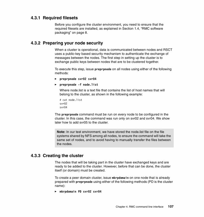
4.3.1 Required filesetsBefore you configure the cluster environment, you need to ensure that the required filesets are installed, as explained in Section 1.4, “RMC software packaging” on page 8.
4.3.2 Preparing your node securityWhen a cluster is operational, data is communicated between nodes and RSCT uses a public-key based security mechanism to authenticate the exchange of messages between the nodes. The first step in setting up the cluster is to exchange public keys between nodes that are to be clustered together.
To execute this step, issue preprpnode on all nodes using either of the following methods:
� preprpnode svr02 svr04
� preprpnode -f node.list
Where node.list is a text file that contains the list of host names that will belong to the cluster, as shown in the following example:
# cat node.listsvr02svr04
The preprpnode command must be run on every node to be configured in the cluster. In this case, the command was run only on svr02 and svr04. We show later how to add svr05 to the cluster.
4.3.3 Creating the clusterThe nodes that will be taking part in the cluster have exchanged keys and are ready to be added to the cluster. However, before that can be done, the cluster itself (or domain) must be created.
To create a peer domain cluster, issue mkrpdomain on one node that is already prepared with preprpnode using either of the following methods (PD is the cluster name):
� mkrpdomain PD svr02 svr04
Note: In our test environment, we have stored the node.list file on the file systems shared by NFS among all nodes, to ensure the command will take the same set of nodes, and to avoid having to manually transfer the files between the nodes.
Chapter 4. RMC command line interface 107
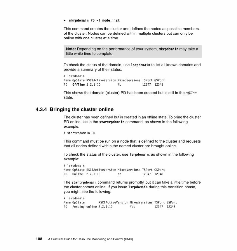
� mkrpdomain PD -f node.list
This command creates the cluster and defines the nodes as possible members of the cluster. Nodes can be defined within multiple clusters but can only be online with one cluster at a time.
To check the status of the domain, use lsrpdomain to list all known domains and provide a summary of their status:
# lsrpdomainName OpState RSCTActiveVersion MixedVersions TSPort GSPortPD Offline 2.2.1.10 No 12347 12348
This shows that domain (cluster) PD has been created but is still in the offline state.
4.3.4 Bringing the cluster onlineThe cluster has been defined but is created in an offline state. To bring the cluster PD online, issue the startrpdomain command, as shown in the following example:
# startrpdomain PD
This command must be run on a node that is defined to the cluster and requests that all nodes defined within the named cluster are brought online.
To check the status of the cluster, use lsrpdomain, as shown in the following example:
# lsrpdomainName OpState RSCTActiveVersion MixedVersions TSPort GSPortPD Online 2.2.1.10 No 12347 12348
The startrpdomain command returns promptly, but it can take a little time before the cluster comes online. If you issue lsrpdomain during this transition phase, you might see the following:
# lsrpdomainName OpState RSCTActiveVersion MixedVersions TSPort GSPortPD Pending online 2.2.1.10 Yes 12347 12348
Note: Depending on the performance of your system, mkrpdomain may take a little while time to complete.
108 A Practical Guide for Resource Monitoring and Control (RMC)
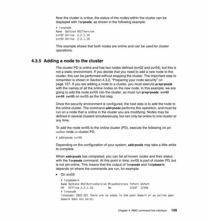
Now the cluster is online, the status of the nodes within the cluster can be displayed with lsrpnode, as shown in the following example:
# lsrpnodeName OpState RSCTVersionsvr02 Online 2.2.1.10svr04 Online 2.2.1.10
This example shows that both nodes are online and can be used for cluster operations.
4.3.5 Adding a node to the clusterThe cluster PD is online and has two nodes defined (svr02 and svr04), but this is not a static environment. If you decide that you need to add a new node to the cluster, this can be performed without stopping the cluster. The important step to remember is shown in Section 4.3.2, “Preparing your node security” on page 107. If you are adding a node to a cluster, you must execute preprpnode with the names of all the online nodes on the new node. In this example, we are going to add the node svr05 into the cluster, so must run preprpnode svr02 svr04 svr05 on svr05 as the first step.
Once the security environment is configured, the next step is to add the node to the online cluster. The command addrpnode performs this operation, and must be run on a node that is online in the cluster you are modifying. Nodes may be defined in several clusters simultaneously, but can only be online to one cluster at any time.
To add the node svr05 to the online cluster (PD), execute the following on an online node in cluster PD.
# addrpnode svr05
Depending on the configuration of your system, addrpnode may take a little while to complete.
When addrpnode has completed, you can list all known nodes and their status with the lsrpnode command. At this point in time, svr05 is part of cluster PD, but is not yet online. This means that the output of lsrpnode and lsrpdomain depends on where the commands are run, for example:
� On svr05
# lsrpdomainName OpState RSCTActiveVersion MixedVersions TSPort GSPortPD Offline 2.2.1.10 No 12347 12348# lsrpnodelsrpnode: 2602-021 There are no nodes in the peer domain or an online peer domain does not exist.
Chapter 4. RMC command line interface 109

� On svr04
# lsrpdomainName OpState RSCTActiveVersion MixedVersions TSPort GSPortPD Online 2.2.1.10 No 12347 12348# lsrpnodeName OpState RSCTVersionsvr05 Offline 2.2.1.10svr02 Online 2.2.1.10svr04 Online 2.2.1.10
Both of the above examples demonstrate the correct behavior and tell you the importance of using the correct commands at the correct time on the correct node.
4.3.6 Bringing a node onlineThe node svr05 is now defined in cluster PD but is not yet online. To bring a node online, you can use the command startrpnode and this must be executed on an online node in the cluster as follows:
# startrpnode svr05
The startrpnode command returns promptly, but it may take a short while before the node is brought online.
To show the status of the cluster and nodes, do the following task:
# lsrpdomainName OpState RSCTActiveVersion MixedVersions TSPort GSPortPD Online 2.2.1.10 No 12347 12348# lsrpnodeName OpState RSCTVersionsvr05 Online 2.2.1.10svr02 Online 2.2.1.10svr04 Online 2.2.1.10
4.3.7 Stopping (offline) a node in the clusterThe stoprpnode command can be used to put a node in the offline state. This command can be executed from any online node in the cluster as follows. This example was run on svr04 and, if run on svr05, the final lsrpnode would fail (correctly), because svr05 is not online to a cluster anymore.
Note: If you have a number of nodes to bring online in the cluster, you can use the startrpdomain command to bring them all online without having to specify the node names.
110 A Practical Guide for Resource Monitoring and Control (RMC)

For example:
# lsrpnodeName OpState RSCTVersionsvr05 Online 2.2.1.10svr02 Online 2.2.1.10svr04 Online 2.2.1.10# stoprpnode svr05# lsrpnodeName OpState RSCTVersionsvr05 Offline 2.2.1.10svr02 Online 2.2.1.10svr04 Online 2.2.1.10
The stoprpnode command returns promptly, but it may take a short while before the node is brought offline.
4.3.8 Removing a node from the clusterIf you must remove a node from the cluster, the node must first be in the offline state, and then it can be removed with the rmrpnode command. This must be executed on an online node of the cluster:
# rmrpnode svr05# lsrpnodeName OpState RSCTVersionsvr02 Online 2.2.1.10svr04 Online 2.2.1.10
Depending on the configuration of your system, rmrpnode may take a little while to complete.
4.3.9 Stopping (offline) a clusterThe stoprpdomain command is used to take all the online nodes of a cluster offline. It must be run on an online node, as shown in the following example:
# stoprpdomain PD# lsrpdomainName OpState RSCTActiveVersion MixedVersions TSPort GSPortPD Offline 2.2.1.10 Yes 12347 12348
The cluster configuration is preserved after the cluster status is changed to offline.
Chapter 4. RMC command line interface 111
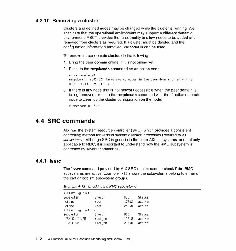
4.3.10 Removing a clusterClusters and defined nodes may be changed while the cluster is running. We anticipate that the operational environment may support a different dynamic environment. RSCT provides the functionality to allow nodes to be added and removed from clusters as required. If a cluster must be deleted and the configuration information removed, rmrpdomain can be used.
To remove a peer domain cluster, do the following:
1. Bring the peer domain online, if it is not online yet.
2. Execute the rmrpdomain command on an online node:
# rmrpdomain PDrmrpdomain: 2602-021 There are no nodes in the peer domain or an online peer domain does not exist.
3. If there is any node that is not network accessible when the peer domain is being removed, execute the rmrpdomain command with the -f option on each node to clean up the cluster configuration on the node:
# rmrpdomain -f PD
4.4 SRC commandsAIX has the system resource controller (SRC), which provides a consistent controlling method for various system daemon processes (referred to as subsystems). Although SRC is generic to the other AIX subsystems, and not only applicable to RMC, it is important to understand how the RMC subsystem is controlled by several commands.
4.4.1 lssrcThe lssrc command provided by AIX SRC can be used to check if the RMC subsystems are active. Example 4-13 shows the subsystems belong to either of the rsct or rsct_rm subsystem groups.
Example 4-13 Checking the RMC subsystems
# lssrc -g rsctSubsystem Group PID Status ctcas rsct 17802 active ctrmc rsct 24950 active# lssrc -g rsct_rmSubsystem Group PID Status IBM.ConfigRM rsct_rm 11618 active IBM.ERRM rsct_rm 21350 active
112 A Practical Guide for Resource Monitoring and Control (RMC)
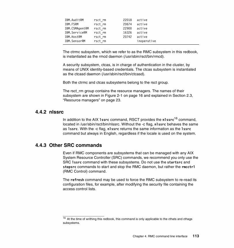
IBM.AuditRM rsct_rm 22018 active IBM.FSRM rsct_rm 20674 active IBM.CSMAgentRM rsct_rm 22900 active IBM.ServiceRM rsct_rm 16326 active IBM.HostRM rsct_rm 20742 active IBM.SensorRM rsct_rm inoperative
The ctrmc subsystem, which we refer to as the RMC subsystem in this redbook, is instantiated as the rmcd daemon (/usr/sbin/rsct/bin/rmcd).
A security subsystem, ctcas, is in charge of authentication in the cluster, by means of UNIX identity-based credentials. The ctcas subsystem is instantiated as the ctcasd daemon (/usr/sbin/rsct/bin/ctcasd).
Both the ctrmc and ctcas subsystems belong to the rsct group.
The rsct_rm group contains the resource managers. The names of their subsystem are shown in Figure 2-1 on page 16 and explained in Section 2.3, “Resource managers” on page 23.
4.4.2 nlssrcIn addition to the AIX lssrc command, RSCT provides the nlssrc16 command, located in /usr/sbin/rsct/bin/nlssrc. Without the -c flag, nlssrc behaves the same as lssrc. With the -c flag, nlssrc returns the same information as the lssrc command but always in English, regardless if the locale is used on the system.
4.4.3 Other SRC commandsEven if RMC components are subsystems that can be managed with any AIX System Resource Controller (SRC) commands, we recommend you only use the SRC lssrc command with these subsystems. Do not use the startsrc and stopsrc commands to start and stop the RMC daemon, but rather the rmcctrl (RMC Control) command.
The refresh command may be used to force the RMC subsystem to re-read its configuration files, for example, after modifying the security file containing the access control lists.
16 At the time of writhing this redbook, this command is only applicable to the cthats and cthags subsystems.
Chapter 4. RMC command line interface 113

4.5 RSCT commandsRSCT provides the user with many commands to control, for example, the Group Services or the Topology Services. We present, in this redbook, the RSCT command rmcctrl only as it is related to resource monitoring and control.
The rmcctrl command manages both the RMC subsystem and the resource managers subsystem. Depending on the flags passed to the command, it will add or remove the RMC subsystem to or from the subsystem object class, and start or stop the subsystems.
During the AIX installation, the rmcctrl-a command is performed automatically (RSCT is part of the filesets installed by default), and the following entry will be added in the /etc/inittab:
# grep ctrmc /etc/inittabctrmc:2:once:/usr/bin/startsrc -s ctrmc > /dev/console 2>&1
Therefore, the RMC subsystem is started by default upon every reboot. There is no need to perform any action to manually start it in normal operation.
The -s and -k flags start and stop the ctrmc only. They have no action on the security subsystem ctcas or on resource managers. Once the ctrmc subsystem is started, it will start the other components when it needs them. For example, the ctcas and IBM.ERRM subsystems will be immediately started, while the IBM.HostRM subsystem will only be started when there is a need to interact with one of the resources or classes it manages.
Because the ctcas and IBM.ERRM subsystems are started by ctrmc when needed, there is no flag in the rmcctrl command to start one of these subsystems.
Both the -K and -z options stops RMC and the resource managers, but the former is asynchronous while the later is synchronous. With -z, the command will not return before all subsystems have actually stopped. the -K flag is therefore more suitable for interactive use, while the -z options is useful when the rmcctrl command is used in scripts where you must be sure that all daemons are stopped before executing another action.
4.6 RMC commandsBecause the RMC subsystem is the generic core of RSCT Resource Monitoring and Control, it provides several commands that handle resources classes and resources generally (we refer to these commands as generic RMC commands).
114 A Practical Guide for Resource Monitoring and Control (RMC)

All commands described in Section 4.7, “Sensor commands” on page 122 and later are specific to one resource class.
There are five categories of generic RMC commands:
Creation mkrsrc
Display lsrsrc, lsrsrcdef, and lsactdef
Modification chrsrc
Deletion rmrsrc
Refresh refrsrc
The mkrsrc, lsactdef, chrsrc, and rmrsrc commands are described in the IBM RSCT for AIX: Technical Reference, SA22-7890. For all resources that can be created by an end user, RMC provides a resource specific command (for example: mkcondition and mksensor), which is easier to use than the generic RMC commands. We therefore recommend you use the resource specific commands only.
In this section, we describe the use of lsrsrc, lsrsrcdef, and refrsrc.
4.6.1 lsrsrcThis is the most widely used of all RMC commands. We already presented several examples of lsrsrc in Section 4.2, “Common variables and command flags” on page 95. The lsrsrc command lists the attributes (and their values) of resources and resources classes.
Classes and resources can have a large number of attributes, and the default behavior of lsrsrc is to only display a subset of them. It is important to understand the effect of flags on the returned result.
The first argument of lsrsrc is a resource class name. By default, the result will relate to resources in this class. You need to specify the -c flag to retrieve class attributes and values. Example 4-14 on page 116 shows that the IBM.PagingDevice class has no public attribute, while resources in this class have three public attributes. This example also shows that server svr01 has only one paging space defined on logical volume /dev/hd6.
Note: It may not always be obvious to guess the meaning of an attribute from only its name. Please refer to the IBM RSCT for AIX: Guide and Reference, SA22-7889 for a detailed description of supported attributes.
Chapter 4. RMC command line interface 115
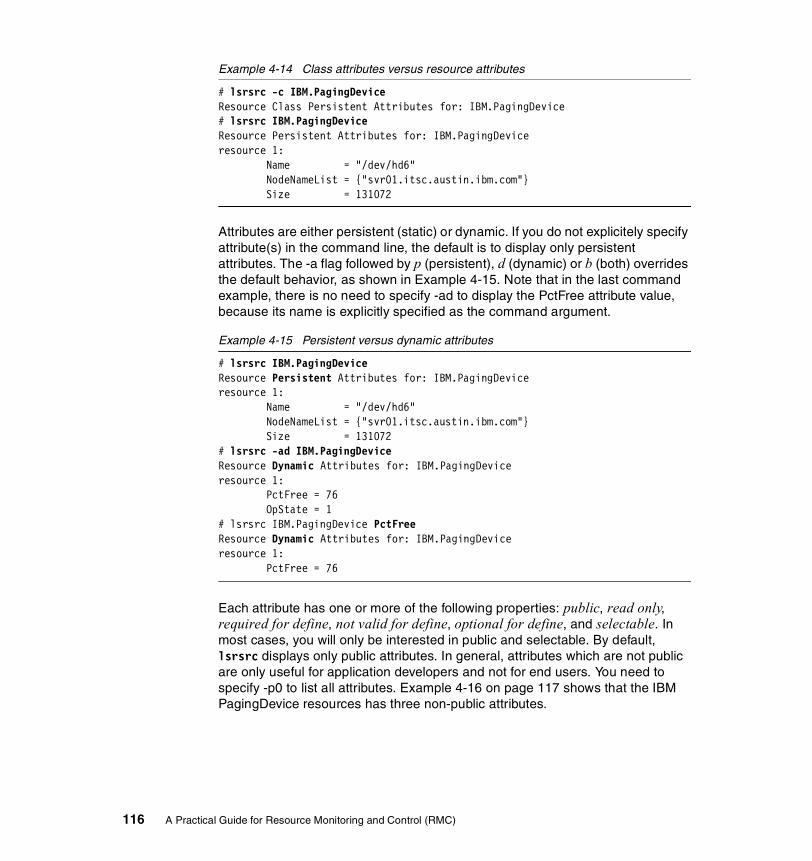
Example 4-14 Class attributes versus resource attributes
# lsrsrc -c IBM.PagingDeviceResource Class Persistent Attributes for: IBM.PagingDevice# lsrsrc IBM.PagingDeviceResource Persistent Attributes for: IBM.PagingDeviceresource 1: Name = "/dev/hd6" NodeNameList = {"svr01.itsc.austin.ibm.com"} Size = 131072
Attributes are either persistent (static) or dynamic. If you do not explicitely specify attribute(s) in the command line, the default is to display only persistent attributes. The -a flag followed by p (persistent), d (dynamic) or b (both) overrides the default behavior, as shown in Example 4-15. Note that in the last command example, there is no need to specify -ad to display the PctFree attribute value, because its name is explicitly specified as the command argument.
Example 4-15 Persistent versus dynamic attributes
# lsrsrc IBM.PagingDeviceResource Persistent Attributes for: IBM.PagingDeviceresource 1: Name = "/dev/hd6" NodeNameList = {"svr01.itsc.austin.ibm.com"} Size = 131072# lsrsrc -ad IBM.PagingDeviceResource Dynamic Attributes for: IBM.PagingDeviceresource 1: PctFree = 76 OpState = 1# lsrsrc IBM.PagingDevice PctFreeResource Dynamic Attributes for: IBM.PagingDeviceresource 1: PctFree = 76
Each attribute has one or more of the following properties: public, read only, required for define, not valid for define, optional for define, and selectable. In most cases, you will only be interested in public and selectable. By default, lsrsrc displays only public attributes. In general, attributes which are not public are only useful for application developers and not for end users. You need to specify -p0 to list all attributes. Example 4-16 on page 117 shows that the IBM PagingDevice resources has three non-public attributes.
116 A Practical Guide for Resource Monitoring and Control (RMC)

Example 4-16 Default (public) versus all attributes
# lsrsrc IBM.PagingDeviceResource Persistent Attributes for: IBM.PagingDeviceresource 1: Name = "/dev/hd6" NodeNameList = {"svr01.itsc.austin.ibm.com"} Size = 131072# lsrsrc -p0 IBM.PagingDeviceResource Persistent Attributes for: IBM.PagingDeviceresource 1: Name = "/dev/hd6" ResourceHandle = "0x600a 0xffff 0x383530da 0x6abe1f4f 0x0e337e5c 0xb3a9cbd6" Variety = 1 NodeNameList = {"svr01.itsc.austin.ibm.com"} NodeIDs = {4050197154541477711} Size = 131072
In this example, we have chosen a resource class that only contains one resource. In general, this will not be the case, especially in a cluster environment, but you are most likely to be interested in a subset of the resources only. You have to use the -s “selection string” flag to select this subset. We have provided several examples of using this flag in Section 4.2, “Common variables and command flags” on page 95. The attributes that can be used in the selection string are those that have the selectable property.
One of the non public attributes that can be useful to end users is the ResourceHandle. All resources, whatever the class they belong to, have a ResourceHandle, which uniquely identifies this resource within the cluster. When dealing with many resources, it can be time consuming and error prone to repeat the same complex selection to refer to one object. Retrieving the ResourceHandle of this resource once and for all, and reusing it each time you need to refer to this very resource, will improve your efficiency. This can be specially helpful if you write scripts calling RMC commands.
Example 4-17 on page 118 shows how to store the ResourceHandle of a resource in a shell variable to be reused by other commands. The first command stores the value of the ResourceHandle in the RHdl variable. Note that the command lines spread over three lines, one of which is just a selection string. The echo command proves that the variable is correctly set. The mkcondition command reuses the RHdl shell variable to create a condition, and lscondition proves that the previous command was successful.
Chapter 4. RMC command line interface 117
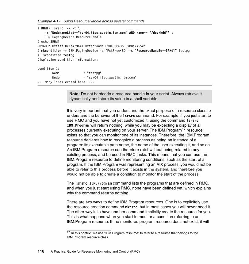
Example 4-17 Using ResourceHandle across several commands
# RHdl=`lsrsrc -x -t \-s 'NodeNameList=="svr04.itsc.austin.ibm.com" AND Name== "/dev/hd6"' \IBM.PagingDevice ResourceHandle`
# echo $RHdl"0x600a 0xffff 0x1e479641 0xfea2a4dc 0x0e338635 0x88a7455e"# mkcondition -r IBM.PagingDevice -e "PctFree<50" -s "ResourceHandle==$RHdl" testpg# lscondition testpgDisplaying condition information:
condition 1: Name = "testpg" Node = "svr04.itsc.austin.ibm.com"... many lines erased here ....
It is very important that you understand the exact purpose of a resource class to understand the behavior of the lsrsrc command. For example, if you just start to use RMC and you have not yet customized it, using the command lsrsrc IBM.Program will return nothing, while you may be expecting a display of all processes currently executing on your server. The IBM.Program17 resource exists so that you can monitor one of its instances. Therefore, the IBM.Program resource declares how to recognize a process as being an instance of a program: its executable path name, the name of the user executing it, and so on. An IBM.Program resource can therefore exist without being related to any existing process, and be used in RMC tasks. This means that you can use the IBM.Program resource to define monitoring conditions, such as the start of a program. If the IBM.Program was representing an AIX process, you would not be able to refer to this process before it exists in the system, and therefore you would not be able to create a condition to monitor the start of the process.
The lsrsrc IBM.Program command lists the programs that are defined in RMC, and when you just start using RMC, none have been defined yet, which explains why the command returns nothing.
There are two ways to define IBM.Program resources. One is to explicitely use the resource creation command mkrsrc, but in most cases you will never need it. The other way is to have another command implicitly create the resource for you. This is what happens when you start to monitor a condition referring to an IBM.Program resource. If the monitored program resource does not exist, it will
Note: Do not hardcode a resource handle in your script. Always retrieve it dynamically and store its value in a shell variable.
17 In this context, we use “IBM.Program resource” to refer to a resource that belongs to the IBM.Program resource class.
118 A Practical Guide for Resource Monitoring and Control (RMC)
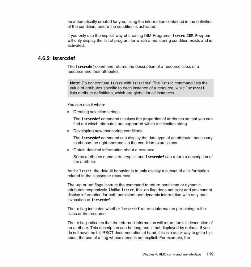
be automatically created for you, using the information contained in the definition of the condition, before the condition is activated.
If you only use the implicit way of creating IBM.Programs, lsrsrc IBM.Program will only display the list of program for which a monitoring condition exists and is activated.
4.6.2 lsrsrcdefThe lsrsrcdef command returns the description of a resource class or a resource and their attributes.
You can use it when:
� Creating selection strings
The lsrsrcdef command displays the properties of attributes so that you can find out which attributes are supported within a selection string.
� Developing new monitoring conditions
The lsrsrcdef command can display the data type of an attribute, necessary to choose the right operands in the condition expressions.
� Obtain detailed information about a resource
Some attributes names are cryptic, and lsrsrcdef can return a description of the attribute.
As for lsrsrc, the default behavior is to only display a subset of all information related to the classes or resources.
The -ap or -ad flags instruct the command to return persistent or dynamic attributes respectively. Unlike lsrsrc, the -ab flag does not exist and you cannot display information for both persistent and dynamic information with only one invocation of lsrsrcdef.
The -c flag indicates whether lsrsrcdef returns information pertaining to the class or the resource.
The -e flag indicates that the returned information will return the full description of an attribute. This description can be long and is not displayed by default. If you do not have the full RSCT documentation at hand, this is a quick way to get a hint about the use of a flag whose name is not explicit. For example, the
Note: Do not confuse lsrsrc with lsrsrcdef. The lsrsrc command lists the value of attributes specific to each instance of a resource, while lsrsrcdef lists attribute definitions, which are global for all instances.
Chapter 4. RMC command line interface 119
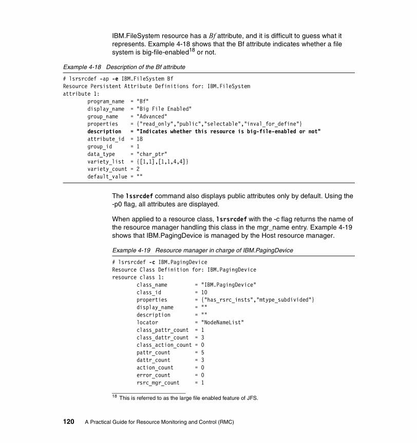
IBM.FileSystem resource has a Bf attribute, and it is difficult to guess what it represents. Example 4-18 shows that the Bf attribute indicates whether a file system is big-file-enabled18 or not.
Example 4-18 Description of the Bf attribute
# lsrsrcdef -ap -e IBM.FileSystem BfResource Persistent Attribute Definitions for: IBM.FileSystemattribute 1: program_name = "Bf" display_name = "Big File Enabled" group_name = "Advanced" properties = {"read_only","public","selectable","inval_for_define"} description = "Indicates whether this resource is big-file-enabled or not" attribute_id = 18 group_id = 1 data_type = "char_ptr" variety_list = {[1,1],[1,1,4,4]} variety_count = 2 default_value = ""
The lssrcdef command also displays public attributes only by default. Using the -p0 flag, all attributes are displayed.
When applied to a resource class, lsrsrcdef with the -c flag returns the name of the resource manager handling this class in the mgr_name entry. Example 4-19 shows that IBM.PagingDevice is managed by the Host resource manager.
Example 4-19 Resource manager in charge of IBM.PagingDevice
# lsrsrcdef -c IBM.PagingDeviceResource Class Definition for: IBM.PagingDeviceresource class 1: class_name = "IBM.PagingDevice" class_id = 10 properties = {"has_rsrc_insts","mtype_subdivided"} display_name = "" description = "" locator = "NodeNameList" class_pattr_count = 1 class_dattr_count = 3 class_action_count = 0 pattr_count = 5 dattr_count = 3 action_count = 0 error_count = 0 rsrc_mgr_count = 1
18 This is referred to as the large file enabled feature of JFS.
120 A Practical Guide for Resource Monitoring and Control (RMC)
rsrc_mgrs 1: mgr_name = "IBM.HostRM" first_key = 1 last_key = 1
4.6.3 refrsrcEach resource manager maintains a list of the resources it knows. A resource is a virtual software object that represents one real object in the cluster. For example, there is one IBM.Filesystem resource for each JFS or JFS2 file system that has been defined in your system.
The RSCT Resource Monitoring and Control architecture does not specify how a resource manager has to manage the association between the virtual resource and the real object it represents. In particular, the architecture does not impose real-time constraints or event driven implementation of the resource managers.
As a consequence, there may be some delay between the creation or modification of a real resource and the update of the attributes of the corresponding resource. For example, the Sensor resource manager default refresh rate is once every 60 seconds.
The refresh command takes the name of a resource class as its parameter. It forces the resource manager owning this class to detect any changes in the configuration of resources in this class.
The lsrsrc -x command returns all the resource class names, as shown in the following example:
# lsrsrc -x"IBM.Association""IBM.ATMDevice""IBM.AuditLog""IBM.AuditLogTemplate""IBM.Condition""IBM.EthernetDevice"… many lines are erased …
However, the resource class name is enclosed by the double-quote characters in the output. To chop the double-quote characters returned by lsrsrc around the resource class names, you can use sed, as shown in the following example:
# for i in `lsrsrc -x | sed 's/\"//g'`do
echo $idone
Chapter 4. RMC command line interface 121

Example 4-20 shows how to refresh all resource classes using refrsrc in the do loop.
Example 4-20 Refreshing classes with eval
# for i in `lsrsrc -x | sed 's/\"//g'`do
refrsrc -V $idoneRefreshing resource class: IBM.AssociationRefreshing resource class: IBM.ATMDeviceRefreshing resource class: IBM.AuditLogRefreshing resource class: IBM.AuditLogTemplate... many lines erased here ...
Because you cannot set the resource managers refresh rate, if you are in an environment where resource configurations change often, we recommend that you force a refresh of the classes if you execute several commands relying on an accurate list of resources within a short time interval. This can be the case, for example, in a script that would modify your configuration (adding file system, changing TCP/IP adapters settings, and so on) and use RMC commands.
4.7 Sensor commandsWhen you want to monitor a part of the AIX environment for which RMC does not provide a predefined resource class or attribute, you can create your own resource, called a sensor, using the Sensor resource manager. A sensor is a command that will be periodically executed, returning a set of values that can be monitored with the Event Response resource manager.
The Sensor resource manager provides four commands to list, create, modify or remove sensors; lssensor, mksensor, chsensor, and rmsensor.
Section 5.2, “Advanced monitoring” on page 156 contains detailed examples of the use of these sensor commands.
A sensor refers to a program by the full path name. Therefore, a sensor must be defined on the node where this program is stored. Usually, this program is not provided by the operating system, but is a user defined script.
Note: In our test environment, all scripts used as sensors are stored in the NFS file systems shared among all nodes in the cluster, so that the sensor can be activated on any node without having to copy executable files across the cluster.
122 A Practical Guide for Resource Monitoring and Control (RMC)
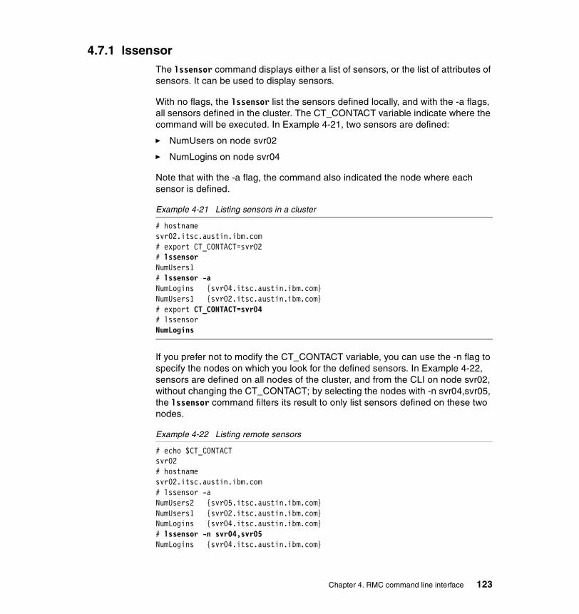
4.7.1 lssensorThe lssensor command displays either a list of sensors, or the list of attributes of sensors. It can be used to display sensors.
With no flags, the lssensor list the sensors defined locally, and with the -a flags, all sensors defined in the cluster. The CT_CONTACT variable indicate where the command will be executed. In Example 4-21, two sensors are defined:
� NumUsers on node svr02
� NumLogins on node svr04
Note that with the -a flag, the command also indicated the node where each sensor is defined.
Example 4-21 Listing sensors in a cluster
# hostnamesvr02.itsc.austin.ibm.com# export CT_CONTACT=svr02# lssensorNumUsers1# lssensor -aNumLogins {svr04.itsc.austin.ibm.com}NumUsers1 {svr02.itsc.austin.ibm.com}# export CT_CONTACT=svr04# lssensorNumLogins
If you prefer not to modify the CT_CONTACT variable, you can use the -n flag to specify the nodes on which you look for the defined sensors. In Example 4-22, sensors are defined on all nodes of the cluster, and from the CLI on node svr02, without changing the CT_CONTACT; by selecting the nodes with -n svr04,svr05, the lssensor command filters its result to only list sensors defined on these two nodes.
Example 4-22 Listing remote sensors
# echo $CT_CONTACTsvr02# hostnamesvr02.itsc.austin.ibm.com# lssensor -aNumUsers2 {svr05.itsc.austin.ibm.com}NumUsers1 {svr02.itsc.austin.ibm.com}NumLogins {svr04.itsc.austin.ibm.com}# lssensor -n svr04,svr05NumLogins {svr04.itsc.austin.ibm.com}
Chapter 4. RMC command line interface 123
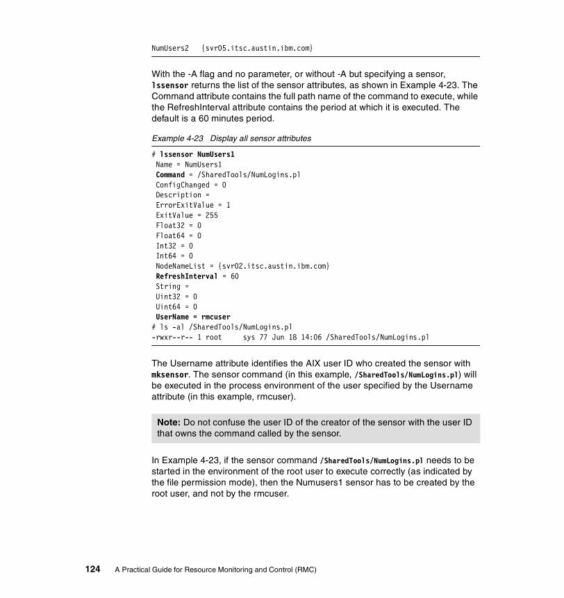
NumUsers2 {svr05.itsc.austin.ibm.com}
With the -A flag and no parameter, or without -A but specifying a sensor, lssensor returns the list of the sensor attributes, as shown in Example 4-23. The Command attribute contains the full path name of the command to execute, while the RefreshInterval attribute contains the period at which it is executed. The default is a 60 minutes period.
Example 4-23 Display all sensor attributes
# lssensor NumUsers1 Name = NumUsers1 Command = /SharedTools/NumLogins.pl ConfigChanged = 0 Description = ErrorExitValue = 1 ExitValue = 255 Float32 = 0 Float64 = 0 Int32 = 0 Int64 = 0 NodeNameList = {svr02.itsc.austin.ibm.com} RefreshInterval = 60 String = Uint32 = 0 Uint64 = 0 UserName = rmcuser# ls -al /SharedTools/NumLogins.pl-rwxr--r-- 1 root sys 77 Jun 18 14:06 /SharedTools/NumLogins.pl
The Username attribute identifies the AIX user ID who created the sensor with mksensor. The sensor command (in this example, /SharedTools/NumLogins.pl) will be executed in the process environment of the user specified by the Username attribute (in this example, rmcuser).
In Example 4-23, if the sensor command /SharedTools/NumLogins.pl needs to be started in the environment of the root user to execute correctly (as indicated by the file permission mode), then the Numusers1 sensor has to be created by the root user, and not by the rmcuser.
Note: Do not confuse the user ID of the creator of the sensor with the user ID that owns the command called by the sensor.
124 A Practical Guide for Resource Monitoring and Control (RMC)

4.7.2 mksensorThe mksensor command creates a sensor on one node. You cannot create the same sensor on multiple nodes at the same time.
By default, the sensor is created on the node specified by CT_CONTACT, but this can be overridden with the -n flag, as shown in Example 4-24, where the NumUsers1 sensor is started on node svr05 from the node svr02.
Example 4-24 Creating a sensor on a remote node
# hostnamesvr02.itsc.austin.ibm.com# echo $CT_CONTACTsvr02# lssensor -n svr05# mksensor -n svr05 NumUsers1 "/SharedTools/NumLogins.ksh"# lssensor -n svr05NumUsers1 {svr05.itsc.austin.ibm.com}
The only option that can be set during the creation of the sensor is the period at which the sensor is executed, using the -i flag followed by an integer representing a time in seconds. Apart from the sensor name, you must specify as the second argument of the mksensor command the name of the program you want to execute. You can also specify arguments to this program by surrounding the program name and its arguments with double quotes. For example, you can define the NumUsers1 sensor to run the /SharedTools/NumLogins.pl program every five minutes and pass it the abc argument with the following command:
# mksensor -i 300 NumUsers1 "/SharedTools/NumLogins.pl abc"
4.7.3 chsensorThe chsensor command is used to rename a sensor. You cannot use it to modify the sensor period or the command to be executed. If you need such a change, the only solution is to delete the sensor and recreate it.
Using the -a flag, you can rename a sensor on all nodes in the cluster, or you can restrict the renaming to a set of nodes with the -n flag, followed by the nodes names.
4.7.4 rmsensorThe rmsensor command delete sensor on one or several nodes at the same time, using the same -a and -n flags as chsensor. You can delete several sensors in one command by passing several sensor names as arguments to rmsensor.
Chapter 4. RMC command line interface 125
4.8 ERRM commandsThe Event Response resource manager handles three types of objects: conditions, responses and associations, as described in Section 2.3.1, “Event Response resource manager (ERRM)” on page 24. It provides you with five groups of commands to act on these objects. Once you know that condresp refers to an association, it becomes obvious from the names of the commands to guess their functions:
Display lscondition, lsresponse, and lscondresp
Creation mkcondition, mkresponse, and mkcondresp
Modification chcondition and chresponse
Removal rmcondition, rmresponse, and rmcondresp
Activation startcondresp and stopcondresp
The monitoring of events using the CLI follows the same principles as when using the GUI:
1. First, define the kind of event you want to monitor.
– If you are lucky, it corresponds to one of the predefined conditions that are shipped with RSCT, and you can just use it or you can create a slightly different one by copying the predefined condition and changing a few settings.
– If no predefined condition is close to your needs, there may be resources and attributes in the RMC resource managers that are what you want to monitor. In this case, you have to make your own condition. The lsrsrcdef -ad helps you find which are the dynamic attributes of resources that can be monitored.
– In the last case, you first have to define a sensor, and the condition that monitors this sensor.
2. Define the response you want the system to exercise when the events occurs. It is made from either the predefined actions or any actions you provide (programs and scripts).
3. Define associations between the conditions you want to monitor and the responses you have chosen.
4. Activate the monitoring of the actions by starting the associations.
Note: There is no concept of active or inactive sensor like there is a concept of active domain. A sensor is active as soon as defined, and you must delete it to deactivate it.
126 A Practical Guide for Resource Monitoring and Control (RMC)

Whenever you no longer want to monitor the condition, you can either stop the association if you want to reuse it later, or remove it if you definitely no longer need it.
These steps are a very simplistic view of the event monitoring feature of RMC. The ERRM commands have a rich set of options. In the following sections, we detail some of these options and explain how they can be used in concrete examples.
4.8.1 Location conceptsIn a cluster environment, there are many location concepts that must not be confused:
� The node from where you activate the monitoring of event: this is the node where the actions are executed.
� The node where the conditions and responses are defined. This is specified in the -p flag of the creation commands. To establish an association between a condition and a response, they must be defined on the same node.
� The node(s) in which events are monitored is specified with the -m and -n options of the creation commands
� The node in which is executing the RMC daemon with which commands establish a connection defined by the CT_CONTACT variable.
� The nodes in which resources will be evaluated against the command, defined by the CT_MANAGEMENT_SCOPE variable.
For example, it is possible to execute a command on node A to ask the RMC daemon on node B to activate an association of condition/responses on node C, to monitor events occurring on node A, C, and D.
The examples in the following sections detail all these geographical concepts.
4.8.2 lsconditionThe lscondition command can be used to list existing conditions, for example, when you define your event monitoring configuration and search for already available conditions. When you know condition names and pass them as command arguments, lscondition reports the status of these conditions.
Definition locationIn Example 4-25 on page 128, we look for conditions that are active, using the -m flag, which filters only the monitored conditions. All commands are executed on srv04, as demonstrated by the result of the hostname command. Since
Chapter 4. RMC command line interface 127
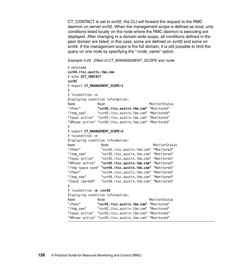
CT_CONTACT is set to svr02, the CLI will forward the request to the RMC daemon on server svr02. When the management scope is defined as local, only conditions listed locally on the node where the RMC daemon is executing are displayed. After changing to a domain wide scope, all conditions defined in the peer domain are listed; in this case, some are defined on svr02 and some on svr04. If the management scope is the full domain, it is still possible to limit the query on one node by specifying the “:node_name” option.
Example 4-25 Effect of CT_MANAGEMENT_SCOPE and :node
# hostnamesvr04.itsc.austin.ibm.com# echo $CT_CONTACTsvr02# export CT_MANAGEMENT_SCOPE=1## lscondition -mDisplaying condition information:Name Node MonitorStatus"/Peer" "svr02.itsc.austin.ibm.com" "Monitored""/tmp_new" "svr02.itsc.austin.ibm.com" "Monitored""Topas active" "svr02.itsc.austin.ibm.com" "Monitored""VMtune active" "svr02.itsc.austin.ibm.com" "Monitored"## export CT_MANAGEMENT_SCOPE=2# lscondition -mDisplaying condition information:Name Node MonitorStatus"/Peer" "svr02.itsc.austin.ibm.com" "Monitored""/tmp_new" "svr02.itsc.austin.ibm.com" "Monitored""Topas active" "svr02.itsc.austin.ibm.com" "Monitored""VMtune active" "svr02.itsc.austin.ibm.com" "Monitored""/tmp space used" "svr04.itsc.austin.ibm.com" "Monitored""/Peer" "svr04.itsc.austin.ibm.com" "Monitored""/tmp_new" "svr04.itsc.austin.ibm.com" "Monitored""Check /work04" "svr04.itsc.austin.ibm.com" "Monitored"## lscondition -m :svr02Displaying condition information:Name Node MonitorStatus"/Peer" "svr02.itsc.austin.ibm.com" "Monitored""/tmp_new" "svr02.itsc.austin.ibm.com" "Monitored""Topas active" "svr02.itsc.austin.ibm.com" "Monitored""VMtune active" "svr02.itsc.austin.ibm.com" "Monitored"
128 A Practical Guide for Resource Monitoring and Control (RMC)
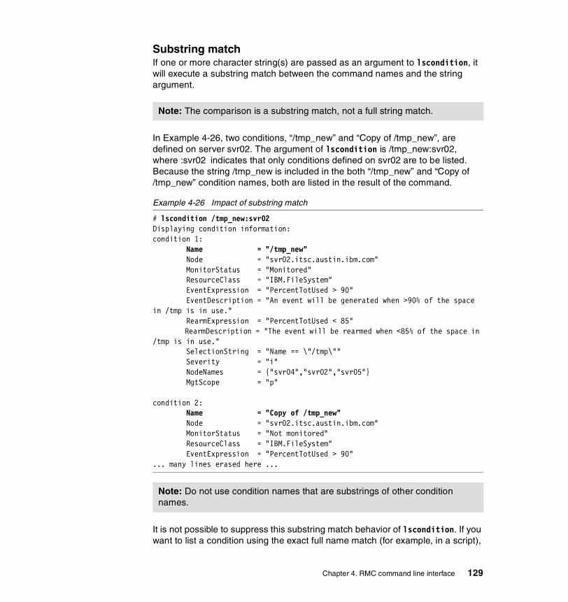
Substring matchIf one or more character string(s) are passed as an argument to lscondition, it will execute a substring match between the command names and the string argument.
In Example 4-26, two conditions, “/tmp_new” and “Copy of /tmp_new”, are defined on server svr02. The argument of lscondition is /tmp_new:svr02, where :svr02 indicates that only conditions defined on svr02 are to be listed. Because the string /tmp_new is included in the both “/tmp_new” and “Copy of /tmp_new” condition names, both are listed in the result of the command.
Example 4-26 Impact of substring match
# lscondition /tmp_new:svr02Displaying condition information:condition 1: Name = "/tmp_new" Node = "svr02.itsc.austin.ibm.com" MonitorStatus = "Monitored" ResourceClass = "IBM.FileSystem" EventExpression = "PercentTotUsed > 90" EventDescription = "An event will be generated when >90% of the space in /tmp is in use." RearmExpression = "PercentTotUsed < 85" RearmDescription = "The event will be rearmed when <85% of the space in /tmp is in use." SelectionString = "Name == \"/tmp\"" Severity = "i" NodeNames = {"svr04","svr02","svr05"} MgtScope = "p"
condition 2: Name = "Copy of /tmp_new" Node = "svr02.itsc.austin.ibm.com" MonitorStatus = "Not monitored" ResourceClass = "IBM.FileSystem" EventExpression = "PercentTotUsed > 90"... many lines erased here ...
It is not possible to suppress this substring match behavior of lscondition. If you want to list a condition using the exact full name match (for example, in a script),
Note: The comparison is a substring match, not a full string match.
Note: Do not use condition names that are substrings of other condition names.
Chapter 4. RMC command line interface 129

you can work around this behavior using the lsrsrc command rather than lscondition. However, be aware that the result has slightly different formatting, as shown in Example 4-27 (compare the attribute values such as Severity, ManagementScope and MgtScope, and so on).
Example 4-27 lsrsrc versus lscondition
# lsrsrc -s 'Name =? "/tmp_new"' IBM.ConditionResource Persistent Attributes for: IBM.Conditionresource 1: Name = "/tmp_new" ResourceClass = "IBM.FileSystem" DynamicAttribute = "PercentTotUsed" EventExpression = "PercentTotUsed > 90" EventDescription = "An event will be generated when >90% of the space in /tmp is in use." RearmExpression = "PercentTotUsed < 85" RearmDescription = "The event will be rearmed when <85% of the space in /tmp is in use." SelectionString = 'Name == "/tmp"' ImmediateEvaluate = 0 Severity = 0 NodeNames = {"svr04","svr02","svr05"} ManagementScope = 2 NodeNameList = {"svr02.itsc.austin.ibm.com"}# lscondition /tmp_new:svr02Displaying condition information:
condition 1: Name = "/tmp_new" Node = "svr02.itsc.austin.ibm.com" MonitorStatus = "Not monitored" ResourceClass = "IBM.FileSystem" EventExpression = "PercentTotUsed > 90" EventDescription = "An event will be generated when >90% of the space in /tmp is in use." RearmExpression = "PercentTotUsed < 85" RearmDescription = "The event will be rearmed when <85% of the space in /tmp is in use." SelectionString = "Name == \"/tmp\"" Severity = "i" NodeNames = {"svr04","svr02","svr05"} MgtScope = "p"
condition 2: Name = "Copy of /tmp_new" Node = "svr02.itsc.austin.ibm.com"... many lines erased here ...
130 A Practical Guide for Resource Monitoring and Control (RMC)

Details of lscondition resultExample 4-28 shows the details of the attributes of two conditions defined in our test environment. Both conditions monitor the execution of a program: vmstat or topas. The Node attribute indicates that both conditions are defined on svr02 in the cluster. The MonitorStatus attribute shows that vmstat monitoring is not activated while topas is monitored. The MgtScope attribute describes where the events are monitored. This example takes place in a peer domain cluster, and the “p” value for vmstat shows that the response is to be executed if the condition is satisfied on any node of the cluster. For topas, the NodeNames attributes restrict the monitoring to only the svr02 and svr04 nodes within the cluster.
Example 4-28 Conditions attributes
# lscondition "vmstat active"Displaying condition information:
condition 1: Name = "vmstat active" Node = "svr02.itsc.austin.ibm.com" MonitorStatus = "Not monitored" ResourceClass = "IBM.Program" EventExpression = "Processes.CurPidCount >= 1" EventDescription = "" RearmExpression = "Processes.CurPidCount = 0" RearmDescription = "" SelectionString = "ProgramName == \"vmstat\"" Severity = "i" NodeNames = {} MgtScope = "p"# lscondition "Topas active"Displaying condition information:
condition 1: Name = "Topas active" Node = "svr02.itsc.austin.ibm.com" MonitorStatus = "Monitored" ResourceClass = "IBM.Program" EventExpression = "Processes.CurPidCount >= 1" EventDescription = "" RearmExpression = "Processes.CurPidCount = 0" RearmDescription = "" SelectionString = "ProgramName == \"topas\"" Severity = "i" NodeNames = {"svr02.itsc.austin.ibm.com","svr04.itsc.austin.ibm.com"} MgtScope = "p"
Chapter 4. RMC command line interface 131

Using lscondition to create new conditionsCreating a condition manually, by typing all its flags and arguments, may result in a very long command, and it is prone to error. If an existing condition in your environment is similar to the condition you want to create, the -C option of lscondition can help you: applied to an existing condition (or several ones), it generates the command (mkcondition) that would create the same condition.
In Example 4-29, the output of lscondition -C is redirected to a temporary file. This file contains the mkcondition command necessary to create the “vmstat active” condition. For example, you only need to edit the file, replacing the \”vmstat\” string with \”smitty\”, and changing the condition name “vmstat active” to “smitty monitor” to create a condition to monitor the use of smitty on the same set of nodes in your cluster.
Example 4-29 Generating a condition creation file
# lscondition -C "vmstat active" > /tmp/mk_vmstat_condition# cat /tmp/mk_vmstat_conditionSample mkcondition command for condition "vmstat active":mkcondition -r "IBM.Program" -e "Processes.CurPidCount >= 1" -E "Processes.CurPidCount = 0" -d "Generate an event when one vmstat process is created" -D "Generate an event when no vmstat process are active" -s "ProgramName == \"vmstat\"" -S "i" -m "p" "vmstat active"
4.8.3 lsresponseThe lsresponse command is the counterpart for responses of lscondition. It has two functions:
� List responses defined in the cluster or on some of its nodes.
� Display details about the responses passed as arguments.
The lsresponse command presents similarities with lscondition:
Definition location A response is defined on one node of a cluster.
Substring match When a character string is passed as argument, it will be compared to the name of all existing responses for a substring match, so that all responses whose name contain this substring will be listed.
-C option This option will yield the mkresponse commands that could be used to create the same response and each of its actions.
132 A Practical Guide for Resource Monitoring and Control (RMC)

Details of lsresponse resultA response can be seen as a wrapper around several actions that should be performed when an event occurs. The output of lsresponse is therefore a series of paragraphs, each of which relates to one of the actions. In Example 4-30, the “Broadcast event all time” response is defined on server svr02, and consists of two actions: “BroadMsg” and “TouchLog”.
The DaysOfWeek and TimeOfDay attributes define the time frame in which the actions can be executed. In this case, it is the same time frame (at all time, and on each day of the week) for both actions, and if an event occurs within this time frame, both actions are executed.
The action script contains the absolute path of the command to execute (see the ActionScript field). The “BroadMsg” action uses one of the predefined actions, while the “TouchLog” action refers to the customer defined script /SharedTools/WhereamI19.
Example 4-30 Sample response containing two actions
# lsresponse "Broadcast event all time":svr02Displaying response information:
ResponseName = "Broadcast event all time" Node = "svr02.itsc.austin.ibm.com" Action = "BroadMsg" DaysOfWeek = 1-7 TimeOfDay = 0000-2400 ActionScript = "/usr/sbin/rsct/bin/wallevent" ReturnCode = 0 CheckReturnCode = "n" EventType = "a" StandardOut = "n" EnvironmentVars = "" UndefRes = "n"
ResponseName = "Broadcast event all time" Node = "svr02.itsc.austin.ibm.com" Action = "TouchLog" DaysOfWeek = 1-7 TimeOfDay = 0000-2400 ActionScript = "/SharedTools/WhereamI" ReturnCode = 1 CheckReturnCode = "y" EventType = "b" StandardOut = "n" EnvironmentVars = ""
19 This script is stored in the shared NFS file system in our test environment.
Chapter 4. RMC command line interface 133

UndefRes = "n"
The EventType indicates whether this action is to be triggered by the condition event, rearm event, or both. In this example, “BroadMsg” is executed when the event occurs only, while “TouchLog” is triggered by both the event and the rearm events of the condition that is associated with the response.
Response actions are executed in the background by daemons, and hence have no results directly visible by the system administrator who activates them. By default, an entry is appended to the audit log (see Section 4.9, “Audit Log commands” on page 142) for each triggered action, indicating the return code of the action. By setting ReturnCode and CheckReturnCode, you can ask for the audit log to contain extra information. The return code of the action is checked against ReturnCode and a message in the log indicates whether it is the expected result. The highlighted text in Example 4-31 shows difference between the log entries for two actions, one with the attribute ReturnCode set to “y” and the other with the attribute set to “n”.
Example 4-31 Difference in audit log entries, with and without setting ReturnCode
06/11/02 11:47:14 ERRM Error Event from VMtune active that occurred at 06/11/02 11:14:09 783476 caused /SharedTools/WhereamI from Broadcast event all time to complete with a return code of 0 which does not match with the expected return code 1.06/11/02 11:47:14 ERRM Info Event from VMtune active that occurred at 06/11/02 11:14:09 783476 caused /usr/sbin/rsct/bin/wallevent from Broadcast event all time to complete with a return code of 0.
The StandardOut element of an action is useful when debugging new actions. When set to “y”, the standard output of the action is redirected to the audit log. The standard error from an action is always redirected to the AuditLog without any configuration.
4.8.4 lscondrespThe lscondresp command is provided in order to display associations of conditions and responses, and has the same display functions as lscondition or lsreponse for conditions and responses. It has two functions:
� List associations defined in the cluster or on some of its nodes, when it is called without arguments.
� Display details about the associations as specified command line arguments.
As for the other Event Response resource manager display commands, lscondresp uses substring patterns matching when comparing its arguments with conditions or response names. By default, the argument character string is
134 A Practical Guide for Resource Monitoring and Control (RMC)

compared with the names of existing conditions. With the -r flags, the arguments are compared with response names.
In Example 4-32, we use the -a flag to restrict the display to active associations (these currently monitored). The first command lists the only defined association containing the string Topas in the condition name. The second commands, using the -r flag, returns the description of the two associations that contains the string “time” in the name of the response. In this example, two conditions, “Topas active” and “VMtune active”, are associated with the same “Broadcast event all time” response.
Example 4-32 Search by condition or response names
# lscondresp -a TopasDisplaying condition with response information:
condition-response link 1: Condition = "Topas active" Response = "Broadcast event all time" Node = "svr02.itsc.austin.ibm.com" State = "Active"# lscondresp -a -r timeDisplaying condition with response information:
condition-response link 1: Condition = "Topas active" Response = "Broadcast event all time" Node = "svr02.itsc.austin.ibm.com" State = "Active"
condition-response link 2: Condition = "VMtune active" Response = "Broadcast event all time" Node = "svr02.itsc.austin.ibm.com" State = "Active"
4.8.5 mkconditionThere are two ways to define new conditions with mkcondition:
From scratch You then have to specify all attributes of the condition, such as the node on which it will be defined, the event and optional rearm event to monitor, the domain to which the condition applies, and so on.
By copy You specify the -c flag, followed by the name of an existing condition, and you only need to provide the attributes you want to be different from the original condition. It is possible to copy
Chapter 4. RMC command line interface 135
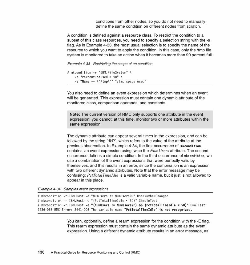
conditions from other nodes, so you do not need to manually define the same condition on different nodes from scratch.
A condition is defined against a resource class. To restrict the condition to a subset of this class resources, you need to specify a selection string with the -s flag. As in Example 4-33, the most usual selection is to specify the name of the resource to which you want to apply the condition; in this case, only the /tmp file system is monitored to take an action when it becomes more than 90 percent full.
Example 4-33 Restricting the scope of an condition
# mkcondition -r "IBM.FileSystem" \-e "PercentTotUsed > 90" \-s "Name == \"/tmp\"" "/tmp space used"
You also need to define an event expression which determines when an event will be generated. This expression must contain one dynamic attribute of the monitored class, comparison operands, and constants.
The dynamic attribute can appear several times in the expression, and can be followed by the string “@P”, which refers to the value of the attribute at the previous observation. In Example 4-34, the first occurrence of mkcondition contains an event expression using twice the NumUsers attribute. The second occurrence defines a simple condition. In the third occurrence of mkcondition, we use a combination of the event expressions that were perfectly valid by themselves, and this results in an error, since the combination is an expression with two different dynamic attributes. Note that the error message may be confusing; PctTotalTimeIdle is a valid variable name, but it just is not allowed to appear in this place.
Example 4-34 Samples event expressions
# mkcondition -r IBM.Host -e "NumUsers != NumUsers@P" UserNumberChanged# mkcondition -r IBM.Host -e "(PctTotalTimeIdle < 50)" SimpleTest# mkcondition -r IBM.Host -e "(NumUsers != NumUsers@P) && (PctTotalTimeIdle < 50)" DualTest2636-063 RMC Error: 2641-005 The variable name "PctTotalTimeIdle" is not recognized.
You can, optionally, define a rearm expression for the condition with the -E flag. This rearm expression must contain the same dynamic attribute as the event expression. Using a different dynamic attribute results in an error message, as
Note: The current version of RMC only supports one attribute in the event expression; you cannot, at this time, monitor two or more attributes within the same expression.
136 A Practical Guide for Resource Monitoring and Control (RMC)

shown in Example 4-35, where the first command is correct while the second is invalid.
Example 4-35 Attributes used in event and rearm expressions
# mkcondition -r IBM.Host -e "NumUsers >= 10" -E "NumUsers < 10" TooManyUsers# mkcondition -r IBM.Host -e "(NumUsers >= 10)" -E "(PctTotalTimeIdle < 50)" DualTest2636-063 RMC Error: 2610-341 An expression and its associated re-arm expression specify different dynamic attribute names: NumUsers and PctTotalTimeIdle.
4.8.6 mkresponseOnce you have defined a condition to monitor, you have to chose the response that will be executed when the condition is satisfied. RMC comes with seven predefined responses, which call three predefined scripts. If none of the predefined response matches your needs, you need to create one using mkresponse. As with mkcondition, you can either create it from scratch or copy an existing condition (with the -c flag). However, when copying, you cannot pass modified parameters. You must later use chresponse to modify the copied response.
A response consists of one or several actions. mkresponse only supports the specification of one action. To define a response with several actions, you use mkresponse for the creation of the response and its first action, and you then add the other actions, one at a time, with chresponse.
Please refer to Section 4.8.3, “lsresponse” on page 132, which already presented the various parameters that can be specified to mkresponse.
The -s flag specifies the full path name of the program that will be executed, either when the event expression or the rearm expression of the associated condition is triggered. This program can be a binary executable file, or a script file.
If you write your own script, you may find it useful to read the logevent, notifyevent, and wallevent scripts, which are located in /usr/sbin/rsct/bin.
It is executed in the process environment of the root user. If this environment is not sufficient to execute the command, you can specify the -E flag followed by several variable settings, such as PATH.
Chapter 4. RMC command line interface 137

In addition to the user defined environment variables, a few others are set by RMC before the action is executed. The name of all these variables starts with ERRM_.
Example 4-36 shows how a user defined script can take advantage of these variables. The “Broadcast event all time” response contain the /SharedTools/ShowEnvironment user-defined action. This action is a simple script that writes to a file, /tmp/RMC_Variables.out, the values of some RMC defined environment variables. If the expression “NumUsers != NumUsers@P” is evaluated as true on svr02, then it triggers the defined action on svr02.
Example 4-36 Using RMC defined variable in a user defined action
# lsresponse "Broadcast event all time":svr02Displaying response information:ResponseName = "Broadcast event all time" Node = "svr02.itsc.austin.ibm.com" Action = "ListVariable" DaysOfWeek = 1-7 TimeOfDay = 0000-2400 ActionScript = "/SharedTools/ShowEnvironment" ReturnCode = 0 CheckReturnCode = "n" EventType = "b" StandardOut = "n" EnvironmentVars = "" UndefRes = "n"# hostnamesvr02.itsc.austin.ibm.com# cat /SharedTools/ShowEnvironment#!/bin/kshecho "ERRM_EXP: "$ERRM_EXPR > /tmp/RMC_Variables.outecho "ERRM_NODE_NAME: " $ERRM_NODE_NAME >> /tmp/RMC_Variables.outecho "ERRM_RSRC_CLASS_PNAME: "$ERRM_RSRC_CLASS_PNAME >> /tmp/RMC_Variables.outecho "ERRM_RSRC_NAME: "$ERRM_RSRC_NAME >> /tmp/RMC_Variables.outecho "ERRM_VALUE: "$ERRM_VALUE >> /tmp/RMC_Variables.out
Note: If you monitor a sensor, please note that the sensor command is executed in the environment of the user ID who created the sensor, while the response is executed in the root user environment. Refer to Section 4.7.1, “lssensor” on page 123 for explanation of the process environment of the sensor command execution.
138 A Practical Guide for Resource Monitoring and Control (RMC)
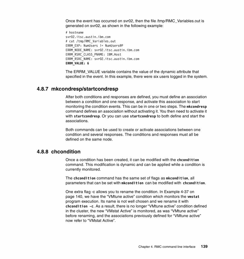
Once the event has occurred on svr02, then the file /tmp/RMC_Variables.out is generated on svr02, as shown in the following example:
# hostnamesvr02.itsc.austin.ibm.com# cat /tmp/RMC_Variables.outERRM_EXP: NumUsers != NumUsers@PERRM_NODE_NAME: svr02.itsc.austin.ibm.comERRM_RSRC_CLASS_PNAME: IBM.HostERRM_RSRC_NAME: svr02.itsc.austin.ibm.comERRM_VALUE: 6
The ERRM_VALUE variable contains the value of the dynamic attribute that specified in the event. In this example, there were six users logged in the system.
4.8.7 mkcondresp/startcondrespAfter both conditions and responses are defined, you must define an association between a condition and one response, and activate this association to start monitoring the condition events. This can be in one or two steps. The mkcondresp command defines an association without activating it. You then need to activate it with startcondresp. Or you can use startcondresp to both define and start the associations.
Both commands can be used to create or activate associations between one condition and several responses. The conditions and responses must all be defined on the same node.
4.8.8 chconditionOnce a condition has been created, it can be modified with the chcondition command. This modification is dynamic and can be applied while a condition is currently monitored.
The chcondition command has the same set of flags as mkcondition, all parameters that can be set with mkcondition can be modified with chcondition.
One extra flag -c allows you to rename the condition. In Example 4-37 on page 140, we have the “VMtune active” condition which monitors the vmstat program execution. Its name is not well chosen and we rename it with chcondition -c. As a result, there is no longer “VMtune active” condition defined in the cluster, the new “VMstat Active” is monitored, as was “VMtune active” before renaming, and the associations previously defined for “VMtune active” now refer to “VMstat Active”.
Chapter 4. RMC command line interface 139
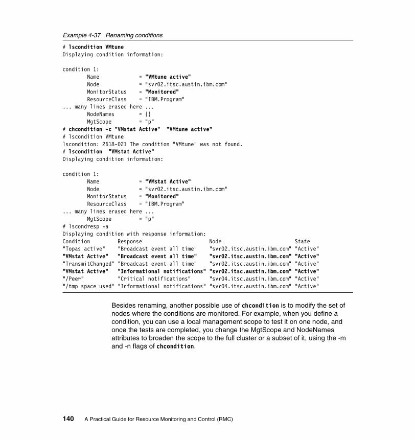
Example 4-37 Renaming conditions
# lscondition VMtuneDisplaying condition information:
condition 1: Name = "VMtune active" Node = "svr02.itsc.austin.ibm.com" MonitorStatus = "Monitored" ResourceClass = "IBM.Program"... many lines erased here ... NodeNames = {} MgtScope = "p"# chcondition -c "VMstat Active" "VMtune active"# lscondition VMtunelscondition: 2618-021 The condition "VMtune" was not found.# lscondition "VMstat Active"Displaying condition information:
condition 1: Name = "VMstat Active" Node = "svr02.itsc.austin.ibm.com" MonitorStatus = "Monitored" ResourceClass = "IBM.Program"... many lines erased here ... MgtScope = "p"# lscondresp -aDisplaying condition with response information:Condition Response Node State"Topas active" "Broadcast event all time" "svr02.itsc.austin.ibm.com" "Active""VMstat Active" "Broadcast event all time" "svr02.itsc.austin.ibm.com" "Active""TransmitChanged" "Broadcast event all time" "svr02.itsc.austin.ibm.com" "Active""VMstat Active" "Informational notifications" "svr02.itsc.austin.ibm.com" "Active""/Peer" "Critical notifications" "svr04.itsc.austin.ibm.com" "Active""/tmp space used" "Informational notifications" "svr04.itsc.austin.ibm.com" "Active"
Besides renaming, another possible use of chcondition is to modify the set of nodes where the conditions are monitored. For example, when you define a condition, you can use a local management scope to test it on one node, and once the tests are completed, you change the MgtScope and NodeNames attributes to broaden the scope to the full cluster or a subset of it, using the -m and -n flags of chcondition.
140 A Practical Guide for Resource Monitoring and Control (RMC)

4.8.9 chresponseA response consists of several possible actions, and mkresponse only defines, at most, one action. To add or delete actions in a response, use chresponse with the -a or -p flags, respectively.
When adding an action, you can define the same attributes as when creating the initial action, using the same flags as those of mkresponse for chresponse, except -p. This flag, for mkresponse, is used to specify the target node where an response is defined, while it specifies deleting an action for chresponse.
You can also rename a response with chresponse -c.
Like chcondition, chresponse is dynamic and can be applied to responses used in active associations.
It is currently not possible to modify an action within a response. For example, if you have defined an action to be valid from 8 a.m. to 6 p.m., Monday to Friday, and you now want to change this time period, you need to delete the action from the response with chresponse -p, and recreate it with chresponse -a and the new time frame values.
4.8.10 stopcondresp/rmcondrespOnce you now longer need the system to react to a condition event, you use stopcondresp to deactivate the association. This leaves the association defined on the system for future use. If you do not expect to reuse it, you can, at the same time, stop monitoring and delete the association with rmcondresp.
You can stop monitoring several associations with one command, but they must all relate to the same condition.
4.8.11 rmcondition/rmresponseWhen condition and response are no longer needed, you can delete them respectively with rmcondition and rmresponse. If applied to conditions or responses used in active associations, the commands will return an error unless you specify the -f flag.
Example 4-38 Forcing deletion of a monitored condition
# rmcondition "VMstat active"rmcondition: 2618-062 The condition "VMstat active" is linked to one or more responses and cannot be removed.# rmcondition -f "VMstat active"
Chapter 4. RMC command line interface 141
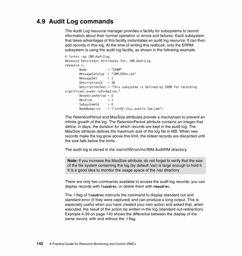
4.9 Audit Log commandsThe Audit Log resource manager provides a facility for subsystems to record information about their normal operation or errors and failures. Each subsystem that takes advantages of this facility instantiates an audit log resource. It can then add records in this log. At the time of writing this redbook, only the ERRM subsystem is using the audit log facility, as shown in the following example:
# lsrsrc -ap IBM.AuditLogResource Persistent Attributes for: IBM.AuditLogresource 1: Name = "ERRM" MessageCatalog = "IBM.ERrm.cat" MessageSet = 1 DescriptionId = 38 DescriptionText = "This subsystem is defined by ERRM for recording significant event information." RetentionPeriod = 0 MaxSize = 1 SubsystemId = 0 NodeNameList = {"svr02.itsc.austin.ibm.com"}
The RetentionPeriod and MaxSize attributes provide a mechanism to prevent an infinite growth of the log. The RetentionPeriod attribute contains an integer that define, in days, the duration for which records are kept in the audit log. The MaxSize attribute defines the maximum size of the log file in MB. When new records make the log grow above this limit, the oldest records are discarded until the size falls below the limits.
The audit log is stored in the /var/ct/IW/run/mc/IBM.AuditRM directory.
There are only two commands available to access the audit log records: you can display records with lsaudrec, or delete them with rmaudrec.
The -l flag of lsaudrec instructs the command to display standard out and standard error (if they were captured) and can produce a long output. This is especially useful when you have created your own action and asked that, when executed, the result of the action be written in the log (standard out redirection). Example 4-39 on page 143 shows the difference between the display of the same record, with and without the -l flag.
Note: If you increase the MaxSize attribute, do not forget to verify that the size of the file system containing the log (by default /var) is large enough to hold it. It is a good idea to monitor the usage space of the /var directory
142 A Practical Guide for Resource Monitoring and Control (RMC)

Example 4-39 Impact of -l flag
# lsaudrec -l -s "Time > #-000001"Time = 06/13/02 15:18:35 775848Subsystem = ERRMCategory = ErrorDescription = Event from VMstat Active that occurred at 06/13/02 15:18:34 955814 caused /SharedTools/WhereamI from Broadcast Event All Time to complete with a return code of 0 which does not match with the expected return code 1.Standard Output = svr02.itsc.austin.ibm.com hello world
# lsaudrec -s "Time > #-000001"Time Subsystem Category Description006/13/02 15:18:35 ERRM Info Event from VMstat Active that occurred at 06/13/02 15:18:34 955814 caused /SharedTools/ShowEnvironment from Broadcast Event All Time to complete with a return code of 0.
Because the audit log is most likely to contain a very large number of records, both lsaudrec and rmaudrec support a selection mechanism to filter a subset of these records. The easiest selection is based on the time of creation of the record. For example, you can select all records created on June 13th, between 15:18 and 15:19, using the following command:
# lsaudrec -s "Time > #06131518 && Time < #06131519"
4.10 Additional security configurationThe security concept of RMC consists of two different parts: authentication and authorization. Authentication is the process of ensuring that the client of RMC is really who she/he is claiming to be. Once the client is authenticated, authorization is the process that verifies that this client has the right to perform the requested action.
4.10.1 AuthorizationRMC implements authorization using an Access Control List (ACL) file. Each time a client uses a command, the RMC subsystem will retrieve from this ACL file, if the user has been authorized for such an action.
RSCT Resource Monitoring and Control provides a default configuration file, /usr/sbin/rsct/cfg/ctrmc.acls. The default ACL file gives:
� Full privilege to the root user on the local system.
� Read access to all resources for other users defined locally on the same system.
Chapter 4. RMC command line interface 143

� No access to users defined on other systems.
You are likely to need a different set of authorizations in your environment, for example, to give your system administrators IDs the right to create conditions and responses, you will need to modify the ACL file. However, you must not modify /usr/sbin/rsct/cfg/ctrmc.acls. You have to copy it to /var/ct/cfg/ctrmc.acls and make your modifications in this copy. Once done, you need to have the RMC daemon reread the ACLs by refreshing the subsystem with refresh -s ctrmc.
If you are working in a cluster environment, the cluster configuration commands automatically create this copy, and customize it. In a peer domain, the default is to give root on any node of the cluster full privileges on any class and resource in the whole cluster. Configuration of a peer domain does not remove access for local users on the cluster nodes.
If you are in a peer domain cluster, and you want to grant the same authorizations on all nodes, you need to update the ACL file and refresh the RMC daemon on each node. But in this case, you do not have to manually edit the file on each node. The content of the file will be independent from any node, so you can maintain the file on one node, and copy it to all other nodes.
The format of the ACL file is detailed in Chapter 3 of the IBM RSCT for AIX: Guide and Reference, SA22-7889.
The access control granularity is on a per resource class basis. The ACL file contains one stanza for each class. Within the class, you can grant access to individual users, all users on a host, or all users on any host. The access is granted to the class itself or to all resources in the class. Access right are read (r) or write (w).
If you decide to grant privileges to a user to execute an RMC command, please refer to Chapters 9 and 10 in the IBM RSCT for AIX: Technical Reference, SA22-7890. The security section indicates which access rights for which resource class must be given.
As a general rule of thumb, a user needs read privilege to display information (with the ls… commands) and write privilege to create, modify, or delete resources (with the mk…, ch…, and rm… commands).
For the following examples, we have created an AIX user (rmcuser) on node svr01, and all commands and files are local to this node. The rmcuser user has no specific rights, and we will grant it several privileges.
First, we want to allow it to create conditions. We have modified the /var/ct/cfg/ctrmc.acls file and inserted a stanza for the IBM.Condition resource class, as shown in Example 4-40 on page 145.
144 A Practical Guide for Resource Monitoring and Control (RMC)

Example 4-40 Condition access rights
IBM.Condition rmcuser@LOCALHOST C rw rmcuser@LOCALHOST R r LOCALHOST * r * *
The last line prevents any user from another host to access the conditions. The LOCALHOST statement in the fourth line allows all users logged on svr01 to display information about conditions defined on svr01.
The second line containing rmcuser grants it the right to read and write the IBM.Condition class, and therefore to create new conditions, or to remove already defined conditions. The third line containing rmcuser grants it only the read right to the IBM.Condition resources, so it can list information about the existing conditions, but it prevents the user from changing an existing condition.
There is no line specific to the root user in this IBM.Condition stanza. Therefore, the root user only has the rights corresponding to the line containing LOCALHOST, which is read only.
Now that rmcuser can create conditions, we give it the right to create responses, by adding the lines listed in Example 4-41 to the ACL file.
Example 4-41 Responses access rights
IBM.EventResponse root@LOCALHOST * rw rmcuser@LOCALHOST C rw rmcuser@LOCALHOST R r LOCALHOST C r LOCALHOST R r * *
These lines give all rights to root about responses, give rights to rmcuser to create or delete responses but not to modify them, and only give to other local users, the possibility to list information about existing responses.
Note: Because the access rights are resource class-wide and there is no concept of condition ownership, if you grant a user the privilege to create conditions, the user is also able to delete any condition, including the predefined one, and the conditions defined by other users.
Note: You need the right to modify a response to add actions. The example above would prevent rmcuser from creating responses containing multiple actions.
Chapter 4. RMC command line interface 145

The rmcuser now needs to activate monitoring of the conditions he has defined. We give it the access rights to the association class by adding lines to the ACL files, as shown in Example 4-42.
Example 4-42 Association access rights
IBM.Association root@LOCALHOST * rw rmcuser@LOCALHOST * rw LOCALHOST * r * *
The rw rights to the IBM.Association class gives the right to rmcuser to create and delete associations, as well as to stop and start their monitoring activity.
In Example 4-43, we propose a more secure configuration. We assume that two users exist on the system: we give user rmcadmin all rights to create conditions, responses, and associations, while we only allow rmcuser to create conditions and associate them with responses defined by rmcadmin, in order to prevent rmcuser from writing its own programs and having the system execute them with root privileges.
Example 4-43 Configuration with two user IDs
IBM.Condition rmcadmin@LOCALHOST * rw rmcuser@LOCALHOST * rw LOCALHOST * r * *
IBM.EventResponse rmcadmin@LOCALHOST * rw LOCALHOST * r * *
IBM.Association rmcadmin@LOCALHOST * rw rmcuser@LOCALHOST * rw LOCALHOST * r * *
Important: Remember that actions defined in a response are executed in the process environment of the root user. Therefore, any user who has the right to create a response can have the system execute, on his behalf, any command requiring AIX root privilege.
146 A Practical Guide for Resource Monitoring and Control (RMC)

4.10.2 Remote node accessYou can use RMC commands on one server to manage resources on another server by setting the CT_CONTACT variable, even if both servers are not part of a cluster or a peer domain. For example, if you have to remotely administer AIX systems from another AIX system that may be located on another site (as shown in Figure 4-4), you can use the methods20 explained in the following steps:
Figure 4-4 Remote management without a cluster configuration
1. Modify the ACL file on svr06 by adding the highlighted line to the DEFAULT stanza, as shown in the following example:
# cat /var/ct/cfg/ctrmc.aclsIBM.HostPublic * * r UNAUTHENT * r
DEFAULT root@LOCALHOST * rw [email protected] * rw LOCALHOST * r
20 You must have a reliable TCP/IP connection between the AIX system that you are currently logged into and the remotely managed systems.
Note: In the following steps, we assume that:
� The default AIX 5L Version 5.1 installation has been performed on all the servers and no RMC customization has been performed yet.
� All files are referenced by the default names and location.
� The root user on server svr05 can be allowed to execute any actions on any RMC class or resources of server svr06.
svr05
StandaloneRMC node
Remote managedserver(s)
svr06
TCP/IP network
Remote RMC command requests
Chapter 4. RMC command line interface 147

The root user on svr05 is now authorized to execute RMC commands on svr06; however, you still have to configure the authentication mechanism. If you execute some RMC commands from svr05 to svr06, you will receive an error message, as shown in the following example:
# echo $CT_CONTACTsvr06# lsrsrclsrsrc: 2612-024 Could not authenticate user.
2. Customize the authentication daemon configuration file by copying the sample file /usr/sbin/rsct/cfg/ctcasd.cfg in the /var/ct/cfg directory. You have to edit the file to set variable values, as highlighted in the following example:
# cat /var/ct/cfg/ctcasd.cfgTRACE= falseTRACEFILE=TRACELEVELS=TRACESIZE=RQUEUESIZE=MAXTHREADS=MINTHREADS=HBA_USING_SSH_KEYS= falseHBA_PRVKEYFILE=/var/ct/cfg/ct_has.pkfHBA_PUBKEYFILE=/var/ct/cfg/ct_has.qkfHBA_THLFILE=/var/ct/cfg/ct_has.thlHBA_KEYGEN_METHOD= rsa1024SERVICES=hba CAS
3. Generate the private and public key files on both nodes. These two files, ct_has.pkf and ct_has.qkf, should be located in the /var/ct/cfg directory and be consistent with the variables defined in the previous example.
To create a pair of key files, use the ctskeygen command, as shown in the following example:
# ctskeygen -n -f -m rsa1024# ls -l /var/ct/cfgct_ha*-r--r--r-- 1 root system 145 Jun 24 13:42 ct_has.pkf-r-------- 1 root system 271 Jun 24 13:42 ct_has.qkf
4. Start the authentication subsystem on both nodes.
# startsrc -s ctcas
Note: If these files already exist and are not empty, your server authentication mechanism has already been configured. Do not continue this process.
148 A Practical Guide for Resource Monitoring and Control (RMC)

5. Dump the public key into a file that will be transferred to the other server on each node. For example, issue the following command on svr06:
# ctskeygen -d ctskeygen -d > /tmp/svr06_public.sh
6. Edit the generated files to include the ctsthl command on both nodes. For example, if the /tmp/svr06_public.sh file on svr06 contains the following content:
# cat /tmp/svr06_public.sh120400c980e236ab459f7a5510180bd854a0b2eb5ace87b646b9b0165ab620f2f0b166848becc0eacfe68c5263f48d6dec34d4fd1b84c964fce1d9924a44ab689f46f7030949de4d4e7858e81456c33bd8f5f74d4492a4d12a82ee435b86d2cec9526805097d46a0bb17094318c423fb182d8e089f78d3e39efa72de4aa986f78aa8cf0103(generation method: rsa1024)
then insert the following string in the first line of the file and remove the last line:
/usr/sbin/rsct/bin/ctsthl -a -m rsa1024 -n svr06.itsc.austin.ibm.com -p
The edited file should have the following content and it must have only one line:
# cat /tmp/svr06_public.sh/usr/sbin/rsct/bin/ctsthl -a -m rsa1024 -n svr06.itsc.austin.ibm.com -p120400c980e236ab459f7a5510180bd854a0b2eb5ace87b646b9b0165ab620f2f0b166848becc0eacfe68c5263f48d6dec34d4fd1b84c964fce1d9924a44ab689f46f7030949de4d4e7858e81456c33bd8f5f74d4492a4d12a82ee435b86d2cec9526805097d46a0bb17094318c423fb182d8e089f78d3e39efa72de4aa986f78aa8cf0103
7. Transfer the created shell script containing the svr06’s public key from svr06 to svr05, and execute it on svr05. Then do the opposite operation. It will add the peer’s public key into the trusted host list on the other peer.
The following example shows how to add the svr06’s public key to the trusted host list on svr05:
# hostnamesvr05.itsc.austin.ibm.com# touch /var/ct/cfg/ct_has.thl# ksh /tmp/svr06_public.sh
Please note if the trusted host list file does not exist on one of the hosts before invoking the shell script, create an empty one using the touch command.
Note: When executed on server A, the ctsthl command should take the public key of server B as an argument and add it to the trusted host list (/var/ct/cfg/ct_has.thl) on server A.
Chapter 4. RMC command line interface 149

8. Verify the peer’s public key is correctly added to the trusted host list.
The following example shows how to verify if the svr06’s public key is correctly added on svr05:
# hostnamesvr05.itsc.austin.ibm.com# ctsthl -lctsthl: Contents of trusted host list file:--------------------Host name: svr06.itsc.austin.ibm.comIdentifier Generation Method: rsa1024Identifier Value:120400c980e236ab459f7a5510180bd854a0b2eb5ace87b646b9b0165ab620f2f0b166848becc0eacfe68c5263f48d6dec34d4fd1b84c964fce1d9924a44ab689f46f7030949de4d4e7858e81456c33bd8f5f74d4492a4d12a82ee435b86d2cec9526805097d46a0bb17094318c423fb182d8e089f78d3e39efa72de4aa986f78aa8cf0103
Now you can remotely execute commands from svr05 to svr06 or vice versa. In Example 4-44, the root user on svr05 has set the CT_CONTACT variable to svr06.itsc.austin.ibm.com and issued the lsrsrc command to get the description of the IBM.Host resource known by the Host resource manager on svr06.
Example 4-44 Remote command execution
# hostnamesvr05.itsc.austin.ibm.com# echo $CT_CONTACTsvr06.itsc.austin.ibm.com# lsrsrc "IBM.Host"Resource Persistent Attributes for: IBM.Hostresource 1: Name = "svr06.itsc.austin.ibm.com" NodeNameList = {"svr06.itsc.austin.ibm.com"} NumProcessors = 4 RealMemSize = 1073639424 OSName = "AIX" KernelVersion = "5.1" DistributionName = "IBM" DistributionVersion = "5.1" Architecture = "ppc"
150 A Practical Guide for Resource Monitoring and Control (RMC)

Chapter 5. Monitoring applications
You can exploit RMC to monitor applications such as DB2 Universal Database for AIX Version 7.2 (DB2 UDB) and IBM HTTP Server (IHS). In this chapter, we show you several examples on how to monitor these applications using RMC.
This chapter describes the following topics:
� Section 5.1, “How to monitor DB2 Universal Database” on page 152
� Section 5.2, “Advanced monitoring” on page 156
� Section 5.3, “How to send events to Tivoli Enterprise Console” on page 170
Throughout this chapter, we use the RMC command line interface instead of Web-based System Manager to define and monitor applications.
5
© Copyright IBM Corp. 2002. All rights reserved. 151

5.1 How to monitor DB2 Universal DatabaseTo keep applications running, the following system resources are generally required:
� The existence of the application processes.
� The minimum CPU resources to satisfy the required transaction performance of the application.
� Sufficient memory resources to be used by application processes, including:
– Free physical memory pages– Shared memory segments
� Sufficient file system resources to be used by application processes, including:
– Data files– Log files
In this section, we first describe several methods for monitoring DB2 UDB. We also describe how to monitor DB2 UDB using the program resource class (IBM.Program) managed by the host resource manager (see Section 2.3.5, “Host resource manager” on page 28).
As a general point of view, there are many methods for monitoring DB2 UDB, because the method you should use depends on your system and your requirements. Thus, we describe the basic methods for monitoring DB2 UDB here:
� Monitoring DB2 UDB abnormal activity
DB2 UDB provides several log files, such as db2diag.log, db2alert.log, and so on. You can detect abnormal activity by checking these log files.
� Monitoring DB2 UDB application resources
DB2 UDB provides several functions for monitoring its application resources, such as the governor, snapshot monitor, event monitor, and so on. You can set threshold values against DB2 UDB resources, such as wasted CPU time, number of locks, and so on, using the governor. You can also monitor table space usage percentage by checking DB2 UDB system tables.
� Monitoring DB2 UDB processes
In AIX, you can verify whether relevant DB2 UDB processes are running or not by using the ps command. For example, you can check if the database server is running, if a DB2 UDB application that is bound to DB2 UDB has an agent assigned to it, and so on.
152 A Practical Guide for Resource Monitoring and Control (RMC)

Although there are several ways to monitor UDB by exploiting RMC, we provide the following examples in this chapter:
� Monitoring DB2 UDB processes in Section 5.1.2, “Configure a DB2 UDB monitor resource” on page 155.
� Monitoring DB2 UDB application responses in Section 5.2.2, “Advanced monitoring example” on page 160.
For further information about the DB2 UDB administration, please refer to the IBM DB2 Universal Database Administration Guide: Performance Version 7, SC09-2945.
5.1.1 Components to be monitoredYou can easily verify if a DB2 UDB instance is running by checking the existence of the relevant DB2 UDB processes. The following list21 contains the most vital DB2 UDB processes:
db2sysc DB2 system controller process
db2gds Global daemon spawner that spawns new processes
db2ipccm Local client connection listener process
db2tcpcm TCP/IP protocol listener process
db2resyn Resync agent process that scans the global resync list
db2wdog Watchdog process that handles abnormal terminations
Once you have started DB2 UDB, you can see these processes running (see Example 5-2 on page 154). You might want to know which process should be monitored in order to monitor a DB2 UDB instance. However, just monitoring the db2sysc process is sufficient for our purposes, because DB2 UDB processes keep watching each other, so if one process should be down, all the other processes are also down. This is well-known behavior defined by the DB2 UDB architecture.
For further information about the DB2 UDB process relationship and its architecture, please refer to the IBM DB2 Universal Database Troubleshooting Guide Version 7, GC09-2850.
Example 5-1 on page 154 shows DB2 UDB processes using the -ef option of the ps command. You can easily distinguish each process name shown in the last column (CMD).
21 This is not a complete list. You may find other processes in your DB2 UDB environment.
Chapter 5. Monitoring applications 153
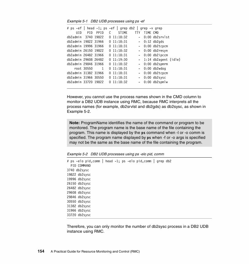
Example 5-1 DB2 UDB processes using ps -ef
# ps -ef | head -1; ps -ef | grep db2 | grep -v grep UID PID PPID C STIME TTY TIME CMDdb2admin 3740 19822 0 11:18:32 - 0:00 db2srvlstdb2admin 19822 31966 0 11:18:31 - 0:12 db2gdsdb2admin 19996 31966 0 11:18:31 - 0:00 db2tcpcmdb2admin 26150 19822 0 11:18:32 - 0:00 db2resyndb2admin 26482 31966 0 11:18:31 - 0:00 db2ipccmdb2admin 29608 26482 0 11:19:30 - 1:14 db2agent (idle)db2admin 29846 31966 0 11:18:32 - 0:00 db2spmrm root 30550 1 0 11:18:31 - 0:00 db2wdogdb2admin 31382 31966 0 11:18:31 - 0:00 db2tcpcmdb2admin 31966 30550 0 11:18:31 - 0:00 db2syscdb2admin 33720 19822 0 11:18:32 - 0:00 db2spmlw
However, you cannot use the process names shown in the CMD column to monitor a DB2 UDB instance using RMC, because RMC interprets all the process names (for example, db2srvlst and db2gds) as db2sysc, as shown in Example 5-2.
Example 5-2 DB2 UDB processes using ps -elo pid, comm
# ps -elo pid,comm | head -1; ps -elo pid,comm | grep db2 PID COMMAND3740 db2sysc19822 db2sysc19996 db2sysc26150 db2sysc26482 db2sysc29608 db2sysc29846 db2sysc30550 db2sysc31382 db2sysc31966 db2sysc33720 db2sysc
Therefore, you can only monitor the number of db2sysc process in a DB2 UDB instance using RMC.
Note: ProgramName identifies the name of the command or program to be monitored. The program name is the base name of the file containing the program. This name is displayed by the ps command when -l or -o comm is specified. The program name displayed by ps when -f or -o args is specified may not be the same as the base name of the file containing the program.
154 A Practical Guide for Resource Monitoring and Control (RMC)
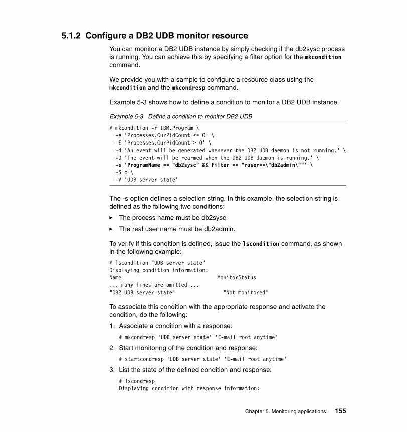
5.1.2 Configure a DB2 UDB monitor resourceYou can monitor a DB2 UDB instance by simply checking if the db2sysc process is running. You can achieve this by specifying a filter option for the mkcondition command.
We provide you with a sample to configure a resource class using the mkcondition and the mkcondresp command.
Example 5-3 shows how to define a condition to monitor a DB2 UDB instance.
Example 5-3 Define a condition to monitor DB2 UDB
# mkcondition -r IBM.Program \-e 'Processes.CurPidCount <= 0' \-E 'Processes.CurPidCount > 0' \-d 'An event will be generated whenever the DB2 UDB daemon is not running.' \-D 'The event will be rearmed when the DB2 UDB daemon is running.' \-s 'ProgramName == "db2sysc" && Filter == "ruser==\"db2admin\""' \-S c \-V 'UDB server state'
The -s option defines a selection string. In this example, the selection string is defined as the following two conditions:
� The process name must be db2sysc.
� The real user name must be db2admin.
To verify if this condition is defined, issue the lscondition command, as shown in the following example:
# lscondition "UDB server state"Displaying condition information:Name MonitorStatus... many lines are omitted ..."DB2 UDB server state" "Not monitored"
To associate this condition with the appropriate response and activate the condition, do the following:
1. Associate a condition with a response:
# mkcondresp 'UDB server state' 'E-mail root anytime'
2. Start monitoring of the condition and response:
# startcondresp 'UDB server state' 'E-mail root anytime'
3. List the state of the defined condition and response:
# lscondrespDisplaying condition with response information:
Chapter 5. Monitoring applications 155

Condition Response State"UDB server state" "E-mail root anytime" "Active"
If you start and stop this DB2 UDB instance, you will receive the event and the rearm event notification using e-mail, as shown in the following example:
From root Wed May 29 11:51:45 2002Date: Wed, 29 May 2002 11:51:45 +0900From: rootTo: rootSubject: UDB server state
=====================================
Wednesday 05/29/02 11:51:44
Condition Name: UDB server stateSeverity: CriticalData Type: EventExpression: Processes.CurPidCount <= 0
Resource Name: ProgramName == 'db2sysc' && Filter == 'ruser== db2admin'Resource Class: ProgramData Type: CT_SD_PTRData Value: [0,1,{},{26896}]Node Name: f02n13Node NameList: {f02n13}Resource Type: 0=====================================
5.2 Advanced monitoringIn this section, we explore what we can do for advanced monitoring with user defined scripts and the IBM.Sensor resource class. You can also create your own response, which calls your script using the mkresponse command. Combining these two, you can have an advanced monitoring method of your application. We explain how this method will work using several examples in this section.
5.2.1 Define your own sensorIBM.Sensor is a resource class that periodically invokes a user defined script. The result of this script can then be monitored by ERRM. You can implement your own algorithm in the script to monitor your application; however, the script has to use an appropriate format, which the sensor resource manager accepts, to return values.
156 A Practical Guide for Resource Monitoring and Control (RMC)
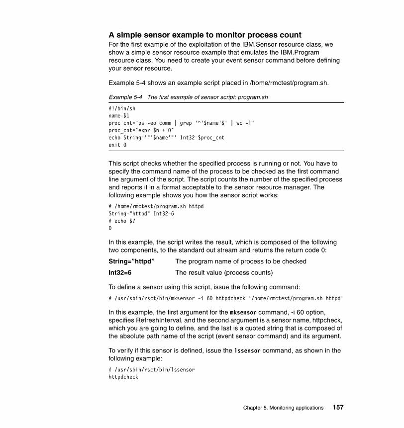
A simple sensor example to monitor process countFor the first example of the exploitation of the IBM.Sensor resource class, we show a simple sensor resource example that emulates the IBM.Program resource class. You need to create your event sensor command before defining your sensor resource.
Example 5-4 shows an example script placed in /home/rmctest/program.sh.
Example 5-4 The first example of sensor script: program.sh
#!/bin/shname=$1proc_cnt=`ps -eo comm | grep '^'$name'$' | wc -l`proc_cnt=`expr $n + 0`echo String='"'$name'"' Int32=$proc_cntexit 0
This script checks whether the specified process is running or not. You have to specify the command name of the process to be checked as the first command line argument of the script. The script counts the number of the specified process and reports it in a format acceptable to the sensor resource manager. The following example shows you how the sensor script works:
# /home/rmctest/program.sh httpdString="httpd" Int32=6# echo $?0
In this example, the script writes the result, which is composed of the following two components, to the standard out stream and returns the return code 0:
String=”httpd” The program name of process to be checked
Int32=6 The result value (process counts)
To define a sensor using this script, issue the following command:
# /usr/sbin/rsct/bin/mksensor -i 60 httpdcheck '/home/rmctest/program.sh httpd'
In this example, the first argument for the mksensor command, -i 60 option, specifies RefreshInterval, and the second argument is a sensor name, httpcheck, which you are going to define, and the last is a quoted string that is composed of the absolute path name of the script (event sensor command) and its argument.
To verify if this sensor is defined, issue the lssensor command, as shown in the following example:
# /usr/sbin/rsct/bin/lssensorhttpdcheck
Chapter 5. Monitoring applications 157
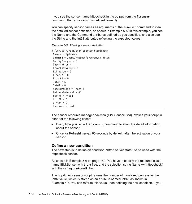
If you see the sensor name httpdcheck in the output from the lssensor command, then your sensor is defined correctly.
You can specify sensor names as arguments of the lssensor command to view the detailed sensor definition, as shown in Example 5-5. In this example, you see the Name and the Command attributes defined as you specified, and also see the String and the Int32 attributes reflecting the expected values.
Example 5-5 Viewing a sensor definition
# /usr/sbin/rsct/bin/lssensor httpdcheck Name = httpdcheck Command = /home/rmctest/program.sh httpd ConfigChanged = 0 Description = ErrorExitValue = 1 ExitValue = 0 Float32 = 0 Float64 = 0 Int32 = 6 Int64 = 0 NodeNameList = {f02n13} RefreshInterval = 60 String = httpd Uint32 = 0 Uint64 = 0 UserName = root
The sensor resource manager daemon (IBM.SensorRMd) invokes your script in either of the following cases:
� Every time you issue the lssensor command to show the detail information about the sensor.
� Once for RefreshInterval, 60 seconds by default, after the activation of your sensor.
Define a new conditionThe next step is to define an condition, “httpd server state”, to be used with the httpdcheck sensor.
As shown in Example 5-6 on page 159, You have to specify the resource class name IBM.Sensor with the -r flag, and the selection string Name == “httpdcheck” with the -s flag of mkcondition.
The httpdcheck sensor script returns the number of monitored process as the Int32 value, which is stored as an attribute named Int32, as shown in Example 5-5. You can refer to this value upon defining the new condition. If you
158 A Practical Guide for Resource Monitoring and Control (RMC)

define the event expression as Int32 <= 0, an event will be generated when the Int32 value is less than or equal to 0, which means that no process is running. The rearm expression is defined as Int32 > 0, which means that at least one process is running.
Example 5-6 Defining a new condition using a sensor
# mkcondition -r IBM.Sensor \-e 'Int32 <= 0' \-E 'Int32 > 0' \-d 'An event will be generated whenever the httpd does not run.' \-D 'The event will be rearmed when the httpd runs.' \-s 'Name == "httpdcheck"' \-S c \'httpd server state'
Associate a condition with a responseTo associate a new condition with a response, do the following steps:
1. Associate the condition “httpd server state” with the response “E-mail root anytime”:
# mkcondresp 'httpd server state' 'E-mail root anytime'
2. Start monitoring of the newly associated condition and response:
# startcondresp 'httpd server state' 'E-mail root anytime'
3. Verify the state of the condition and response:
# lscondrespDisplaying condition with response information:Condition Response State"httpd server state" "E-mail root anytime" "Active"
If you start and stop the httpd daemon, the root user will receive event and rearm event notification by e-mail, as shown in the following example:
From root Sat Jun 1 13:12:30 2002Date: Sat, 1 Jun 2002 13:12:30 +0900From: rootTo: rootSubject: httpd server state
=====================================
Saturday 06/01/02 13:12:30
Condition Name: httpd server stateSeverity: CriticalData Type: Event
Chapter 5. Monitoring applications 159

Expression: Int32 <= 0
Resource Name: httpdcheckResource Class: SensorData Type: CT_INT32Data Value: 0Node Name: f02n13Node NameList: {f02n13}Resource Type: 0=====================================
Figure 5-1 illustrates the relationships between the objects we defined in this example.
Figure 5-1 Relationship between sensor, response, and others
5.2.2 Advanced monitoring exampleThe existence of a process does not always assure that the process is working correctly. You might want to verify whether your application is working correctly by accessing the application. For example, you can verify that DB2 UDB is running correctly by issuing a simple query request.
Monitoring responses from DB2 UDBExample 5-7 shows an sample script that connects to the DB2 UDB instance db2inst1 and selects from syscat.tables, which is predefined in DB2 UDB.
Example 5-7 Monitoring DB2 UDB response: udbcheck.sh
#!/bin/shDBINSNAME=db2inst1DBNAME=db2test
Condition“httpd serverstate”
Response“E-mail root
anytime”Resource
httpdcheck
program.sh
call
associated
call
specify
Event sensor command
event
rearm event
Predefined action“E-mail root”
Predefined scriptnotifyevent
IBM.Sensor
160 A Practical Guide for Resource Monitoring and Control (RMC)
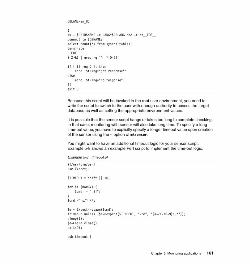
DBLANG=en_US
(su - $DBINSNAME -c LANG=$DBLANG db2 -t <<__EOF__connect to $DBNAME;select count(*) from syscat.tables;terminate;__EOF__) 2>&1 | grep -q '^ *[0-9]'
if [ $? -eq 0 ]; thenecho 'String="got response"'
elseecho 'String="no response"'
fiexit 0
Because this script will be invoked in the root user environment, you need to write the script to switch to the user with enough authority to access the target database as well as setting the appropriate environment values.
It is possible that the sensor script hangs or takes too long to complete checking. In that case, monitoring with sensor will also take long time. To specify a long time-out value, you have to explicitly specify a longer timeout value upon creation of the sensor using the -i option of mksensor.
You might want to have an additional timeout logic for your sensor script. Example 5-8 shows an example Perl script to implement the time-out logic.
Example 5-8 tImeout.pl
#!/usr/bin/perluse Expect;
$TIMEOUT = shift || 10;
for $i (@ARGV) {$cmd .= " $i";
}$cmd =~ s/^ //;
$e = Expect->spawn($cmd);&timeout unless ($e->expect($TIMEOUT, "-re", "[A-Za-z0-9]=.*"));sleep(1);$e->hard_close();exit(0);
sub timeout {
Chapter 5. Monitoring applications 161

sleep(1);print(STDOUT "String=\"timeout\"\n");$e->hard_close();exit(0);
}
You can test this Perl script before using it in a sensor, as shown in the following example:
# timeout.pl 10 udbcheck.sh
The first argument for timeout.pl is a timeout value in seconds, and the rest of arguments is the sensor event command (and possibly its arguments). The timeout.pl script executes the specified command and reads from the standard output of the command, waiting up to the specified timeout value. If the script reads a line from the command’s standard output, it simply echoes the received line to its standard output. If the script gets timed-out, it writes the timeout message.
We used an Perl module, named Expect.pm, which emulates the Expect language (hereafter referred to as Expect/Perl). The following line in Example 5-8 on page 161 declares that the script is importing symbols provided by Expect/Perl:
use Expect;
Installing Perl/Expect is an easy task, because Perl22 is installed by default on AIX 5L Version 5.1. You only have to download and install several modules required for Perl/Expect (Appendix B, “Useful information” on page 179 shows how to install Perl/Expect). For further information about Perl/Expect, refer to Managing AIX Server Farms, SG24-6606.
Example 5-9 shows the following steps:
1. Define a new sensor resource (udbcheck).
2. Define a new condition (udbcheck).
3. Associate the condition udbcheck and the response “E-mail root anytime”.
4. Start this condition and response.
Example 5-9 Activate sensor with udbcheck.sh
# /usr/sbin/rsct/bin/mksensor udbcheck /home/rmctest/timeout.pl 10 \/home/rmctest/udbcheck.sh
# mkcondition -r IBM.Sensor \-e 'String != "got response"' \-E 'String == "got response"' \
22 Starting from AIX Version 4.3.3, Perl is installed by default as the perl.rte fileset.
162 A Practical Guide for Resource Monitoring and Control (RMC)

-d 'An event will be generated if UDB server does not respond.' \-D 'A rearm event will generated if UDB server become to respond again.' \-s 'Name == "udbcheck"' \-S c \'UDB server response'
# mkcondresp "UDB server response" "E-mail root anytime"# startcondresp "UDB server response" "E-mail root anytime"
If the DB2 UDB instance does not respond within the timeout period, the root user will receive an event notification by e-mail, as shown in Example 5-10.
Example 5-10 E-mail message when DB2 UDB responded
From root Sun Jun 2 03:34:32 2002Date: Sun, 2 Jun 2002 03:34:32 +0900From: rootTo: rootSubject: UDB server response
=====================================
Sunday 06/02/02 03:34:31
Condition Name: UDB server responseSeverity: CriticalData Type: Rearm eventExpression: String == "got response"
Resource Name: udbcheckResource Class: SensorData Type: CT_CHAR_PTRData Value: got responseNode Name: f02n13Node NameList: {f02n13}Resource Type: 0=====================================
If the DB2 UDB instance does not respond within the timeout period, the root user will receive an event notification by e-mail, as shown in Example 5-11.
Example 5-11 E-mail message when DB2 UDB has not responded
From root Sun Jun 2 03:33:46 2002Date: Sun, 2 Jun 2002 03:33:46 +0900From: rootTo: rootSubject: UDB server response
Chapter 5. Monitoring applications 163
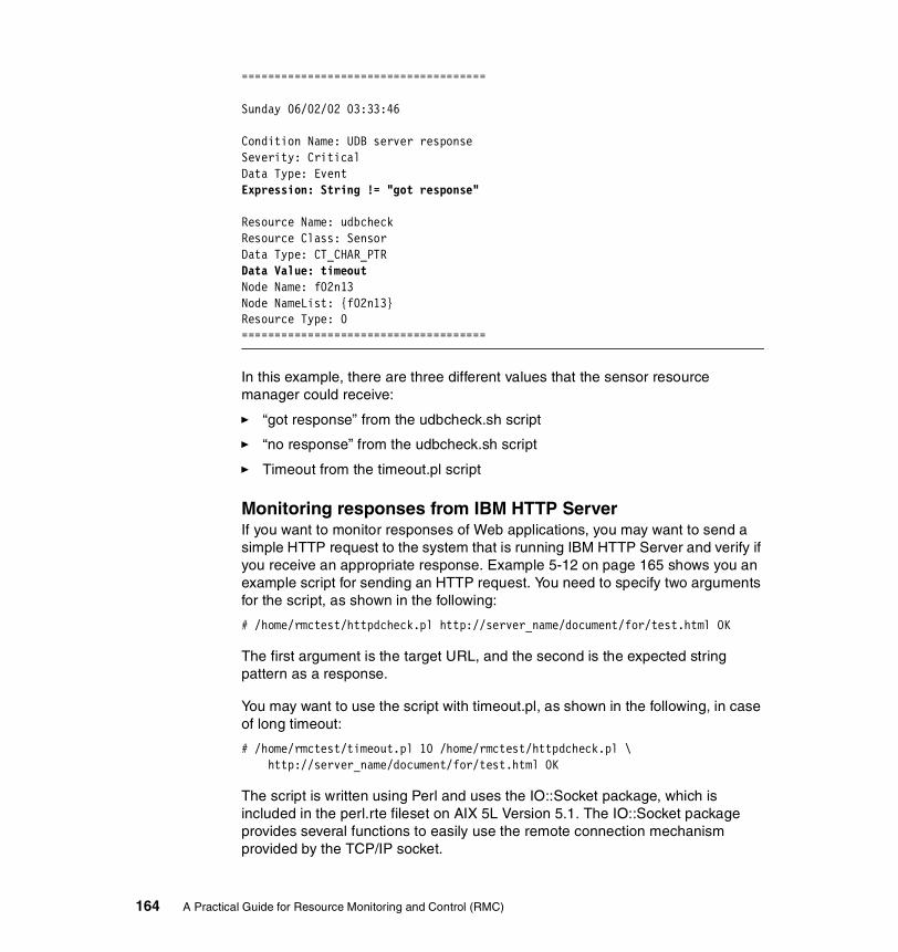
=====================================
Sunday 06/02/02 03:33:46
Condition Name: UDB server responseSeverity: CriticalData Type: EventExpression: String != "got response"
Resource Name: udbcheckResource Class: SensorData Type: CT_CHAR_PTRData Value: timeoutNode Name: f02n13Node NameList: {f02n13}Resource Type: 0=====================================
In this example, there are three different values that the sensor resource manager could receive:
� “got response” from the udbcheck.sh script
� “no response” from the udbcheck.sh script
� Timeout from the timeout.pl script
Monitoring responses from IBM HTTP ServerIf you want to monitor responses of Web applications, you may want to send a simple HTTP request to the system that is running IBM HTTP Server and verify if you receive an appropriate response. Example 5-12 on page 165 shows you an example script for sending an HTTP request. You need to specify two arguments for the script, as shown in the following:
# /home/rmctest/httpdcheck.pl http://server_name/document/for/test.html OK
The first argument is the target URL, and the second is the expected string pattern as a response.
You may want to use the script with timeout.pl, as shown in the following, in case of long timeout:
# /home/rmctest/timeout.pl 10 /home/rmctest/httpdcheck.pl \http://server_name/document/for/test.html OK
The script is written using Perl and uses the IO::Socket package, which is included in the perl.rte fileset on AIX 5L Version 5.1. The IO::Socket package provides several functions to easily use the remote connection mechanism provided by the TCP/IP socket.
164 A Practical Guide for Resource Monitoring and Control (RMC)

Example 5-12 httpdcheck.pl
#!/usr/bin/perluse IO::Socket;
$url=$ARGV[0];$pattern=$ARGV[1];
$url =~ /^http:\/\/([^:\/]+)(:([0-9]+))*((\/.*)*)$/;$host = $1;if ($3 eq "") {
$port = 80;} else {
$port = $3;}if ($4 eq "") {
$path = "/";} else {
$path = $4;}
$ss = new IO::Socket::INET(PeerAddr => $host, PeerPort => $port, Proto => "tcp");
$res=0;if ($ss) {
print $ss "GET $path\r\n";while (<$ss>) {
if ($_ =~ $pattern) {$res=1;
}}
} else {printf("String=\"connection error\"\n");exit(0);
}if ($res) { print "String=\"got response\"\n";} else { print "String=\"bad response\"\n";}close($ss);exit(0);
Chapter 5. Monitoring applications 165
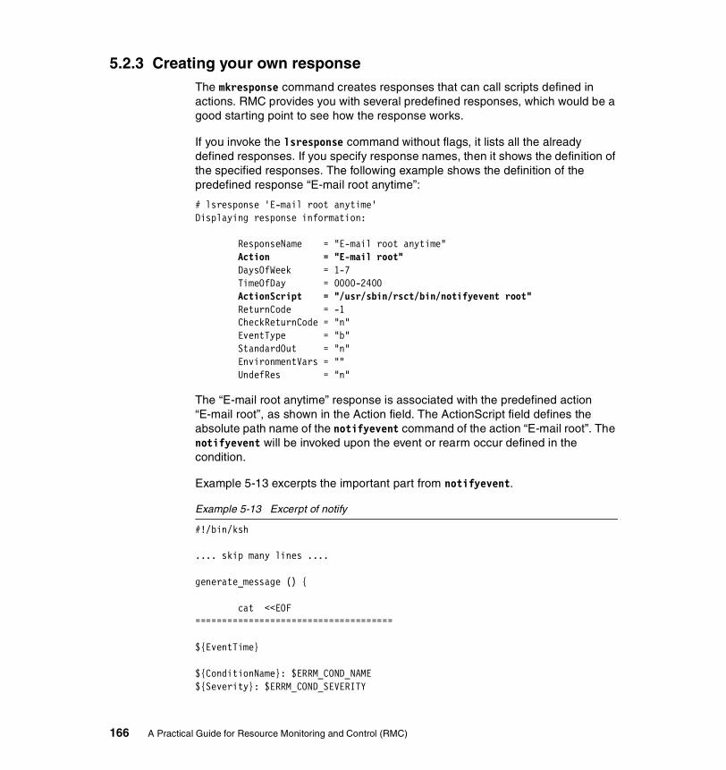
5.2.3 Creating your own responseThe mkresponse command creates responses that can call scripts defined in actions. RMC provides you with several predefined responses, which would be a good starting point to see how the response works.
If you invoke the lsresponse command without flags, it lists all the already defined responses. If you specify response names, then it shows the definition of the specified responses. The following example shows the definition of the predefined response “E-mail root anytime”:
# lsresponse 'E-mail root anytime'Displaying response information:
ResponseName = "E-mail root anytime"Action = "E-mail root"DaysOfWeek = 1-7TimeOfDay = 0000-2400ActionScript = "/usr/sbin/rsct/bin/notifyevent root"ReturnCode = -1CheckReturnCode = "n"EventType = "b"StandardOut = "n"EnvironmentVars = ""UndefRes = "n"
The “E-mail root anytime” response is associated with the predefined action “E-mail root”, as shown in the Action field. The ActionScript field defines the absolute path name of the notifyevent command of the action “E-mail root”. The notifyevent will be invoked upon the event or rearm occur defined in the condition.
Example 5-13 excerpts the important part from notifyevent.
Example 5-13 Excerpt of notify
#!/bin/ksh
.... skip many lines ....
generate_message () {
cat <<EOF=====================================
${EventTime}
${ConditionName}: $ERRM_COND_NAME${Severity}: $ERRM_COND_SEVERITY
166 A Practical Guide for Resource Monitoring and Control (RMC)
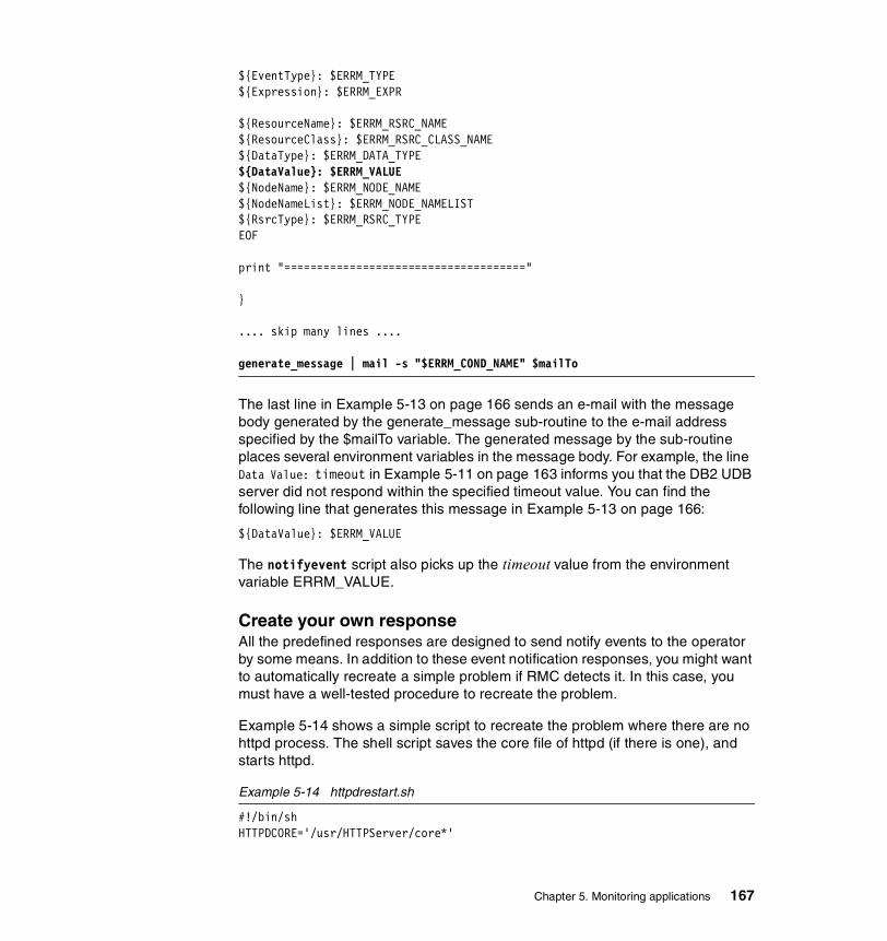
${EventType}: $ERRM_TYPE${Expression}: $ERRM_EXPR
${ResourceName}: $ERRM_RSRC_NAME${ResourceClass}: $ERRM_RSRC_CLASS_NAME${DataType}: $ERRM_DATA_TYPE${DataValue}: $ERRM_VALUE${NodeName}: $ERRM_NODE_NAME${NodeNameList}: $ERRM_NODE_NAMELIST${RsrcType}: $ERRM_RSRC_TYPEEOF
print "====================================="
}
.... skip many lines ....
generate_message | mail -s "$ERRM_COND_NAME" $mailTo
The last line in Example 5-13 on page 166 sends an e-mail with the message body generated by the generate_message sub-routine to the e-mail address specified by the $mailTo variable. The generated message by the sub-routine places several environment variables in the message body. For example, the line Data Value: timeout in Example 5-11 on page 163 informs you that the DB2 UDB server did not respond within the specified timeout value. You can find the following line that generates this message in Example 5-13 on page 166:
${DataValue}: $ERRM_VALUE
The notifyevent script also picks up the timeout value from the environment variable ERRM_VALUE.
Create your own responseAll the predefined responses are designed to send notify events to the operator by some means. In addition to these event notification responses, you might want to automatically recreate a simple problem if RMC detects it. In this case, you must have a well-tested procedure to recreate the problem.
Example 5-14 shows a simple script to recreate the problem where there are no httpd process. The shell script saves the core file of httpd (if there is one), and starts httpd.
Example 5-14 httpdrestart.sh
#!/bin/shHTTPDCORE='/usr/HTTPServer/core*'
Chapter 5. Monitoring applications 167
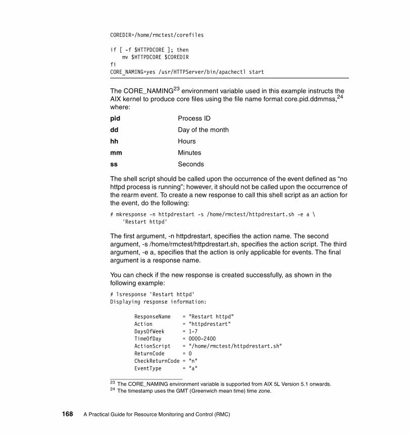
COREDIR=/home/rmctest/corefiles
if [ -f $HTTPDCORE ]; thenmv $HTTPDCORE $COREDIR
fiCORE_NAMING=yes /usr/HTTPServer/bin/apachectl start
The CORE_NAMING23 environment variable used in this example instructs the AIX kernel to produce core files using the file name format core.pid.ddmmss,24 where:
pid Process ID
dd Day of the month
hh Hours
mm Minutes
ss Seconds
The shell script should be called upon the occurrence of the event defined as “no httpd process is running”; however, it should not be called upon the occurrence of the rearm event. To create a new response to call this shell script as an action for the event, do the following:
# mkresponse -n httpdrestart -s /home/rmctest/httpdrestart.sh -e a \'Restart httpd'
The first argument, -n httpdrestart, specifies the action name. The second argument, -s /home/rmctest/httpdrestart.sh, specifies the action script. The third argument, -e a, specifies that the action is only applicable for events. The final argument is a response name.
You can check if the new response is created successfully, as shown in the following example:
# lsresponse 'Restart httpd'Displaying response information:
ResponseName = "Restart httpd"Action = "httpdrestart"DaysOfWeek = 1-7TimeOfDay = 0000-2400ActionScript = "/home/rmctest/httpdrestart.sh"ReturnCode = 0CheckReturnCode = "n"EventType = "a"
23 The CORE_NAMING environment variable is supported from AIX 5L Version 5.1 onwards.24 The timestamp uses the GMT (Greenwich mean time) time zone.
168 A Practical Guide for Resource Monitoring and Control (RMC)

StandardOut = "n"EnvironmentVars = ""UndefRes = "n"
To associate the condition “httpd server state” with the new response “Restart httpd”, do the following:
# mkcondresp 'httpd server state' 'Restart httpd'
Then start the monitoring:
# startcondresp 'httpd server state' 'Restart httpd'
To verify if the httpdrestart response works, do the following steps:
1. Start the httpd process manually:
# CORE_NAMING=yes /usr/HTTPServer/bin/apachectl start/usr/HTTPServer/bin/apachectl start: httpd started
2. Check the process ID of the parent httpd process:
# ps -afe | grep httpd nobody 4042 24046 0 08:41:27 - 0:00 /usr/HTTPServer/bin/httpd imnadm 15232 1 0 May 16 - 0:00 /usr/IMNSearch/httpdlite/httpdlite -r /etc/IMNSearch/httpdlite/httpdlite.conf root 24046 1 0 08:41:26 - 0:00 /usr/HTTPServer/bin/httpd nobody 27246 24046 0 08:41:27 - 0:00 /usr/HTTPServer/bin/httpd nobody 28248 24046 0 08:41:27 - 0:00 /usr/HTTPServer/bin/httpd root 35570 39628 1 08:41:35 pts/1 0:00 grep httpd nobody 49230 24046 0 08:41:27 - 0:00 /usr/HTTPServer/bin/httpd nobody 52756 24046 0 08:41:27 - 0:00 /usr/HTTPServer/bin/httpd
3. Send the SIGSEGV signal to the parent httpd process (in this example, PID 24046) to have it dump the core on purpose:
# kill -SEGV 24046
4. Confirm the core file is produced. The core file name should contain a process ID and a timestamp in GMT:
# ls -l /usr/HTTPServer/core*-rw-r--r-- 1 root system 10151 Jun 19 08:43 /usr/HTTPServer/core.24046.18234327
5. Stop the remaining child httpd processes:
# kill -KILL 4042 27246 28248 49230 52756
6. Wait for a couple of minutes and check to see if httpd has restarted:
# ps -afe | grep httpd nobody 4052 38806 0 08:45:31 - 0:00 /usr/HTTPServer/bin/httpd nobody 6358 38806 0 08:45:31 - 0:00 /usr/HTTPServer/bin/httpd
Chapter 5. Monitoring applications 169
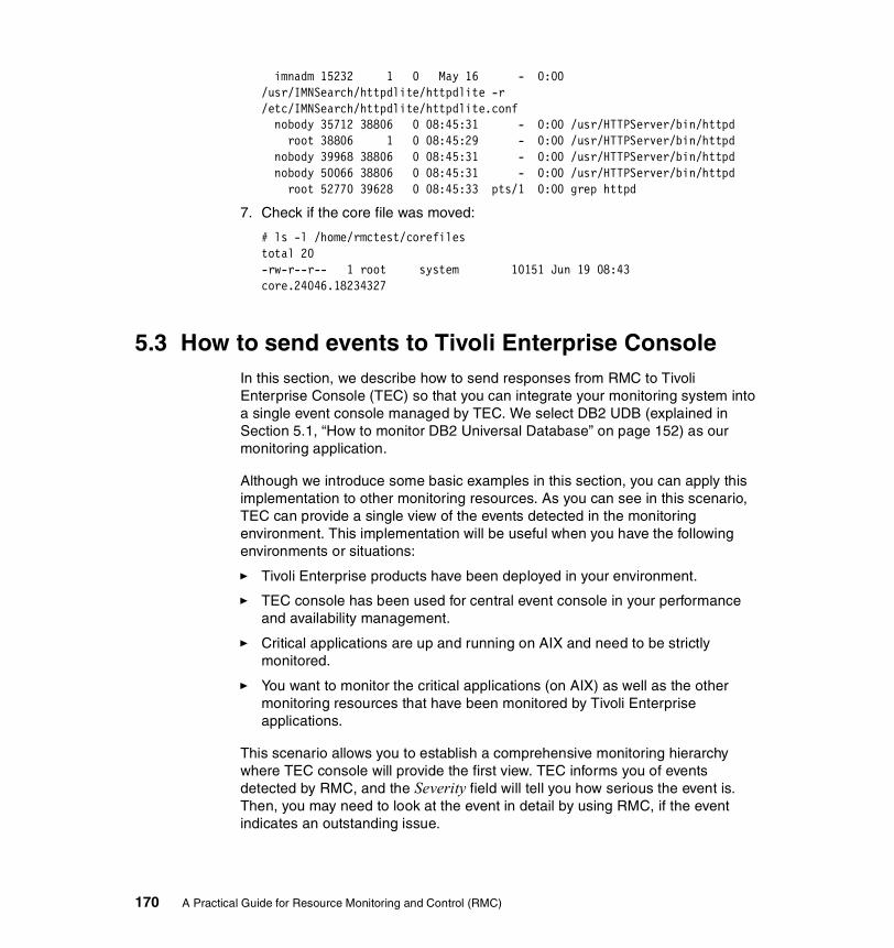
imnadm 15232 1 0 May 16 - 0:00 /usr/IMNSearch/httpdlite/httpdlite -r /etc/IMNSearch/httpdlite/httpdlite.conf nobody 35712 38806 0 08:45:31 - 0:00 /usr/HTTPServer/bin/httpd root 38806 1 0 08:45:29 - 0:00 /usr/HTTPServer/bin/httpd nobody 39968 38806 0 08:45:31 - 0:00 /usr/HTTPServer/bin/httpd nobody 50066 38806 0 08:45:31 - 0:00 /usr/HTTPServer/bin/httpd root 52770 39628 0 08:45:33 pts/1 0:00 grep httpd
7. Check if the core file was moved:
# ls -l /home/rmctest/corefilestotal 20-rw-r--r-- 1 root system 10151 Jun 19 08:43 core.24046.18234327
5.3 How to send events to Tivoli Enterprise ConsoleIn this section, we describe how to send responses from RMC to Tivoli Enterprise Console (TEC) so that you can integrate your monitoring system into a single event console managed by TEC. We select DB2 UDB (explained in Section 5.1, “How to monitor DB2 Universal Database” on page 152) as our monitoring application.
Although we introduce some basic examples in this section, you can apply this implementation to other monitoring resources. As you can see in this scenario, TEC can provide a single view of the events detected in the monitoring environment. This implementation will be useful when you have the following environments or situations:
� Tivoli Enterprise products have been deployed in your environment.
� TEC console has been used for central event console in your performance and availability management.
� Critical applications are up and running on AIX and need to be strictly monitored.
� You want to monitor the critical applications (on AIX) as well as the other monitoring resources that have been monitored by Tivoli Enterprise applications.
This scenario allows you to establish a comprehensive monitoring hierarchy where TEC console will provide the first view. TEC informs you of events detected by RMC, and the Severity field will tell you how serious the event is. Then, you may need to look at the event in detail by using RMC, if the event indicates an outstanding issue.
170 A Practical Guide for Resource Monitoring and Control (RMC)

To implement the RMC action script that sends the response from RMC to TEC, we use the TEC command postemsg in this section. You can also use the wpostemsg command instead of the postemsg command. The difference between these two commands is whether it is secure or not. The wpostemsg command is secure, so the data sent over the network is encrypted, while the postemsg command is insecure. To use wpostemsg, a Tivoli endpoint needs to be installed on the monitored AIX system.
For further information about the postemsg and wpostemsg commands, please refer to the Tivoli Enterprise Console Reference Manual Version 3.7.1, GC32-0666.
5.3.1 System environment of TECFigure 5-2 on page 172 illustrates the configuration used in our test environment. The TEC server (host name is kumiogu) is installed with the following software components:
� AIX Version 4.3.3 Maintenance Level 09
� DB2 Universal Database for AIX Version 7.1 (used for TEC event database)
� Tivoli Management Framework Version 3.7.1 (prerequisite component of TEC)
� Tivoli Enterprise Console Version 3.7.1
We are going to configure an AIX 5L Version 5.1 system (host name is tecclient) that sends a message to the TEC server using RMC.
Note: The postemsg command is provided by TEC. In order to use this command, you have to copy this command from TEC server to the server that will use this command. You have to purchase an additional TEC license on every singe node using the postemsg command. For detailed license information for TEC, please contact your IBM sales representative or business partner.
Chapter 5. Monitoring applications 171
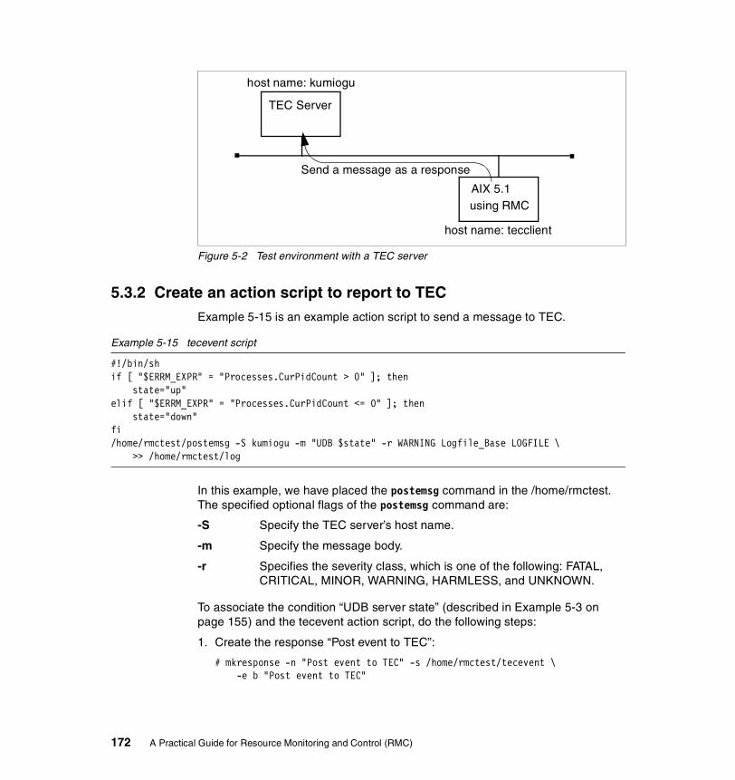
Figure 5-2 Test environment with a TEC server
5.3.2 Create an action script to report to TECExample 5-15 is an example action script to send a message to TEC.
Example 5-15 tecevent script
#!/bin/shif [ "$ERRM_EXPR" = "Processes.CurPidCount > 0" ]; then
state="up"elif [ "$ERRM_EXPR" = "Processes.CurPidCount <= 0" ]; then
state="down"fi/home/rmctest/postemsg -S kumiogu -m "UDB $state" -r WARNING Logfile_Base LOGFILE \
>> /home/rmctest/log
In this example, we have placed the postemsg command in the /home/rmctest. The specified optional flags of the postemsg command are:
-S Specify the TEC server’s host name.
-m Specify the message body.
-r Specifies the severity class, which is one of the following: FATAL, CRITICAL, MINOR, WARNING, HARMLESS, and UNKNOWN.
To associate the condition “UDB server state” (described in Example 5-3 on page 155) and the tecevent action script, do the following steps:
1. Create the response “Post event to TEC”:
# mkresponse -n "Post event to TEC" -s /home/rmctest/tecevent \-e b "Post event to TEC"
TEC Server
AIX 5.1using RMC
host name: kumiogu
Send a message as a response
host name: tecclient
172 A Practical Guide for Resource Monitoring and Control (RMC)
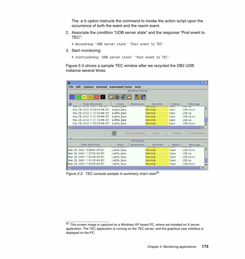
The -e b option instructs the command to invoke the action script upon the occurrence of both the event and the rearm event.
2. Associate the condition “UDB server state” and the response “Post event to TEC”:
# mkcondresp 'UDB server state' 'Post event to TEC'
3. Start monitoring:
# startcondresp 'UDB server state' 'Post event to TEC'
Figure 5-3 shows a sample TEC window after we recycled the DB2 UDB instance several times.
Figure 5-3 TEC console sample in summery chart view25
25 This screen image is captured on a Windows XP based PC, where we installed an X server application. The TEC application is running on the TEC server, and the graphical user interface is displayed on the PC.
Chapter 5. Monitoring applications 173

174 A Practical Guide for Resource Monitoring and Control (RMC)

Appendix A. Filesets level information
This appendix provides detailed level information about the filesets used in our test environment.
At the time of writing of this redbook, the recommended maintenance levels (RMLs) 5100-01 and 5100-02 are available for AIX 5L Version 5.1 and they are installed on our test systems:
# instfix -i | grep ML All filesets for 5.0.0.0_AIX_ML were found. All filesets for 5.1.0.0_AIX_ML were found. All filesets for 5.1.0.0_AIX_ML were found. All filesets for 5100-01_AIX_ML were found. All filesets for 5100-02_AIX_ML were found.
Therefore, the oslevel -r command returns the following output:
# oslevel -r5100-02
This appendix contains the following:
� “RSCT and RMC filesets level” on page 176
� “Web-based System Manager filesets level” on page 177
A
© Copyright IBM Corp. 2002. All rights reserved. 175
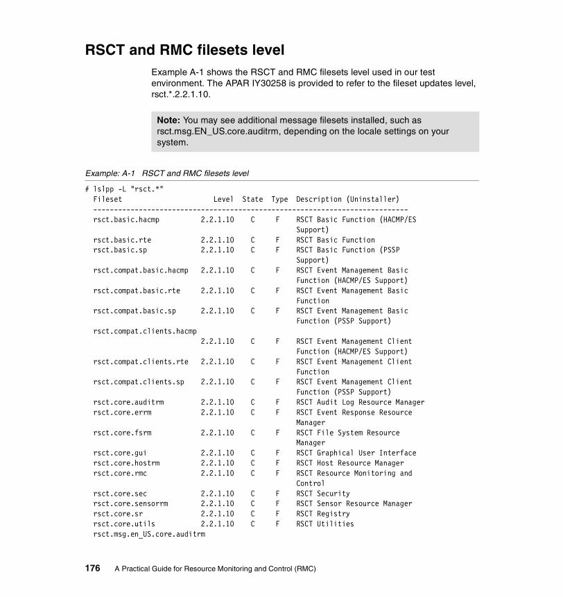
RSCT and RMC filesets levelExample A-1 shows the RSCT and RMC filesets level used in our test environment. The APAR IY30258 is provided to refer to the fileset updates level, rsct.*.2.2.1.10.
Example: A-1 RSCT and RMC filesets level
# lslpp -L "rsct.*"Fileset Level State Type Description (Uninstaller)----------------------------------------------------------------------------rsct.basic.hacmp 2.2.1.10 C F RSCT Basic Function (HACMP/ES
Support) rsct.basic.rte 2.2.1.10 C F RSCT Basic Function rsct.basic.sp 2.2.1.10 C F RSCT Basic Function (PSSP Support) rsct.compat.basic.hacmp 2.2.1.10 C F RSCT Event Management Basic Function (HACMP/ES Support) rsct.compat.basic.rte 2.2.1.10 C F RSCT Event Management Basic Function rsct.compat.basic.sp 2.2.1.10 C F RSCT Event Management Basic Function (PSSP Support) rsct.compat.clients.hacmp 2.2.1.10 C F RSCT Event Management Client Function (HACMP/ES Support) rsct.compat.clients.rte 2.2.1.10 C F RSCT Event Management Client Function rsct.compat.clients.sp 2.2.1.10 C F RSCT Event Management Client Function (PSSP Support) rsct.core.auditrm 2.2.1.10 C F RSCT Audit Log Resource Manager rsct.core.errm 2.2.1.10 C F RSCT Event Response Resource Manager rsct.core.fsrm 2.2.1.10 C F RSCT File System Resource Manager rsct.core.gui 2.2.1.10 C F RSCT Graphical User Interface rsct.core.hostrm 2.2.1.10 C F RSCT Host Resource Manager rsct.core.rmc 2.2.1.10 C F RSCT Resource Monitoring and Control rsct.core.sec 2.2.1.10 C F RSCT Security rsct.core.sensorrm 2.2.1.10 C F RSCT Sensor Resource Manager rsct.core.sr 2.2.1.10 C F RSCT Registry rsct.core.utils 2.2.1.10 C F RSCT Utilitiesrsct.msg.en_US.core.auditrm
Note: You may see additional message filesets installed, such as rsct.msg.EN_US.core.auditrm, depending on the locale settings on your system.
176 A Practical Guide for Resource Monitoring and Control (RMC)

2.2.0.0 C F RSCT Audit Log RM Msgs - U.S. English rsct.msg.en_US.core.errm 2.2.0.0 C F RSCT Event Response RM Msgs - U.S. English rsct.msg.en_US.core.fsrm 2.2.0.0 C F RSCT File System RM Msgs - U.S. English rsct.msg.en_US.core.gui 2.2.0.0 C F RSCT GUI Msgs - U.S. English rsct.msg.en_US.core.hostrm 2.2.0.0 C F RSCT Host RM Msgs - U.S. English rsct.msg.en_US.core.rmc 2.2.0.0 C F RSCT RMC Msgs - U.S. English rsct.msg.en_US.core.sec 2.2.0.0 C F RSCT Security Msgs - U.S. English rsct.msg.en_US.core.sensorrm 2.2.0.0 C F RSCT Sensor RM Msgs - U.S. English rsct.msg.en_US.core.sr 2.2.0.0 C F RSCT Registry Msgs - U.S. English rsct.msg.en_US.core.utils 2.2.0.0 C F RSCT Utilities Msgs - U.S. English
State codes: A -- Applied. B -- Broken. C -- Committed. O -- Obsolete. (partially migrated to newer version) ? -- Inconsistent State...Run lppchk -v.
Type codes: F -- Installp Fileset P -- Product C -- Component T -- Feature R -- RPM Package
Web-based System Manager filesets levelExample A-2 shows the Web-based System Manager filesets level used in our test environment.
Example: A-2 Web-based System Manager filesets level
# lslpp -L 'sysmgt.websm.*' Fileset Level State Type Description (Uninstaller) ---------------------------------------------------------------------------- sysmgt.websm.apps 5.1.0.25 C F Web-based System Manager Applications
Appendix A. Filesets level information 177

sysmgt.websm.diag 5.1.0.25 C F Web-based System Manager Diagnostic Applications sysmgt.websm.framework 5.1.0.25 C F Web-based System Manager Client/Server Support sysmgt.websm.icons 5.1.0.25 C F Web-based System Manager Icons sysmgt.websm.rte 5.1.0.25 C F Web-based System Manager Runtime Environment sysmgt.websm.webaccess 5.1.0.25 C F WebSM Web Access Enablement
State codes: A -- Applied. B -- Broken. C -- Committed. O -- Obsolete. (partially migrated to newer version) ? -- Inconsistent State...Run lppchk -v.
Type codes: F -- Installp Fileset P -- Product C -- Component T -- Feature R -- RPM Package
178 A Practical Guide for Resource Monitoring and Control (RMC)
Appendix B. Useful information
This appendix contains useful information about Resource Monitoring and Control, including:
� “rsct.core.README” on page 180
� “Perl/Expect installation” on page 184
B
© Copyright IBM Corp. 2002. All rights reserved. 179
rsct.core.READMEThis section includes an excerpt of the rsct.core.README file provided with AIX 5L Version 5.1.
DescriptionThis is the README for RSCT Resource Monitoring and Control, Version 2 Release 2. It contains the latest information about this release, including installation pointers, documentation updates, and restrictions. The information in this README supersedes any of the previously documented instructions for this release.
This README pertains to all the filesets included with RSCT Resource Monitoring and Control 2.2. They are:
� rsct.core.auditrm
� rsct.core.errm
� rsct.core.fsrm
� rsct.core.gui
� rsct.core.hostrm
� rsct.core.rmc
� rsct.core.sec
� rsct.core.sensorrm
� rsct.core.sr
� rsct.core.utils
Installation informationThe Reliable Scalable Cluster Technology (RSCT) requires the installation of several filesets, including the bos.perf.perfstat, bos.rte, bos.rte.iconv, bos.iconv.com, bos.iconv.ucs.com, perl.rte, and bos.net.tcp.client filesets. These requirements are enforced by having a co-requisite of bos.perf.perfstat and a prerequisite of the others. These filesets are shipped with AIX 5L Version 5.1.
Note: We slightly changed the contents from the original README file on purpose, mainly to improve the readability. We also deliberately did not include legal information in here for the limited space of this redbook. Please print the README file on your system to confirm the latest information.
180 A Practical Guide for Resource Monitoring and Control (RMC)

There is a special procedure when RSCT is installed from a System Image or NIM. Since RSCT stores node specific configuration information in the /etc and /var/ct/cfg directories, creating a system (mksysb) image from a node and restoring it to another node may cause unexpected behavior from the RMC subsystem. Therefore, one of the following methods should be used for installation or upgrading using a system image:
1. Build a system image, including a /etc/firstboot script.
Before creating a system image, /etc/firstboot must be edited to include /usr/sbin/rsct/install/bin/recfgct. The /etc/firstboot script will be executed during the first boot after the installation. A system image created using this method may not be used for an upgrade.
2. Use NIM resource type (script).
The NIM installation procedure provides a method to execute some actions after the installation. Include /usr/sbin/rsct/install/bin/recfgct in this script.
3. On PSSP, use firstboot.cust script.
There is a sample script, /usr/lpp/ssp/samples/firstboot.cust, which is designed to be used by the user as a guide for some functions that might be performed after a node has been network installed, and after it boots for the first time. Add /usr/sbin/rsct/install/bin/recfgct to the /tftpboot/firstboot.cust script.
4. Manually reset the node specific configuration information.
After the installation, invoke the /usr/sbin/rsct/install/bin/recfgct command, which will regenerate the node specific configuration information.
AdvisoriesThe following advisories should be noted.
Backing up the /var/ct directoryThe /var/ct directory and all its subdirectories should be backed up periodically. These directories are used by the RMC subsystems to store resource persistent data and other configuration information.
In addition, if major configuration changes are made via CSM commands or the Web-based System Manager Monitoring application, a backup of this directory should be performed.
Perform the following steps to do a backup:
1. Execute the following command to stop the RMC subsystems. The command does not complete until all RMC subsystems are stopped:
Appendix B. Useful information 181

# /usr/sbin/rsct/bin/rmcctrl -z
2. Perform a backup of the /var/ct directory.
3. Execute the following command to restart the RMC subsystems:
# /usr/sbin/rsct/bin/rmcctrl -s
To restore the /var/ct/ directory, perform the following steps:
1. Execute the following command to stop the RMC subsystems:
# /usr/sbin/rsct/bin/rmcctrl -z
2. Restore the /var/ct directory.
3. Execute the following command to restart the RMC subsystems:
# /usr/sbin/rsct/bin/rmcctrl -s
Modifying a Cluster Security configuration fileThe Cluster Security (CtSec) component of RSCT provides a sub-service that performs authentication functions based on host identities. This sub-service, called ctcas, comes with a text formatted configuration file shipped in /usr/sbin/rsct/cfg/ctcasd.cfg. Within this file are definitions of the maximum number of threads the daemon may create, the minimum number of threads to keep running when the daemon is idle, the path names of the default host private and public keyfiles, and what default host identifier key generation method is to be used by the ctcas service. If a system administrator wishes to modify any of these values, the /usr/sbin/rsct/cfg/ctcasd.cfg file must be copied to the file /var/ct/cfg/ctcasd.cfg, and any desired modification must be made to the /var/ct/cfg/ctcasd.cfg version. The default file, /usr/sbin/rsct/cfg/ctcasd.cfg, must not be modified. When the ctcas sub-service is started, it will search first for the /var/ct/cfg/ctcasd.cfg file, and then for the /usr/sbin/rsct/cfg/ctcasd.cfg file, if the former is not found.
Memory requirement for Web-based System ManagerThe minimum memory requirement to run a Web-based System Manager session is 256 MB. However, if you plan to run the Monitoring application from more than one Web-based System Manger session at the same time on a system, more than 256 MB of memory is recommended to enhance performance.
Predefined responsesWhen the responses specified with the predefined notifyevent, wallevent, or logevent scripts are used in a Japanese locale, English should be used for all input fields in the monitoring plug-in and for all options on the command line. This restriction is necessary since the commands invoked in these sample scripts do not handle Japanese characters correctly in all cases. If you modify these scripts
182 A Practical Guide for Resource Monitoring and Control (RMC)

or create new ones to handle double-byte characters correctly, then this restriction does not apply.
Three new Event Response scripts, ewallevent, enotifyevent, and elogevent, are provided in the directory /usr/sbin/rsct/bin. These scripts provide the same function as the predefined scripts wallevent, notifyevent, and logevent. The predefined scripts report events in the language of the system’s default locale. In contrast, the three new scripts always report events in English. User specified text, such as condition names or response names, is reported as specified by the user; such text might not be in English.
You can use the new scripts while defining responses from the Monitoring plug-in of a Web-based System Manager session or using the ERRM CLI:
� From the Monitoring plug-in, bring up a new Response property dialog and add a new action by selecting the “Run program” option from the Action dialog box. Provide the absolute path name of a new script, for example, /usr/sbin/rsct/bin/elogevent. If an event occurs for a condition that uses the response, the response will take place, and the program specified in the response will run; in other words, the elogevent script will be invoked, and the event will be logged into the file in English.
� Similarly, from the CLI, specify the new script’s absolute path name with the -s option when you add a new action to a response using the ERRM commands mkresponse or chresponse.
Display limitations for Web-based System Manager� Environment variables set for a response via the command line will not be
displayed in the Web-based System Manager.
� The ManagementScope persistent attribute of the IBM.Condition class is not displayed in the Condition property dialog box of the Web-based System Manager.
� The Web-based System Manager will only display conditions whose ManagementScope persistent attribute has a value of 1 (meaning local scope).
� Users are not able to create a response with no actions using the Web-based System Manager. However, such responses created via the command line will be available for monitoring via the Web-based System Manager.
World Wide Web access informationThe RSCT documentation is available as Portable Document Format (PDF) files from the IBM Publications Web site:
http://www.ibm.com/shop/publications/order
Appendix B. Useful information 183
The RSCT books are also available from the URL:
http://www.ibm.com/servers/eserver/clusters/library
You can view or download the following books:
� IBM RSCT: Group Services Programming Guide and Reference, SA22-7888
� IBM RSCT for AIX: Guide and Reference, SA22-7889
� IBM RSCT for AIX: Technical Reference, SA22-7890
� IBM RSCT for AIX: Messages, GA22-7891
To view the RSCT PDF publications, you need access to the Adobe Acrobat Reader. The Acrobat Reader is freely available from the Adobe Web site at:
http://www.adobe.com
To successfully print a large PDF file (approximately 300 or more pages) from the Adobe Acrobat reader, you may need to select the “Download Fonts Once” button on the Print window.
Perl/Expect installationTo install Perl/Expect and related modules, visit the Comprehensive Perl Archive Network (CPAN) site that archives all the modules for Perl. You can access CPAN at the following URL:
http://www.cpan.org
The following steps explain how to install Perl/Expect on AIX 5L Version 5.1:
1. Download the following three modules26 from CPAN:
– Expect-1.15.tar.gz
– IO-Stty-IO-Stty-.02.tar.gz
– IO-Tty-1.02.tar.gz
2. Install IBM C compiler Version 5 and the GNU gzip27 command.
3. Make sure you have a minimum of 1 MB free space in /usr.
4. Install these modules, as shown in the following example:
$ cd /work/src/Expect_modules$ gzip -d -c ../source_package/IO-Tty-1.02.tar.gz | tar -xf -$ cd IO-Tty-1.02$ perl Makefile.PL
26 You might see newer version of these modules on CPAN.27 The GNU gzip command is provided by AIX toolbox for Linux applications.
184 A Practical Guide for Resource Monitoring and Control (RMC)
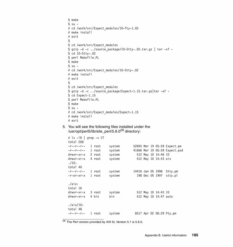
$ make$ su -# cd /work/src/Expect_modules/IO-Tty-1.02# make install# exit$$ cd /work/src/Expect_modules$ gzip -d -c ../source_package/IO-Stty-.02.tar.gz | tar -xf -$ cd IO-Stty-.02$ perl Makefile.PL$ make$ su -# cd /work/src/Expect_modules/IO-Stty-.02# make install# exit$$ cd /work/src/Expect_modules$ gzip -d -c ../source_package/Expect-1.15.tar.gz|tar -xf -$ cd Expect-1.15$ perl Makefile.PL$ make$ su -# cd /work/src/Expect_modules/Expect-1.15# make install# exit
5. You will see the following files installed under the /usr/opt/perl5/lib/site_perl/5.6.028 directory:
# ls -lR | grep -v CTtotal 208-r--r--r-- 1 root system 52845 Mar 19 05:59 Expect.pm-r--r--r-- 1 root system 41666 Mar 19 05:59 Expect.poddrwxr-xr-x 2 root system 512 May 10 14:46 IOdrwxr-xr-x 4 root system 512 May 10 14:43 aix./IO:total 40-r--r--r-- 1 root system 14416 Jan 05 1998 Stty.pm-r-xr-xr-x 1 root system 198 Dec 05 1997 stty.pl
./aix:total 16drwxr-xr-x 3 root system 512 May 10 14:43 IOdrwxr-xr-x 4 bin bin 512 May 10 14:47 auto
./aix/IO:total 48-r--r--r-- 1 root system 8517 Apr 02 06:29 Pty.pm
28 The Perl version provided by AIX 5L Version 5.1 is 5.6.0.
Appendix B. Useful information 185
drwxr-xr-x 2 root system 512 May 10 14:43 Tty-r--r--r-- 1 root system 7277 Apr 02 06:29 Tty.pm
./aix/IO/Tty:total 16-r--r--r-- 1 root system 7184 May 10 14:37 Constant.pm
./aix/auto:total 24drwxr-xr-x 2 root system 512 May 10 14:47 Expectdrwxr-xr-x 4 root system 512 May 10 14:46 IO
./aix/auto/Expect:total 8-rw-r--r-- 1 root system 120 May 10 14:47 .packlist
./aix/auto/IO:total 16drwxr-xr-x 2 root system 512 May 10 14:46 Sttydrwxr-xr-x 2 root system 512 May 10 14:43 Tty
./aix/auto/IO/Stty:total 8-rw-r--r-- 1 root system 92 May 10 14:46 .packlist
./aix/auto/IO/Tty:total 80-rw-r--r-- 1 root system 372 May 10 14:43 .packlist-r--r--r-- 1 root system 0 May 10 14:38 Tty.bs-r-xr-xr-x 1 root system 34222 May 10 14:38 Tty.so
186 A Practical Guide for Resource Monitoring and Control (RMC)

acronyms
ACL Access Control List
API Application Program Interface
CDE Common Desktop Environment
CPAN Comprehensive Perl Archive Network
CSM IBM Cluster Systems Management
CtSec Cluster Security
DB2 UDB DB2 Universal Database for AIX
DMSRM Domain Resource Manager
ERRM Event Response Resource Manager
GS Group Service
HA High Availability
HAEM High Availability Event Monitoring
IBM International Business Machines Corporation
IHS IBM HTTP Server
ITSO International Technical Support Organization
IW Independent Workstation
PDF Portable Document Format
PSSP Parallel System Support Program
RMC Resource Monitoring Control
RSCT Reliable Scalable Cluster Technology
SD Structured Data
SP Scalable Parallel
SRC System Resource Controller
TEC Tivoli Enterprise Console
Abbreviations and
© Copyright IBM Corp. 2002. All rights reserved.
TS Topology Service
187

188 A Practical Guide for Resource Monitoring and Control (RMC)

Related publications
The publications listed in this section are considered particularly suitable for a more detailed discussion of the topics covered in this redbook.
IBM RedbooksFor information on ordering these publications, see “How to get IBM Redbooks” on page 190.
� GPFS on AIX Clusters: High Performance FIle System Administration Simplified, SG24-6035
� Linux Clustering with CSM and GPFS, SG24-6601
� Managing AIX Server Farms, SG24-6606
� PSSP Version 3 Survival Guide, SG24-5344
� RS/6000 SP Cluster: The Path to Universal Clustering, SG24-5374
� RSCT Group Services: Programming Cluster Applications, SG24-5523
Other resourcesThese publications are also relevant as further information sources:
� AIX 5L Version 5.1 Installation Guides: Installation Guide*
� AIX 5L Version 5.1 Installation Guides: Network Installation Management Guide and Reference*
� AIX 5L Version 5.1 Reference Documentation: Commands Reference*
� AIX 5L Version 5.1 System Management Guides: AIX 5L Version 5.1 Web-based System Manager Administration Guide*
� AIX 5L Version 5.1 System Management Guides: Operating System and Devices*
� IBM RSCT: Group Services Programming Guide and Reference, SA22-7888
� IBM RSCT for AIX: Guide and Reference, SA22-7889
� IBM RSCT for AIX: Messages, SA22-7891
� IBM RSCT for AIX: Technical Reference, SA22-7890
© Copyright IBM Corp. 2002. All rights reserved. 189
You can access all of the pSeries hardware related documentation through the Internet at the following URL:
http://www.ibm.com/servers/eserver/pseries/library/hardware_docs/index.html
You can also access all of the AIX documentation through the Internet at the following URL:
http://www.ibm.com/servers/aix/library
The publications marked with * in the list are located on the documentation CD-ROM that ships with the AIX operating system:
Referenced Web sitesThese Web sites are also relevant as further information sources:
� Adobe Systems
http://www.adobe.com
� AIX 5L Version 5.1 Web-based System Manager
http://www-1.ibm.com/servers/aix/os/wsm/51/
� Comprehensive Perl Archive Network
http://www.cpan.org
� IBM ^ Cluster
http://www-1.ibm.com/servers/eserver/clusters/
� IBM ^ pSeries Resource Library
http://www-1.ibm.com/servers/eserver/pseries/library
� IBM Publications Center
http://www.ibm.com/shop/publications/order
How to get IBM RedbooksYou can order hardcopy Redbooks, as well as view, download, or search for Redbooks at the following Web site:
ibm.com/redbooks
You can also download additional materials (code samples or diskette/CD-ROM images) from that site.
190 A Practical Guide for Resource Monitoring and Control (RMC)190 A Practical Guide for Resource Monitoring and Control (RMC)

IBM Redbooks collectionsRedbooks are also available on CD-ROMs. Click the CD-ROMs button on the Redbooks Web site for information about all the CD-ROMs offered, as well as updates and formats.
Related publications 191

192 A Practical Guide for Resource Monitoring and Control (RMC)192 A Practical Guide for Resource Monitoring and Control (RMC)
Index
Symbols!~ 103# 103$PATH 35% 103/dev/hd6 115/etc/firstboot 181/etc/inittab 114/home/remount 83/home/rmctest/program.sh 157/SharedTools 94/tmp/inform.log 91/usr/bin 35/usr/lpp/ssp/samples/firstboot.cust 181/usr/sbin/rsct 35/usr/sbin/rsct/bin 35/usr/sbin/rsct/cfg/ctrmc.acls 143/usr/sbin/rsct/install/bin/recfgct 181/var/ct 35/var/ct/ 36/var/ct/cfg/ct_has.thl 149/var/ct/cfg/ctrmc.acls 144=? 103=~ 103@P 136^ 105_ 103~? 103
AAccess Control List 143ACL 143action 32ActionScript field 133Add Action 84Adding a node to the cluster 109additional time-out logic 161addrpnode 109aggregate data type 22AIX errorlog 26AIX kernel 168AIX security audit function 26AIX toolbox for Linux applications 184
© Copyright IBM Corp. 2002. All rights reserved.
AIX user-id 124All day 70All day Everyday 85All Events 56alog command 26APAR IY30258 176architecture 16array 22association 34ATM 29Attempt remount 82attribute 21Audit Log commands 142Audit Log resource manager 26authentication 143authorization 143automatic 101
BBacking up the /var/ct Directory 181base data type 21big-file-enabled 120Bringing a node online 110Bringing the cluster online 108Broadcast message 67
Ccaret character 105CDE 39chcondition 139CheckReturnCode 134chresponse 141chrsrc 115chsensor 125CLI 17Client-Server mode 38Cluster Security 182Cluster Technology 16cluster_id 36clustered environment 5CMD 153command line history 19Command line interface 17
193

Common Desktop Environment 39commonly used command flags 99Comprehensive Perl Archive Network 184condition 30Condition Properties dialog 59Condition property dialog 45Conditions plug-in 48condresp 126ConfigChanged 62core file 167CORE_NAMING 168CPAN 184Create your own response 167Creating the cluster 107CSM 7CSM agent resource manager 6CSM Agent RM 6CT 16CT_CONTACT 95ct_has.pkf 148ct_has.qkf 148CT_MANAGEMENT_SCOPE 95ctcas 182CtSec 182ctskeygen 148ctsthl 149Current Events 56
DDay of Week 68, 85DB2 Universal Database 151db2admin 155db2alert.log 152db2diag.log 152db2gds 153–154db2ipccm 153db2resyn 153db2srvlst 154db2sysc 153–154db2tcpcm 153db2wdog 153DEFAULT 147Define your own sensor 156description of a resource class 119Display Limitations for Web-based System Manager 183DMSRM 6DNS 94
DNS domain 94do loop 122domain resource manager 6dot 103double-quote characters 121dynamic attribute 23
Eecho command 117Edit Responses to Start Monitoring 50elogevent 33e-mail 159e-mail address 167enotifyevent 33ERRM 24ERRM_ 138ERRM_RSRC_NAME 33ERRM_VALUE 167Ethernet 29event database 171event expression 76Event Monitoring 4Event Properties dialog 56Event Response resource manager 24event sensor command 157EventType 134ewallevent 33exchange public keys 107Expect language 162Expect.pm 162Expect/Perl 162expecting string pattern 164expression 30extended regular expression operators 103
Ffalse 101FDDI 29File System resource manager 28fileset 8firewall 12FQDN 94full path name 122fully qualified domain name 94
Ggeneric RMC commands 114
194 A Practical Guide for Resource Monitoring and Control (RMC)
geographical aspects 95Global daemon spawner 153GMT 168GNU gzip 184Graphical user interface 17Greenwich mean time 168Group Service 4GS 4GUI 17
HHA 4HAEM 4High Availability 4host resource manager 28hostname command 94HTTP request 164httpcheck 157httpd 167httpd server state 158httpdrestart 169
IIBM C compiler Version 5 184IBM Cluster Systems Management 7IBM HTTP Server 151IBM.ATMDevice 29IBM.EthernetDevice 29IBM.FDDIDevice 29IBM.Host 28IBM.HostPublic 28IBM.PagingDevice 28IBM.PhysicalVolume 28IBM.Processor 28IBM.Program 29IBM.Sensor resource class 156IBM.TokenRingDevice 29IHS 151Independent Workstation 35instfix 175Int32 158IO
Socket package 164itsc.austin.ibm.com 94IW 35
JJapanese characters 182JFS 120
Llarge file enabled feature 120Linux operating system 7listener process 153locale 113location concepts 127Log File 67Log On dialog 41logevent 32logevent action 26logical volume 115lsactdef 106, 115lsaudrec 142lscondition 117, 127lscondresp 134lsresponse 132lsrpdomain 108lsrsrc 115lsrsrc command 96lsrsrcdef 106, 119lssensor 123lssrc 112
Mmanagement domain 5Management Environment tree 43management server 7MaxSize attribute 142Memory Requirement for Web-based System Man-ager 182message body 167message catalog 9mgr_name entry 120MgtScope 131mkcondition 117, 135mkcondresp 139mkresponse 137, 156mkrpdomain 107mkrsrc 115mksensor 125mksysb 181Modifying a Cluster Security Configuration File 182monitored property 47Monitoring plug-in 48
Index 195

MonitorStatus attribute 131MountDir 102MountPoint 102
NNavigation Area 41new condition 71new response 80NIM 181NIM resource type 181nlssrc 113node 27Node attribute 131NodeNames attributes 131not valid for define 116notifyevent 32NumUsers 123, 136
OOpState 62optional for define 116oslevel 175
Ppaging space 115Parallel System Support Program 4PATH 137Pattern match operators 102pattern matching 102PC applet mode 38PC client 40PC client mode 38PctTotalTimeIdle 136peer domain 5percent sign 103PercentINodeUsed 62PercentTotUsed 62, 102Perl 162Perl module 162persistent attribute 22postemsg 171pound sign 103predefined actions 32Predefined Responses 182Preparing your node security 107preprpnode 107ps 152
pSeries xiiiPSSP 4public 116public-key based security mechanism 107
Qquery request 160quorum 27
Rread only 116rearm expression 76recommended maintenance level 175Redbooks Web site 190
Contact us xvrefresh 113refresh command 121RefreshInterval 157regular expression 102Reinstall RMC 12Reliable Scalable Cluster Technology 4Remote node access 147Removing a cluster 112Removing a node 111required for define 116resource 20resource class 21resource manager 23Resource Monitoring and Control 1Resource Monitoring and Control application user interface 17Resource_Data_Input 106ResourceHandle 117response 33Resync agent process 153ReturnCode 134rmaudrec 142RMC 1RMC API 17RMC audit log 26RMC client 18RMC subsystem 3rmcctrl 113rmcondition 141rmcondresp 141RML 175rmresponse 141rmrpdomain 112
196 A Practical Guide for Resource Monitoring and Control (RMC)

rmrpnode 111rmrsrc 115rmsensor 125root privilege 146RS/6000 Scalable Parallel 4RSCT 4rsct grou 113RSCT RMC 3rsct.core.auditrm 180rsct.core.errm 180rsct.core.fsrm 180rsct.core.gui 180rsct.core.hostrm 180rsct.core.README 180rsct.core.rmc 180rsct.core.sec 180rsct.core.sensorrm 180rsct.core.sr 180rsct.core.utils 180rsct_rm group 113rsync 94Run Program 67
SSD 22sed 121selectable 116selection string 100Send mail 67sensor resource manager 29, 157Severity field 170severity level 77SIGSEGV 169SMIT 19smitty 132snap 89Software Update Protocol 94SP 4SQL-like syntax operators 103SRC 112stand-alone 5Stand-alone application mode 38StandardOut 134star 103startcondresp 139startrpnode 110startsrc 113status bar 44
stopcondresp 141Stopping (offline) a cluster 111Stopping (offline) a node 110stoprpdomain 111stopsrc 113String 158structured data 22substring match 129SUP 94syscat.tables 160syslog 26system bundle 9system controller process 153System Image 181system resource controller 112
Ttarget URL 164TCP port 12TCP/IP socket. 164TEC 170temporary file 132test environment 94tiled display 44Time of Day 68, 85time zone 168timeout value 162timeout.pl 162title bar 44Tivoli endpoint 171Tivoli Enterprise Console 170Tivoli Enterprise products 170Token-Ring 29Topas 135topas 131Topology Service 4touch 149true 101TS 4
UUDB 151udbcheck.sh 162umount /work04. 91underscore 103Uninstall RMC 12UNIX identity-based credentials 113user defined environment variables 138
Index 197

Username attribute 124
Vvmstat 131
Wwall command 33wallevent 32wallevent command 67Watchdog process 153Web-based System Manager 19, 37When in Effect 68wild cards 103wpostemsg 171wsm& 38
XX Window system 38
Yyes command 53
198 A Practical Guide for Resource Monitoring and Control (RMC)

A Practical Guide for Resource Monitoring and Control (RM
C)


®
SG24-6615-00 ISBN 0738426695
INTERNATIONAL TECHNICALSUPPORTORGANIZATION
BUILDING TECHNICALINFORMATION BASED ONPRACTICAL EXPERIENCE
IBM Redbooks are developed by the IBM International Technical Support Organization. Experts from IBM, Customers and Partners from around the world create timely technical information based on realistic scenarios. Specific recommendations are provided to help you implement IT solutions more effectively in your environment.
For more information:ibm.com/redbooks
A Practical Guide forResource Monitoring and Control (RMC)
Configure RMC using the Web-based System Manager
Comprehensive examples of the RMC command line interface
Practical examples on how to monitor your applications
This redbook discusses the capabilities of Resource Monitoring and Control (RMC) that enables you to monitor various resources of your system and create automated responses to changing conditions of those resources.RMC is provided by the AIX 5L Version 5.1 and later operating systems and is a subset of the functionality available in Reliable Scalable Cluster Technology (RSCT). RSCT provides a set of software components that together support a powerful and flexible environment for clustering systems.The focus of this redbook is to explain the architecture and components of RMC and its usage by providing with practical examples in several different configurations, including:
- Introduction- Architecture and components- Quick start: using RMC- RMC command line interface- Monitoring applications
This redbook is an ideal desk side reference for IBM employees, Business Partners, and customer system administrators or technical specialists who exploit RMC to manage IBM ^ pSeries servers running AIX 5L Version 5.1.
Back cover