A Portable Sketching Robot Based on Artificial …A Portable Sketching Robot Based on Artificial...
13
Journal of Computers Vol. 30 No. 3, 2019, pp. 269-281 doi:10.3966/199115992019063003022 269 A Portable Sketching Robot Based on Artificial Intelligence Yunxiu Xu, Bingxia Shen * , Shan Luo, Mi Zhao and Xinghan Li School of Information and Communication Engineering, Beijing Information Science & Technology University, Beijing, 100101, China [email protected]; [email protected] * ; [email protected]; [email protected]; [email protected] Received 1 March 2019; Revised 8 April 2019; Accepted 7 May 2019 Abstract. In recent years, sketching robot has entered an active period, the demand for sketching robot’s creativity, technology, price, aesthetic and other requirements are also gradually increasing. In view of the present common sketching robots are typical of large size, high power consumption and high manufacturing cost, this project was designed and implemented a new type of portable sketching robot and a set of stick figure sketching recognition algorithm based on convolution neural network, able to convert hand drawn stick figure sketching into corresponding images which is more standard and can be drawn by the robot. It can also convert other different types of images into path points for robot sketching. Keywords: convolution neural network (CNN), hand sketching quick correction system, parallelogram manipulator, portable sketching robot 1 Introduction With the Internet wave sweeping the world in recent decades, information technology has penetrated into all aspects of human life. Human beings are increasingly calling for the new industrial revolution, among which “sketching robot” has attracted much attention. “Sketching robot” first appeared in the 1890s, it is made by Swiss watchmaker and his son in the 1770s [1]. In recent years, sketching robot has entered an active period, and its related news and concepts appear in the public. In recent years, research has proposed to develop a robot arm mainly constructed for a disabled person who cannot write by himself [2], which is provided for the project using the robot arm. However, for the image to be drawn, it is obviously not enough to have only according to the speech. Based on this, we have studied the image drawing using the robotic arm. In this regard, in recent years, a semi-automatic robot pendulum system has been proposed, relying on the industrial seven-degree-of-freedom (7DoF) manipulator for control. This system creates visually pleasing and complex artistic strokes on a general surface without the need for explicit surface reconstruction and visual feedback [3]. This project has been improved in this experience. It is proposed to use a modified robotic arm to make a sketching robot. In addition, for writing applications, research has been proposed to teach children how to write and improve their writing and drawing skills. The method includes designing and implementing two DOF (DOF) robotic arms. The multi-segment Cartesian equation based on the adaptive neuro-fuzzy inference system (ANFIS) is used to perform the robot trajectory planning motion [4]. The last question is how to make robots perform motion tasks under certain conditions. After learning, the robot outlines the motion program obtained along the SOM network and is able to draw lines from any point in the 2D workspace. This method also allows the transfer of motor programs [5] throughout the workspace. Nowadays, “sketching robot” is popular among people who are interested in writing and sketching. The common sketching robot usually has the problem of large size, high power consumption, and can only print the given picture. This project aims at the common problems of sketching robot in the market, and designs and realizes a new set of writing robot. The mechanical structure was redesigned to obtain a * Corresponding Author
Transcript of A Portable Sketching Robot Based on Artificial …A Portable Sketching Robot Based on Artificial...
Journal of Computers Vol. 30 No. 3, 2019, pp. 269-281
doi:10.3966/199115992019063003022
269
A Portable Sketching Robot Based on Artificial Intelligence
Yunxiu Xu, Bingxia Shen*, Shan Luo, Mi Zhao and Xinghan Li
School of Information and Communication Engineering, Beijing Information Science & Technology
University, Beijing, 100101, China
[email protected]; [email protected]*; [email protected]; [email protected];
Received 1 March 2019; Revised 8 April 2019; Accepted 7 May 2019
Abstract. In recent years, sketching robot has entered an active period, the demand for sketching
robot’s creativity, technology, price, aesthetic and other requirements are also gradually
increasing. In view of the present common sketching robots are typical of large size, high power
consumption and high manufacturing cost, this project was designed and implemented a new
type of portable sketching robot and a set of stick figure sketching recognition algorithm based
on convolution neural network, able to convert hand drawn stick figure sketching into
corresponding images which is more standard and can be drawn by the robot. It can also convert
other different types of images into path points for robot sketching.
Keywords: convolution neural network (CNN), hand sketching quick correction system,
parallelogram manipulator, portable sketching robot
1 Introduction
With the Internet wave sweeping the world in recent decades, information technology has penetrated into
all aspects of human life. Human beings are increasingly calling for the new industrial revolution, among
which “sketching robot” has attracted much attention. “Sketching robot” first appeared in the 1890s, it is
made by Swiss watchmaker and his son in the 1770s [1]. In recent years, sketching robot has entered an
active period, and its related news and concepts appear in the public.
In recent years, research has proposed to develop a robot arm mainly constructed for a disabled person
who cannot write by himself [2], which is provided for the project using the robot arm. However, for the
image to be drawn, it is obviously not enough to have only according to the speech. Based on this, we
have studied the image drawing using the robotic arm. In this regard, in recent years, a semi-automatic
robot pendulum system has been proposed, relying on the industrial seven-degree-of-freedom (7DoF)
manipulator for control. This system creates visually pleasing and complex artistic strokes on a general
surface without the need for explicit surface reconstruction and visual feedback [3]. This project has been
improved in this experience. It is proposed to use a modified robotic arm to make a sketching robot. In
addition, for writing applications, research has been proposed to teach children how to write and improve
their writing and drawing skills. The method includes designing and implementing two DOF (DOF)
robotic arms. The multi-segment Cartesian equation based on the adaptive neuro-fuzzy inference system
(ANFIS) is used to perform the robot trajectory planning motion [4].
The last question is how to make robots perform motion tasks under certain conditions. After learning,
the robot outlines the motion program obtained along the SOM network and is able to draw lines from
any point in the 2D workspace. This method also allows the transfer of motor programs [5] throughout
the workspace.
Nowadays, “sketching robot” is popular among people who are interested in writing and sketching.
The common sketching robot usually has the problem of large size, high power consumption, and can
only print the given picture. This project aims at the common problems of sketching robot in the market,
and designs and realizes a new set of writing robot. The mechanical structure was redesigned to obtain a
* Corresponding Author

A Portable Sketching Robot Based on Artificial Intelligence
270
large sketching range with a small volume on the basis of the parallelogram mechanism, and there was an
independent pen lifting mechanism. Convolutional neural network is used to design a software of
identifying stick figure sketches, which can reduce the difficulty of sketching and improving the
sketching efficiency.
2 System Architecture
The hardware part of the system is composed of motor, mechanical frame and pen clamping structure.
The software is composed of a hand-drawn quick correction system, image to path points algorithm on
the upper computer. Fig. 1 shows the basic structure of the system.
Fig. 1. Diagram of the robot system architecture
3 Mechanical Structure Designs
3.1 Arm’s Coordinates-angle Conversion Algorithm
Among the feasible schemes, the most common type is the x-y based mechanical structure [6], in order to
reach each point of the sketching surface, the occupied area of the machine should be greater than the
area of the sketching surface. Common robot arm needs multi - axis and complex structure, these two
mechanical structures needs to occupy a large volume.
This robot adopts the mechanical structure of double motors, and reach the corresponding point to
complete the sketching task through continuous control of motor rotation of the specific angle. Since the
path information of the drawn image is represented in the cartesian coordinate system, the robot needs an
Angle that can be converted from the coordinates in the cartesian coordinate system to the angle of the
mechanical arm controlled by two motors for the purpose of sketching. Fig. 2 and Fig. 3 shows how the
robot arm moving.
In this conversion algorithm, L denotes the axis spacing length of the robot arm, in which the left arm
must be on the left side of the right arm. Therefore, it is assumed that θ2 denotes the larger Angle
between the arm and the polar axis is relative to the polar axis, and θ1 denotes the other.
Any sketch can be made up of points connected by straight lines, and a straight line can be made up of
points as well. Therefore, it is necessary to design an algorithm that can convert the points of cartesian
coordinate system into the angles of the robot arm’s motor.
The following Fig. 4 describes the method of coordinating transformation.

Journal of Computers Vol. 30 No. 3, 2019
271
Fig. 2. Principle of the conversion algorithm
Fig. 3. Polar coordinates mechanical diagram
Fig. 4. Diagram of principle of conversion algorithm
Consider a moment the robot gets to the point ( , )A x y on the paper, in polar coordinates, that is
( , )A p θ .

A Portable Sketching Robot Based on Artificial Intelligence
272
So that
2 12 ( )2
Losθ θ
ρ−
= (3.1.1)
it follows that:
1 2 1cos ( )2 2L
θ θρ−
−
= (3.1.2)
Let 2 1
2
θ θθ
+
= , then
cosX ρ θ= (3.1.3)
Substitution θ and simplify
1 2 1cos
2
x θ θ
ρ
−
+
= (3.1.4)
Combine (3.2), (3.4)
1 2 1
1 2 1
cos2 2
cos2 2
L
L
θ θρ
θ θρ
−
−
−⎧=⎪⎪
⎨+⎪ =
⎪⎩
(3.1.5)
Then obtain:
1 1
1
1 1
2
cos cos2
cos cos2
x x
L
x x
L
θρ
θρ
− −
− −
⎧= −⎪
⎪⎨⎪ = +⎪⎩
(3.1.6)
After that, the robot can drive the motor to the corresponding angle to make it sketching on any
position on paper.
3.2 Design of Main Mechanical Components
All the mechanical structures are made of SLA 3D printing technology, with has high accuracy and well
material strength. The main parts of the robot are shown as Fig. 5, and the assembled robot is shown in
Fig. 6.
(a) Main components (b) Main frame (c) Motor and arms (d) Pen clamping
structure
Fig. 5. The main parts of the robot
Journal of Computers Vol. 30 No. 3, 2019
273
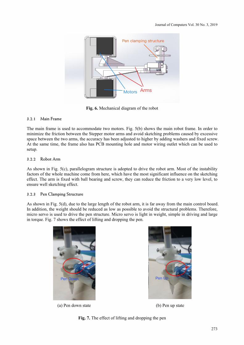
Fig. 6. Mechanical diagram of the robot
3.2.1 Main Frame
The main frame is used to accommodate two motors. Fig. 5(b) shows the main robot frame. In order to
minimize the friction between the Stepper motor arms and avoid sketching problems caused by excessive
space between the two arms, the accuracy has been adjusted to higher by adding washers and fixed screw.
At the same time, the frame also has PCB mounting hole and motor wiring outlet which can be used to
setup.
3.2.2 Robot Arm
As shown in Fig. 5(c), parallelogram structure is adopted to drive the robot arm. Most of the instability
factors of the whole machine come from here, which have the most significant influence on the sketching
effect. The arm is fixed with ball bearing and screw, they can reduce the friction to a very low level, to
ensure well sketching effect.
3.2.3 Pen Clamping Structure
As shown in Fig. 5(d), due to the large length of the robot arm, it is far away from the main control board.
In addition, the weight should be reduced as low as possible to avoid the structural problems. Therefore,
micro servo is used to drive the pen structure. Micro servo is light in weight, simple in driving and large
in torque. Fig. 7 shows the effect of lifting and dropping the pen.
(a) Pen down state (b) Pen up state
Fig. 7. The effect of lifting and dropping the pen

A Portable Sketching Robot Based on Artificial Intelligence
274
3.3 The Calculation of Sketching Range
One important question to consider is whether the range of the sketching can fetch the required position
on paper. If the range of sketching is too small, the robot will have little practical value. The important
parameter that determines the drawing range is the range of the motor can rotate. In order to obtain the
rotation range of the robot arm, the maximum angle of collision of the arm and the body was calculated
as 52.07° shown in Fig. 8.
Fig. 8. Calculation results of the maximum Angle achievable by the arm (profile map)
In order to leave a surplus, we choose 45° for the 2 motors rotation Angle in the range of - 45°~225°. 4
robot arms of a length of 8CM was selected, and the coordinate transformation algorithm above was used
for simulation to traverse all accessible points. The simulation results from these conditions are as
follows. It can draw a semicircle with a radius of about 15CM.Up to 50% of a piece of standard A4
papers, can adapt certain sketching requirements. The diagram of sketching range is shown in Fig. 9.
Fig. 9. The range of the robot that can be sketched (CM)
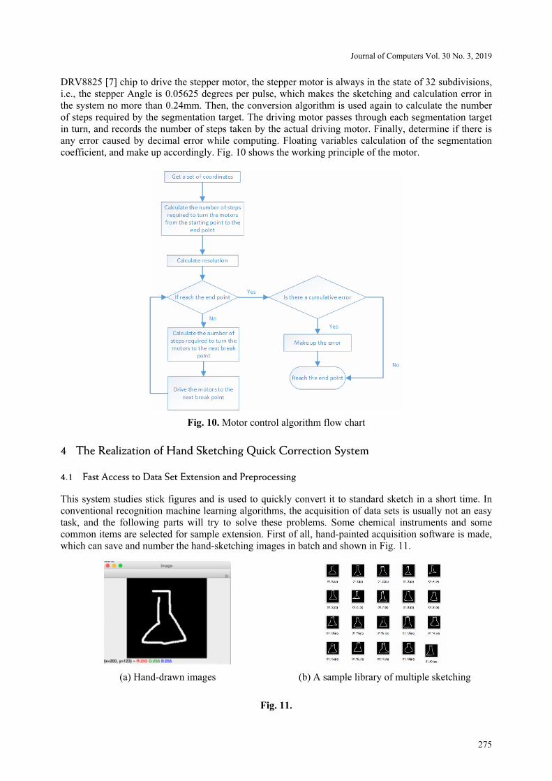
3.4 Motor Control Algorithm
After receiving the data from the upper computer, it is verified, converted and classified to obtain a set of
coordinate data. Then, the coordinate transformation algorithm is used to calculate the target angles of the
two motors required by the target coordinate, and then the step number of the stepper motor is converted
into the target step number. After that, the resolution of the segmentation coefficient is calculated by
taking the larger value of the total steps of the two motors. Enough segmentation is conducted for the
straight-line segment between the current point and the target point to ensure that the number of rotation
steps of each Stepper motor between each segmentation target is no more than two steps. Using the
Journal of Computers Vol. 30 No. 3, 2019
275
DRV8825 [7] chip to drive the stepper motor, the stepper motor is always in the state of 32 subdivisions,
i.e., the stepper Angle is 0.05625 degrees per pulse, which makes the sketching and calculation error in
the system no more than 0.24mm. Then, the conversion algorithm is used again to calculate the number
of steps required by the segmentation target. The driving motor passes through each segmentation target
in turn, and records the number of steps taken by the actual driving motor. Finally, determine if there is
any error caused by decimal error while computing. Floating variables calculation of the segmentation
coefficient, and make up accordingly. Fig. 10 shows the working principle of the motor.
Fig. 10. Motor control algorithm flow chart
4 The Realization of Hand Sketching Quick Correction System
4.1 Fast Access to Data Set Extension and Preprocessing
This system studies stick figures and is used to quickly convert it to standard sketch in a short time. In
conventional recognition machine learning algorithms, the acquisition of data sets is usually not an easy
task, and the following parts will try to solve these problems. Some chemical instruments and some
common items are selected for sample extension. First of all, hand-painted acquisition software is made,
which can save and number the hand-sketching images in batch and shown in Fig. 11.
(a) Hand-drawn images (b) A sample library of multiple sketching
Fig. 11.
A Portable Sketching Robot Based on Artificial Intelligence
276
It takes time to draw sketch in data set by hand, but the quantity is not simple to enough. Therefore, in
order to increase the number of training samples, improve the accuracy of identification and reduce the
workload, the sample sketches collected are randomly rotated and shifted. At the same time, in order to
prevent the storage of these sketches too large, reduce the calculating time, and reduce the size of the
pictures, the software extended each training sample into 100 different sketches, and then it will get 5000
sketches of each type shown in Fig. 12. Then reduce the size of image to 32x32.The sample still contains
most of the information on the original line, so it is suitable for training.
Fig. 12. Extension of an image produces multiple results
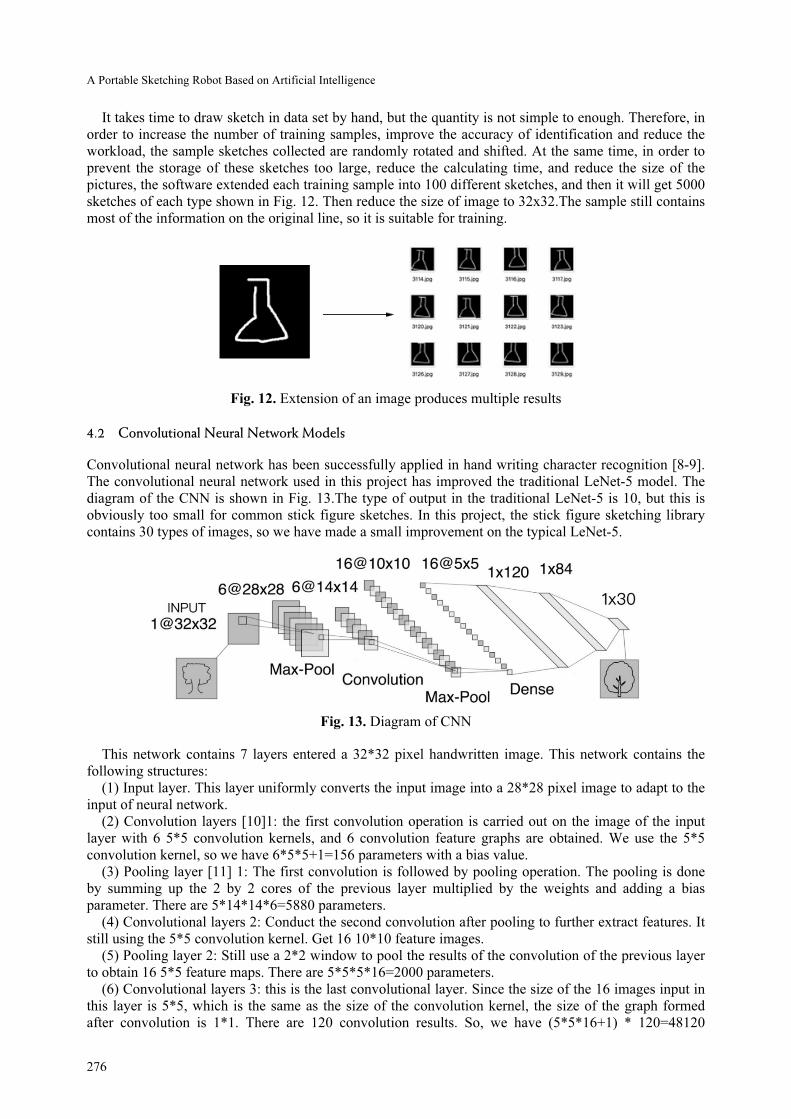
4.2 Convolutional Neural Network Models
Convolutional neural network has been successfully applied in hand writing character recognition [8-9].
The convolutional neural network used in this project has improved the traditional LeNet-5 model. The
diagram of the CNN is shown in Fig. 13.The type of output in the traditional LeNet-5 is 10, but this is
obviously too small for common stick figure sketches. In this project, the stick figure sketching library
contains 30 types of images, so we have made a small improvement on the typical LeNet-5.
Fig. 13. Diagram of CNN
This network contains 7 layers entered a 32*32 pixel handwritten image. This network contains the
following structures:
(1) Input layer. This layer uniformly converts the input image into a 28*28 pixel image to adapt to the
input of neural network.
(2) Convolution layers [10]1: the first convolution operation is carried out on the image of the input
layer with 6 5*5 convolution kernels, and 6 convolution feature graphs are obtained. We use the 5*5
convolution kernel, so we have 6*5*5+1=156 parameters with a bias value.
(3) Pooling layer [11] 1: The first convolution is followed by pooling operation. The pooling is done
by summing up the 2 by 2 cores of the previous layer multiplied by the weights and adding a bias
parameter. There are 5*14*14*6=5880 parameters.
(4) Convolutional layers 2: Conduct the second convolution after pooling to further extract features. It
still using the 5*5 convolution kernel. Get 16 10*10 feature images.
(5) Pooling layer 2: Still use a 2*2 window to pool the results of the convolution of the previous layer
to obtain 16 5*5 feature maps. There are 5*5*5*16=2000 parameters.
(6) Convolutional layers 3: this is the last convolutional layer. Since the size of the 16 images input in
this layer is 5*5, which is the same as the size of the convolution kernel, the size of the graph formed
after convolution is 1*1. There are 120 convolution results. So, we have (5*5*16+1) * 120=48120

Journal of Computers Vol. 30 No. 3, 2019
277
parameters.
(7) Full connection layer: There are 84 neural network nodes in this layer, corresponding to a binary
image of 7*12. The training parameters and the number of connections in this layer is (120 + 1) *
84=10164. The activation functions sigmoid is used to output the function. The network structure of this
layer is shown in the Fig. 14. The sigmoid function are shown as 4.2.1:
Fig. 14. Network structure of 7th layer
1
( )1 x
sigmod xe−
=
+ (4.2.1)
8. Output layer, which is also a fully connected layer, has 40 nodes and is composed of radial basis
function (RBF). Each neuron in the Output layer corresponds to a stick figure sketching category. The
calculation method of output y of RBF unit is shown in equation 4.2.2:
2( )
i j j ijy x w= Σ − (4.2.2)
LeNet-5 is a kind of neural network model that is very suitable for simple stick figure sketches. It can
efficiently use the information on images, and involves fewer parameters and consumes fewer system
resources. After the network structure is improved according to the number of stick figure sketches, it can
adapt to the recognition requirements of this project.
4.3 Samples Training and Its Results
This model runs in TensorFlow AI framework and converges the model with gradient descent algorithm.
The learning rate is 0.01, and the file name of the data set is the label of the file. In the training process,
90% of the pictures in the sample are taken as the training set, and 10% of the pictures are taken as the
test set. The pictures in the sample are randomly input for learning. The batch size of learning m = 90,
after training a batch of images,10 pictures were tested, and the test results of these 10 pictures was
recorded in the form of accuracy rate for effectiveness of statistical model.
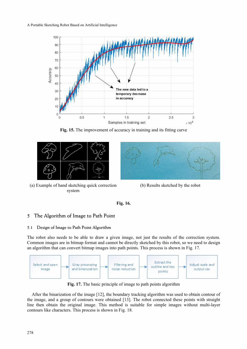
After the training, the result is output in the diagram. In the early, the accuracy rate is about 8% to 14%.
The accuracy of training has fluctuated, but the overall accuracy gradually increased, reaching about 95%
in the later. The learning process is shown in Fig. 15 and the result is shown in Fig. 16.
A Portable Sketching Robot Based on Artificial Intelligence
278
Fig. 15. The improvement of accuracy in training and its fitting curve
(a) Example of hand sketching quick correction
system
(b) Results sketched by the robot
Fig. 16.
5 The Algorithm of Image to Path Point
5.1 Design of Image to Path Point Algorithm
The robot also needs to be able to draw a given image, not just the results of the correction system.
Common images are in bitmap format and cannot be directly sketched by this robot, so we need to design
an algorithm that can convert bitmap images into path points. This process is shown in Fig. 17.
Fig. 17. The basic principle of image to path points algorithm
After the binarization of the image [12], the boundary tracking algorithm was used to obtain contour of
the image, and a group of contours were obtained [13]. The robot connected these points with straight
line then obtain the original image. This method is suitable for simple images without multi-layer
contours like characters. This process is shown in Fig. 18.

Journal of Computers Vol. 30 No. 3, 2019
279
(a) Original image (b) The original image and the extracted contour
(c) Result of connecting the contour points with
straight line
(d) The result of robot sketching
Fig. 18.
For the images with less obvious or more complex contour, we adopted the method of adding auxiliary
white line in the images, and then binarized the images and extracted the contour to obtain the complex
sketches drawn by the lines. The process is shown in Fig. 19. The closer the auxiliary lines are, the closer
the result is to the original, but the longer of the sketching time.
(a) Original image (b) Binary and add an
auxiliary white line to the
image
(c) Contour extraction of
the image
(d) The results of robot
sketching
Fig. 19.
5.2 Image Size Adaptive Algorithm
Since the input images are of different sizes, the image coordinates should be converted into the range of
coordinates that can be reached by the robot before the extraction of the image coordinates. Firstly, we
divide the coordinates into the left side of the picture and the right side of the picture. On the left side of
the screen, the horizontal axis is negative and the rest is positive. Consider the robot arm’s length d =
8CM, motor rotating Angle ranges from -45° to 225°, this program will map output point can be reached
to all areas. Therefore, each time a new coordinate is converted, it is only necessary to judge whether the
point belongs to the program, and then it can be judged whether the point is beyond the range of the
sketching area, and the coordinate can be adjusted in proportion to the sketching area to the appropriate
position. The formula of position adjustment is as follows:

A Portable Sketching Robot Based on Artificial Intelligence
280
2 2
1
2 2
1 1
( ) 2( 256 ) 16
256 16
x
y
cing xx x x x
cing
y x x x
×⎧= − − − −⎪
⎨⎪
= − − −⎩
(4.2-1)
Where, x and y are the length or width of the image; xnew and ynew are the adaptive coordinate positions;
i [0] and i [1] is the coordinate positions of the original image. Fig. 20 shows the result of this algorithm.
Fig. 20. Result of the image sizes adaptive algorithm
1
1
2 ( [0] )2
[1]
new
new
xx x i
y y i
⎧= −⎪
⎨⎪ = ×⎩
(4.2-2)
6 Conclusion
A portable tabletop sketching robot is designed by using the parallelogram mechanical structure which
occupies a small volume, and adapted a set of images to path point algorithm. At the same time, the
convolutional neural network is used to realize a sketching correction system. With this robot, people
with low sketching foundation can draw beautiful images quickly. It is convenient for study and life and
has the following advantages:
(1) the sketching robot using parallelogram structure, and improved the traditional sketching robot
which has large volume, high power consumption, and high manufacturing costs, the sketching robot
using this structure, make the volume, power consumption and cost is greatly reduced, at the same time,
it still be able to keep large sketching area, improved the traditional sketching robot’s largest problem.
(2) Designed a pen clamping structure integrated with the clamping structure on the robot arm, which
makes sketching pen more flexible without occupying too much volume. This is one of the most difficult
problems in volume reduction.
(3) A hand sketching correction system based on convolutional neural network is designed with
LeNet-5 neural network, which occupies less system resources, is used to recognize hand-painted images
in real time. After sketching, the hand-painted images can be immediately converted into corresponding
images which are more standard and can be drawn by the robot.
(4) An image-path conversion algorithm is proposed, which can process images with different
complexity and convert them into paths that can be drawn by robots.
(5) For images of different sizes, adaption algorithm is carried out according to the sketching area, so
that all of them can be normally drawn, and the problem of image beyond the sketching area is avoided.
The final product is shown in the Fig. 21. This sketching robot can be used for daily auxiliary
sketching. It is a kind of small equipment with short production cycle and low manufacturing cost, which
can meet different scenes. Equipment miniaturization is an effective way to develop science and
technology, which can make more scientific and technological equipment convenient for production and
daily life

Journal of Computers Vol. 30 No. 3, 2019
281
(a) Interface of the upper computer (b) the finished product
Fig. 21.
Acknowledgements
This work is supported by Talent Training Quality Improvement Foundation of Beijing Information Science &
Technology University (No. 5101924100)
References
[1] S. Sugano, Hito ga mita yume robotto no kita michi, Jeiaipi ̄emusoryu ̄shon, Tokyo, 2011.
[2] V.M Kumar, D.S.H. Thipesh, Robot arm performing writing through speech recognition using dynamic time warping
algorithm, International Journal of Engineering, Transactions B: Applications 30(8)(2017) 1238-1245.
[3] D. Song, T. Lee, Y.J. Kim, Artistic pen drawing on an arbitrary surface using an impedance-controlled robot, in: Proc. IEEE
International Conference on Robotics and Automation (ICRA), 2018.
[4] F.A. Raheem, H.Z. Khaleel, M.K. Kashan, Robot arm design for children writing ability enhancement using Cartesian
equations based on ANFIS, in: Proc. Third Scientific Conference of Electrical Engineering (SCEE), 2018.
[5] P. Atoofi, F.H. Hamker, J. Nassour, Learning of central pattern generator coordination in robot drawing, Front Neurorobot
(2018). doi: 10.3389/fnbot.2018.00044.
[6] K. Fernandez, Writing robot, [dissertation] Malaysia: University Tenaga Nasional, 2002..
[7] Texas Instruments, DRV8825 Stepper Motor Controller IC, SLVSA73F datasheet, April 2010.
[8] S.A. Sajjad, F. Razzazi, M.H. Ghassemian, A very high accuracy handwritten character recognition system for Farsi/Arabic
digits using Convolutional Neural Networks, in: Proc. 2010 IEEE Fifth International Conference on Bio-Inspired
Computing, 2010.
[9] Y. Lecun, L. Bottou, Y. Bengio, P. Haffner, Gradient-based learning applied to document recognition, Proceedings of the
IEEE 86(11)(1998) 2278-2324.
[10] F. Lauer, C.Y. Suen, G. Bloch, A trainable feature extractor for handwritten digit recognition, Pattern Recognition
40(6)(2007) 1816-1824.
[11] R. Moore, J. Denero, L1 and L2 regularization for multiclass hinge loss models, in: Proc. Symposium on Machine Learning
and Dynamical Systems, 2011.
[12] N. Otsu, A threshold selection method from gray-level histograms, IEEE Transactions on Systems, Man and Cybernetics
9(1)(1979) 62-66.
[13] S. Suzuki, K. Abe, Topological structural analysis of digitized binary images by border following, in: Proc. Computer
Vision, Graphics, and Image Processing, 1985