A Pipelined FFT Architecture for Real-Valued...
11
A Pipelined FFT Architecture for Real-Valued Signals Mario Garrido, Keshab. K. Parhi and Jesus Grajal Journal Article N.B.: When citing this work, cite the original article. ©2016 IEEE. Personal use of this material is permitted. However, permission to reprint/republish this material for advertising or promotional purposes or for creating new collective works for resale or redistribution to servers or lists, or to reuse any copyrighted component of this work in other works must be obtained from the IEEE. Mario Garrido, Keshab. K. Parhi and Jesus Grajal, A Pipelined FFT Architecture for Real- Valued Signals, IEEE Transactions on Circuits and Systems Part 1, 2009. 56(12), pp.2634- 2643. http://dx.doi.org/10.1109/TCSI.2009.2017125 Postprint available at: Linköping University Electronic Press http://urn.kb.se/resolve?urn=urn:nbn:se:liu:diva-70361
Transcript of A Pipelined FFT Architecture for Real-Valued...

A Pipelined FFT Architecture for Real-Valued Signals
Mario Garrido, Keshab. K. Parhi and Jesus Grajal
Journal Article
N.B.: When citing this work, cite the original article.
©2016 IEEE. Personal use of this material is permitted. However, permission to reprint/republish this material for advertising or promotional purposes or for creating new collective works for resale or redistribution to servers or lists, or to reuse any copyrighted component of this work in other works must be obtained from the IEEE.
Mario Garrido, Keshab. K. Parhi and Jesus Grajal, A Pipelined FFT Architecture for Real-Valued Signals, IEEE Transactions on Circuits and Systems Part 1, 2009. 56(12), pp.2634-2643. http://dx.doi.org/10.1109/TCSI.2009.2017125 Postprint available at: Linköping University Electronic Press
http://urn.kb.se/resolve?urn=urn:nbn:se:liu:diva-70361

IEEE TRANSACTIONS ON CIRCUITS AND SYSTEMS PART I: REGULAR PAPERS 1
A Pipelined FFT Architecture for Real-ValuedSignals
Mario Garrido, Keshab. K. Parhi, Fellow, IEEE, and J. Grajal
Abstract—This paper presents a new pipelined hardwarearchitecture for the computation of the real-valued fast Fouriertransform (RFFT). The proposed architecture takes advantageof the reduced number of operations of the RFFT with respectto the complex fast Fourier transform (CFFT), and requires lessarea while achieving higher throughput and lower latency.
The architecture is based on a novel algorithm for the com-putation of the RFFT, which, contrary to previous approaches,presents a regular geometry suitable for the implementationof hardware structures. Moreover, the algorithm can be usedfor both the Decimation In Time (DIT) and Decimation InFrequency (DIF) decompositions of the RFFT and requires thelowest number of operations reported for radix 2.
Finally, as in previous works, when calculating the RFFT theoutput samples are obtained in a different order. The problem ofreordering these samples is solved in this paper and a pipelinedcircuit that performs this reordering is proposed.
Index Terms—Fast Fourier Transform (FFT), Real-ValuedSignals, Pipelined Architecture, Reordering Circuit, Decimation-in-Time, Decimation-in-Frequency, Memory Reduction
I. INTRODUCTION
THE fast Fourier transform (FFT) is one of the mostimportant algorithms in the field of digital signal process-
ing, used to efficiently compute the discrete Fourier transform(DFT). For the computation of the FFT, pipelined hardwarearchitectures [1]-[9] are widely used because they offer highthroughput and low latency as well as a reasonably low areaand power consumption. This makes them attractive for a largevariety of applications, specially when they present real-timerequirements. Thus, in order to provide solutions to presentand future applications, hardware designers keep improvingthe signal processing capabilities of pipelined architectures ofthe FFT.
The FFT internally operates over complex numbers andprevious works offer efficient designs for the computation ofthe FFT of complex input samples (CFFT). However, they arenot optimized for the computation of the FFT of real inputsamples (RFFT). Indeed, when the input samples are real thespectrum of the FFT is symmetric [10] and approximately halfof the operations are redundant [11].
The RFFT plays an important role in different real-timeapplications. In medical applications such as ECG (Electro-cardiography) [12] or EEG (Electroencephalography) [13], thepower spectral density (PSD) of various real-valued signals
Mario Garrido and J. Grajal are with the Department of Signal, Systemsand Radiocommunications, Unversidad Politecnica de Madrid, 28040 Madrid,Spain, e-mails: [email protected], [email protected]
Keshab K. Parhi is with the Department of Electrical and ComputerEngineering, University of Minnesota, Minneapolis, MN 55455, USA, e-mail:[email protected]
has to be estimated. This requires calculation of the RFFTrepetitively on many overlapping windows of the signals,where a specialized hardware implementation can make use ofa higher speed clock to meet real-time constraints. Moreover,in implantable or portable devices [12], [13], a dedicatedhardware can save power consumption. On the other hand,the RFFT is a key element in technologies based on DMT(discrete multitone) modulation, such as ADSL (AsymetricDigital Subscriber Line) or VDSL (Very high bit-rate DigitalSubscriber Line) [14], [15]. Nowadays, high signal process-ing capabilities are required for second-generation standards(ADSL2/2+ [16] and VDSL2 [17]). Moreover, DMT has beenused at rates of 24 Gb/s in local area networks (LAN) [18].Finally, very high performance is also necessary in digitalwideband receivers [19], [20]. Currently, the RFFT has to becomputed in real time over a dataflow of 2 GSamples/s [20].
Thus, in order to meet the increasing demand on real-time capabilities of new applications, much research has beencarried out on pipelined architectures of the CFFT. On theother hand, for those applications with real input signals, adedicated pipelined RFFT architecture can lead to savingsin area and power consumption, while offering high signalprocessing capabilities. However, to the best of our knowledgeno hardware-efficient pipelined architecture for the computa-tion of the RFFT based on the Cooley-Tukey algorithm [21]has been proposed yet. There exist only some pipelinedarchitectures [22], [23] based on the Bruun algorithm [24].However, the Bruun algorithm has not been widely adoptedsince it was demonstrated [25] that the noise is significantlyhigher than that in the Cooley-Tukey algorithm [21].
The lack of specific pipelined architectures for the RFFTis due to the fact that the specific algorithms proposed forthe computation of the RFFT [11], [26]-[30], do not leadto regular geometries, which are necessary for designingpipelined architectures. These specific approaches describeprograms based on removing the redundancies of the CFFTwhen the input is real, and can be used to efficiently computethe RFFT in a DSP (Digital Signal Processor) or in in-placearchitectures [31]. A memory-based or in-place architectureconsists of a memory and a processing unit. The data areloaded, processed and stored again in the memory until allthe operations of the algorithms are performed. This kindof architecture allows the design of circuits with low areaand power consumption, but it is not suitable for real-timeapplications.
There exist other techniques described in [32], [33], whichtake advantage of the CFFT to calculate the RFFT. On onehand, the doubling algorithm uses the CFFT to compute

IEEE TRANSACTIONS ON CIRCUITS AND SYSTEMS PART I: REGULAR PAPERS 2
two RFFTs simultaneously. On the other hand, the packingalgorithm forms a complex sequence of length N/2 takingthe even and odd indexed samples of the real input sequenceof length N , and calculates the N/2-point CFFT of thecomplex sequence. In these CFFT-based techniques, additionaloperations are necessary to obtain the final results from theoutputs of the CFFT. The packing algorithm has been usedto implement some in-place architectures [15], [34]. In thesearchitectures the hardware of the CFFT can be reused forcomputing the post-processing stage. However, no pipelinedarchitecture has been proposed, not only because some of theadders and multipliers saved in the CFFT need to be usedfor post-processing, but mainly because the samples need tobe reordered before the post-processing stage [15], increasingthe memory and complicating the control.
Both in the specific algorithms for the computation of theRFFT and in the CFFT-based ones, the output samples areprovided in different orders [27], which are different from thebit-reversal one of the CFFT [35]. The sorting of the outputs ofthe RFFT is also a problem not solved in the literature so far.
In this work we propose the first pipelined architecturefor the computation of the RFFT based on the Cooley-Tukey algorithm. It combines the advantages of the pipelinedarchitectures with the reduction of operations achieved bythe specific algorithms. This is possible due to the proposedalgorithm for the computation of the RFFT which solves theirregularities of the RFFT. Moreover, this approach is valid forboth Decimation In Time (DIT) and Decimation In Frequency(DIF) decompositions and is generalizable for any number ofpoints N , which is power of 2. Furthermore, the problem ofthe output order of the samples is solved and a pipelined circuitthat performs the reordering is proposed.
In the next section we briefly review the RFFT and theexisting techniques to compute it. In Section III we developthe algorithm that allows the design of regular hardwarearchitectures for the computation of the RFFT, and the novelproposed pipelined architecture is presented Section IV. Next,in Section V the architecture is evaluated and compared toprevious approaches, and some conclusions are drawn inSection VI. Finally, the reordering of the output samples andthe proposed solution are discussed in Appendix A.
II. THE RFFTThe N -point DFT of a sequence x[n] is defined as:
X[k] =
N−1∑n=0
x [n] WnkN , k = 0, 1, . . . , N − 1 (1)
where WnkN = e−j
2πN nk.
The RFFT considers the input sequence, x[n], to be a realsequence, i.e., ∀n, x[n] ∈ R. It is easy to demonstrate [10]that if x[n] is real, then the output X[N − k] is complexconjugate of X[k]. Consequently, an RFFT can be considereda conventional FFT with the additional conditions:
Im(x[n]) = 0 (2)
andX[N − k] = X∗[k] (3)
These two conditions that distinguish the CFFT and theRFFT do not lead, however, to a direct simplification ofequation (1) for the RFFT, and the specific algorithms for thecomputation of the RFFT require complicated developments.Thus, other simpler techniques that use the CFFT to computethe RFFT are sometimes preferred. Next, these approaches arereviewed.
A. Computation of the RFFT using the CFFT
1) Direct use of the CFFT: The first idea when it isnecessary to compute an FFT over a real input signal isto use the CFFT. As the real numbers are a subset of thecomplex ones, the trivial solution is to set the imaginary partof the input to zero. Although this procedure does not makean efficient use of the resources, it is very simple and it isnot necessary to modify the CFFT. Indeed, it is the solutionadopted for many if not all real-time applications.
2) Doubling Algorithm: Another alternative is to takeadvantage of the CFFT to simultaneously compute the FFTof two real signals x1[n] and x2[n], n = 0, 1, . . . , N − 1as it is explained in [32], [33]. This process requires toform the signal y[n] = x1[n] + j · x2[n] and use an N-pointCFFT to obtain Y [k] = X1[k] + j · X2[k]. It is importantto notice that both X1[k] and X2[k] are complex, so theycannot be obtained directly from Y [k]. Therefore, 2(N − 1)additions are required to separate the outputs, in addition tothe operations of the CFFT.
3) Packing Algorithm: Given a real signal x[m], m =0, 1, . . . ,M −1 it is also possible to compute the RFFT usingan M/2-point CFFT [32], [33]. This technique is sometimescalled packing algorithm because it takes the odd and evenindexed samples of the signal and form the complex signaly[n] = x[2n] + j · x[2n + 1], n = 0, 1, . . . , N − 1 andN = M/2. Then the N -point CFFT is applied to obtainY [k], k = 0, 1, . . . , N − 1. As in the doubling algorithm,2(N − 1) additions are required to separate the outputs ofthe CFFT. Moreover, in the packing algorithm it is necessaryto include an additional stage to compute the outputs of theRFFT, which requires 4N − 1 extra additions and 4(N − 1)multiplications.
B. Specific Algorithms for the Computation of the RFFT
The greater reduction in the number of operations is ob-tained by using the specific algorithms for the computationof the RFFT. Most of them are obtained from the CFFT byapplying the properties of the RFFT in order to remove theredundant operations. The first proposed algorithms were de-fined for the DIT (Decimation In Time) decomposition of theFFT. The DIT FFT has the property that the samples at eachintermediate stage can be computed using the conventionalFFT [10]. Consequently, equation (3) can be applied at eachstage, and only one half of the intermediate outputs must becalculated, whereas the rest can be obtained by conjugatingthose intermediate values.

IEEE TRANSACTIONS ON CIRCUITS AND SYSTEMS PART I: REGULAR PAPERS 3
This is the basic idea of algorithms proposed for split-radix [11], [26], radix-2 [27], [30] and high radices [28]. Thesealgorithms are, however, not valid for the DIF (DecimationIn Frequency) decomposition of the FFT because it is notpossible to apply the property (3) at each stage. On the otherhand, it has been also demonstrated that it is possible toobtain the same savings for the DIF decomposition usingan alternative algorithm [29] that makes use of linear-phasesequences.
In general, the number of multiplications in all of thesealgorithms is reduced to half of that required for the CFFT,and the number of additions is N − 2 less than half theadditions of the CFFT. Likewise, only half of the memoryis needed. Thus, there are only slight differences among all ofthem in the number of operations and in the order in whichthe computations are performed.
III. PROPOSED ALGORITHM FOR THE COMPUTATION OFTHE RFFT
A. Basis of the algorithm
Figure 1 shows the flow graph of an N -point FFT for thecase of N = 16, radix r = 2, and decomposed according tothe decimation in frequency (DIF) [10]. The graph is dividedinto logrN = 4 stages and each of them consists of a setof butterflies and rotators. The numbers at the input and theoutput of the graph represent respectively the index of the inputand output samples, whereas each number, φ, in between thestages indicates a rotation by:
e−j2πN φ (4)
If we consider that the inputs are complex, all the internalnodes and outputs of the graph are needed for the computationof the CFFT, and the regularity of the flow graph leads toefficient pipelined architectures [2]. On the other hand, if theinputs are real, it is possible to simplify the graph accordingto the properties of the RFFT, as explained next.
1.- The first simplification is to consider that in the realFFT X[N − k] = X∗[k]. According to this, N/2 − 1outputs of the FFT are redundant and can be removed. Mostapproaches [11], [27], [31] obtain either the frequencies withindexes k = [0, N/2] or k = [0, N/4] ∪ [N/2, 3N/4] and, ifnecessary, calculate the rest of the frequencies by conjugatingthese results. However, considering that k′ = N/4− k− 1 forthe indices k, k′ = 0, . . . , N/4− 1 and using the property (3):
X[4k + 3] = X∗[N − 4k − 3] = X∗[4k′ + 1] (5)
leads to a more efficient architecture.Consequently, the set of frequencies X[4k + 3] can be
obtained by conjugating frequencies X[4k+ 1], as mentionedin [26] for the split-radix RFFT. According to Figure 1,samples X[4k+3] are the last quarter of the outputs; so all thebutterflies used exclusively to compute these samples may beremoved, which are represented by the lower darkened region.
The same concept can be applied to samples X[8k + 6],which can be computed by conjugating samples X[8k + 2].Generalizing this idea, samples X[2α · (4k + 3)] can becomputed by conjugating the samples X[2α · (4k+ 1)], where
Fig. 1. Flow graph of a 16-point DIF FFT. The darkened regions and theboxed components are considered in the simplifications of the new algorithmfor the RFFT.
k = 0, . . . , N/(4 ·2α)−1, for all α = 0, . . . , log2N−2. Thus,all the darkened regions in Figure 1 can be removed and onlyN/2− 1 outputs of the FFT need to be computed.
2.- The second simplification refers to the fact thatIm(x [n]) = 0. According to this, every piece of data is realuntil it is rotated for the first time. In Figure 1, all the additionsperformed before the data reach the boxed components are realand, thus, the number of additions in that area is halved withrespect to the CFFT. Once the data reach the first rotations,the data are necessarily complex until the end of the FFT.
3.- One further simplification of the boxed components maybe carried out. Let’s assume that the first stage of the FFTis s = 1 and the last one is s = n ≡ logrN , and Xs
are the outputs of stage s. According to this and Figure 1,in the second stage it is not necessary to compute the dataX2[i + 3N/4], i = 0, . . . , N/4−1, and samples X2[i+N/2]are calculated as:
X2[i+N/2] = X1[i+N/2] · e−j 2πN i+
+X1[i+ 3N/4] · e−j 2πN (i+N/4) (6)
This calculation requires 2 rotations and 1 addition. How-ever, expanding the expression and taking into account thatboth X1[i+N/2] and X1[i+ 3N/4] are real samples, we canobtain:
X2[i+N/2] = {X1[i+N/2]− j ·X1[i+ 3N/4]} · e−j 2πN i
(7)The resulting expression only requires one rotation and no
additions because X1[i+N/2] and X1[i+ 3N/4] are real androtations by 1,−1, j and−j are trivial, taking into account thatthey can be calculated by interchanging the real and imaginary

IEEE TRANSACTIONS ON CIRCUITS AND SYSTEMS PART I: REGULAR PAPERS 4
Fig. 2. Simplified flow graph of a 16-point FFT for real input samples,before a regular structure is obtained.
parts and/or changing the sign of the data. This simplificationcan be extended to all the boxed components, which reduceseven more the number of rotators and adders of the FFT.
Figure 2 represents the flow graph of the RFFT oncethe explained simplifications have been carried out. All thedata previous to the boxed components are real, and onlyreal butterflies are necessary for this region. On the otherhand, according to equation (7) the boxed components donot require any operation but the trivial rotation −j, sincethe additions that appear in the graph do not have to beperformed because one of the inputs is real and the other oneis purely imaginary. Finally, the complex rotations appear afterthe boxed components and the butterflies need to be complex.Consequently, it is easy to see from Figure 2 that the totalnumber of real additions is N log2N−(N−2) or, consideringthat n = log2N :
# add = (n− 1) · 2n + 2 (8)
Likewise, the number of non-trivial complex multiplicationscan be obtained from the flow graph as:
# mult = (n− 4) · 2n−2 + n (9)
With regard to the output samples, all the frequenciesX[0] to X[N/2] can be computed from the obtained data byconjugating those frequencies with index greater than N/2.
The explained simplifications can also be applied to theDIT FFT. In this case it is first necessary to redraw the typicalflow graph of the DIT FFT so that the inputs are in naturalorder and the outputs in bit-reversal [36]. The result onlydiffers from that of Figure 2 in the rotations performed atthe different stages. In this case, the number of non-trivialcomplex multiplications can be calculated as:
Fig. 3. Proposed flow graph of a 16-point DIF RFFT. All edges are real andthe boxed numbers represent rotations of the RFFT according to equation (4).The sign of the data is changed in edges where −1 is depicted.
Fig. 4. Proposed flow graph of a 16-point DIT RFFT. All edges are real andthe boxed numbers represent rotations of the RFFT according to equation (4).The sign of the data is changed in edges where −1 is depicted.
# mult = (n− 3) · 2n−2 + 1 (10)
Finally, as in the other specific designs of RFFT, theobtained structures are irregular because the symmetries ofthe CFFT have been used to reduce the number of opera-tions. Although the flow graph in Figure 2 could be used toimplement an in-place architecture, it is not suitable for theimplementation of a pipelined architecture.
B. Obtaining regularity
The last step of the algorithm consists of transforming theflow graph in Figure 2 to obtain a flow graph with regulargeometry. The obtained structure is depicted in Figure 3 forthe DIF FFT, whereas the result for the DIT decomposition is
IEEE TRANSACTIONS ON CIRCUITS AND SYSTEMS PART I: REGULAR PAPERS 5
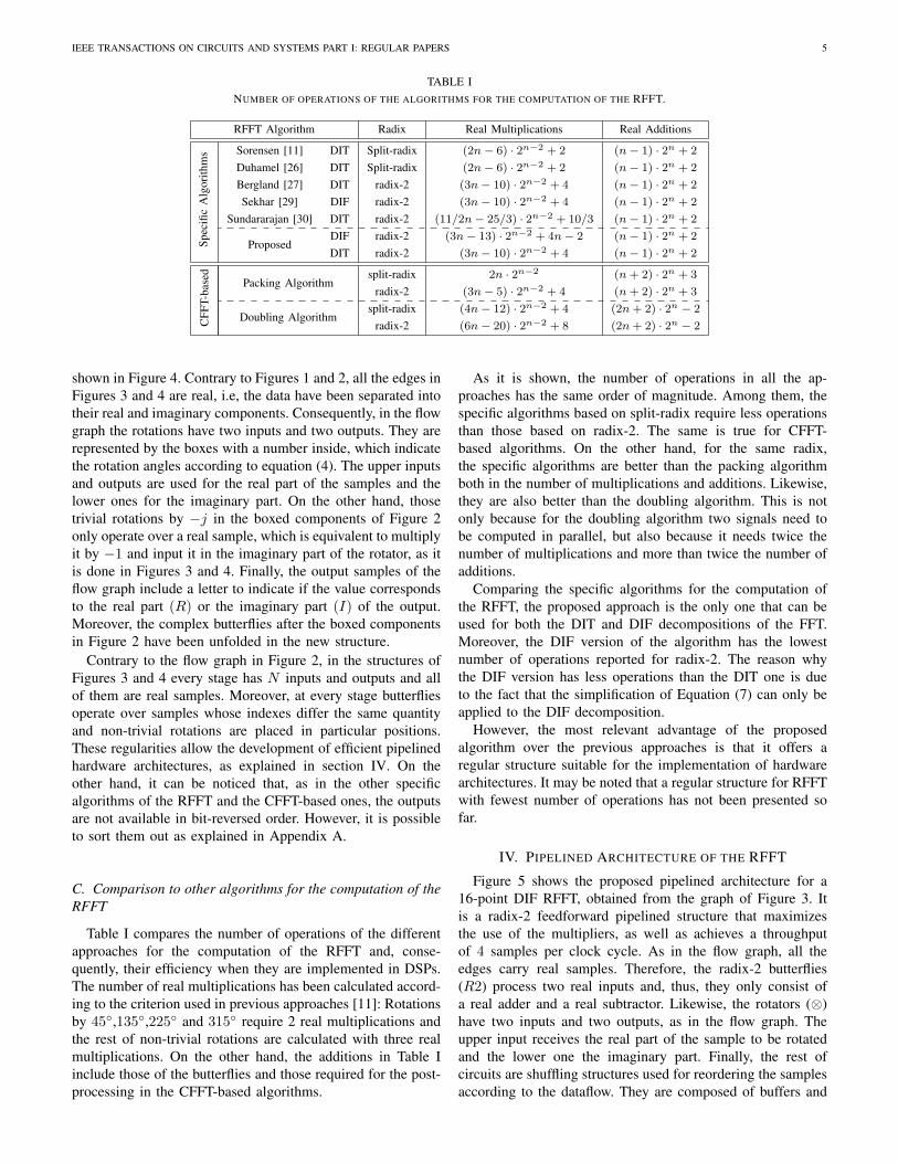
TABLE INUMBER OF OPERATIONS OF THE ALGORITHMS FOR THE COMPUTATION OF THE RFFT.
RFFT Algorithm Radix Real Multiplications Real Additions
Spec
ific
Alg
orith
ms Sorensen [11] DIT Split-radix (2n− 6) · 2n−2 + 2 (n− 1) · 2n + 2
Duhamel [26] DIT Split-radix (2n− 6) · 2n−2 + 2 (n− 1) · 2n + 2
Bergland [27] DIT radix-2 (3n− 10) · 2n−2 + 4 (n− 1) · 2n + 2
Sekhar [29] DIF radix-2 (3n− 10) · 2n−2 + 4 (n− 1) · 2n + 2
Sundararajan [30] DIT radix-2 (11/2n− 25/3) · 2n−2 + 10/3 (n− 1) · 2n + 2
ProposedDIF radix-2 (3n− 13) · 2n−2 + 4n− 2 (n− 1) · 2n + 2
DIT radix-2 (3n− 10) · 2n−2 + 4 (n− 1) · 2n + 2
CFF
T-ba
sed
Packing Algorithmsplit-radix 2n · 2n−2 (n+ 2) · 2n + 3
radix-2 (3n− 5) · 2n−2 + 4 (n+ 2) · 2n + 3
Doubling Algorithmsplit-radix (4n− 12) · 2n−2 + 4 (2n+ 2) · 2n − 2
radix-2 (6n− 20) · 2n−2 + 8 (2n+ 2) · 2n − 2
shown in Figure 4. Contrary to Figures 1 and 2, all the edges inFigures 3 and 4 are real, i.e, the data have been separated intotheir real and imaginary components. Consequently, in the flowgraph the rotations have two inputs and two outputs. They arerepresented by the boxes with a number inside, which indicatethe rotation angles according to equation (4). The upper inputsand outputs are used for the real part of the samples and thelower ones for the imaginary part. On the other hand, thosetrivial rotations by −j in the boxed components of Figure 2only operate over a real sample, which is equivalent to multiplyit by −1 and input it in the imaginary part of the rotator, as itis done in Figures 3 and 4. Finally, the output samples of theflow graph include a letter to indicate if the value correspondsto the real part (R) or the imaginary part (I) of the output.Moreover, the complex butterflies after the boxed componentsin Figure 2 have been unfolded in the new structure.
Contrary to the flow graph in Figure 2, in the structures ofFigures 3 and 4 every stage has N inputs and outputs and allof them are real samples. Moreover, at every stage butterfliesoperate over samples whose indexes differ the same quantityand non-trivial rotations are placed in particular positions.These regularities allow the development of efficient pipelinedhardware architectures, as explained in section IV. On theother hand, it can be noticed that, as in the other specificalgorithms of the RFFT and the CFFT-based ones, the outputsare not available in bit-reversed order. However, it is possibleto sort them out as explained in Appendix A.
C. Comparison to other algorithms for the computation of theRFFT
Table I compares the number of operations of the differentapproaches for the computation of the RFFT and, conse-quently, their efficiency when they are implemented in DSPs.The number of real multiplications has been calculated accord-ing to the criterion used in previous approaches [11]: Rotationsby 45◦,135◦,225◦ and 315◦ require 2 real multiplications andthe rest of non-trivial rotations are calculated with three realmultiplications. On the other hand, the additions in Table Iinclude those of the butterflies and those required for the post-processing in the CFFT-based algorithms.
As it is shown, the number of operations in all the ap-proaches has the same order of magnitude. Among them, thespecific algorithms based on split-radix require less operationsthan those based on radix-2. The same is true for CFFT-based algorithms. On the other hand, for the same radix,the specific algorithms are better than the packing algorithmboth in the number of multiplications and additions. Likewise,they are also better than the doubling algorithm. This is notonly because for the doubling algorithm two signals need tobe computed in parallel, but also because it needs twice thenumber of multiplications and more than twice the number ofadditions.
Comparing the specific algorithms for the computation ofthe RFFT, the proposed approach is the only one that can beused for both the DIT and DIF decompositions of the FFT.Moreover, the DIF version of the algorithm has the lowestnumber of operations reported for radix-2. The reason whythe DIF version has less operations than the DIT one is dueto the fact that the simplification of Equation (7) can only beapplied to the DIF decomposition.
However, the most relevant advantage of the proposedalgorithm over the previous approaches is that it offers aregular structure suitable for the implementation of hardwarearchitectures. It may be noted that a regular structure for RFFTwith fewest number of operations has not been presented sofar.
IV. PIPELINED ARCHITECTURE OF THE RFFT
Figure 5 shows the proposed pipelined architecture for a16-point DIF RFFT, obtained from the graph of Figure 3. Itis a radix-2 feedforward pipelined structure that maximizesthe use of the multipliers, as well as achieves a throughputof 4 samples per clock cycle. As in the flow graph, all theedges carry real samples. Therefore, the radix-2 butterflies(R2) process two real inputs and, thus, they only consist ofa real adder and a real subtractor. Likewise, the rotators (⊗)have two inputs and two outputs, as in the flow graph. Theupper input receives the real part of the sample to be rotatedand the lower one the imaginary part. Finally, the rest ofcircuits are shuffling structures used for reordering the samplesaccording to the dataflow. They are composed of buffers and

IEEE TRANSACTIONS ON CIRCUITS AND SYSTEMS PART I: REGULAR PAPERS 6
Fig. 5. Proposed pipelined architecture for the computation of the 16-point DIF RFFT. The architecture is composed of radix-2 real butterflies (R2),rotators (⊗), and shuffling structures, which include buffers and multiplexors.
Fig. 6. Shuffling structure of the pipelined RFFT. This examples shows theshuffling of the second stage of a 16-point RFFT.
multiplexors. In a general case of an N -point RFFT, with Npower of two, the circuit requires 2·log2(N)−1 real butterflies,log2(N)− 2 rotators, and buffers or memories of a total sizeN − 4.
Considering both Figures 3 and 5, the first stage computesonly real butterflies. According to the input order of the data,the upper butterfly of the structure computes the pairs ofsamples (0, 8), (1, 9), (2, 10) and (3, 11), whereas the lowerbutterfly operates samples (4, 12), (5, 13), (6, 14) and (7, 15).
On the other hand, both in the architecture and in the flowgraph, the upper outputs of the butterflies of the first stage areconnected to a butterfly of the second stage, whereas the loweroutputs are rotated in the second one. Previous to the rotator,it is necessary to compute a trivial rotation of −1, which canbe embedded in the rotator.
At the second stage, the butterflies operate over each pair ofsamples X1[i] and X1[i+N/4], and the rotations are calculatedover X1[i + N/2] and X1[i + 3N/4], for i = 0, . . . , 3.Consequently, the indexes of two samples operated togetheralways differ by N/4. On the other hand, at the third stage,the indexes of two samples operated together differ by N/8.
According to this, the shuffling structure depicted in Fig-ure 6, which corresponds to the second stage of the architec-
ture of Figure 5, shows how the order of the data required atthe second stage of the 16-point RFFT is transformed to theorder of the third stage. The structure consists of buffers andmultiplexors. In the Figure, the length of the buffers is L = 2,and the numbers of the inputs and the outputs represent theindex of each piece of data. Thus, the structure receives inparallel samples from the second stage, whose indexes differby N/4 = 4, and provides in parallel samples adapted to thethird stage, where the indexes differ by N/8 = 2.
The shuffling is performed in two steps. The first oneinterchanges the intermediate inputs and the second step in-terleaves the data. Considering the upper circuit of the secondstep, indexed samples (0, 1, 2, 3) and (8, 9, 10, 11) are receivedrespectively at each of the inputs. Initially the control of themultiplexors is set to ”0” and, thus, samples with indexes (0, 1)are stored in the output buffer and (8, 9) in the input one. Next,the control signal switches to ”1” and indexed samples (0, 1)are provided at the output in parallel with (2, 3), whereas (8, 9)pass to the output buffer and (10, 11) are stored in the inputone. These samples will be provided in parallel at the outputwhen the multiplexor switches again to ”0”.
In a general case of an N -point RFFT, the shuffling structureat a stage s ∈ [2, n−1] requires buffers of length L = N/2s+1,and, as can be observed in Figure 5, for the first stage of theRFFT, s = 1, only the first step of the shuffling structure isrequired.
On the other hand, the third stage of the architecture inFigure 5 includes a switch before the rotator. This switch isnecessary in every stage s ∈ [3, n − 1]. As it is shown inFigure 3 the rotations required by the boxed components ofFigure 1 operate over samples whose indexes differ the samequantity as the butterflies at the same stage. For these rotations,the switch does not swap the inputs. However, for the rest ofrotations the switch is activated and the samples that comefrom the lower output of the upper butterfly are routed throughthe rotator.
Finally, Figure 7 represents the hardware architecture for theDIT RFFT. It only differs from the DIF structure in Figure 5on the placement of the boxed switch and the rotator, due tothe fact that the positions of the rotations in the flow graphsof Figures 3 and 4 are different.

IEEE TRANSACTIONS ON CIRCUITS AND SYSTEMS PART I: REGULAR PAPERS 7
Fig. 7. Proposed pipelined architecture for the computation of the 16-point DIT RFFT. The architecture is composed of radix-2 real butterflies (R2),rotators (⊗), and shuffling structures, which include buffers and multiplexors.
TABLE IICOMPARISON OF PIPELINED HARDWARE ARCHITECTURES FOR THE COMPUTATION OF AN N-POINT RFFT.
AREA PERFORMANCEPIPELINED Complex Complex Complex Memory Latency Throughput
ARCHITECTURE Rotators Adders Samples Rotations (cycles) (samples/cycle)FB Radix 2, [1] log4N − 1 2(log4N) 4N/3 N N 1FB Radix 2, [2] 2(log4N − 1) 4(log4N) N N N 1
FB Radix 4, [2], [3] log4N − 1 8(log4N) N N N 1FB Radix 22, [2] log4N − 1 4(log4N) N N N 1FB Split-radix, [4] log4N − 1 4(log4N) N N N 1
FF Radix 2, [5] 2(log4N − 1) 2(log4N) N N N 1FF Radix 2, [2] 2(log4N − 1) 4(log4N) N N N/2 2FF Radix 2, [3] 2(log4N − 1) 4(log4N) 4N N N 2FF Radix 2, [6] 2(log4N − 1) 4(log4N) N N N/2 2FF Radix 4, [7] log4N − 1 3(log4N) 2N N N 1FF Radix 4, [8] 3(log4N − 1) 8(log4N) N N N/4 4FF Radix 4, [3] 3(log4N − 1) 8(log4N) 8N/3 N N/3 4FF Radix 4, [6] 3(log4N − 1) 8(log4N) N N N/3 4
Proposed 2(log4N − 1) 4(log4N) N/2 3N/4 N/4 4
V. COMPARISON AND ANALYSIS
Table II compares the proposed structure to other efficientpipelined architectures for the case of computing an N -pointRFFT. The proposed design is the only specific approach forthe computation of the RFFT and, thus, it takes advantage ofthe reduced number of operations required by the RFFT withrespect to the CFFT. The other approaches are not specific forthe RFFT and can be used to calculate the CFFT.
The table shows the trade off between area and performance.The area is measured in terms of the number of complex rota-tors, adders and memory addresses, whereas the performanceis represented by the throughput and the latency. In all cases,the throughput is that for which each architecture has beendesigned, and the number of components and the latency aremeasured from the butterflies of the first stage to those ofthe last stage, i.e, circuits for reordering the input and outputsamples have not been considered. This criterion shows thelowest area and the highest performance that each architecturecan obtain. As it can be observed in the table, feedback (FB)architectures and some feedforward (FF) ones [5], [7] requireless hardware components and achieve a throughput of onesample per clock cycle. On the other hand, the parallelizationof feedforward architectures has the advantage of a higherthroughput and a lower latency due to an increase in area.
The proposed architecture is in the group of the feedforwardones. It uses radix-2 but can process 4 samples in parallel,
achieving a higher performance than feedback designs, both interms of latency and throughput. On the other hand, comparedto other radix-2 feedforward architectures, the proposed designdoubles the throughput and halves the latency and the datamemory, while keeping the same number of rotators andadders. Therefore, although the new approach uses radix-2, itachieves the same throughput as other radix-4 feedforward ar-chitectures. Compared to these high-throughput architectures,the proposed one obtains a significant reduction in the numberof rotators, adders and memory addresses.
The reduction in memory is an important advantage of theproposed architecture. It only needs a total of N real memoryaddresses for the samples or, equivalently, N/2 complex ones.This involves a great reduction in area, taking into accountthat, except in case of computing a low number of samples, thememory takes up most of the area of the circuit. Moreover, thememory used to store the coefficients for the rotations has beenreduced to 3N/4. Thus, the low area makes the architecturevery suitable for the implementation of long-length transforms.
Finally, it is interesting to analyze the case that inputsamples arrive in natural order. Under these circumstancesfeedforward architectures require input memories for reorder-ing the samples, whereas feedback structures do not needany additional hardware. For the proposed design it can beused a memory of N real samples or, equivalently, N/2complex samples. As the throughput of the architecture is
IEEE TRANSACTIONS ON CIRCUITS AND SYSTEMS PART I: REGULAR PAPERS 8
4 samples per clock cycle, the memory will be filled inN/4 cycles, leading to a total latency of the circuit of N/2cycles. Consequently, using the same memory as a feedbackarchitecture, the proposed design can process 4 times moresamples in half the time.
As a conclusion, the high performance and the low area ofthe new architecture make it very attractive for the computationof the RFFT in real-time applications.
VI. CONCLUSION
The previous approaches on the RFFT had demonstratedthat it requires half the operations of the CFFT. This papershows that this reduction of operations is not only theoreticalbut also can be applied to the design of efficient hardwarearchitectures for the computation of the RFFT. This is possibledue to the novel algorithm proposed in this paper for thecomputation of the RFFT, which obtains a regular geometrysimilar to that of the CFFT, and is valid for both the DIF andDIT decompositions of the RFFT. Based on this algorithm, anew pipelined architecture for the computation of the RFFTis presented. It processes 4 samples in parallel and requiressignificantly less memory than other efficient pipelined struc-tures. The low area and latency, and the high throughput ofthe circuit make it attractive for the computation of the FFTin any application that processes real samples. Moreover, thecircuit is very efficient for long-length transforms due to thereduction in memory, and it is also very suitable for real-timeapplications because of its high throughput capabilities.
APPENDIX AREORDERING OF THE OUTPUT SAMPLES
The scrambled order of the output samples is an inherentproblem of the FFT. In the CFFT the outputs are obtained inthe so called bit-reversal order [35]. In in-place architectures itis possible to reuse the memory to sort out the output samples,which increases the latency and reduces the throughput of thesystem.
On the other hand, in pipelined architectures an extramemory of N addresses is necessary to perform the bit-reversal, which increases the area and the latency. Samplesare stored in the memory in natural order using a counterfor the addresses and then they are read in bit-reversal byreversing the bits of the counter. Moreover, it is possible touse this strategy for calculating the bit-reversal of a series ofFFTs. In this case, the first FFT is stored in natural order.Next, the count is in bit-reversal and, thus, the frequencies areprovided in the correct order, while the outputs of the secondFFT are stored in the memory in bit-reversal order. Since thebit-reversal is an inversion operation, i.e, Br(x) = Br−1(x),the outputs of the second FFT must be read in natural orderto sort out the frequencies. At the same time, the third FFT isstored in natural order, which completes the cycle.
Nevertheless, for reordering the outputs of the RFFT amore complicated algorithm is required. Next the algorithm isexplained to be performed in-place and then it is shown thatit is possible to perform it in pipeline and the correspondingcircuit is presented.
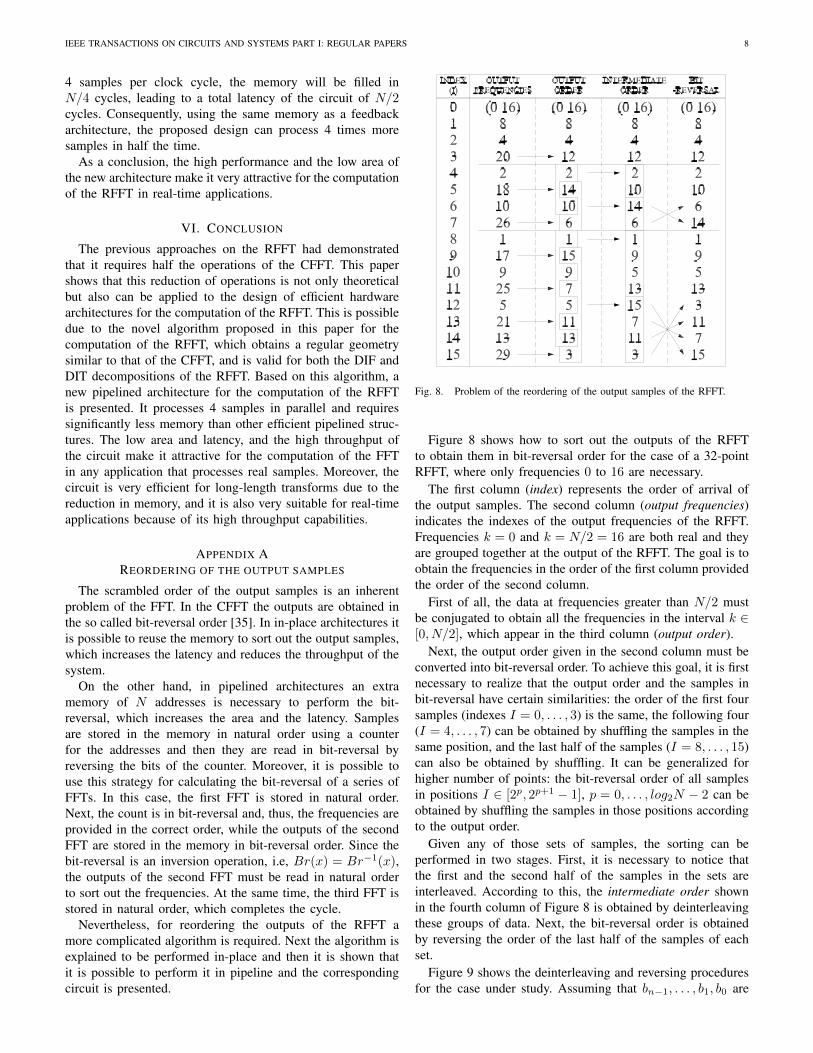
Fig. 8. Problem of the reordering of the output samples of the RFFT.
Figure 8 shows how to sort out the outputs of the RFFTto obtain them in bit-reversal order for the case of a 32-pointRFFT, where only frequencies 0 to 16 are necessary.
The first column (index) represents the order of arrival ofthe output samples. The second column (output frequencies)indicates the indexes of the output frequencies of the RFFT.Frequencies k = 0 and k = N/2 = 16 are both real and theyare grouped together at the output of the RFFT. The goal is toobtain the frequencies in the order of the first column providedthe order of the second column.
First of all, the data at frequencies greater than N/2 mustbe conjugated to obtain all the frequencies in the interval k ∈[0, N/2], which appear in the third column (output order).
Next, the output order given in the second column must beconverted into bit-reversal order. To achieve this goal, it is firstnecessary to realize that the output order and the samples inbit-reversal have certain similarities: the order of the first foursamples (indexes I = 0, . . . , 3) is the same, the following four(I = 4, . . . , 7) can be obtained by shuffling the samples in thesame position, and the last half of the samples (I = 8, . . . , 15)can also be obtained by shuffling. It can be generalized forhigher number of points: the bit-reversal order of all samplesin positions I ∈ [2p, 2p+1 − 1], p = 0, . . . , log2N − 2 can beobtained by shuffling the samples in those positions accordingto the output order.
Given any of those sets of samples, the sorting can beperformed in two stages. First, it is necessary to notice thatthe first and the second half of the samples in the sets areinterleaved. According to this, the intermediate order shownin the fourth column of Figure 8 is obtained by deinterleavingthese groups of data. Next, the bit-reversal order is obtainedby reversing the order of the last half of the samples of eachset.
Figure 9 shows the deinterleaving and reversing proceduresfor the case under study. Assuming that bn−1, . . . , b1, b0 are

IEEE TRANSACTIONS ON CIRCUITS AND SYSTEMS PART I: REGULAR PAPERS 9
Fig. 9. Solution to the reordering of the output samples of the RFFT.
the bits of the index I , the deinterleaving moves a sample inposition P = bn−1, bn−2, . . . , bp, bp−1, . . . , b1, b0 to positionP ′ = bn−1, bn−2, . . . , bp, b0, bp−1, . . . , b2, b1, where p =blog2(P )c. This is performed by successively interchangingthe bits bα, bα+1 from α = 0 to α = p− 2. Note that in thisfigure p = 2 for I ∈ [4, 7] and p = 3 for I ∈ [8, 15], so eachgroup of samples is treated differently.
On the other hand, the reversing moves the data in positionsP = bn−1, bn−2, . . . , bp, 1, bp−2, . . . , b1, b0 to position P ′ =bn−1, bn−2, . . . , bp, 1, bp−2, . . . , b1, b0. The reversing can beperformed by negating the position bit by bit and interchangingthe corresponding data.
Fig. 10. Basic circuit for the reordering of the output data.
This procedure can be easily performed in place, but it isalso possible to implement a pipelined hardware structure forthe reordering of the samples. It is necessary to realize that ev-ery stage of the deinterleaving and the reversing interchangessamples in positions P and P ′ = P+L, where L is a constant.The simple circuit in Figure 10 performs this exchange. If themultiplexer is set to ”1” the samples will be provided at theoutput in the same order as in the input, whereas setting it to”0” the input sample in position P ′ is forwarded to positionP , while the data in position P is fed back to the buffer andwill appear at the output in position P ′.
Fig. 11. Structure for the reordering of the output data of a 32-point RFFT.
Joining the stages of the deinterleaving and the reversing,the circuit in Figure 11 performs the reorder of the outputs to
obtain them in bit-reversed order. As it can be seen, it onlyuses six complex registers for a 32-point RFFT. In a generalcase, a N -point RFFT requires buffers or a memory of 2 ·(N/8− 1) complex data to obtain the outputs in bit-reversal,and a memory of N/2 complex data to obtain them in naturalorder.
REFERENCES
[1] L. Yang, K. Zhang, H. Liu, J. Huang, and S. Huang. ’An efficient locallypipelined FFT processor’. IEEE Transactions on Circuits and SystemsII: Express Briefs, 53(7):585–589, July 2006.
[2] S. He and M. Torkelson. ’Design and implementation of a 1024-pointpipeline FFT processor’. Custom Integrated Circuits Conference, SantaClara, CA, pages 131–134, May 1998.
[3] M. A. Sanchez, M. Garrido, M. L. Lopez, and J. Grajal. ’Implementingthe FFT Algorithm on FPGA Platforms: A Comparative Study of ParallelArchitectures’. XIX International Conference on Design of Circuits andIntegrated Sistems (DCSI 2004), (Bourdeaux, France), November 2004.
[4] Wen-Chang Yeh and Chein-Wei Jen. ’High-speed and low-power split-radix FFT’. IEEE Transactions on Signal Processing, 51(3):864–874,March 2003.
[5] Y.-N. Chang. ’An Efficient VLSI Architecture for Normal I/O OrderPipeline FFT Design’. IEEE Transactions on Circuits and Systems II:Express Briefs, 55(12):1234–1238, December 2008.
[6] Chao Cheng and Keshab K. Parhi. ’High-Throughput VLSI Architecturefor FFT Computation’. IEEE Transactions on Circuits and Systems II:Express Briefs, 54(10):863–867, October 2007.
[7] G. Bi and E.V. Jones. ’A pipelined FFT processor for world-sequentialdata’. IEEE Transactions on Acoustics, Speech and Signal Processing,37(12):1982–1985, December 1989.
[8] E.E. Swartzlander, W.K.W. Young, and S.J. Joseph. ’A radix 4 delaycommutator for fast Fourier transform processor implementation’. IEEEJournal of Solid-State Circuits, 19(5):702–709, October 1984.
[9] Y.-W. Lin and C.-Y. Lee. ’Design of an FFT/IFFT Processor for MIMOOFDM Systems’. IEEE Transactions on Circuits and Systems I: RegularPapers, 54(4):807–815, April 2007.
[10] A.V.Oppenheim and R.W.Schafer. Discrete-Time Signal Processing.Prentice Hall, 1989.
[11] H.V. Sorensen, D.L. Jones, M.T. Heideman, and C.S. Burrus. ’Real-valued fast Fourier transform algorithms’. IEEE Transactions onAcoustics, Speech and Signal Processing, 35:849–863, June 1987.
[12] M.-H. Cheng, L.-C. Chen, Y.-C. Hung, and C.M. Yang. ’A real-timemaximum-likelihood heart-rate estimator for wearable textile sensors’.Engineering in Medicine and Biology Society, 2008. EMBS 2008. 30thAnnual International Conference of the IEEE, pages 254–257, August2008.
[13] R.F. Yazicioglu, P. Merken, R. Puers, and C. Van Hoof. ’Low-PowerLow-Noise 8-Channel EEG Front-End ASIC for Ambulatory Acqui-sition Systems’. European Solid-State Circuits Conference, ESSCIRC2006, pages 247–250, 2006.
[14] O.W. Ibraheem and N.N. Khamiss. ’Design and Simulation of Asym-metric Digital Subscriber Line (ADSL) Modem’. ICTTA 2008, pages1–6, April 2008.
[15] Hsiang-Feng Chi and Zhao-Hong Lai. ’A cost-effective memory-basedreal-valued FFT and Hermitian symmetric IFFT processor for DMT-based wire-line transmission systems’. IEEE International Symposiumon Circuits and Systems, 6:6006–6009, May 2005.
[16] ITU-T Recommendation G.992.5: Asymmetric Digital Subscriber Line(ADSL) transceivers Extended bandwidth ADSL2 (ADSL2plus). 2005.
[17] ITU-T Recommendation G.993.2: Very high speed digital subscriberline transceivers 2 (VDSL2). 2006.
[18] S.C.J. Lee et al. ’24-Gb/s Transmission over 730 m of Multimode Fiberby Direct Modulation of an 850-nm VCSEL using Discrete Multi-toneModulation’. https://w3.tue.nl/fileadmin/ele/TTE/ECO/Files/Pubs 2007/Lee PDP6 OFC 07.pdf, 2007.
[19] G. Lopez-Risueno, J. Grajal, and A. Sanz-Osorio. ’Digital channelizedreceiver based on time-frequency analysis for signal interception’. IEEETransactions on Aerospace and Electronic Systems, 41(3):879–898, July2005.
[20] Y.-H.G. Lee and C.-I.H. Chen. ’Dual Thresholding for Digital Wide-band Receivers with Variable Truncation Scheme’. IEEE InternationalSymposium on Circuits and Systems, ISCAS, May 2009.
[21] J.W. Cooley and J.W. Tukey. ’An algorithm for the machine calculationof complex Fourier series’. Math. Comput., 19:297–301, 1965.

IEEE TRANSACTIONS ON CIRCUITS AND SYSTEMS PART I: REGULAR PAPERS 10
[22] R. Storn. ’A novel radix-2 pipeline architecture for the computationof the DFT’. IEEE International Symposium on Circuits and Systems,2:1899–1902, June 1988.
[23] Y. Wu. ’New FFT structures based on the Bruun algorithm’. IEEETransactions on Acoustics, Speech and Signal Processing, 38(1):188–191, January 1990.
[24] G. Bruun. ’z-Transform DFT filters and FFT’s’. IEEE Transactions onAcoustics, Speech and Signal Processing, 26(1):56–63, February 1978.
[25] R. Storn. ’Some results in fixed point error analysis of the Bruun-FTTalgorithm’. IEEE Transactions on Signal Processing, 41(7):2371–2375,July 1993.
[26] P. Duhamel. ’Implementation of Split-radix FFT algorithms for complex,real, and real-symmetric data’. IEEE Transactions on Acoustics, Speechand Signal Processing, 34(2):285–295, April 1986.
[27] G.D. Bergland. ’A Fast Fourier Transform Algorithm for real-valuedSeries’. Commun. ACM, 11(10):703–710, October 1968.
[28] G.D. Bergland. ’A Radix-eight Fast Fourier Transform subroutine forreal-valued Series’. IEEE Trans. on Audio and Electroacoustics, AU-17(2):138–144, June 1969.
[29] B.R. Sekhar and K.M.M. Prabhu. ’Radix-2 decimation-in-frequency al-gorithm for the computation of the real-valued FFT’. IEEE Transactionson Signal Processing, 47(4):1181–1184, April 1999.
[30] D. Sundararajan, M.O. Ahmad, and M.N.S. Swamy. ’Some resultsin fixed point error analysis of the Bruun-FTT algorithm’. IEEETransactions on Signal Processing, 41(7):2371–2375, July 1997.
[31] J.A. Hidalgo-Lopez, J.C. Tejero, J. Fernandez, E.Herruzo, and A. Gago.’New architecture for RFFT calculation’. Electronics Letters,30(22):1836–1838, October 1994.
[32] E. Oran Brigham. The fast Fourier transform and its applications.Prentice Hall, 1988.
[33] Winthrop W. Smith and Joanne M. Smith. Handbook of Real-Time FastFourier Transforms. Wiley-IEEE Press, 1995.
[34] A. Wang and A.P. Chandrakasan. ’Energy-aware Architectures for aReal-valued FFT Implementation’. International Symposium on LowPower Electronics and Design, pages 360–365, August 2003.
[35] Lawrence R. Rabiner and Bernard Gold. Theory and Application ofDigital Signal Processing. Prentice Hall, 1975.
[36] Mario Garrido Galvez. ’Desarrollo de algoritmos para deteccion desenales en tiempo real mediante FPGAs’. ETSI de Telecomunicacion,UPM, December 2004.
Mario Garrido received his M.S. degree in Elec-trical Engineering from the Technical University ofMadrid (UPM), Madrid, Spain, in December 2004.He is currently working towards the Ph.D degree inthe Department of Signals, Systems and Radiocom-munications, UPM.
His research interests include the design and opti-mization of VLSI architectures for signal processingapplications.
Keshab K. Parhi (S’85-M’88-SM’91-F’96) re-ceived his B.Tech., MSEE, and Ph.D. degrees fromthe Indian Institute of Technology, Kharagpur, theUniversity of Pennsylvania, Philadelphia, and theUniversity of California at Berkeley, in 1982, 1984,and 1988, respectively. He has been with the Univer-sity of Minnesota, Minneapolis, since 1988, wherehe is currently Distinguished McKnight UniversityProfessor in the Department of Electrical and Com-puter Engineering.
His research addresses VLSI architecture designand implementation of physical layer aspects of broadband communicationssystems, error control coders and cryptography architectures, high-speedtransceivers, and ultra wideband systems. He is also currently working onintelligent classification of biomedical signals and images, for applicationssuch as seizure prediction, lung sound analysis, and diabetic retinopathyscreening. He has published over 450 papers, has authored the text book VLSIDigital Signal Processing Systems (Wiley, 1999) and coedited the referencebook Digital Signal Processing for Multimedia Systems (Marcel Dekker,1999).
Dr. Parhi is the recipient of numerous awards including the 2004 F.E.Terman award by the American Society of Engineering Education, the 2003IEEE Kiyo Tomiyasu Technical Field Award, the 2001 IEEE W.R.G. Bakerprize paper award, and a Golden Jubilee award from the IEEE Circuitsand Systems Society in 1999. He has served on the editorial boards of theIEEE TRANSACTIONS ON CAS, CAS-II, VLSI Systems, Signal Processing,Signal Processing Letters, and Signal Processing Magazine, and served as theEditor-in-Chief of the IEEE Trans. on Circuits and Systems - I (2004-2005term), and currently serves on the Editorial Board of the Journal of VLSISignal Processing. He has served as technical program cochair of the 1995IEEE VLSI Signal Processing workshop and the 1996 ASAP conference,and as the general chair of the 2002 IEEE Workshop on Signal ProcessingSystems. He was a distinguished lecturer for the IEEE Circuits and Systemssociety during 1996-1998. He was an elected member of the Board ofGovernors of the IEEE Circuits and Systems society from 2005 to 2007.
J. Grajal was born in Toral de los Guzmanes (Len),Spain, in 1967. He received his M.S and Ph.D. inElectrical Engineering degrees from the TechnicalUniversity of Madrid (UPM), Madrid, Spain, in 1992and 1998, respectively. Since 2001 he has been anAssociate Professor at the Department of Signals,Systems, and Radiocommunications of the TechnicalSchool of Telecommunication Engineering of thesame University.
His research activities are in the area of hardware-design for radar systems, radar signal processing and
broadband digital receivers for radar and spectrum surveillance applications.