
Control of phytoplankton production by physical forcing in a strongly ...
Upload
trinhduongCategory
view
233download
2
17 (2008) 691–704www.elsevier.com/locate/autcon
Automation in Construction
A physical design grammar: A production system for layeredmanufacturing machines
Lawrence Sass
Department of Architecture, Massachusetts Institute of Technology, United States
Accepted 17 December 2007
Abstract
This paper addresses the need to generate functionally large geometries/objects for layered manufacturing machines. Novelty is found in thetranslation from an initial shape in CAD to subdivision as interlocking objects that are further subdivided into slicing layers using traditionallayered manufacturing software. Translation from an initial shape to individual component geometry is guided by shape rules as a set grammar thatgenerate a 2D drawing of interlocking shapes. Mechanical rules further shape the 3D geometry of each object, resulting in a virtual model thatcomplies with measures of structural stability, assembly, and machine manufacturing. Three models are constructed to illustrate the translationprocess from the virtual shape to a manufactured artifact.© 2007 Elsevier B.V. All rights reserved.
Keywords: Rapid prototyping; Shape grammars; Integral attachment; Production system
1. Introduction
1.1. Production systems
For architects, design production is both a visual and aphysical process that produces text, drawings, and models thatserve to confirm assumptions, design decisions, and changes. Inspite of the many advances in CAD and fabrication technologiesformal, professional sets of drawings and their accompanyingtext specifications are the commonplace final design represen-tation. With the increasing use of computer modeling and rapidprototyping machines, however, it has become necessary toreevaluate the methods of design production. Benefits of newmethods of computer modeling directed for fabrication arefaster concept to construction processes for architects andgreater access to construction principles for novice and expertdesigners. Most important is that new modeling methods di-rected at fabrication can allow for full scale physical construc-tion with little more than a computer and a CNC machine.
In computer science, the initial production systems resultedin computer programs for artificial intelligence that managed
E-mail address: [email protected].
0926-5805/$ - see front matter © 2007 Elsevier B.V. All rights reserved.doi:10.1016/j.autcon.2007.12.003
symbolic information as input controlled by conditional state-ments [1]. These systems produced text-based outcomes. At thesame time, shape grammar design was being explored as analternative production system that managed shapes with con-ditional statements related to spatial relationships, with out-comes in the form of drawings [2].
This paper considers systematic design production forarchitects who are interested in layered manufacturing devices(rapid prototyping). This system can also generate data forfabrication with larger CNC devices for clarity rapid prototyp-ing is the focus of this paper. The system illustrated heresupports creative design with highly visual, highly physicaloutcomes. Fortunately, layered manufacturing can facilitateboth visual and physical evaluation, as confirmed by research-ers and professionals alike [3–9]. This process generates stack-able blocks or objects that summarize to parts of a design. Bestfor architects is that the models that are materialized withlayered manufacturing permit an increased understanding ofform and space. A common method employed to build blocks ofthis type is mold making for concrete building components. Thelimitations are in the molds and the number of mold variation.More molds leads to an increase in price and manufacturingtime. Layered manufacturing does not always work with molds,

Fig. 1. Very large rapid prototype models of a skyscraper built in two scales ondisplay in London.
692 L. Sass / Automation in Construction 17 (2008) 691–704
parts can be manufactured with little difference in price or timein manufacturing.
However, it is also true that the outcomes produced bylayered manufacturing are limited by factors associated with themachine tool (e.g., machine size), materials, and physicalbehaviors—issues that become clear post model production.These factors make changes in design modeling complex andcan necessitate significant amounts of time to accommodateeven the smallest alteration. For example, changing the virtualmodel that was used to manufacture the physical model in Fig. 1from its current description as a curved building to a flat-sidedbuilding might require days of work time. Unless the virtualmodel was predetermined for parametric transformations, such
Fig. 2. Descriptions for conventional layered manufacturing (a) and a proposed descripslicing software (b).
as curved components that transform to straight components, anew model is needed when overall geometric change is desired.An effective production system designed exclusively forlayered manufacturing can serve as part of a materializingsystem that allows for rapid change.
Design productions with traditional handheld model-makingtools (referred to as legacy model making) do not suffer thesame limitations. For one of a kind, sketchy model makingwhere detailing and intricate form making is not importantlegacy modeling making can be very efficient. Knives, paperboard, small strips of wood, and glue enable designers to buildmodels quickly. A benefit of legacy model making is that anarchitect can physically reason through a design problem as partof the model-making experience, regardless of model size. Incontrast, legacy model making can be slow for repetitiouschanges. For example, manufacture of a set of models withslight variations between each model. Last, legacy methods arequite slow particularly when highly skilled model making isneeded for high-quality finished models. Layered manufactur-ing machines can facilitate high-quality model making, but theprocess requires many hours of the problem here is in the manyhours of upfront investment in virtual modeling [6–8].
1.2. Motivation
The shortcomings in design production with layered man-ufacturing software are limited in subdivision based on behaviorand making. This type of software translates a model intorepetitious layers of material with little regard for model be-havior, such as with structure or model balancing post man-ufacturing (Fig. 2a) or model size. A uniform set of layered
tion for layered manufacturing adding an initial grammar before processing with

Fig. 4. Freeform model manufactured as a single build model with a color 3Dprinter.
693L. Sass / Automation in Construction 17 (2008) 691–704
material is inefficient and does not scale in ranges from the verysmall to building size. Most machines are limited in themaximum size of model manufacture; the maximum length for acommon layered manufacturing device is less than 10 in.(25.8 cm) (Fig. 2a). Architects, however, would benefit from avariety of size models that can be manufactured from the samemachine with software functions that subdivide a model intoparts with attachments.
Architects need descriptions that work with a variety of sizemachines from the very small to larger layered manufacturingmachines, such as Contour Crafting [10]. This need for diverseoutcomes is best illustrated when an attempt is made to fabricate avariety of models, such as those in Fig. 1. Both models in Fig. 1were manufactured by laser sintering from the same or similarinitial virtual model. If a third model were to be the size of themodel in Fig. 5, on the other hand, remodeling would be required.It is not efficient for scaling a model intended for printing as asmall model to a very large model of the type in Fig. 5.
This research attempts to find an new description for layeredmanufacturing that can consider performance-based designfactors as well as visual ones. Here a secondary computation isproposed that subdivides a model (initial shape) into objects thatinclude an attachment strategy as part of the generative process.Also a method to shape objects based on structural loading andmechanical strategies. Calculation and generation of these objectswith features (such as attachments) occurs before the slicingalgorithms found in layered manufacturing software (Fig. 2b).
1.3. Physical production system
This paper introduces a production system as a schema thatspecifies information for materializing a design built of units.This system is defined as a physical design grammar used totransform a design model (surface model) into sets of scalabledescriptions for production by layered manufacturing. Thesedescriptions can be nonuniform models of the type shown inFig. 3; these object-based descriptions differ in geometric de-scription to satisfy most physical design constraints. In theory,the resulting geometry is scale-less; it can be used to build asmall model or the full-scale building. The maximum size ofeach object represented as b in Fig. 2b is limited by the machine
Fig. 3. 3D-printed working models as a collection of objects with compliantattachments.
size. The artifact itself, though, is limited in size by the numberof parts, not the maximum length of b, as illustrated in Fig. 2a.
This production system also considers automated translationfrom a surface to a series of objects. A grammar guides thegeneration of objects based on physical constraints. Objectsdefined in the materialization system are automatically assignedby rules in the grammar to key locations in space. Results arephysically compliant artifacts whose sum of objects can begreater in physical size than the maximum length of the machineenvelope. The grammar generates objects with attachmentfeatures for mating with adjacent objects, and the final model isassembled by hand (Fig. 3).
1.4. Research challenge
The challenge is to define and test a physical productionsystem that generates information for manufacturingmany designartifacts. This method contradicts many design traditions bystarting the design process with clearly defined components(objects). By contrast, most architectural problems begin with ill-defined abstract shape descriptions and end with new descriptions(building components) constrained for manufacturing andassembly. Here, the process starts with highly constrained objectgeometry as a scaffold for manufacturing defined design shapes.
Second, layered manufacturing is typically employed to buildconceptual models as single build objects similar to sculpturalartifacts (Figs. 4 and 5). In contrast, our physical productionsystem enables model manufacturing as collections of discreteobjects assembled by hand, defined as a working model (Fig. 3).
The research challenges with a physical production systemare:
• Can layered manufacturing be used to generate scalablecomponents/large artifacts?
• Can layered manufacturing be used to build working modelsthat express mechanical functions such as componentassembly or structure?
• Is it possible to integrate a physical formal system with avisual formal system?

Fig. 5. In the office of Kohn Pederson Fox, an architect points to a collection ofskyscrapers manufactured by 3D printing and stereolithography.
694 L. Sass / Automation in Construction 17 (2008) 691–704
1.5. Theoretical framework
This research is novel in considering layered manufacturingfor the production of highly visual artifacts built from acollection of interlocking objects (Fig. 3). The theoreticalframework for this paper combines three concepts found indesign and computing. First, we need to compute integral at-tachments (i.e., snap fit) like those typically found in the plasticsindustry as a system of physically interlocking objects [11].Next, we use shape grammar formalism, which offers a highlyvisual process and supports the mathematical rigor needed fortranslation of rules and descriptions to computer programminglanguages [12]. Last, although not explored in detail here, wecompute the mechanics of objects and assemblies [13]. Theexpectation is that integrating a visual grammar with a physicalgrammar will create a viable design production system thatworks across length scales. Examples of this concept are pre-sented as free-standing wall structures in the last three sectionsof this paper.
2. Background: design mediation with physical models
To understand the goal of a physical production system, it isimportant to understand both the purpose and the production ofarchitectural models. Architects throughout history have usedphysical models in design in their efforts to challenge funda-mental realities such as structure and function in addition totesting for style. To guide the transformation of conceptualsketches to real buildings, architects use mockups and models,which mediate physical decisions and help to resolve detailsbefore construction begins. These physical models inform theclient and collaborators of the architect's intent and offer thedesigner some autonomy and understanding of the physicalaspects of the design [14]. Morris provides a detailed expla-nation of current model-making culture for architects [15].
Two model types are discussed in this paper. The first type—a viewing model, also referred to as a finished model—may beused to mediate conflicts in design appearance [16,17].Michelangelo built finished models of St. Peter's Basilica in
Rome to explain the spatial layout and detail in his appearancewith Pope Paul III [18].
The second type—a working model—may be used to chal-lenge functional qualities of a design such as tiling patterns,component assembly, and general operable components. Work-ing models are not always finished in detail and may be built outof a variety of parts and even moving objects. Building aworking model is analogous to hand-drawn sketching in that themodel is never finished and can be rebuilt many times over untildesign issues are resolved.
In the 16th century, Alberti used wooden working models tostudy the relationship of the building to the site, or to calculatethe width, height, form, and appearance of a particular buildingelement. By reference to the initial fabricators' wooden models,Alberti and the fabricators were able to make improvementsusing new wooden models and Alberti's drawings. Sir JohnSloane also made clear use of working models for design andconstruction, noting that a correct model of the design and all itsparts should be built before construction can begin and that sucha great model would be useful to the workmen [19]. Gaudi usedplaster models to construct studies and optimize freeform struc-tural geometry for the masons to follow [20]. His workingmodels provided the designers and masons with materialmediation between building form and structure prior to full-scale fabrication. More recently, Burry illustrated the possibi-lities of CAD/CAM and rapid prototyping as an additional aidfor stone cutters working on the Sagradi Familia. Burry writesthat the traditions in handcraftedmodel making and stone cuttingprohibit the application of the computer and digital fabricationdevices. In his work, however, Burry used rapid prototyping as avisual tool for the stone cutters but inferred that it should be usedas a working tool, similar to Gaudi's approach [20].
This paper focuses on using working models as tools forfunctional mediation between the designer and the potentialfabricator. Functional models are geometrical reflections of thevirtual objects explored in this paper. Alternatively, workingmodels allow for physical discovery and learning related tomechanics and structure [21]. Working models reflect mechan-ical and structural learning in three dimensions and in time. thatis too complex for virtual modeling systems. Bill Phillips built ahydraulic model with water flow as an alternative way tounderstand financial flow in the English economy in the 1950s.His machine illustrates market changes in savings and spending,as well as investment and exports and tax flow. Prior to Phil-lips's machine, economic teaching was predominately non-mathematical and on the cusp between verbal and mathematicalmethods of study. His model satisfied a need for increasedunderstanding of the third and fourth dimensions of monetaryproblems [22]. Architects require functional models to teststandard and non-standard methods to construct buildings. Testsinclude assembly strategies for parts and innovative structuralstrategies. Testing of physical functions in design is becomingever more important now that most design projects aregenerated in virtual environments (CAD). Modern computerscan not calculate the many forces found in physical prototypingas an integrated model, physical prototyping is a necessarycomponent in the design process.

695L. Sass / Automation in Construction 17 (2008) 691–704
3. Descriptions
3.1. Low-level descriptions
This section illustrates a constructive approach towardgenerating effective descriptions for working models. Thesearch is for a scalable representation as modeled geometry forlayered manufacturing. The research here is analogous to theexploration in computer science in search of high-level pro-gramming languages above assembly coding [23]. For earlysoftware designers and programmers, low-level assembly codeswere difficult to work with. Often, programmers ended uprewriting basic functions with each new program. In the mid1960s, though, the development of higher level object-orientedprogramming languages provided programmers with librariesof predetermined code. Once the program was designed, com-piling software would transform groups of code from softwareobjects to lower level assembly language.
Generation of low level description is handled by rapidprototyping software. It works much like a compiler or trans-lator by slicing or reducing an initial shape or object into layers,referred to here as a low-level description (Fig. 2a). Each slicedescription is a vector file that drives a two-step machineprocess. The slicing software is defined in Fig. 2a as (I). First, athin layer of material is manufactured (defined as an objectbody) and placed atop a previously built layer. Hardware pro-cessing affixes the new layer to the previous layer as part of themanufacturing process. A benefit of this process is that eachlayer can differ in shape, provided there is a geometric asso-ciation with the previous layer. The hardware manages theassembly between layers via temperature-controlled fusion (for
Fig. 6. A single built model produced from a collection of laye
Fuse Deposition Modeling [FDM]), fusion by liquid binding(for 3D printing), or both [24].
3.2. High-level descriptions
Generation of a higher level description illustrated in Fig. 2bshows a process that integrates a physical grammar (I) (used togenerate higher level descriptions) and slicing software (II).Instead of considering each layer as an object body, a high-leveldescription considers a single build model first, and then asliced version. Each object body from the grammar is in-dividually manufactured and includes integrated assemblygeometry. With this approach, large parts can be generated,manufactured and assembled quickly. Large parts can also bescaled to many times their size and manufactured with the samedevice for full-scale building construction. For example, thefirst model in Fig. 6b shows a 25-cm box built of 24 objects (4per side) and a second box built of 96 objects (16 per side).Once assembled, both models are hollow with no internalstructure, which reduces the time- and material-consuming infillthat are found when printing a solid box with a low-leveldescription (Fig. 6a). Although complementary research existsconcerning layered manufacturing for building models of thinwall structures [25], this method involves infill material similarto the model in Fig. 6a.
3.3. Description for grammar
A grammar is introduced to support the automated genera-tion of higher level objects within the physical productionsystem. Similar to shape grammar design, the physical design
rs and working models built out of a collection of objects.

696 L. Sass / Automation in Construction 17 (2008) 691–704
grammar presented here generates high-level descriptions asscalable geometries for layered manufacturing across machinetypes. Shape grammars work with high-level descriptions bycomputing shapes and shape transformation, as opposed tolower level transformational rules found with text-based pro-duction systems [12]. The shape grammar rule format helpsorganize and compute designs with rules based on physicalfactors. A shape grammar contains a finite set of initial shapes(S) and labels (L), and a finite set of rules α→β that transform alabeled shape α into a labeled shape β. The research in thispaper also works with a finite set of initial objects and rules tocompute the object(s). This grammar is similar in nature to a setgrammar that is built of a finite set of components with fewopportunities for emergence. Because the grammar is based onfixed physical constraints emergence between object bodies isnot always desirable.
It should be noted that attempts to use rule transformationswith physically based functions are found in shape grammarliterature. Brown et al. explored shape grammar transformationswith rules constrained for a computer-controlled lathe [26].Shape and shape transformations are noted in the paper, but theresearch does not present physical evidence of grammar out-comes. A second example is a grammar that generates shapemodels from a list of shape relationships. Resulting modelswere manufactured with an FDM 3D printer, but the authorsspecified that manufacturing was not a part of the grammarconstruct [27]. In both cases, rule operations were a combina-tion of functions related to form, materials, or machinery.Missing from both of these examples, however, is a realisticintegration of shape-based physical function results.
4. Workflow
The complete workflow for this physical design grammar isoutlined in Fig. 7, starting with a solid model in CAD (I). Thisinitial shape is then subdivided into a grid determined by thedesigner (II). A physical design language is applied to translatethe grid into objects with attachments (III), which results inobjects that comply with many physical standards. For example,if a designers starting shape is a box, once the box is subdividedin virtual space it should stand up in physical space. The shapeof the box should comply with gravitational loading as well asmodel handling. These compliant objects are ready formanufacture as a collection of single build models or .stl files.
Fig. 7. Materializing process, starting with
This is followed by layered manufacturing and hand assemblyof objects (IV), (V). The final models in Fig. 7 (V) represent thegoals of this project, which are to build very large models as acollection of objects larger than the manufacturing device. Oncethe model is assembled, the physical artifact can stand over36 in. in height. Most important, with this type of workflow it ispossible for an architect to redesign in stage (I) quickly andmanufacture (II–V) a new artifact from a redefined initial shape.Depending on the type of new shape determined in the redesignmanufacture of new parts, in most cases the new artifact shouldcall for complete remanufacture of all parts.
5. Object design, computing, and mechanics
5.1. Design
There are two stages of implementation. The first is thedesign of a finite set of interlocking objects (O). These objectsare deemed compliant if they are designed for computing andcan connect firmly and withstand normal physical forces, suchas gravity, shear forces associated with model movement andhandling, and assembly forces when joining parts. The secondstage is a grammar design that is manifested as a set of finiterules and labeled objects (L) that guide the placement ofcompliant objects in correct positions from a starting grid; theserules are discussed in the next section.
The design of an object must include mechanisms thatcontrol connectivity and physical assembly so that a completeartifact can be built. The mechanical goals of the rules aretwofold: to support compliance in object attachment to matingobjects, and to ensure that the object will embody an overallstructure that resists gravity and provides object strength. Themechanical rules control tolerance between adjoining objects bycomputing object density with other rules that shape each objectto resist gravitational loads [13]. Mechanical rules also restrictthe size of any object for manufacture by limiting the maximumsize. Finally, mechanical rules ensure that each object is notbuilt of more material than necessary; in particular, very largeobjects should be manufactured as thin shells, not solid blocks.
5.2. Initialization
The process starts by subdividing the initial shape into asurface pattern defined by the designer; in this case, controlled
an initial shape to the finished artifact.
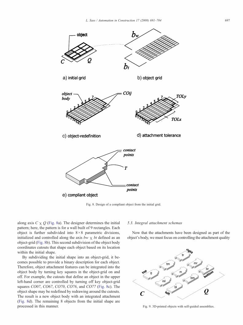
Fig. 8. Design of a compliant object from the initial grid.
Fig. 9. 3D-printed objects with self-guided assemblies.
697L. Sass / Automation in Construction 17 (2008) 691–704
along axis C χ Q (Fig. 8a). The designer determines the initialpattern; here, the pattern is for a wall built of 9 rectangles. Eachobject is further subdivided into 8×8 parametric divisions,initialized and controlled along the axis bw χ bt defined as anobject-grid (Fig. 8b). This second subdivision of the object bodycoordinates cutouts that shape each object based on its locationwithin the initial shape.
By subdividing the initial shape into an object-grid, it be-comes possible to provide a binary description for each object.Therefore, object attachment features can be integrated into theobject body by turning key squares in the object-grid on andoff. For example, the cutouts that define an object in the upperleft-hand corner are controlled by turning off key object-gridsquares CO07, CO67, CO70, CO76, and CO77 (Fig. 8c). Theobject shape may be redefined by redrawing around the cutouts.The result is a new object body with an integrated attachment(Fig. 8d). The remaining 8 objects from the initial shape areprocessed in this manner.
5.3. Integral attachment schemas
Now that the attachments have been designed as part of theobject's body, wemust focus on controlling the attachment quality
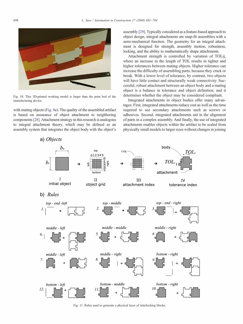
Fig. 10. This 3D-printed working model is larger than the print bed of themanufacturing device.
698 L. Sass / Automation in Construction 17 (2008) 691–704
with mating objects (Fig. 8e). The quality of the assembled artifactis based on assurance of object attachment to neighboringcomponents [28]. Attachment strategy in this research is analogousto integral attachment theory, which may be defined as anassembly system that integrates the object body with the object's
Fig. 11. Rules used to generate a phy
assembly [29]. Typically considered as a feature-based approach toobject design, integral attachments are snap-fit assemblies with asemi-mechanical function. The geometry for an integral attach-ment is designed for strength, assembly motion, robustness,locking, and the ability to mathematically shape attachments.
Attachment strength is controlled by variation of TOLij,where an increase in the length of TOL results in tighter andhigher tolerances between mating objects. Higher tolerance canincrease the difficulty of assembling parts, because they crack orbreak. With a lower level of tolerance, by contrast, two objectswill have little contact and structurally weak connectivity. Suc-cessful, robust attachment between an object body and a matingobject is a balance in tolerance and object definition, and itdetermines whether the object may be considered compliant.
Integrated attachments in object bodies offer many advan-tages. First, integrated attachments reduce cost as well as the timerequired to use secondary attachments such as screws oradhesives. Second, integrated attachments aid in the alignmentof parts in a complex assembly. And finally, the use of integratedattachments enables objects within the artifact to be scaled fromphysically small models to larger sizes without changes in joining
sical layer of interlocking blocks.

699L. Sass / Automation in Construction 17 (2008) 691–704
methods. For a detailed understanding of design constraints forintegral attachment design, see Knapp [30] for mechanicalbehavior prediction and Genc [31] and Lusher [32] for designshapes. Finally, object thickness is controlled by T, as itcontributes to the object's structure as a standing wall (Fig. 8e).
Computing a compliant object is described in Eq. (1),
Xl
C;Q
½½½T ½X
TOLi; j½X
COi; j��� ¼ k�tuples ð1Þ
Fig. 12. Physical gramm
as it returns individual objects defined by k. Compliant objectswere modeled in AutoCAD 2004 and 3D-printed on a ZCorp402 3D printer, with an envelope size of 8 in.×10 in.×8 in.The size of each object is limited by the maximum volume ofthe device envelope, which is controlled during the initializa-tion of bw χ bt (if bwNDeviceVol or btNDeviceVol=do notprint). The unique nature of each object means that thephysical assembly is self-guided; there is only one way toassemble the pieces (Fig. 9). The physical artifact in Fig. 10illustrates that objects and their assemblies are scalable and
ar rule derivation.

Fig. 14. Wall Model #1, a 3D printed artifact of a surface grid of 6×6 objectsassembled to build a free standing wall, 20”×20” (50.8 cm×50.8 cm).
700 L. Sass / Automation in Construction 17 (2008) 691–704
that it is possible to print very large artifacts from small 3Dprint devices.
6. A physical grammar
6.1. Compliant artifact
Given the compliant objects designed for assembly andmanufacturing, a grammar of rules must be defined to guide thegeneration and placement of objects within the initial shape(grid). The results of the grammar and machine processing willbe three wall models. Once the wall models are manufacturedand assembled, production success may be determined by thephysical models' ability to survive physical assembly and standfreely under their own weight without collapse.
6.2. Rule design
The first stage of the grammar generates a 2D drawing as acollection of shapes by following traditional shape grammarsyntax with shape substitution from a corresponding mark,α→β by erasing s1 with that part of s2 [12]. The first rule startswith the first square or shape in the initial grid subdivision(Fig. 8a). To clarify object construction, a simplified objectdesign is illustrated in Fig. 11a. Four steps are shown frominitialization and transformation of an object (I) to achieving a
Fig. 13. Mechanical c
compliant object with attachments and proper tolerancebetween abutting objects (IV). This shape is found after theinitial shape is subdivided into smaller shapes. Next, the ruleslisted in Fig. 11b define the application of a specific object tokey locations within the initial grid. Rule labels are edgesdefined by lines (dashes), as opposed to the traditional dot. Dashlabels are used _ (bottom), ‾ (top), and | (left or right), de-pending on the location of the dash in the initial grid. Twodashes are always found at the edges, for example|‾.
ompliance rules.
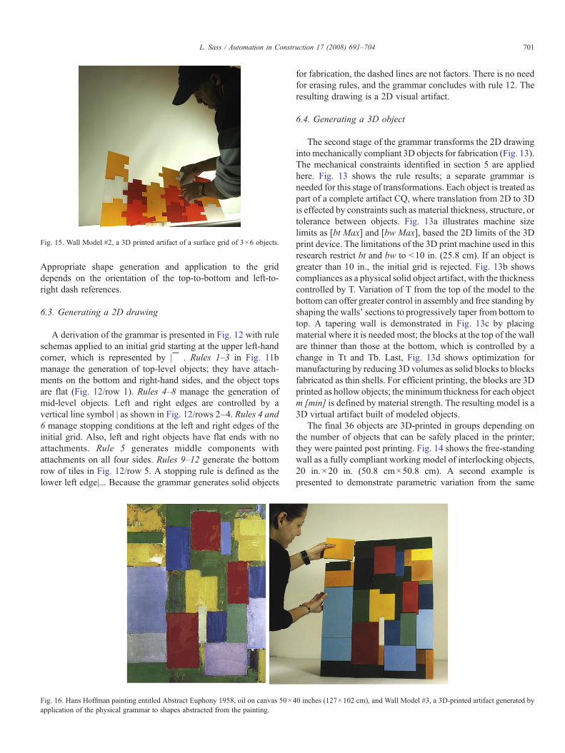
Fig. 15. Wall Model #2, a 3D printed artifact of a surface grid of 3×6 objects.
701L. Sass / Automation in Construction 17 (2008) 691–704
Appropriate shape generation and application to the griddepends on the orientation of the top-to-bottom and left-to-right dash references.
6.3. Generating a 2D drawing
A derivation of the grammar is presented in Fig. 12 with ruleschemas applied to an initial grid starting at the upper left-handcorner, which is represented by |‾ . Rules 1–3 in Fig. 11bmanage the generation of top-level objects; they have attach-ments on the bottom and right-hand sides, and the object topsare flat (Fig. 12/row 1). Rules 4–8 manage the generation ofmid-level objects. Left and right edges are controlled by avertical line symbol | as shown in Fig. 12/rows 2–4. Rules 4 and6 manage stopping conditions at the left and right edges of theinitial grid. Also, left and right objects have flat ends with noattachments. Rule 5 generates middle components withattachments on all four sides. Rules 9–12 generate the bottomrow of tiles in Fig. 12/row 5. A stopping rule is defined as thelower left edge|_. Because the grammar generates solid objects
Fig. 16. Hans Hoffman painting entitled Abstract Euphony 1958, oil on canvas 50×4application of the physical grammar to shapes abstracted from the painting.
for fabrication, the dashed lines are not factors. There is no needfor erasing rules, and the grammar concludes with rule 12. Theresulting drawing is a 2D visual artifact.
6.4. Generating a 3D object
The second stage of the grammar transforms the 2D drawinginto mechanically compliant 3D objects for fabrication (Fig. 13).The mechanical constraints identified in section 5 are appliedhere. Fig. 13 shows the rule results; a separate grammar isneeded for this stage of transformations. Each object is treated aspart of a complete artifact CQ, where translation from 2D to 3Dis effected by constraints such as material thickness, structure, ortolerance between objects. Fig. 13a illustrates machine sizelimits as [bt Max] and [bw Max], based the 2D limits of the 3Dprint device. The limitations of the 3D print machine used in thisresearch restrict bt and bw to b10 in. (25.8 cm). If an object isgreater than 10 in., the initial grid is rejected. Fig. 13b showscompliances as a physical solid object artifact, with the thicknesscontrolled by T. Variation of T from the top of the model to thebottom can offer greater control in assembly and free standing byshaping the walls' sections to progressively taper from bottom totop. A tapering wall is demonstrated in Fig. 13c by placingmaterial where it is needed most; the blocks at the top of the wallare thinner than those at the bottom, which is controlled by achange in Tt and Tb. Last, Fig. 13d shows optimization formanufacturing by reducing 3D volumes as solid blocks to blocksfabricated as thin shells. For efficient printing, the blocks are 3Dprinted as hollow objects; theminimum thickness for each objectm [min] is defined by material strength. The resulting model is a3D virtual artifact built of modeled objects.
The final 36 objects are 3D-printed in groups depending onthe number of objects that can be safely placed in the printer;they were painted post printing. Fig. 14 shows the free-standingwall as a fully compliant working model of interlocking objects,20 in.×20 in. (50.8 cm×50.8 cm). A second example ispresented to demonstrate parametric variation from the same
0 inches (127×102 cm), and Wall Model #3, a 3D-printed artifact generated by

702 L. Sass / Automation in Construction 17 (2008) 691–704
grammar of 18 objects instead of 36 objects (Fig. 15). Numbersare added at the end to the surface of each object, the number is3D geometry. It is possible to automate this application althoughthe numbers are applied manually here.
7. Integrated design
The model in Fig. 16 exemplifies an interlocking wall modelin the visual style of a Hans Hoffman painting. The wall is anintegration of a visual style and the physical grammar. The goalfor this example was to transform rectangular geometries from apainting into 3D interlocking objects. The initial grid in thisgrammar assumes that the rectangular shapes and colors found inthe original painting can be redefined as a line description forintegration into the physical grammar. This example starts whereKnight's previous grammars on paintings end with an initial gridand color definition [33]. Although grammar derivations are notpresented in this paper, abstracted lines from the painting areused to define the initial grid (Fig. 17a), followed by an object grid(Fig. 17b). Further subdivision shows rectangles redefined asobjects with attachments (Fig. 17c), and the final image shows the
Fig. 17. Starting grids a
results from applying the physical design grammar (Fig. 17d). Thefront drawing expresses the painting (visual layer), whereas thedrawing in the rear (physical layer) represents a structured attach-ment schema. Grey shapes on the visual layer of Fig. 18a illustratethe longest and widest objects in the collection. The longest shapeis scaled to 10 in. in length (bw), which is the maximum length ofthe 3D print device; bt is less than bw. Objects are then numberedon the front, and each object is 3D-printedwith the number as partof the object's geometry (Fig. 18c). The rules for structuralcompliance are then executed in Fig. 18c, resulting in a rede-finition of the artifact as a tapered wall. Finally, to lighten blocksthroughout the model, material is removed from the backside ofeach object, and the minimum thickness is determined by a ratioof part size to thickness (m[min]=1/16 in.) (Fig. 18d). Onceprinted, each objectwas painted a color that correspondedwith theHans Hoffman painting. Attachment features in the objects servedto align and partially support attachments between objects. Be-cause the 3D-printed objects were brittle, permanent connectivitybetween parts was not possible by dry friction alone. Smallamounts of silicone were applied between objects to sustainattachment. Fig. 19 shows a close-up photo of a few blocks before
nd grammar result.

Fig. 18. Application of mechanical rules applied to drawings derived from both physical and visual grammars.
703L. Sass / Automation in Construction 17 (2008) 691–704
assembly as well as a rear-view photograph of the 3D-printedblocks after assembly.
8. Results
In this research, an integrated approach to design was de-veloped by combining visual and physical production systems.A host of new problems associated with production of workingmodels from layered manufacturing machines were also
Fig. 19. Close-up of compliant objects befor
discovered. It was found that the shortcomings of the physicaldesign grammar extended from the inability to compute thenumerous variables associated with physical product manu-facturing, assembly, and review. Although grammar rulesguided the generation of geometrically compliant objects,missing in this grammar are descriptors or constraints forfeedback and testing of structural stability, object tolerance,and object assembly order prior to 3D printing. On severaloccasions, parts broke or cracked in assembly due to
e assembly and backside of final model.

704 L. Sass / Automation in Construction 17 (2008) 691–704
incompatible tolerance measures or because they wereassembled in the wrong sequence. Of course, these problemscould have been avoided with stronger print materials such asABS plastic or the resins found in stereolithography. However,as a modeling material, plaster embodies performancecharacteristics that are transferable to full-scale concreteblocks.
A second problem was that models were stable as stand-alone walls once assembled, but during assembly the modelsoften fell over or required stabilizers. This problem was due toinaccurate geometric calculations of the change in taperthickness from the bottom to the top of the wall (Tt to Tb). Inmany cases, models were assembled in a horizontal position andthen lifted to a vertical position. However, the free-standingmodels did behave as working models by informing thedesigners of future problems associated with material com-pliance and geometry, the machine limits on size and strength ofmanufactured objects, and the object/artifact form. The value insolutions for these problems increases when designs aregenerated by automated systems. For example, solutions forobject descriptions are needed if tower models similar to themodel in Fig. 1 are built of thousands of high-level objects.
In the final example, the design of the wall model combinedvisual with physical grammars, resulting in a very large workingmodel. Thus, demonstrated is the potential for an integratedvisual and physical approach. Clayton et al. raised a similarpoint outlining the need to build functional, behavioral objectsrelated to the building form [34]. Their program demonstratedthat building component generation for functional productmodels can be evaluated virtually for function and behavior.The approach presented in this paper provides additional mea-sures by addressing issues of component forming and ways tochallenge function and behavior with physical feedback.
Future goals include using a physical design grammar to testnew building forms; in particular, nonuniform curved struc-tures. We expect that physical design grammars that includedifferent types of functions associated with behavior and me-chanics will allow for the generation and testing of a vast arrayof building shapes as working models. These geometries canbe built for manufacture with layered manufacturing devicesfrom the model scale to building scale with all types of layeringmachines.
References
[1] A. Newell, Production systems: models of control structures, symposiumon cognition (8th: 1972: Carnegie-Mellon University), in: W.G. Chase(Ed.), Visual Information Processing, Academic Press, San Diego, CA,1973.
[2] G. Stiny, J. Gips, Algorithmic Aesthetics: Computer Models for Criticismand Design in the Arts, University of California Press, Berkeley, 1978.
[3] A. Gebhardt, Rapid Prototyping, Hanser, Munich, 2003.[4] C.K. Chua, K.F. Leong, C.S. Lim, Rapid Prototyping: Principles and
Application, World Scientific, River Edge, NJ, 2003.[5] I. Gibson, T. Kvan, L. Ming, Rapid prototyping for architectural models,
Rapid Prototyping J. 8 (2) (2002) 91–95.[6] J. Giannatsis, V. Dedoussis, D. Karalekas, Architectural scale modeling
using stereolithography, Rapid Prototyping J. 8 (3) (2002) 200–207.
[7] G. Ryder, B. Ion, G. Greene, D. Harrison, B. Wood, Rapid design andmanufacture tools in architecture, Autom. Constr. 11 (3) (2002) 279–290.
[8] B. Streich, Creating architecture models by computer-aided prototyping,Proc. International Conference for Computer Aided Architectural Design:Education, Research, Application, Zürich, Swiss Federal Institute of Tech-nology, 1991, pp. 279–290.
[9] L. Sass, R.O. Oxman, Materializing design, Des. Stud. 27 (3) (2006)325–355.
[10] B. Khoshnevis, Automated construction by contour crafting-relatedrobotics and information technologies, Constr. Autom. 13 (1) (2004) 1–19.
[11] R. Messler, Joining comes of age: from pragmatic process to enablingtechnology, Assem. Autom. 23 (2) (2003) 130–143.
[12] G. Stiny, Notes on the description of designs, Environ. & Plann. B 8 (3)(1981) 275-267.
[13] R. Hibbeler, Engineering Mechanics Statics and Dynamics, Prentice Hall,Upper Saddle River, NJ, 2001.
[14] M. Morgan, M. Morrison, Models as Mediators: Perspectives on Naturaland Social Science, Cambridge University Press, Cambridge, 1999.
[15] M. Morris, Models: Architecture and the Miniature, John Wiley & Son,New York, 2006.
[16] D. de Beer, L. Barnard, G. Booyen, Case study: three-dimensional plottingas a visualization aid for architectural use, Rapid Prototyping J. 10 (2)(2004) 146–151.
[17] M. Baker, Representing invention: viewing models, in: S. Chadarevian, N.Hopwood (Eds.), Models the Third Dimension of Science, StanfordUniversity Press, Stanford, CA, 2004.
[18] H. Million, Models in renaissance architecture, in: H. Million, V.Lampugunani (Eds.), The Renaissance from Brunelleshchi to Michelangelo:The Representation of Architecture, Thames and Hudson, London, 1994.
[19] J. Wilton-Ely, The Architectural Models of Sir John Soane: A Catalogue,Architectural History 12 (1969) 5–38, 81–101.
[20] M. Burry, Rapid prototyping, CAD/CAM and human factors, Autom.Constr. 11 (3) (2002) 313–333.
[21] R.F. Yates, Model Making, Including Workshop Practice, Design andConstruction of Models: A Practical Treatise for the Amateur andProfessional Mechanic, Norman W. Henley, New York, 1929.
[22] M. Morgan, M. Boumans, Secrets hidden by two-dimensionality: theeconomy as a hydraulic machine, in: S. Chadarevian, N. Hopwood (Eds.),Models the Third Dimension of Science, Stanford University Press,Stanford, CA, 2004.
[23] J. Sammet, Programming Languages: History and Fundamentals, Prentice-Hall, Englewood Cliffs, NJ, 1969.
[24] K. Cooper, Rapid Prototyping Technology: Selection and Application,Marcel Decker, New York, 2001.
[25] S. McMains, J. Smith, C. Sequin, Thin-wall calculations for layermanufacturing, J. Comput. Inf. Sci. Eng. 3 (3) (2003) 210–218.
[26] K. Brown, C. McMahon, J. Williams, Features, aka the semantics of aformal language of manufacturing, Res. Des. Eng. 7 (3) (1995) 151–172.
[27] Y. Wang, J. Duartes, Automatic generation of fabrication of designs,Autom. Constr. 11 (3) (2002) 291–302.
[28] D. Whitney, Designing assemblies, Res. Eng. Des. 11 (4) (1999) 229–253.[29] R.W. Messler Jr., Integral Mechanical Attachment: A Resurgence of the
Oldest Method of Joining, Butterworth-Heinemann, Burlington, MA,2006.
[30] K.N. Knapp, G. Gabriele, D. Lee, Stress strain response of polymers forpredicting the behavior of integral fasteners, ANTEC (1997) 1198–1202.
[31] S. Genc, R.W. Messler Jr., G.A. Gabriele, A hierarchical classificationscheme to define and order design space for integral snap-fit assembly,Res. Eng. Des. 10 (2) (1998) 94–106.
[32] A.F. Lusher, G. Gabriele, P.R. Bonenberger, R.W. Messler Jr., Aclassification scheme for integral attachment features, ANTEC 95Conference of the Society of Plastic Engineers, Boston (1995) 3783–3787.
[33] T. Knight, Tranformations of De Stijil art: the paintings of GeorgesVantongerloo and Fritz Glarner, Environ. & Plann. B 16 (4) (1989) 51–98.
[34] M. Clayton, P. Teicholz, M. Fisher, J. Kunz, Virtual components consistingof form, function, and behavior, Autom. Constr. 8 (3) (1999) 351–367.


![Pre Production Production Post Production · Pre Production [Planning] Knowledge Visual grammar (rule) Brainstorming / Theme / IDEA Reference Story / Scenario Storyboard Animatics](https://static.fdocuments.in/doc/165x107/5fda37ce684f065bfe3687ce/pre-production-production-post-production-pre-production-planning-knowledge-visual.jpg)