A PHOTOGRAMMETRIC PLOTTER DESIGNED FOR DIDACTIC ...
7
A PHOTOGRAMMETRIC PLOTTER DESIGNED FOR DIDACTIC PURPOSES M. Cunietti H. The Surveyor's topographic background must today be such as to cope with technological progress, in particular with the increasing prec! sion and the extension of cartographic documents . The knowledge of these two facts have also contributed to make photogrammetric techniques available to the Surveyor more frequently, through proper teaching and training . Often , however, schools operate on a theoretical level only , for lack of suitable instrumentation that teachers could employ for practical exer- cises . Learning is made easier and sometimes at all possible by the availability of instruments that are the practical materialization of the theoretical principles . We believe that a direct and practical involvement of the student with photogrammetric instrumentation is the indispensable requi- site for a knowledge of the photogrammetric technique sufficient to give them a valuable professional tool. In order to acquire the basic concepts of photogrammetry one must first of all understand the two fundamental phases of the photography and of the plotting. The understanding of both of these phases is made easier for younger students when they can practice on a plotting instrument. In fact, an easy to understand plotter, designed with schematic simpli- city, makes clear also the concept of the photography. Obviously, not any plotter can be particularly suitable for the purpose, but a teaching ins- trument should feature some special characteristics: it should, in other words, be intended, designed and manufactured with the aim of being an exclusively training machine, capable of making fully clear and able the principles of the photogrammetric photography and plotting . In our opinion, the main technical considerations to be made for a didac- tic plotter are the following: (a) In order to show and to make clear the conditions for photography, these should be reconstructed by making the cameras visible, by giv- ing them a configuration that reminds the taking cameras, the mecha- nism of the flight and of the exposure of the two photograms . The Politecnico di Milano Istituto tecnico "C . Cattaneo" di Milano Ottico Meccanica Italiana, Roma 163
Transcript of A PHOTOGRAMMETRIC PLOTTER DESIGNED FOR DIDACTIC ...

A PHOTOGRAMMETRIC PLOTTER DESIGNED FOR DIDACTIC PURPOSES
M. Cunietti ~~, C . Saibene~H~, H. Yzennan~HH~
The Surveyor's topographic background must today be such as to cope with technological progress, in particular with the increasing prec! sion and the extension of cartographic documents . The knowledge of these two facts have also contributed to make photogrammetric techniques available to the Surveyor more frequently, through proper teaching and training .
Often, however, schools operate on a theoretical level only, for lack of suitable instrumentation that teachers could employ for practical exercises .
Learning is made easier and sometimes at all possible by the availability of instruments that are the practical materialization of the theoretical principles . We believe that a direct and practical involvement of the student with photogrammetric instrumentation is the indispensable requisite for a knowledge of the photogrammetric technique sufficient to give them a valuable professional tool.
In order to acquire the basic concepts of photogrammetry one must first of all understand the two fundamental phases of the photography and of the plotting. The understanding of both of these phases is made easier for younger students when they can practice on a plotting instrument. In fact, an easy to understand plotter, designed with schematic simplicity, makes clear also the concept of the photography. Obviously, not any plotter can be particularly suitable for the purpose, but a teaching instrument should feature some special characteristics: i t should, in other words, be intended, designed and manufactured with the aim of being an exclusively training machine, capable of making fully clear and understan~ able the principles of the photogrammetric photography and plotting .
In our opinion, the main technical considerations to be made for a didactic plotter are the following: (a) In order to show and to make clear the conditions for photography,
these should be reconstructed by making the cameras visible, by giving them a configuration that reminds the taking cameras, the mechanism of the flight and of the exposure of the two photograms . The
~~ Politecnico di Milano ~H~ Istituto tecnico "C . Cattaneo" di Milano ~HH~ Ottico Meccanica Italiana, Roma
163

axes of the cameras should be near vertical, and the segment joini ng the two taki ng points should suggest the elementary but fundamental concept of the Base ~1d of its position in space .
(b) A condition to make photogrammeti.:i.c drills practically effective, is to make it possible for more than one student to observe the optical model at the same time. The stereoscopic observation should cover the whole model and not only a small part of it, and the instrument should not require to be operated in total darkness . An instrument having such features can only be an optical projection plotter, that is the type of plotter where the correspondence between photography and plotting is the most obvious : the plotting cameras are real optical cameras and they are similar to the taking cameras, apart from a few clearly understandable differences. Only opticalprojection plotters give the possibility to more than one person to observe th;.> whole model at the same time . The number of the possible simultaneous observers depends obviously on the magnification ratio between photographs and model that, in turn, influences the illumination level required on the whole photograph. From a technical point of view there should, in addition, be provisions for the following requirements :
(c) The elements that determine and make the interior orientation possible should be clearly visible in the plotting cameras . It is imperati ve, in fact , in order to understand the geometrical principle on which Cartographic Photogrammetry is based, to practica~ ly observe the parameters that define Interior Orientation and that make it possible to reconstruct the bundle of projecting rays .
(d) The plotting cameras should be designed to accomodate photographs havi ng the same size as at the exposure . An easy way to considerably simplify the plotting cameras would be using reduced- size photographs. The additional operation of photoreduction required in this case is didactically not desirable, since it does not have its correspondent in the real photogrammetric process, and it should not be shown to the students .
(e) The cameras must be endowed with the possibility of rotating about the three fundamental axes : also the linear base components and the vertical displacement of the cameras, along the Z axis (bz) must be possible . The latter movement could be materialized, without jeopardizing the didactic effectiveness of the instrument, with a rotation of the base in a vertical plane . It is equally instructive for the student to simulate the b-y movement of the cameras by rotating the tracing paper .
164

(f) It should be possible to make pointings inside the model; this requirement implies the existence of a floating mark. A tracing device should be associated to the mark, so that the planimetric position of model points can be transferred onto the tracing plane, as well as contour lines. The requirements discussed above are, in our opinion, the main specific technical characteristics for a 11 didactic 11 photogrammetric plotter. We wish, however, to make a few more consideration:
(g) For the correct understanding of the photogrammetric principles a high mechanical accuracy is not required. At this level of training, microscopic inaccuracies are insignificant: the instrument can be therefore designed keeping in mind that projection errors of a few tenths of a millimeter can be tolerated. It will be easy to explain the students that nothing changes conceptually when the instrumental accuracies and precision change.
(h) A limitation of the intrinsec precision does not imply that the instrument should be unstable or weak: on the contrary, a training instrument must be solid and rugged enough to withstand the stresses of its peculiar operating conditions and environment.
(i) The cost of a didactic instrument should be kept below a reasonable level, sized to the often limited budget of Educational establishments.
These ideas have been evaluated and accepted by Ottico Meccanica Italiana of Rome, Italy, manufacturers of photogrammetric equipment. The Ma~agement, the technical and commercial staff of OMI have analized the proposal of designing and manufacturing such an instrument, and put into practice the ideas discussed above .
The following technical solutions have been adopted (see figure 1).
The objectives of the plotting cameras have been specially designed: they are 4-element symmetrical lenses having an adjustable Principal Distance of 152 ± 3mm and a Relative Aperture of F30. The photographs are illuminated by a halogen-quartz 100 watt bulb and a double Fresnel condenser. The depth of field is ± 125 mm, within the projection distances of 626 mm and 875 mm (see figure 2).
The model-to-photo scale can vary between 4.2x and 5.7x approximately. The cameras move in X along the Base and rotate for lf), l.U and -~. The Z is changed by raising and lowering the camera-supporting frame: this movement is obtained with two motor-driven vertical screws. By differentially driving the ?Crews, the camera-supporting frame rotates i n a vertical plane for a true 4> rotation, as required for Absolute OrientationJ The Absolute Orientation!lis hand-controlled. The photographs are projec! ed onto a large white plastic laminated plane . At least three students on
165

on each side of the table can stereoscopically observe the entire model simultaneously by anaglyphic means (complementary-colour projection). Absolute and Relative Orientation and the model plotting are carried out with the aid of a 12x12 cm2 plate, mounted on a suitable support that rests and slides on the table plane. A luminous mark, the brightness of which can be adjusted, is located in the center of the plate: under the plate, on the same vertical axis of the mark, a liftable pencil permits marking and tracing (see figure 3).
Scales for reading the Z values, the datum of which can be adjusted, are mounted on one side of the instrument. Three large dimension and easy to read scales are supplied as standards: for 1:1000, 1:1500 and 1:3000 models (see figure 4).
The design goal, as far as prec1s1on is concerned, was for maximum allowed errors, in the model space of± 0.2 mm: systematic thorough tests are being carried out on the prototype, while the series production process is being started.
166

Figure 1
167

Figure 2
Figure 3
168
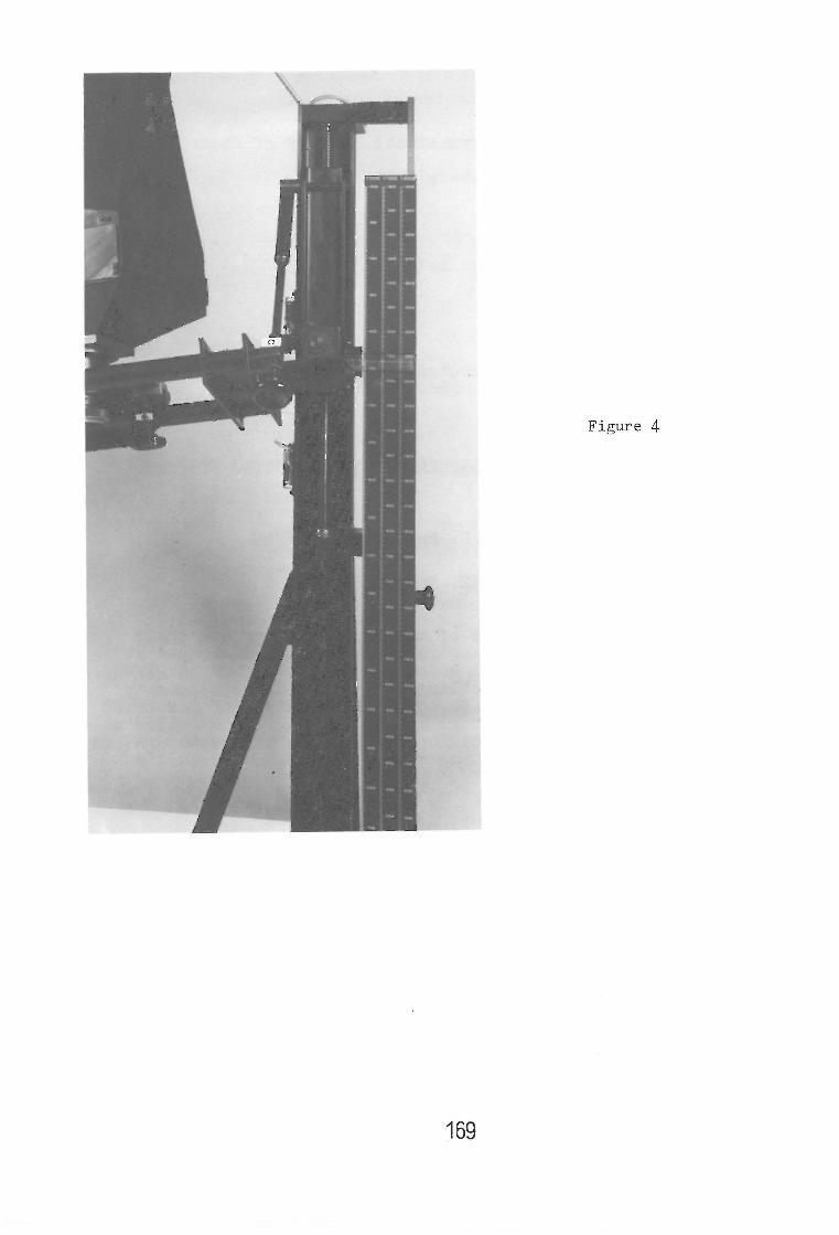
Figure 4
169