A Path-Centric Channel Assignment Framework for Cognitive Radio Wireless Networks
15
Mobile Netw Appl (2008) 13:463–476 DOI 10.1007/s11036-008-0084-y A Path-Centric Channel Assignment Framework for Cognitive Radio Wireless Networks Chunsheng Xin · Liangping Ma · Chien-Chung Shen Published online: 8 July 2008 © Springer Science + Business Media, LLC 2008 Abstract Today’s static spectrum allocation policy re- sults in a situat ion whe re the available spectrum is being exhausted while many licensed spectrum bands are under-utilized. To resolve the spectrum exhaustion problem, the cognitive radio wireless network, termed CogNet in this paper, has recently been proposed to enable unlicensed users to dynamically access the li- censed spe ctr um ban ds that are unused in eithertempo- ral or spatial domain, through spectrum-agile cognitive radios. The CogNet plays the role of secondary user in this sha red spect rum acc ess framework , and the spectrum ban ds acc ess ible by CogNets are inh er- entl y heter ogen eous and dyna mic. To esta blish the Chunsheng Xin was supported in part by National Science Foundation under grant CNS-0721313. Liangping Ma was supported in part by National Science Foundation under grant CNS-0721230. Chien-Chung Shen was supported in part by National Science Foundation under grants CNS-0721361, CNS-0347460 and CNS-0335302. C. Xin (B) Dept. of Computer Science, Norfolk State University, Norfolk, VA 23504, USA e-mail: [email protected] L. Ma Argon ST, Inc., San Diego, CA 92121, USA e-mail: [email protected] C.-C. Shen Dept. of Computer and Information Sciences, University of Delaware, Newark, DE 19716, USA e-mail: [email protected] communication infrastructure for a CogNet, the cog- nitive radio of each CogNet node detects the accessi- ble spectrum bands and chooses one as its operating freq uenc y, a proc ess termed channe l assig nment . In this paper we propose a graph-based path-centric chan- nel assignment framework to model multi-hop ad hoc CogNets and perform channel assignment from a net- wor k per spe cti ve. Simula tion res ults sho w that the path -centric chan nel assig nmen t framewor k outper- forms traditional link-centric approach. Keywords cognitive radio wireless network · dynamic spectrum access · path-centr ic channel assignment 1 Introduction Access to wireless spectrum has been chronically reg- ulated with static spectrum allocation policy since the early 20th century, where each wireless service is as- signed a fixed block of spectrum for exclusive usage. With recent rapid proliferation of wireless services, the remaining spectrum available for these new wireless services is being exhausted, which is known to be the spectrum scarcity problem in the literature [1]. Never- theless, according to studies sponsored by the Federal Communications Commission (FCC) [2, p.9–16], many allocated spectrum blocks are used only in certain ge- ographical areas and/or in short periods of time. In light of this fact, one solution to the spectrum scarcity problem is to allow other users to share the under- utilized spectrum, provided that the licensed users of such spectrum are not interfered. Since the accessibility of a block of spectrum by unlicensed users varies over
-
Upload
nazmi-aziz -
Category
Documents
-
view
215 -
download
0
Transcript of A Path-Centric Channel Assignment Framework for Cognitive Radio Wireless Networks
7/28/2019 A Path-Centric Channel Assignment Framework for Cognitive Radio Wireless Networks
http://slidepdf.com/reader/full/a-path-centric-channel-assignment-framework-for-cognitive-radio-wireless-networks 1/14
Mobile Netw Appl (2008) 13:463–476
DOI 10.1007/s11036-008-0084-y
A Path-Centric Channel Assignment Frameworkfor Cognitive Radio Wireless Networks
Chunsheng Xin · Liangping Ma · Chien-Chung Shen
Published online: 8 July 2008© Springer Science + Business Media, LLC 2008
Abstract Today’s static spectrum allocation policy re-
sults in a situation where the available spectrum isbeing exhausted while many licensed spectrum bands
are under-utilized. To resolve the spectrum exhaustion
problem, the cognitive radio wireless network, termedCogNet in this paper, has recently been proposed to
enable unlicensed users to dynamically access the li-
censed spectrum bands that are unused in either tempo-ral or spatial domain, through spectrum-agile cognitive
radios. The CogNet plays the role of secondary user
in this shared spectrum access framework, and thespectrum bands accessible by CogNets are inher-
ently heterogeneous and dynamic. To establish the
Chunsheng Xin was supported in part by National ScienceFoundation under grant CNS-0721313.
Liangping Ma was supported in part by National ScienceFoundation under grant CNS-0721230.
Chien-Chung Shen was supported in part by NationalScience Foundation under grants CNS-0721361,CNS-0347460 and CNS-0335302.
C. Xin (B)Dept. of Computer Science, Norfolk State University,Norfolk, VA 23504, USAe-mail: [email protected]
L. MaArgon ST, Inc., San Diego, CA 92121, USAe-mail: [email protected]
C.-C. ShenDept. of Computer and Information Sciences,University of Delaware, Newark, DE 19716, USAe-mail: [email protected]
communication infrastructure for a CogNet, the cog-
nitive radio of each CogNet node detects the accessi-ble spectrum bands and chooses one as its operating
frequency, a process termed channel assignment . In
this paper we propose a graph-based path-centric chan-nel assignment framework to model multi-hop ad hoc
CogNets and perform channel assignment from a net-
work perspective. Simulation results show that thepath-centric channel assignment framework outper-
forms traditional link-centric approach.
Keywords cognitive radio wireless network ·
dynamic spectrum access ·
path-centric channel assignment
1 Introduction
Access to wireless spectrum has been chronically reg-
ulated with static spectrum allocation policy since the
early 20th century, where each wireless service is as-signed a fixed block of spectrum for exclusive usage.
With recent rapid proliferation of wireless services, the
remaining spectrum available for these new wireless
services is being exhausted, which is known to be the spectrum scarcity problem in the literature [1]. Never-
theless, according to studies sponsored by the Federal
Communications Commission (FCC) [2, p.9–16], manyallocated spectrum blocks are used only in certain ge-
ographical areas and/or in short periods of time. In
light of this fact, one solution to the spectrum scarcityproblem is to allow other users to share the under-
utilized spectrum, provided that the licensed users of
such spectrum are not interfered. Since the accessibility
of a block of spectrum by unlicensed users varies over
7/28/2019 A Path-Centric Channel Assignment Framework for Cognitive Radio Wireless Networks
http://slidepdf.com/reader/full/a-path-centric-channel-assignment-framework-for-cognitive-radio-wireless-networks 2/14
464 Mobile Netw Appl (2008) 13:463–476
time, such spectrum sharing is called dynamic spectrum
access.On the policy side, FCC is currently sponsoring
studies on spectrum allocation and regulatory policies
reform to pave the way for dynamic spectrum access.
On the technology side, the spectrum-agile cognitiveradio can tune to a wide spectrum range, identify the
spectrum bands currently not being used by licensedusers, and operate on one of these available spectrumbands. The combination of advance in cognitive radio
technology and reform of spectrum allocation policy
promises to enable cognitive radio wireless networks(termed CogNets in this paper) with dynamic spec-
trum access capability. In particular, FCC released the
Notice of Proposed Rulemaking [3] in 2004 to allowunlicensed users to access idle TV channels. Since then,
there have been many studies on utilizing idle TV
channels by unlicensed users (e.g., see [4–7] and refer-
ences therein). These studies showed that although theavailability of idle TV channels varies over time, there
still exist many idle TV channels at any moment and
any location that are available to unlicensed users foreffective data communications.
In CogNets, to establish the communication in-
frastructure, each node uses its cognitive radio to detect
the accessible spectrum bands that are available for dy-namic spectrum access, and chooses one as its operating
frequency. The process of assigning a frequency band,
which is often referred to as a channel in the literature,to each radio interface as its operating frequency is
called channel assignment . Channel assignment is a ma-
jor technique to achieve high spectrum utilization and
traffic throughput. As such there have been extensiveresearch on channel assignment in multi-channel ad hoc
networks based on IEEE 802.11 [8–20]. However, so-
lutions for traditional multi-channel wireless networksare not suitable for CogNets, due to the challenges
raised by dynamic spectrum access. For example, the
algorithms in [8–12] assumed N radios at each node,one for each channel. This would result in prohibitively
high cost due to the expected high cost of cognitive
radios. The algorithms in [14–18] used two radios, and
assigned a common control channel among all nodes toone radio. Each node then uses this control channel to
dynamically negotiate a data channel for another radio
when transporting packets to a neighbor. Nevertheless,there may not exist a common channel for a CogNet
due to its role as a secondary user in dynamic spectrum
access. Furthermore, these existing algorithms implic-itly require that all channels are static and accessible at
every node, which, although offers a great convenience
for coordination in channel negotiation and switching,
is not realistic for CogNets.
More recently, the work of [21] studied channel
assignment for multi-hop ad hoc CogNets, and assumedone single radio per node. With this algorithm, CogNet
nodes form groups in a distributed operating mode,
with each group having one common channel. Groupsare connected via boundary nodes between groups by
using a time-division multiple access MAC protocol. A
boundary node switches its radio among the channelsof its connected groups at different time slots. Thedata transport between nodes in different groups goes
through the boundary nodes between groups. In other
words, such a CogNet is time-slotted and synchronizedto achieve connectivity between groups.
All the above approaches to channel assignment are
essentially link (MAC) layer solutions and considerchannel assignment/negotiation only between neigh-
boring nodes. We term these approaches as the link-
centric channel assignment. In this paper, we study
channel assignment from a network (layer) perspec-tive, and propose a path-centric channel assignment
framework for CogNets. In this path-centric frame-
work, channel assignment is driven by the routing pro-tocol and directly affects network performance such
as throughput, rather than indirectly affects network
performance from the MAC layer as by the link-centric
channel assignment. This framework is particularlydesigned for multi-hop ad hoc CogNets, although it
also works well in traditional multi-channel wireless
networks using IEEE 802.11. The framework includesboth a modeling tool named layered graph to model
CogNets and the path-centric channel assignment algo-
rithm utilizing the layered graph.
In the remainder of the paper, we first discuss inSection 2 the general assumptions for our work. Sec-
tion 3 introduces the layered graph modeling tool
for CogNet. In Section 4, we discuss the path-centricchannel assignment using the layered graph. Section 5
evaluates the performance of the path-centric chan-
nel assignment algorithm, and Section 6 concludes thepaper.
2 Assumptions and motivations
In this paper, we use a generic term channel for
a block of spectrum that was allocated to some licenseduser but is accessible for unlicensed users for dynamic
spectrum access. It can be the spectrum band of one
licensed user, e.g. a TV channel, or a sub-band di-vided from a larger spectrum band of a licensed user,
e.g., an IEEE 802.11 channel. The channels can be
either orthogonal as in IEEE 802.11 networks, or non-
orthogonal. The channels dynamically arrive/depart,
7/28/2019 A Path-Centric Channel Assignment Framework for Cognitive Radio Wireless Networks
http://slidepdf.com/reader/full/a-path-centric-channel-assignment-framework-for-cognitive-radio-wireless-networks 3/14
Mobile Netw Appl (2008) 13:463–476 465
i.e., dynamically change their status between accessi-
ble and inaccessible for unlicensed users (i.e., CogNetnodes). The channel lifetime—the duration accessible
to unlicensed users—is assumed reasonably long, e.g.,
an idle TV channel usually lasts for hours. Without
loss of generality, we assume that the cognitive radiois a single-interface radio and the interface is half du-
plex. The cognitive radio can dynamically switch amongdifferent channels, but operates on only one channelat a specific time. Our channel assignment framework
allows different nodes to have different number of cog-
nitive radios, although in practice, most nodes wouldlikely have only one radio due to the cost concern. One
major motivation of equipping more than one radio to a
CogNet node is to let the node act as a gateway to con-nect networks operating in spectrum bands significantly
apart, e.g., one network operating in channels around
900 MHz, and the other operating in channels around
2.4 GHz. Since it takes a non-negligible amount of timefor a typical radio to switch between such diversely
separated bands, it is not practical to use one radio
to connect such networks through dynamic spectrumswitching.
We assume that each CogNet node can detect both
the accessible channels and the neighbors reachable on
these channels. Furthermore, this channel informationtogether with the number of radios of each node can be
disseminated in the CogNet to every other node or to
a designated node, which then utilizes the informationto perform the path-centric channel assignment and
routing path computation for the CogNet. If there is a
control channel in the CogNet, the process of detect-
ing and disseminating accessible channels can be per-formed over the control channel. In the case that there
exists no control channel in the CogNet, we assume that
the CogNet nodes have already been self-organizedto form a preliminary communication infrastructure.
Then the channel and radio information, possibly with
other information such as traffic load statistics, canbe piggybacked as part of the routing protocol con-
trol messages, such as the link-state advertisement or
distance vector exchange. For instance, a link-centric
channel assignment algorithm such as the one describedin [21] could be utilized for CogNet self-organization
since such link-centric channel assignment algorithm
operates in a local mode, i.e., a node only talks toits neighbors to determine its channel assignment (see
Section 5 for details). However, such self-organized
CogNet usually forms sub-optimal channel assignmentand routing paths. The objective of our proposed path-
centric channel assignment framework is to configure
the network into a near-optimal communication topol-
ogy to achieve better performance.
3 Layered graph model for CogNet1
The routing path computation and channel assign-
ment in the CogNet is challenged by both the channelheterogeneity and dynamic channel arrival/departure.
Without a comprehensive modeling tool, a computed
routing path may conflict with the channel assignment
and becomes not committable. We propose a layeredgraph to model the CogNet. The graph accurately mod-
els the channel information at each node and stream-
lines the interplay between routing path computationand channel assignment for the CogNet, which results
in an easy procedure of searching shortest paths in the
graph. Since the routing path computation and channelassignment are carried out in an integrated manner,
both activities are guaranteed to be consistent with each
other. As described earlier, the discovered channels
and number of radios of every node are disseminatedto either every node or a designated node, and the
channel and radio information may be piggybacked
in the routing protocol control messages with a smalloverhead. Based on the channel and radio information,
a CogNet node constructs the layered graph as follows.
Let N denote the number of channels and G denotethe layered graph. The graph G has N logical layers,
with one layer corresponding to one channel. For each
node in the CogNet, graph G adds this node and N
subnodes associated with this node as its vertices, withone subnode in each layer. For example, for node A in
the CogNet, we add node A and subnodes A1, . . . , AN
to G , with subnode Ai in layer i of G . The edges in thecorresponding layered graph are constructed as three
different types, access, horizontal , and vertical edges, as
follows:
• Access edges connect a node to its subnodes, e.g.,
connect node A to subnode A1,• Horizontal edges connect subnodes in the same
logical layer, representing the reachability between
nodes at the channel corresponding to this logicallayer, and
• Vertical edges connect subnodes that are associated
with the same node and are in different layers,
indicating the data forwarding capability betweendifferent channels at a node.
Algorithm 1 constructs the layered graph, given a
CogNet with the channel reachability and radio infor-
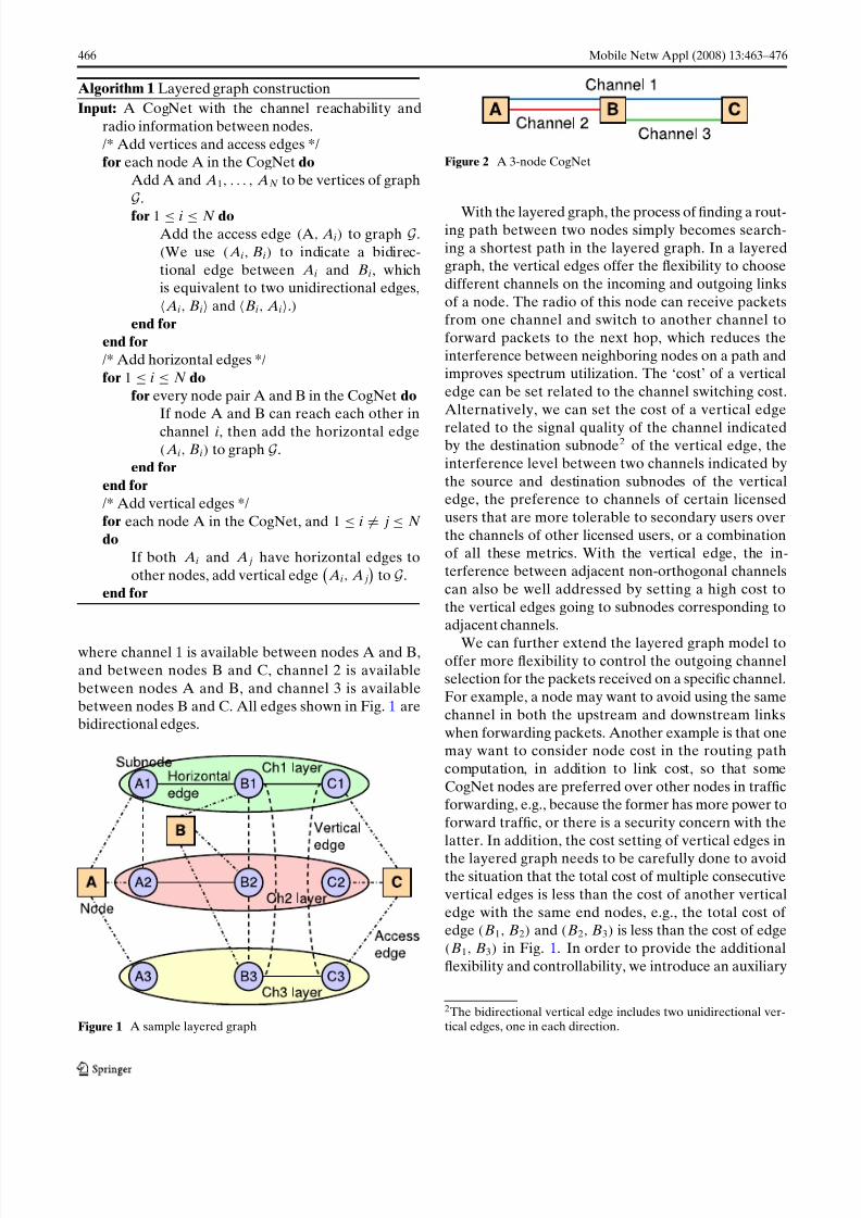
mation of each node. Figure 1 presents a constructedlayered graph for a 3-node CogNet shown in Fig. 2,
1A preliminary version of the graph model has been presented inIEEE DySPAN 2005 [22] and CrownCom 2007 [23].
7/28/2019 A Path-Centric Channel Assignment Framework for Cognitive Radio Wireless Networks
http://slidepdf.com/reader/full/a-path-centric-channel-assignment-framework-for-cognitive-radio-wireless-networks 4/14
466 Mobile Netw Appl (2008) 13:463–476
Algorithm 1 Layered graph construction
Input: A CogNet with the channel reachability and
radio information between nodes.
/* Add vertices and access edges */for each node A in the CogNet do
Add A and A1, . . . , AN to be vertices of graphG .
for 1 ≤ i ≤ N doAdd the access edge (A, Ai) to graph G .(We use ( Ai, Bi) to indicate a bidirec-
tional edge between Ai and Bi, whichis equivalent to two unidirectional edges, Ai, Bi and Bi, Ai.)
end for
end for
/* Add horizontal edges */for 1 ≤ i ≤ N do
for every node pair A and B in the CogNet do
If node A and B can reach each other in
channel i, then add the horizontal edge( Ai, Bi) to graph G .
end for
end for
/* Add vertical edges */for each node A in the CogNet, and 1 ≤ i = j ≤ N
do
If both Ai and A j have horizontal edges to
other nodes, add vertical edge Ai, A j
to G .
end for
where channel 1 is available between nodes A and B,
and between nodes B and C, channel 2 is available
between nodes A and B, and channel 3 is available
between nodes B and C. All edges shown in Fig. 1 arebidirectional edges.
Figure 1 A sample layered graph
Figure 2 A 3-node CogNet
With the layered graph, the process of finding a rout-ing path between two nodes simply becomes search-
ing a shortest path in the layered graph. In a layeredgraph, the vertical edges offer the flexibility to choose
different channels on the incoming and outgoing links
of a node. The radio of this node can receive packetsfrom one channel and switch to another channel to
forward packets to the next hop, which reduces the
interference between neighboring nodes on a path andimproves spectrum utilization. The ‘cost’ of a vertical
edge can be set related to the channel switching cost.
Alternatively, we can set the cost of a vertical edge
related to the signal quality of the channel indicatedby the destination subnode2 of the vertical edge, the
interference level between two channels indicated by
the source and destination subnodes of the verticaledge, the preference to channels of certain licensed
users that are more tolerable to secondary users over
the channels of other licensed users, or a combinationof all these metrics. With the vertical edge, the in-
terference between adjacent non-orthogonal channels
can also be well addressed by setting a high cost to
the vertical edges going to subnodes corresponding toadjacent channels.
We can further extend the layered graph model tooffer more flexibility to control the outgoing channelselection for the packets received on a specific channel.
For example, a node may want to avoid using the same
channel in both the upstream and downstream links
when forwarding packets. Another example is that onemay want to consider node cost in the routing path
computation, in addition to link cost, so that some
CogNet nodes are preferred over other nodes in trafficforwarding, e.g., because the former has more power to
forward traffic, or there is a security concern with the
latter. In addition, the cost setting of vertical edges in
the layered graph needs to be carefully done to avoidthe situation that the total cost of multiple consecutive
vertical edges is less than the cost of another vertical
edge with the same end nodes, e.g., the total cost of edge (B1, B2) and (B2, B3) is less than the cost of edge(B1, B3) in Fig. 1. In order to provide the additional
flexibility and controllability, we introduce an auxiliary
2The bidirectional vertical edge includes two unidirectional ver-tical edges, one in each direction.
7/28/2019 A Path-Centric Channel Assignment Framework for Cognitive Radio Wireless Networks
http://slidepdf.com/reader/full/a-path-centric-channel-assignment-framework-for-cognitive-radio-wireless-networks 5/14
Mobile Netw Appl (2008) 13:463–476 467
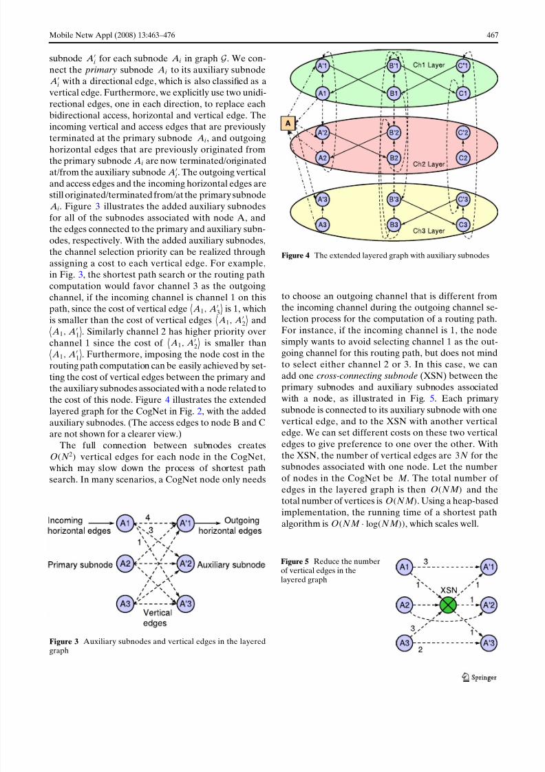
subnode Ai for each subnode Ai in graph G . We con-
nect the primary subnode Ai to its auxiliary subnode A
i with a directional edge, which is also classified as a
vertical edge. Furthermore, we explicitly use two unidi-
rectional edges, one in each direction, to replace each
bidirectional access, horizontal and vertical edge. Theincoming vertical and access edges that are previously
terminated at the primary subnode Ai, and outgoinghorizontal edges that are previously originated fromthe primary subnode Ai are now terminated/originated
at/from the auxiliary subnode Ai. The outgoing vertical
and access edges and the incoming horizontal edges arestill originated/terminated from/at the primary subnode
Ai. Figure 3 illustrates the added auxiliary subnodes
for all of the subnodes associated with node A, andthe edges connected to the primary and auxiliary subn-
odes, respectively. With the added auxiliary subnodes,
the channel selection priority can be realized through
assigning a cost to each vertical edge. For example,in Fig. 3, the shortest path search or the routing path
computation would favor channel 3 as the outgoing
channel, if the incoming channel is channel 1 on thispath, since the cost of vertical edge
A1, A
3
is 1, which
is smaller than the cost of vertical edges A1, A
2
and
A1, A1
. Similarly channel 2 has higher priority over
channel 1 since the cost of A1, A
2
is smaller than
A1, A1
. Furthermore, imposing the node cost in the
routing path computation can be easily achieved by set-
ting the cost of vertical edges between the primary andthe auxiliary subnodes associated with a node related to
the cost of this node. Figure 4 illustrates the extended
layered graph for the CogNet in Fig. 2, with the added
auxiliary subnodes. (The access edges to node B and Care not shown for a clearer view.)
The full connection between subnodes createsO(N 2) vertical edges for each node in the CogNet,which may slow down the process of shortest path
search. In many scenarios, a CogNet node only needs
Figure 3 Auxiliary subnodes and vertical edges in the layeredgraph
Figure 4 The extended layered graph with auxiliary subnodes
to choose an outgoing channel that is different fromthe incoming channel during the outgoing channel se-
lection process for the computation of a routing path.
For instance, if the incoming channel is 1, the node
simply wants to avoid selecting channel 1 as the out-going channel for this routing path, but does not mind
to select either channel 2 or 3. In this case, we can
add one cross-connecting subnode (XSN) between theprimary subnodes and auxiliary subnodes associated
with a node, as illustrated in Fig. 5. Each primary
subnode is connected to its auxiliary subnode with one
vertical edge, and to the XSN with another verticaledge. We can set different costs on these two vertical
edges to give preference to one over the other. With
the XSN, the number of vertical edges are 3N for thesubnodes associated with one node. Let the number
of nodes in the CogNet be M . The total number of
edges in the layered graph is then O(N M ) and thetotal number of vertices is O(N M ). Using a heap-based
implementation, the running time of a shortest path
algorithm is O(N M · log(N M )), which scales well.
Figure 5 Reduce the numberof vertical edges in thelayered graph

7/28/2019 A Path-Centric Channel Assignment Framework for Cognitive Radio Wireless Networks
http://slidepdf.com/reader/full/a-path-centric-channel-assignment-framework-for-cognitive-radio-wireless-networks 6/14
468 Mobile Netw Appl (2008) 13:463–476
4 Path-centric channel assignment3
The objective of switching channels in a multi-channel
wireless network is to reduce packet collision amongneighboring nodes using the same channel and thus in-
crease throughput. Such objective is the major motiva-
tion of the work in [8–20]. Nevertheless using multiple
channels is not always beneficial. In some scenarios,using a common channel for all nodes may be better.
For example, when the traffic volume traversing a node
is light, the collision should be low and thus switch-ing the radio of this node among different channels
may not be beneficial, because the channel switching
overhead may result in lower throughput than using acommon channel. On the other hand, when the traffic
volume is high, switching the radio between channels is
clearly beneficial. Therefore, whether using a common
or different channels for neighboring nodes should bedependent on the collision level, which in turn depends
on the traffic loads traversing these nodes. The traffic
load going through a specific node or link is determinedby the routing protocol. However, link-centric channel
assignment algorithms cannot capture this feature well.
This motivates us to couple routing decision with chan-nel assignment, and let channel assignment be driven
by the routing protocol, so that some nodes use a
common channel and others switch their radios among
different channels, instead of simply letting all nodesswitch radios among different channels based on a local
decision as in the previous work. Next we introduce
our path-centric channel assignment algorithm. For theease of description, we first present the algorithm in
a centralized mode, i.e., running this algorithm on a
designated node that has collected information from
every node. At the end of the section, we discuss howthis algorithm operates in a distributed mode.
We utilize both traffic information and routing path
computation to determine the channel assignment foreach node. As discussed in Section 2, the traffic load
information can be collected by every node and dissem-
inated to the network together with the channel andneighbor information, e.g., through piggybacking in the
routing protocol control messages. After the layeredgraph is constructed, we first compute the routing path
(the minimum cost path) on the layered graph betweena node pair with the largest traffic volume,4 by setting
3A preliminary version of this algorithm has been presented inCrownCom 2007 [23].4Note that instead of using traffic load information, other metricscan be used to select a node pair for processing. For example, wemay process node pairs in the order of the existing routing pathlength that is formed in the initially self-organized CogNet.
some initial cost to horizontal and vertical edges. The
cost of horizontal edges are set relevant to the trafficload on this link. The cost of vertical edges can be set to
indicate the channel switching overhead or to achieve
other objectives, as discussed earlier. Note that when
computing a routing path for a node pair, the accessedges, except the ones connected to the source and
destination node, do not participate in the computa-tion. After a routing path is computed, for each nodecorresponding to an intermediate subnode in the path,
if it has an available radio that has not been assigned
to a channel,5 we assign it to the channel correspondingto the subnode6 on the path. We call this channel as
the primary channel of this radio, because, as to be
discussed later, this radio may dynamically switch toother channels when transporting traffic between an-
other node pair. We label the subnode(s)7 of a node
that corresponds to the primary channel(s) of this
node’s radio(s) as active subnode(s) and all other sub-nodes of this node as inactive subnodes. (Initially
all nodes are unlabeled.) In other words, the subnodes
in the path determine the channel assignment of theircorresponding nodes if there are available radios in
these nodes. Next we change the edges incident to
inactive subnodes as follows: the incoming horizontal
edges and outgoing vertical edges are removed.8 Inthe routing path computation, we should not allow the
traffic to go to an inactive subnode through a hori-
zontal edge, because the corresponding node usuallydoes not have a radio tuned to the channel indicated
by this inactive subnode to receive traffic. Therefore
we remove the incoming horizontal edges incident to
an inactive subnode so that there is no routing pathgoing to an inactive subnode through a horizontal edge.
This will become more clear later in the discussion
of an example in Fig. 11. We keep the incoming ver-tical edges and outgoing horizontal edges incident to
an inactive subnode, because this would allow a node
to switch its radio from the primary channel to thechannel indicated by an inactive subnode to transport
traffic. Algorithm 2 describes the integrated routing
path computation and channel assignment. Note that
5Our algorithm is flexible to allow different nodes to have dif-ferent number of radios, and can capitalize on the scenario thatsome nodes have more than one radio.6A subnode in layer i indicates channel i. For example, subnodeA1 indicates channel 1.7In the case of the extended layered graph, the subnode hererefers to both the primary and auxiliary subnodes.8In the case of extended layered graph, both the incoming hor-izontal edges and outgoing vertical edges are incident to theprimary subnode.
7/28/2019 A Path-Centric Channel Assignment Framework for Cognitive Radio Wireless Networks
http://slidepdf.com/reader/full/a-path-centric-channel-assignment-framework-for-cognitive-radio-wireless-networks 7/14
Mobile Netw Appl (2008) 13:463–476 469
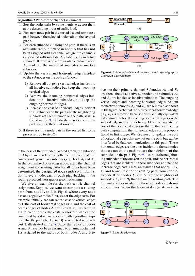
Algorithm 2 Path-centric channel assignment
1. Sort the nodes pairs by some metric, e.g., sort them
at the descending order of traffic load.
2. Pick next node pair in the sorted list and compute apath between the selected node pair on the layered
graph.
3. For each subnode Ai along the path, if there is an
available radio interface in node A that has notbeen assigned with a channel, assign it to channel i
(associated with subnode Ai), label Ai as an active
subnode. If there is no more available radio in nodeA, mark all the unlabeled subnodes as inactive
subnodes.
4. Update the vertical and horizontal edges incidentto the subnodes on the path as follows.
1) Remove all outgoing vertical edges incident toall inactive subnodes, but keep the incoming
vertical edges.
2) Remove the incoming horizontal edges inci-dent to all inactive subnodes, but keep the
outgoing horizontal edges.
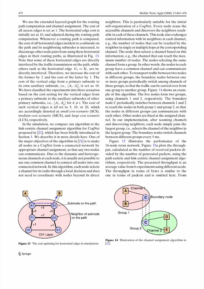
3) Increase the cost of horizontal edges incident
to all subnodes on the path and the neighboringsubnodes of each subnode on the path, as illus-
trated in Fig. 9, to indicate increased collision
probability at these links/nodes.
5. If there is still a node pair in the sorted list to beprocessed, go to step 2.
in the case of the extended layered graph, the subnodein Algorithm 2 refers to both the primary and the
corresponding auxiliary subnodes, e.g., both Ai and Ai.
In the centralized operating mode, after the channelassignment and routing paths for all nodes have been
determined, the designated node sends such informa-
tion to every node, e.g., through piggybacking in therouting protocol messages or a control channel.
We give an example for the path-centric channel
assignment. Suppose we want to compute a routing
path from node A to B in Fig. 6, where every nodehas one cognitive radio. First, we set the edge costs. For
example, initially, we can set the cost of vertical edges
as 1, the cost of horizontal edges as 2, and the cost of access edges of nodes A and B as 0, as illustrated in
Fig. 7. With these edge costs, a shortest path can be
computed by a standard shortest path algorithm. Sup-pose that the path {A, A1, B1,B} is computed, with path
cost 2, illustrated in Fig. 8. Since the radios of nodes
A and B have not been assigned to channels, channel
1 is assigned to the radios of both nodes A and B to
Figure 6 A 4-node CogNet and the constructed layered graph. aCogNet. b Layered graph
become their primary channel. Subnodes A1 and B1
are then labeled as active subnodes and subnodes A2
and B2 are labeled as inactive subnodes. The outgoingvertical edges and incoming horizontal edges incident
to inactive subnodes A2 and B2 are removed as shownin the figure. Note that the bidirectional horizontal edge( A2, B2) is removed because this is actually equivalent
to two unidirectional incoming horizontal edges, one to
subnode A2 and the other to B2. At last, we update thecost of the horizontal edges so that in the next routing
path computation, the horizontal edge cost is propor-
tional to link usage. We also need to update the costof horizontal edges that are not on the path but can be
interfered by data communication on this path. These
horizontal edges are the ones incident to the subnodes
that are not on the path but are the neighbors of thesubnodes on the path. Figure 9 illustrates the neighbor-
ing subnodes of the ones on the path, and the horizontal
edges that are incident to these subnodes and need toincrease edge cost. Here we assume that nodes F, G,
H, and K are close to the routing path from node A
to node B. Subnodes F 1 and G1 are the neighbors of subnodes A1 and B1 that are on the routing path. The
horizontal edges incident to these subnodes are drawn
as bold lines. When the horizontal edge A1 ↔ B1 is
Figure 7 Example edge costs
7/28/2019 A Path-Centric Channel Assignment Framework for Cognitive Radio Wireless Networks
http://slidepdf.com/reader/full/a-path-centric-channel-assignment-framework-for-cognitive-radio-wireless-networks 8/14
470 Mobile Netw Appl (2008) 13:463–476
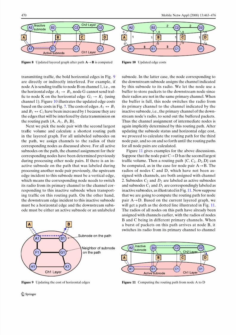
Figure 8 Updated layered graph after path A→B is computed
transmitting traffic, the bold horizontal edges in Fig. 9
are directly or indirectly interfered. For example, if
node A is sending traffic to node B on channel 1, i.e., onthe horizontal edge A1 → B1, node G cannot send traf-
fic to node K on the horizontal edge G1 → K 1 (using
channel 1). Figure 10 illustrates the updated edge costs
based on the costs in Fig. 7. The costs of edges A1 ↔ B1
and B1 ↔ C 1 have been increased by1 because they are
the edges that will be interfered by data transmission onthe routing path {A, A1, B1,B}.
Next we pick the node pair with the second largest
traffic volume and calculate a shortest routing path
in the layered graph. For all unlabeled subnodes onthe path, we assign channels to the radios of their
corresponding nodes as discussed above. For all active
subnodes on the path, the channel assignment for their
corresponding nodes have been determined previouslyduring processing other node pairs. If there is an in-
active subnode on the path that was labeled during
processing another node pair previously, the upstream
edge incident to this subnode must be a vertical edge,which means the corresponding node needs to switch
its radio from its primary channel to the channel cor-responding to this inactive subnode when transport-
ing traffic on this routing path. On the other hand,
the downstream edge incident to this inactive subnode
must be a horizontal edge and the downstream subn-ode must be either an active subnode or an unlabeled
Figure 9 Updating the cost of horizontal edges
Figure 10 Updated edge costs
subnode. In the latter case, the node corresponding to
the downstream subnode assigns the channel indicated
by this subnode to its radio. We let the node use abuffer to store packets to the downstream node since
their radios are not in the same primary channel. When
the buffer is full, this node switches the radio from
its primary channel to the channel indicated by theinactive subnode, i.e., the primary channel of the down-
stream node’s radio, to send out the buffered packets.Thus the channel assignment of intermediate nodes isagain implicitly determined by this routing path. After
updating the subnode status and horizontal edge cost,
we proceed to calculate the routing path for the thirdnode pair, and so on and so forth until the routing paths
for all node pairs are calculated.
Figure 11 gives examples for the above discussions.
Suppose that the node pair C→D has the second largesttraffic volume. Then a routing path {C, C 2, D2,D} can
be computed, as in the case for node pair A→B. The
radios of nodes C and D, which have not been as-
signed with channels, are both assigned with channel2. Subnodes C 2 and D2 are labeled as active subnodes
and subnodes C 1 and D1 are correspondingly labeled as
inactive subnodes, as illustrated in Fig. 11. Now supposethat we are going to compute the routing path for node
pair A→D. Based on the current layered graph, we
will get a path as the dotted line illustrated in Fig. 11.The radios of all nodes on this path have already been
assigned with channels earlier, with the radios of nodes
B and C being in different primary channels. Whena burst of packets on this path arrives at node B, it
switches its radio from its primary channel to channel
Figure 11 Computing the routing path from node A to D
7/28/2019 A Path-Centric Channel Assignment Framework for Cognitive Radio Wireless Networks
http://slidepdf.com/reader/full/a-path-centric-channel-assignment-framework-for-cognitive-radio-wireless-networks 9/14
Mobile Netw Appl (2008) 13:463–476 471
2 at an on-demand basis to forward packets to node
C. Note that in most link-centric channel assignmentalgorithms, nodes periodically and frequently switch
between channels to maintain link-level connectivity to
neighbors, which is not needed in our approach if there
is no traffic to the neighboring node.In the preceding discussions, we have examined how
the path-centric channel assignment algorithm operatesin the centralized mode. This algorithm can operate inthe distributed mode as well, through a similar mecha-
nism as the IP routing protocols. In this scenario, every
node collects the channel and neighbor informationtogether with traffic load statistics from all other nodes,
piggybacked in the routing protocol messages in a self-
organized CogNet, or through a control channel inthe CogNet. Each node independently runs the path-
centric channel assignment algorithm, same as above.
After running this algorithm, the routing paths between
node pairs are computed and the primary channel forthe radio of each node is determined. The difference
from the centralized mode is that in the distributed
mode, this node does not send out the channel assign-ment of each node determined by this node. Instead, it
only assigns its own radio with the channel determined
by the algorithm, and records the computed routing
paths from itself to other nodes. If every node collectsthe same or approximately the same channel and neigh-
bor information, the channel assignment for every node
that is independently determined at different nodesshould be the same or approximately the same. Thus
the channel assignment at each node in the distributed
mode is the same or approximately the same as in the
centralized mode.
5 Performance evaluation
We evaluate our algorithm in two sample networks, a16-node torus network and a 25-node random meshnetwork. Each CogNet node has one radio. In the
former topology, nodes are equally separated in a 1× 1
unit plane and the radio transmission radius of each
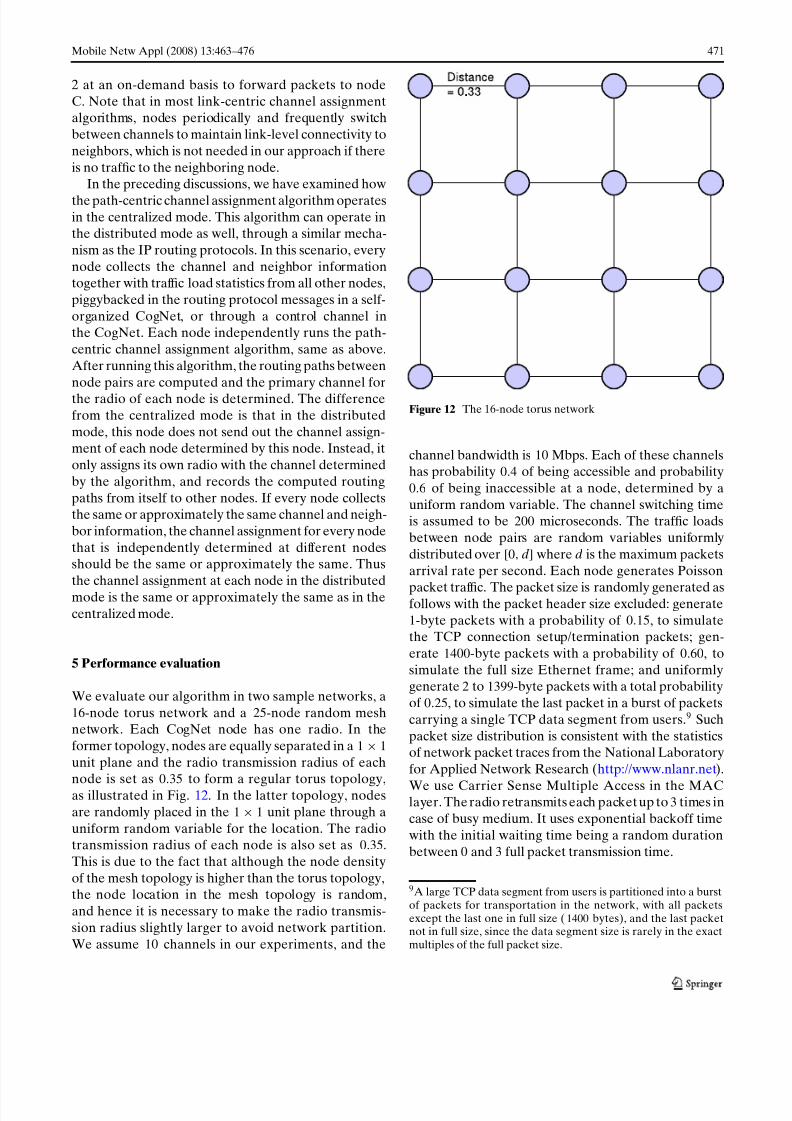
node is set as 0.35 to form a regular torus topology,as illustrated in Fig. 12. In the latter topology, nodes
are randomly placed in the 1× 1 unit plane through a
uniform random variable for the location. The radiotransmission radius of each node is also set as 0.35.
This is due to the fact that although the node density
of the mesh topology is higher than the torus topology,the node location in the mesh topology is random,
and hence it is necessary to make the radio transmis-
sion radius slightly larger to avoid network partition.
We assume 10 channels in our experiments, and the
Figure 12 The 16-node torus network
channel bandwidth is 10 Mbps. Each of these channelshas probability 0.4 of being accessible and probability0.6 of being inaccessible at a node, determined by a
uniform random variable. The channel switching timeis assumed to be 200 microseconds. The traffic loads
between node pairs are random variables uniformly
distributed over [0, d] where d is the maximum packets
arrival rate per second. Each node generates Poisson
packet traffic. The packet size is randomly generated asfollows with the packet header size excluded: generate1-byte packets with a probability of 0.15, to simulatethe TCP connection setup/termination packets; gen-
erate 1400-byte packets with a probability of 0.60, to
simulate the full size Ethernet frame; and uniformlygenerate 2 to 1399-byte packets with a total probability
of 0.25, to simulate the last packet in a burst of packets
carrying a single TCP data segment from users.9 Such
packet size distribution is consistent with the statisticsof network packet traces from the National Laboratory
for Applied Network Research (http://www.nlanr.net).
We use Carrier Sense Multiple Access in the MAClayer. The radio retransmits each packet up to3 times in
case of busy medium. It uses exponential backoff time
with the initial waiting time being a random duration
between 0 and 3 full packet transmission time.
9A large TCP data segment from users is partitioned into a burstof packets for transportation in the network, with all packetsexcept the last one in full size (1400 bytes), and the last packetnot in full size, since the data segment size is rarely in the exactmultiples of the full packet size.
7/28/2019 A Path-Centric Channel Assignment Framework for Cognitive Radio Wireless Networks
http://slidepdf.com/reader/full/a-path-centric-channel-assignment-framework-for-cognitive-radio-wireless-networks 10/14
7/28/2019 A Path-Centric Channel Assignment Framework for Cognitive Radio Wireless Networks
http://slidepdf.com/reader/full/a-path-centric-channel-assignment-framework-for-cognitive-radio-wireless-networks 11/14
Mobile Netw Appl (2008) 13:463–476 473
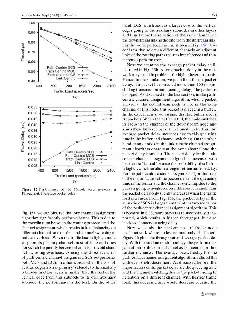
Figure 15 Performance of the 16-node torus network. aThroughput. b Average packet delay
Fig. 15a, we can observe that our channel assignmentalgorithm significantly performs better. This is due to
the coordination between the routing protocol and the
channel assignment, which results in load balancing on
different channels and on-demand channel switching toreduce overhead. When the traffic load is light, a node
stays on its primary channel most of time and does
not switch frequently between channels, to avoid chan-nel switching overhead. Among the three scenarios
of path-centric channel assignment, SCS outperforms
both MCS and LCS. In other words, when the cost of vertical edges from a (primary) subnode to the auxiliary
subnodes in other layers is smaller than the cost of the
vertical edge from this subnode to its own auxiliary
subnode, the performance is the best. On the other
hand, LCS, which assigns a larger cost to the vertical
edges going to the auxiliary subnodes in other layersand thus favors the selection of the same channel on
the downstream link as the one from the upstream link,
has the worst performance as shown in Fig. 15a. Thisconfirms that selecting different channels on adjacent
links of the routing paths reduces interference and thus
increases performance.Next we examine the average packet delay as il-
lustrated in Fig. 15b. A long packet delay in the net-
work may result in problems for higher layer protocols.
Hence, in the simulation, we put a limit for the packetdelay. If a packet has traveled more than 100 ms (in-
cluding transmission and queuing delay), the packet is
dropped. As discussed in the last section, in the path-centric channel assignment algorithm, when a packet
arrives, if the downstream node is not in the same
channel of this node, this packet is placed in a buffer.
In the experiments, we assume that the buffer size is50 packets. When the buffer is full, the node switches
its radio to the channel of the downstream node and
sends these buffered packets in a burst mode. Thus theaverage packet delay increases due to this queueing
time in the buffer and channel switching. On the other
hand, many nodes in the link-centric channel assign-
ment algorithm operate at the same channel and thepacket delay is smaller. The packet delay for the link-
centric channel assignment algorithm increases with
heavier traffic load because the probability of collisionis higher, which results in a longer retransmission delay.
For the path-centric channel assignment algorithm, one
of the major factors of the packet delay is the queueing
time in the buffer and the channel switching due to thepackets going to neighbors on a different channel. Thus
the packet delay only slightly increases when the traffic
load increases. From Fig. 15b, the packet delay in thescenario of SCS is larger than the other two scenarios
of the path-centric channel assignment algorithm. This
is because in SCS, more packets are successfully trans-ported, which results in higher throughput, but also
leads to a longer queueing delay.
Now we study the performance of the 25-node
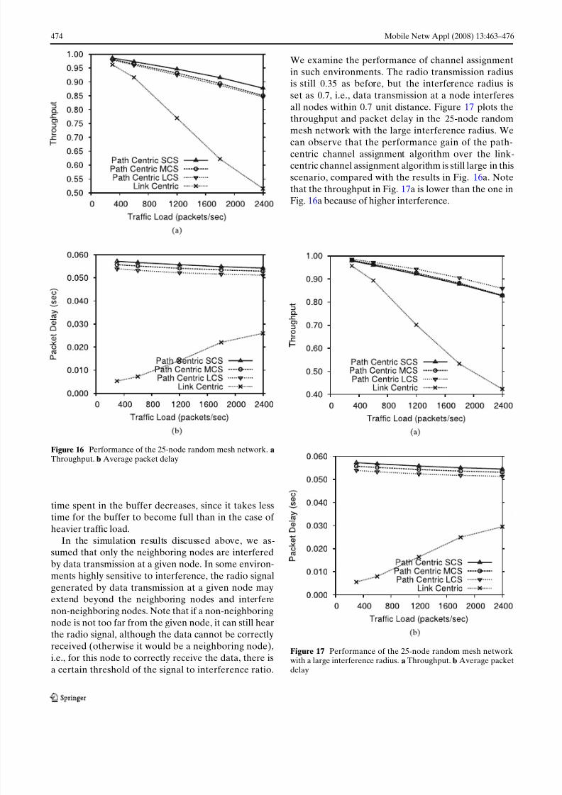
mesh network where nodes are randomly distributed.Figure 16 plots the throughput and average packet de-
lay. With the random mesh topology, the performance
gain of our path-centric channel assignment algorithmfurther increases. The average packet delay for the
path-centric channel assignment algorithm is almost flat
with even slight decrement. As discussed before, themajor factors of the packet delay are the queueing time
and the channel switching due to the packets going to
neighbors on a different channel. With heavier traffic
load, this queueing time would decrease because the
7/28/2019 A Path-Centric Channel Assignment Framework for Cognitive Radio Wireless Networks
http://slidepdf.com/reader/full/a-path-centric-channel-assignment-framework-for-cognitive-radio-wireless-networks 12/14
474 Mobile Netw Appl (2008) 13:463–476
Figure 16 Performance of the 25-node random mesh network. aThroughput. b Average packet delay
time spent in the buffer decreases, since it takes lesstime for the buffer to become full than in the case of
heavier traffic load.
In the simulation results discussed above, we as-
sumed that only the neighboring nodes are interferedby data transmission at a given node. In some environ-
ments highly sensitive to interference, the radio signal
generated by data transmission at a given node mayextend beyond the neighboring nodes and interfere
non-neighboring nodes. Note that if a non-neighboring
node is not too far from the given node, it can still hearthe radio signal, although the data cannot be correctly
received (otherwise it would be a neighboring node),
i.e., for this node to correctly receive the data, there is
a certain threshold of the signal to interference ratio.
We examine the performance of channel assignment
in such environments. The radio transmission radiusis still 0.35 as before, but the interference radius is
set as 0.7, i.e., data transmission at a node interferes
all nodes within 0.7 unit distance. Figure 17 plots thethroughput and packet delay in the 25-node random
mesh network with the large interference radius. We
can observe that the performance gain of the path-centric channel assignment algorithm over the link-centric channel assignment algorithm is still large in this
scenario, compared with the results in Fig. 16a. Note
that the throughput in Fig. 17a is lower than the one inFig. 16a because of higher interference.
Figure 17 Performance of the 25-node random mesh networkwith a large interference radius. a Throughput. b Average packetdelay

7/28/2019 A Path-Centric Channel Assignment Framework for Cognitive Radio Wireless Networks
http://slidepdf.com/reader/full/a-path-centric-channel-assignment-framework-for-cognitive-radio-wireless-networks 13/14
Mobile Netw Appl (2008) 13:463–476 475
6 Conclusion and future work
In this paper, we have proposed a path-centric channel
assignment framework for cognitive radio wireless net-works (CogNets), which takes a different perspective
from traditional channel assignment approaches for
multi-channel wireless networks. The proposed frame-
work includes both a modeling tool named layered graph for CogNets and a channel assignment algorithm
utilizing the layered graph. The framework couples
both routing and channel assignment, and determinesthe channel assignment for each node to achieve glob-
ally optimized performance, rather than focusing on the
local node with non-coordinated channel assignment.The numerical results show that the path-centric chan-
nel assignment outperforms the traditional link-centric
channel assignment algorithms. As the future work, we
plan to add the dynamics of channel arrival/departureand consider the overhead of the channel reassignment
when the working channels become inaccessible due to
the preemption by licensed users.
References
1. NTIA (2003) US frequency allocation chart. http://www.ntia.doc.gov/osmhome/allochrt.pdf
2. FCC Spectrum Policy Task Force (2002) Report of spec-trum efficiency working group. http://www.fcc.gov/sptf/files/SEWGFinalReport_1.pdf . Accessed November 2002
3. FCC (2004) Unlicensed operation in the TV broadcast bands.ET Docket No. 04-186, Notice of Proposed Rulemaking(NPRM)
4. Cordeiro C, Challapali K, Birru D, Shankar S (2005) IEEE802.22: the first wirldwide wireless standard based on cogni-tive radios. In: Proc. IEEE DySPAN, Baltimore, pp 328–337,8–11 November 2005
5. Brown T (2005) An analysis of unlicensed device operationin licensed broadcast service bands. In: Proc. IEEE DySPAN,Baltimore, pp 11–29, 8–11 November 2005
6. Leu AE, Steadman K, McHenry M, Bates J (2005) Ultra sen-sitive TV detector measurements. In: Proc. IEEE DySPAN,Baltimore, pp 30–36, 8–11 November 2005
7. Poston JD, Horne WD (2005) Discontiguous OFDM con-sideration for dynamic spectrum accessin idle TV chan-nels. In: Proc. IEEE DySPAN, Baltimore, pp 607–610, 8–11November 2005
8. Draves R, Padhye J, Zill B (2004) Routing in multi-radio,
multi-hop wireless mesh networks. In: Proc. ACM MobiCom,Philadelphia, pp 114–128, 1 October 2004
9. Nasipuri A, Das SR (1999) A multichannel CSMA MAC pro-tocol for multihop wireless networks. In: Proc. IEEE wirelesscommunications and networking conference (WCNC), NewOrleans, 21–24 September 1999
10. Nasipuri A, Das SR (2000) Multichannel CSMA with sig-nal power-based channel selection for multihop wireless net-works. In: Proc. IEEE fall vehicular technology conference(VTC), Boston, 24–28 September 2000
11. Jain N, Das SR, Nasipuri A (2001) A multichannel MACprotocol with receiver-based channel selection for multi-hop wireless networks. In: Proc. IEEE international confer-
ence on computer communication and networks (ICCCN),Phoenix, October 2001
12. Adya A, Bahl P, Padhye J, Wolman A, Zhou L (2004) Amulti-radio unification protocol for IEEE 802.11 wireless net-works. In: Proc. IEEE international conference on broad-band networks (BroadNets), San Jose, 25–29 October 2004
13. Raniwala A, Gopalan K, Chiueh T (2004) Centralized chan-nel assignment and routing algorithms for multi-channel
wireless networks. Mobile Comput Commun Rev 8(2):50–6514. Kyasanur P, Vaidya NH (2004) Routing and interface as-signment in multi-channel multi-interface wireless networks,Coordinated Science Laboratory, University of Illinois atUrbana-Champaign, Technical Report
15. Wu S-L, Lin C-Y, Tseng Y-C, Sheu J-P (2000) A new multi-channel MAC protocol with on-demand channel assignmentfor multi-hop mobile ad hoc networks. In: Proc. Int’l sympo-sium on parallel architectures, algorithms and networks (I-SPAN), Dallas, 7–9 December 2000
16. Wu S-L, Tseng Y-C, Lin C-Y, Sheu J-P (2002) A multi-channel MAC with power control for multi-hop mobile adhoc networks. Comput J 45(1):101–110
17. Hung W-C, Law E, Leon-Garcia A (2002) A dynamic multi-channel MAC for ad hoc LAN. In: Proc. 21st Biennial sym-
posium on communications, pp. 31–35, Kingston, June 200218. So J, Vaidya NH (2004) Multi-channel MAC for ad hoc net-works: handling multi-channel hidden terminals using a singletransceiver. In: Proc. ACM MobiHoc, Tokyo, pp 222–233,24–26 May 2004
19. Shacham N, King P (1987) Architectures and performancemultichannel multihop packet radio networks. IEEE J SelAreas Commun 5(6):1013–1025
20. Bahl P, Chandra R, Dunagan J (2004) SSCH: slottedseeded channel hopping for capacity improvement in IEEE802.11 ad-hoc wireless networks. In: Proc. ACM MobiCom,Philadelphia, 1 October 2004
21. Zhao J, Zheng H, Yang G-H (2005) Distributed coordinationin dynamic spectrum allocation networks. In: Proc. IEEEDySPAN, Baltimore, pp. 259–278, 8–11 November 2005
22. Xin C, Xie B, Shen C-C (2005) A novel layered graph modelfor topology formation and routing in dynamic spectrum ac-cess networks. In: Proc. IEEE DySPAN, Baltimore, pp 308–317, 8–11 November 2005
23. Xin C, Ma L, Shen C-C (2007) Path-centric channel assign-ment in cognitive radio wireless networks. In: Proc. Crown-Com, Orlando, 31 July–3 August 2007
Chunsheng Xin received the Ph.D. degree in computer sciencefrom State University of New York at Buffalo in 2002. From 2000to 2002, he was a Research Co-Op in Nokia Research Center,
7/28/2019 A Path-Centric Channel Assignment Framework for Cognitive Radio Wireless Networks
http://slidepdf.com/reader/full/a-path-centric-channel-assignment-framework-for-cognitive-radio-wireless-networks 14/14
476 Mobile Netw Appl (2008) 13:463–476
Boston. From 2002, he is an assistant professor in the ComputerScience Department, Norfolk State University, Norfolk, Virginia.His research interests include optical networks, cognitive radiowireless networks, and performance evaluation and modeling.
Liangping Ma received his B.S. degree in Physics from Wuhan
University, Hubei, China, in 1998, and his Ph.D. degree in Elec-trical Engineering from the University of Delaware, Newark,DE, in 2004. He was with the University of Delaware as aPostdoctoral Research Fellow. Since 2005, he has been with SanDiego Research Center, Inc. (now part of Argon ST, Inc.), SanDiego, CA, as a Research Staff Member. His research interestsinclude medium access control (MAC), spectrum agile radios,and signal processing.
Chien-Chung Shen received his B.S. and M.S. degrees fromNational Chiao Tung University, Taiwan, and his Ph.D. degreefrom UCLA, all in computer science. He was a senior researchscientist at Bellcore (now Telcordia) Applied Research workingon control and management of broadband networks. He is nowan associate professor in the Department of Computer and Infor-mation Sciences of the University of Delaware, and a recipientof NSF CAREER Award. His research interests include ad hoc
and sensor networks, dynamic spectrum management, controland management of broadband networks, distributed object andpeer-to-peer computing, and simulation. He is a member of bothACM and IEEE.