A Parylene Bellows Electrochemical...
14
JOURNAL OF MICROELECTROMECHANICAL SYSTEMS, VOL. 19, NO. 1, FEBRUARY 2010 215 A Parylene Bellows Electrochemical Actuator Po-Ying Li, Member, IEEE, Member, ASME, Roya Sheybani, Christian A. Gutierrez, Jonathan T. W. Kuo, and Ellis Meng, Senior Member, IEEE, Member, ASME Abstract—We present the first electrochemical actuator with Parylene bellows for large-deflection operation. The bellows di- aphragm was fabricated using a polyethylene-glycol-based sacrifi- cial molding technique followed by coating in Parylene C. Bellows were mechanically characterized and integrated with a pair of interdigitated electrodes to form an electrochemical actuator that is suitable for low-power pumping of fluids. Pump performance (gas generation rate and pump efficiency) was optimized through a careful examination of geometrical factors. Overall, a maximum pump efficiency of 90% was achieved in the case of electroplated electrodes, and a deflection of over 1.5 mm was demonstrated. Real-time wireless operation was achieved. The complete fabri- cation process and the materials used in this actuator are bio- compatible, which makes it suitable for biological and medical applications. [2009-0095] Index Terms—Bellows, drug delivery device, electrolysis pump, intraocular implant. I. I NTRODUCTION A FTER SEVERAL decades of development, many micro- pumps, including mechanical and nonmechanical, have been demonstrated [1]. Mechanical micropumps may incorpo- rate check valve [2] or valveless [3] approaches to regulate flow direction and include a compliant element for pumping. Typically, large flow rates can be realized (> 10 μL/min). Nonmechanical pumps are driven by electrohydrodynamic [4], electrowetting [5], magnetohydrodynamic [6], phase transfor- mation [7], or electrochemical [8] principles but usually suffer from low achievable flow rates (< 10 μL/min). Among them, electrochemically driven mechanical pumps feature low power consumption, low heat generation, accurate flow control, and large driving force [9], [10]. These factors, combined with the potential for biocompatible construction, afford many interest- ing biological and medical applications. Implantable microelectromechanical systems (MEMS) pumps are still an active area of research; specifically, Manuscript received April 16, 2009; revised August 18, 2009. First published December 4, 2009; current version published February 3, 2010. This work was supported in part by the National Institutes of Health (NIH)/National Eye Institute (NEI) under Award R21EY018490 and in part by a Wallace H. Coulter Foundation Early Career Translational Research Award. Subject Editor C. H. Mastrangelo. P.-Y. Li is with the Department of Electrical Engineering, University of Southern California, Los Angeles, CA 90089 USA (e-mail: [email protected]). R. Sheybani, C. A. Gutierrez, and J. T. W. Kuo are with the Department of Biomedical Engineering, University of Southern California, Los Angeles, CA 90089 USA (e-mail: [email protected]; [email protected]; jonathtk@ usc.edu). E. Meng is with the Department of Biomedical Engineering and the Depart- ment of Electrical Engineering, University of Southern California, Los Angeles, CA 90089 USA (e-mail: [email protected]). Color versions of one or more of the figures in this paper are available online at http://ieeexplore.ieee.org. Digital Object Identifier 10.1109/JMEMS.2009.2032670 achieving integration of the entire pumping systems remains difficult. Although many nonmechanical pumps cite the possibility of use in drug delivery applications, clinical or in vivo experimental data are rarely seen. Most implantable pumps in literature are still mechanical [11]. The major design concerns for an implantable drug delivery system are as follows: applied voltage, power consumption, dosing accuracy, concentration, frequency, duration, toxicity, drug interaction, and allergies. Previously, we reported a drug delivery system integrated with an electrochemical micropump for the treatment of in- traocular diseases [12]. This pump was integrated with an interdigitated electrode to induce electrochemical phase change of liquid water into hydrogen and oxygen gas for drug delivery. However, oxidation of the drug was observed due to the direct electrolysis of the drug during pumping. Therefore, a separate pumping chamber is required to prevent drug degradation and unwanted pH changes. A simple solution is to mechanically couple the pumping chamber to the drug through a flexible diaphragm. Parylene diaphragms are widely used in micropumps be- cause of their advantageous properties compared to other thin film materials [13], [14]. First, it is a United States Pharma- copeia class VI polymer and highly inert. It is also compatible with MEMS microfabrication. In addition, Parylene has low Young’s modulus which grants large displacement in fabri- cated diaphragms with low applied pressure. Several Parylene diaphragm geometries have been investigated: flat [15]–[17], dome [18], corrugated [13], [15], [19], [20], and bellows [21], [22]. Among them, corrugated diaphragms and bellows pro- vide the largest deflections (> 1 mm), possess low intrinsic stress, and thus are less likely to undergo plastic deformation compared to flat and dome diaphragms. Corrugated diaphragm fabrication, however, is complex due to the requirement of deep corrugation trenches for large-deflection membrane. Current etching technologies such as wet chemical etching and dry plasma etching are both limited to the substrate thickness (∼500 μm for 3–4-in Si wafers). Therefore, the practically achievable corrugation depth is less than 500 μm and places a limit on deflection. Meanwhile, wet-etched corrugations may be associated with residual stress which may result in deforma- tion during the substrate release step. Microbellows are also difficult to fabricate due to the hori- zontal convolutions comprising the bellows structure. A com- mon process to produce each bellows convolution involves the deposition and patterning of the sacrificial layer followed by the diaphragm material. By repeating these steps, sili- con nitride microbellows were fabricated [23]. An alternative process resulted in Parylene bellows by using a wax mold as 1057-7157/$26.00 © 2009 IEEE Authorized licensed use limited to: University of Southern California. Downloaded on February 16,2010 at 11:44:45 EST from IEEE Xplore. Restrictions apply.
Transcript of A Parylene Bellows Electrochemical...
JOURNAL OF MICROELECTROMECHANICAL SYSTEMS, VOL. 19, NO. 1, FEBRUARY 2010 215
A Parylene Bellows Electrochemical ActuatorPo-Ying Li, Member, IEEE, Member, ASME, Roya Sheybani, Christian A. Gutierrez,
Jonathan T. W. Kuo, and Ellis Meng, Senior Member, IEEE, Member, ASME
Abstract—We present the first electrochemical actuator withParylene bellows for large-deflection operation. The bellows di-aphragm was fabricated using a polyethylene-glycol-based sacrifi-cial molding technique followed by coating in Parylene C. Bellowswere mechanically characterized and integrated with a pair ofinterdigitated electrodes to form an electrochemical actuator thatis suitable for low-power pumping of fluids. Pump performance(gas generation rate and pump efficiency) was optimized througha careful examination of geometrical factors. Overall, a maximumpump efficiency of 90% was achieved in the case of electroplatedelectrodes, and a deflection of over 1.5 mm was demonstrated.Real-time wireless operation was achieved. The complete fabri-cation process and the materials used in this actuator are bio-compatible, which makes it suitable for biological and medicalapplications. [2009-0095]
Index Terms—Bellows, drug delivery device, electrolysis pump,intraocular implant.
I. INTRODUCTION
A FTER SEVERAL decades of development, many micro-pumps, including mechanical and nonmechanical, have
been demonstrated [1]. Mechanical micropumps may incorpo-rate check valve [2] or valveless [3] approaches to regulateflow direction and include a compliant element for pumping.Typically, large flow rates can be realized (> 10 μL/min).Nonmechanical pumps are driven by electrohydrodynamic [4],electrowetting [5], magnetohydrodynamic [6], phase transfor-mation [7], or electrochemical [8] principles but usually sufferfrom low achievable flow rates (< 10 μL/min). Among them,electrochemically driven mechanical pumps feature low powerconsumption, low heat generation, accurate flow control, andlarge driving force [9], [10]. These factors, combined with thepotential for biocompatible construction, afford many interest-ing biological and medical applications.
Implantable microelectromechanical systems (MEMS)pumps are still an active area of research; specifically,
Manuscript received April 16, 2009; revised August 18, 2009. First publishedDecember 4, 2009; current version published February 3, 2010. This workwas supported in part by the National Institutes of Health (NIH)/NationalEye Institute (NEI) under Award R21EY018490 and in part by a Wallace H.Coulter Foundation Early Career Translational Research Award. Subject EditorC. H. Mastrangelo.
P.-Y. Li is with the Department of Electrical Engineering, University ofSouthern California, Los Angeles, CA 90089 USA (e-mail: [email protected]).
R. Sheybani, C. A. Gutierrez, and J. T. W. Kuo are with the Departmentof Biomedical Engineering, University of Southern California, Los Angeles,CA 90089 USA (e-mail: [email protected]; [email protected]; [email protected]).
E. Meng is with the Department of Biomedical Engineering and the Depart-ment of Electrical Engineering, University of Southern California, Los Angeles,CA 90089 USA (e-mail: [email protected]).
Color versions of one or more of the figures in this paper are available onlineat http://ieeexplore.ieee.org.
Digital Object Identifier 10.1109/JMEMS.2009.2032670
achieving integration of the entire pumping systems remainsdifficult. Although many nonmechanical pumps cite thepossibility of use in drug delivery applications, clinical orin vivo experimental data are rarely seen. Most implantablepumps in literature are still mechanical [11]. The major designconcerns for an implantable drug delivery system are asfollows: applied voltage, power consumption, dosing accuracy,concentration, frequency, duration, toxicity, drug interaction,and allergies.
Previously, we reported a drug delivery system integratedwith an electrochemical micropump for the treatment of in-traocular diseases [12]. This pump was integrated with aninterdigitated electrode to induce electrochemical phase changeof liquid water into hydrogen and oxygen gas for drug delivery.However, oxidation of the drug was observed due to the directelectrolysis of the drug during pumping. Therefore, a separatepumping chamber is required to prevent drug degradation andunwanted pH changes. A simple solution is to mechanicallycouple the pumping chamber to the drug through a flexiblediaphragm.
Parylene diaphragms are widely used in micropumps be-cause of their advantageous properties compared to other thinfilm materials [13], [14]. First, it is a United States Pharma-copeia class VI polymer and highly inert. It is also compatiblewith MEMS microfabrication. In addition, Parylene has lowYoung’s modulus which grants large displacement in fabri-cated diaphragms with low applied pressure. Several Parylenediaphragm geometries have been investigated: flat [15]–[17],dome [18], corrugated [13], [15], [19], [20], and bellows [21],[22]. Among them, corrugated diaphragms and bellows pro-vide the largest deflections (> 1 mm), possess low intrinsicstress, and thus are less likely to undergo plastic deformationcompared to flat and dome diaphragms. Corrugated diaphragmfabrication, however, is complex due to the requirement of deepcorrugation trenches for large-deflection membrane. Currentetching technologies such as wet chemical etching and dryplasma etching are both limited to the substrate thickness(∼500 μm for 3–4-in Si wafers). Therefore, the practicallyachievable corrugation depth is less than 500 μm and placesa limit on deflection. Meanwhile, wet-etched corrugations maybe associated with residual stress which may result in deforma-tion during the substrate release step.
Microbellows are also difficult to fabricate due to the hori-zontal convolutions comprising the bellows structure. A com-mon process to produce each bellows convolution involvesthe deposition and patterning of the sacrificial layer followedby the diaphragm material. By repeating these steps, sili-con nitride microbellows were fabricated [23]. An alternativeprocess resulted in Parylene bellows by using a wax mold as
1057-7157/$26.00 © 2009 IEEE
Authorized licensed use limited to: University of Southern California. Downloaded on February 16,2010 at 11:44:45 EST from IEEE Xplore. Restrictions apply.
216 JOURNAL OF MICROELECTROMECHANICAL SYSTEMS, VOL. 19, NO. 1, FEBRUARY 2010
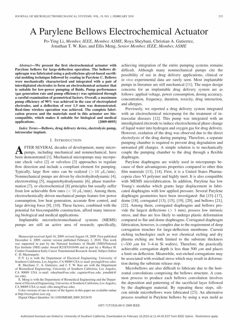
Fig. 1. Parylene bellows electrochemical actuator for ocular drug delivery: (a) Exploded view of the actuator showing the major components, (b) example of theactuator assembled into a drug delivery system, and (c) conceptual depiction of the implanted intraocular drug delivery device. The device is implanted under theconjunctiva (within the eyewall) with the cannula directed through an incision into the anterior segment of eye.
a sacrificial material [21], [22]. Other technologies involved inmicrobellows fabrication are microstereolithography [24] andfocused-ion-beam chemical vapor deposition [25]. For micro-machining and wax molding, acid or solvent is required forremoval of the sacrificial materials. Elevated temperatures en-countered during sacrificial release may also induce residualstress in the bellows.
Polyethylene glycol (PEG), a biocompatible and water-soluble polymer [26], is a widely used biomedical material.It is patternable by conventional photolithography [27] andsoft lithography [28]. Casting of PEG structures for corrugatedParylene diaphragm was reported [29]. A maximum deflectionof 0.9 mm was demonstrated for a 2.6-mm-diameter corrugateddiaphragm. Microbellows, however, have not yet been realizedby coating over sacrificial PEG casts.
Here, we present a novel Parylene bellows electrochemicalactuator. The Parylene bellows is fabricated using a sacrificialPEG molding technique followed by Parylene coating. Onlybiocompatible materials and solutions are used to produce theParylene bellows. The large convolutions offer large deflectionunder a low actuation pressure. By combining the bellowswith a pair of interdigitated electrodes, a complete actuatorsystem was assembled. In the literature, characterization ofohmic loss [30] of, electrosynthesis [31] with, and electrochem-ical sensing [32] using interdigitated microelectrodes wereinvestigated. However, the relationship between interdigitatedelectrode geometry (specifically electrode element width andspacing) and pump efficiency is not fully characterized. There-fore, an experimental method to evaluate the pump performancebased on efficiency was pursued. Actuator performance was
characterized, including flow rate, efficiency, real-time pressuregeneration, and wireless operation.
II. DESIGN
Key actuator features include the following: 1) separationof the electrochemical reaction from the pumped solution bya robust high-deflection Parylene bellows; 2) an efficiency-optimized electrolysis electrode design to minimize power con-sumption for long-term wireless operation; and 3) constructionfrom biocompatible materials.
The pump actuator consists of interdigitated platinum elec-trodes and Parylene bellows that are fabricated separately.Assembly involves first filling the bellows with deionized (DI)water and then joining it to the electrode base to seal the elec-trochemical chamber [Fig. 1(a)]. The interdigitated electrodegeometry minimizes the resistive path through the solution toimprove pumping efficiency and reduce heat generation [30].Electrolysis pumping is selected over other actuation methodsfor its low power consumption (from approximately microwattsto milliwatts) which is achieved without compromising deflec-tion and force (Fig. 2).
Bellows provide large displacement while requiring minimaldriving force compared to other commonly used diaphragmgeometries. For example, a flat membrane has very limiteddeflection and thus is only suitable for low-flow applications[23]. Large deflections are possible but at the cost of large mem-brane size. Corrugated membranes achieve larger deflectionwithout significant increase in size. However, deep corrugations(> 1 mm) are difficult to fabricate, and only a limited number
Authorized licensed use limited to: University of Southern California. Downloaded on February 16,2010 at 11:44:45 EST from IEEE Xplore. Restrictions apply.
LI et al.: PARYLENE BELLOWS ELECTROCHEMICAL ACTUATOR 217
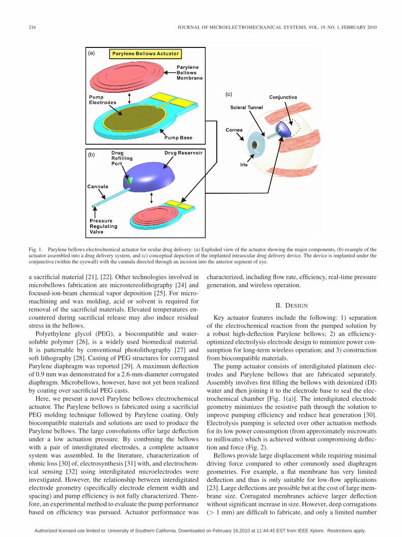
Fig. 2. Illustration of wireless operation of the intraocular drug deliverysystem: (a) power off and (b) power on.
or corrugations fit within a given diaphragm area. These factorsimpose a practical limit to deflection achievable with corrugateddiaphragms. Bellows grant the largest displacement of thesethree options (flat, corrugated, and bellows diaphragms) with aminimal increase in overall thickness. Fabrication of bellows bystandard lithographic processes is repetitive and time consum-ing [23]. A simple lithography-less approach to bellows fabri-cation was devised here to produce flexible Parylene bellows.
Our specific application of interest is a micropump for oculardrug delivery [Fig. 1(b) and (c)]; the envisioned system consistsof a reservoir containing the actuator and a cannula throughwhich drug is dosed. The reservoir body is implanted withinthe eye wall, while the cannula is inserted through an incisionand directed to the site of therapy in the intraocular space.Wirelessly-transferred power is applied to the interdigitatedelectrodes to induce electrolysis (phase change of water intohydrogen and oxygen gas), which results in an internal pressureincrease within the actuator and inflates the bellows [Fig. 2(b)].The inflated bellows drives the drug through the cannula intothe eye, while the gases remain trapped inside the pumpchamber, preventing undesirable contact with the drug. Controlof drug delivery can be achieved by adding a dual-regulatingcheck valve connected to the end of the cannula to prevent bothbackflow of the drug into the device and accidental deliveryresulting from transient pressure fluctuations (e.g., as a resultof flying or sneezing) [33].
III. THEORY AND MODELING
A. Electrolysis Actuation Using Microelectrodes
Electrolysis of water was selected as the actuation mech-anism for low power consumption, high pump efficiency,
simple structure, and ability to generate large displacements[9], [34].
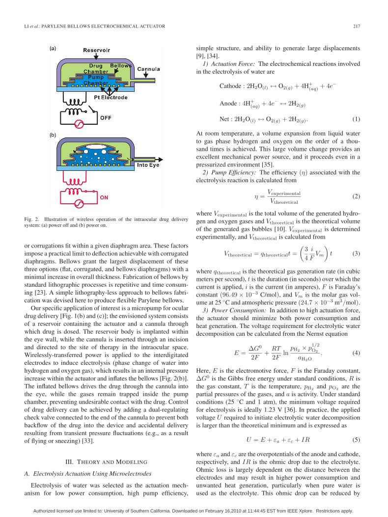
1) Actuation Force: The electrochemical reactions involvedin the electrolysis of water are
Cathode : 2H2O(l) ↔ O2(g) + 4H+(aq) + 4e−
Anode : 4H+(aq) + 4e− ↔ 2H2(g)
Net : 2H2O(l) ↔ O2(g) + 2H2(g). (1)
At room temperature, a volume expansion from liquid waterto gas phase hydrogen and oxygen on the order of a thou-sand times is achieved. This large volume change provides anexcellent mechanical power source, and it proceeds even in apressurized environment [35].
2) Pump Efficiency: The efficiency (η) associated with theelectrolysis reaction is calculated from
η =Vexperimental
Vtheoretical(2)
where Vexperimental is the total volume of the generated hydro-gen and oxygen gases and Vtheoretical is the theoretical volumeof the generated gas bubbles [10]. Vexperimental is determinedexperimentally, and Vtheoretical is calculated from
Vtheoretical = qtheoreticalt =(
34
i
FVm
)t (3)
where qtheoretical is the theoretical gas generation rate (in cubicmeters per second), t is the duration (in seconds) over which thecurrent is applied, i is the current (in amperes), F is Faraday’sconstant (96.49 × 10⁻³ C/mol), and Vm is the molar gas vol-ume at 25 ◦C and atmospheric pressure (24.7 × 10⁻³ m3/mol).
3) Power Consumption: In addition to high actuation force,the actuator should minimize both power consumption andheat generation. The voltage requirement for electrolytic waterdecomposition can be calculated from the Nernst equation
E =ΔG0
2F+
RT
2Fln
pH2 × p1/2O2
aH2O. (4)
Here, E is the electromotive force, F is the Faraday constant,ΔG0 is the Gibbs free energy under standard conditions, R isthe gas constant, T is the temperature, pH2 and pO2 are thepartial pressures of the gases, and a is activity. Under standardconditions (25 ◦C and 1 atm), the minimum voltage requiredfor electrolysis is ideally 1.23 V [36]. In practice, the appliedvoltage U required to initiate electrolytic water decompositionis larger than the theoretical minimum and is expressed as
U = E + εa + εc + IR (5)
where εa and εc are the overpotentials of the anode and cathode,respectively, and IR is the ohmic drop due to the electrolyte.Ohmic loss is largely dependent on the distance between theelectrodes and may result in higher power consumption andunwanted heat generation, particularly when pure water isused as the electrolyte. This ohmic drop can be reduced by
Authorized licensed use limited to: University of Southern California. Downloaded on February 16,2010 at 11:44:45 EST from IEEE Xplore. Restrictions apply.
218 JOURNAL OF MICROELECTROMECHANICAL SYSTEMS, VOL. 19, NO. 1, FEBRUARY 2010
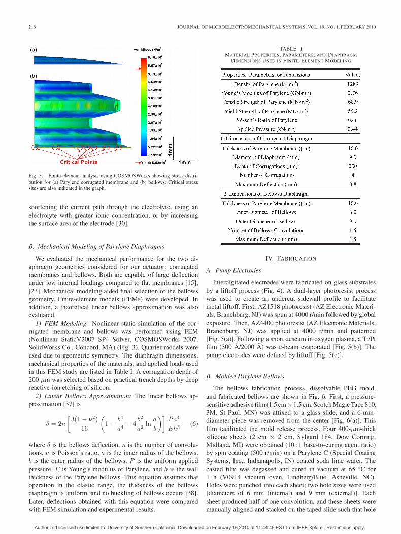
Fig. 3. Finite-element analysis using COSMOSWorks showing stress distri-bution for (a) Parylene corrugated membrane and (b) bellows. Critical stresssites are also indicated in the graph.
shortening the current path through the electrolyte, using anelectrolyte with greater ionic concentration, or by increasingthe surface area of the electrode [30].
B. Mechanical Modeling of Parylene Diaphragms
We evaluated the mechanical performance for the two di-aphragm geometries considered for our actuator: corrugatedmembranes and bellows. Both are capable of large deflectionunder low internal loadings compared to flat membranes [15],[23]. Mechanical modeling aided final selection of the bellowsgeometry. Finite-element models (FEMs) were developed. Inaddition, a theoretical linear bellows approximation was alsoevaluated.
1) FEM Modeling: Nonlinear static simulation of the cor-rugated membrane and bellows was performed using FEM(Nonlinear StaticV2007 SP4 Solver, COSMOSWorks 2007,SolidWorks Co., Concord, MA) (Fig. 3). Quarter models wereused due to geometric symmetry. The diaphragm dimensions,mechanical properties of the materials, and applied loads usedin this FEM study are listed in Table I. A corrugation depth of200 μm was selected based on practical trench depths by deepreactive-ion etching of silicon.
2) Linear Bellows Approximation: The linear bellows ap-proximation [37] is
δ = 2n
[3(1 − ν2)
16
(1 − b4
a4− 4
b2
a2ln
a
b
)]Pa4
Eh3(6)
where δ is the bellows deflection, n is the number of convolu-tions, ν is Poisson’s ratio, a is the inner radius of the bellows,b is the outer radius of the bellows, P is the uniform appliedpressure, E is Young’s modulus of Parylene, and h is the wallthickness of the Parylene bellows. This equation assumes thatoperation in the elastic range, the thickness of the bellowsdiaphragm is uniform, and no buckling of bellows occurs [38].Later, deflections obtained with this equation were comparedwith FEM simulation and experimental results.
TABLE IMATERIAL PROPERTIES, PARAMETERS, AND DIAPHRAGM
DIMENSIONS USED IN FINITE-ELEMENT MODELING
IV. FABRICATION
A. Pump Electrodes
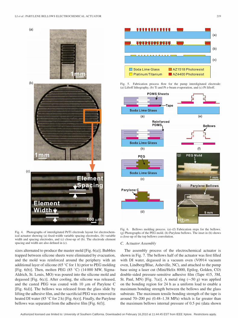
Interdigitated electrodes were fabricated on glass substratesby a liftoff process (Fig. 4). A dual-layer photoresist processwas used to create an undercut sidewall profile to facilitatemetal liftoff. First, AZ1518 photoresist (AZ Electronic Materi-als, Branchburg, NJ) was spun at 4000 r/min followed by globalexposure. Then, AZ4400 photoresist (AZ Electronic Materials,Branchburg, NJ) was applied at 4000 r/min and patterned[Fig. 5(a)]. Following a short descum in oxygen plasma, a Ti/Ptfilm (300 Å/2000 Å) was e-beam evaporated [Fig. 5(b)]. Thepump electrodes were defined by liftoff [Fig. 5(c)].
B. Molded Parylene Bellows
The bellows fabrication process, dissolvable PEG mold,and fabricated bellows are shown in Fig. 6. First, a pressure-sensitive adhesive film (1.5 cm×1.5 cm, Scotch Magic Tape 810,3M, St Paul, MN) was affixed to a glass slide, and a 6-mm-diameter piece was removed from the center [Fig. 6(a)]. Thisfilm facilitated the mold release process. Four 400-μm-thicksilicone sheets (2 cm × 2 cm, Sylgard 184, Dow Corning,Midland, MI) were obtained (10 : 1 base-to-curing agent ratio)by spin coating (500 r/min) on a Parylene C (Special CoatingSystems, Inc., Indianapolis, IN) coated soda lime wafer. Thecasted film was degassed and cured in vacuum at 65 ◦C for1 h (V0914 vacuum oven, Lindberg/Blue, Asheville, NC).Holes were punched into each sheet; two hole sizes were used[diameters of 6 mm (internal) and 9 mm (external)]. Eachsheet produced half of one convolution, and these sheets weremanually aligned and stacked on the taped slide such that hole
Authorized licensed use limited to: University of Southern California. Downloaded on February 16,2010 at 11:44:45 EST from IEEE Xplore. Restrictions apply.
LI et al.: PARYLENE BELLOWS ELECTROCHEMICAL ACTUATOR 219
Fig. 4. Photographs of interdigitated Pt/Ti electrode layout for electrochem-ical actuator showing (a) fixed-width variable spacing electrodes, (b) variablewidth and spacing electrodes, and (c) close-up of (b). The electrode elementspacing and width are also defined in (c).
sizes alternated to produce the master mold [Fig. 6(a)]. Bubblestrapped between silicone sheets were eliminated by evacuation,and the mold was reinforced around the periphery with anadditional layer of silicone (65 ◦C for 1 h) prior to PEG molding[Fig. 6(b)]. Then, molten PEG (85 ◦C) (14 000 MW, Sigma-Aldrich, St. Louis, MO) was poured into the silicone mold anddegassed [Fig. 6(c)]. After cooling, the silicone was released,and the casted PEG was coated with 10 μm of Parylene C[Fig. 6(d)]. The bellows was released from the glass slide bylifting the adhesive film, and the sacrificial PEG was removed inheated DI water (85 ◦C for 2 h) [Fig. 6(e)]. Finally, the Parylenebellows was separated from the adhesive film [Fig. 6(f)].
Fig. 5. Fabrication process flow for the pump interdigitated electrode:(a) Liftoff lithography, (b) Ti and Pt e-beam evaporation, and (c) Pt liftoff.
Fig. 6. Bellows molding process. (a)–(f) Fabrication steps for the bellows.(g) Photographs of the PEG mold. (h) Parylene bellows. The inset in (h) showsa close-up of the top bellows convolution.
C. Actuator Assembly
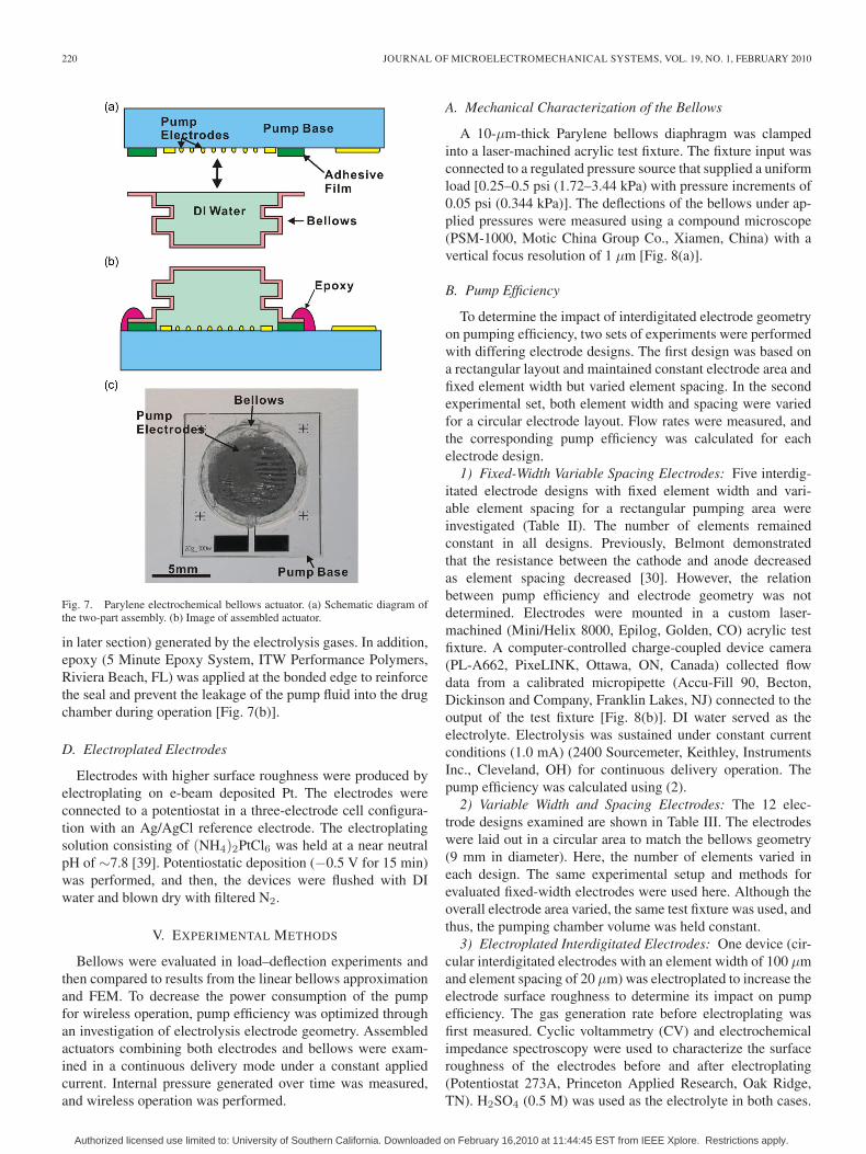
The assembly process of the electrochemical actuator isshown in Fig. 7. The bellows half of the actuator was first filledwith DI water, degassed in a vacuum oven (V0914 vacuumoven, Lindberg/Blue, Asheville, NC), and attached to the pumpbase using a laser cut (Mini/Helix 8000, Epilog, Golden, CO)double-sided pressure-sensitive adhesive film (Tape 415, 3M,St. Paul, MN) [Fig. 7(a)]. A metal ring (∼50 g) was appliedon the bonding region for 24 h as a uniform load to enable amaximum bonding strength between the bellows and the glasssubstrate. The maximum tensile bonding strength of the tape isaround 70–200 psi (0.48–1.38 MPa) which is far greater thanthe maximum bellows internal pressure of 0.5 psi (data shown
Authorized licensed use limited to: University of Southern California. Downloaded on February 16,2010 at 11:44:45 EST from IEEE Xplore. Restrictions apply.
220 JOURNAL OF MICROELECTROMECHANICAL SYSTEMS, VOL. 19, NO. 1, FEBRUARY 2010
Fig. 7. Parylene electrochemical bellows actuator. (a) Schematic diagram ofthe two-part assembly. (b) Image of assembled actuator.
in later section) generated by the electrolysis gases. In addition,epoxy (5 Minute Epoxy System, ITW Performance Polymers,Riviera Beach, FL) was applied at the bonded edge to reinforcethe seal and prevent the leakage of the pump fluid into the drugchamber during operation [Fig. 7(b)].
D. Electroplated Electrodes
Electrodes with higher surface roughness were produced byelectroplating on e-beam deposited Pt. The electrodes wereconnected to a potentiostat in a three-electrode cell configura-tion with an Ag/AgCl reference electrode. The electroplatingsolution consisting of (NH4)2PtCl6 was held at a near neutralpH of ∼7.8 [39]. Potentiostatic deposition (−0.5 V for 15 min)was performed, and then, the devices were flushed with DIwater and blown dry with filtered N2.
V. EXPERIMENTAL METHODS
Bellows were evaluated in load–deflection experiments andthen compared to results from the linear bellows approximationand FEM. To decrease the power consumption of the pumpfor wireless operation, pump efficiency was optimized throughan investigation of electrolysis electrode geometry. Assembledactuators combining both electrodes and bellows were exam-ined in a continuous delivery mode under a constant appliedcurrent. Internal pressure generated over time was measured,and wireless operation was performed.
A. Mechanical Characterization of the Bellows
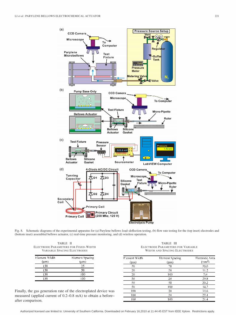
A 10-μm-thick Parylene bellows diaphragm was clampedinto a laser-machined acrylic test fixture. The fixture input wasconnected to a regulated pressure source that supplied a uniformload [0.25–0.5 psi (1.72–3.44 kPa) with pressure increments of0.05 psi (0.344 kPa)]. The deflections of the bellows under ap-plied pressures were measured using a compound microscope(PSM-1000, Motic China Group Co., Xiamen, China) with avertical focus resolution of 1 μm [Fig. 8(a)].
B. Pump Efficiency
To determine the impact of interdigitated electrode geometryon pumping efficiency, two sets of experiments were performedwith differing electrode designs. The first design was based ona rectangular layout and maintained constant electrode area andfixed element width but varied element spacing. In the secondexperimental set, both element width and spacing were variedfor a circular electrode layout. Flow rates were measured, andthe corresponding pump efficiency was calculated for eachelectrode design.
1) Fixed-Width Variable Spacing Electrodes: Five interdig-itated electrode designs with fixed element width and vari-able element spacing for a rectangular pumping area wereinvestigated (Table II). The number of elements remainedconstant in all designs. Previously, Belmont demonstratedthat the resistance between the cathode and anode decreasedas element spacing decreased [30]. However, the relationbetween pump efficiency and electrode geometry was notdetermined. Electrodes were mounted in a custom laser-machined (Mini/Helix 8000, Epilog, Golden, CO) acrylic testfixture. A computer-controlled charge-coupled device camera(PL-A662, PixeLINK, Ottawa, ON, Canada) collected flowdata from a calibrated micropipette (Accu-Fill 90, Becton,Dickinson and Company, Franklin Lakes, NJ) connected to theoutput of the test fixture [Fig. 8(b)]. DI water served as theelectrolyte. Electrolysis was sustained under constant currentconditions (1.0 mA) (2400 Sourcemeter, Keithley, InstrumentsInc., Cleveland, OH) for continuous delivery operation. Thepump efficiency was calculated using (2).
2) Variable Width and Spacing Electrodes: The 12 elec-trode designs examined are shown in Table III. The electrodeswere laid out in a circular area to match the bellows geometry(9 mm in diameter). Here, the number of elements varied ineach design. The same experimental setup and methods forevaluated fixed-width electrodes were used here. Although theoverall electrode area varied, the same test fixture was used, andthus, the pumping chamber volume was held constant.
3) Electroplated Interdigitated Electrodes: One device (cir-cular interdigitated electrodes with an element width of 100 μmand element spacing of 20 μm) was electroplated to increase theelectrode surface roughness to determine its impact on pumpefficiency. The gas generation rate before electroplating wasfirst measured. Cyclic voltammetry (CV) and electrochemicalimpedance spectroscopy were used to characterize the surfaceroughness of the electrodes before and after electroplating(Potentiostat 273A, Princeton Applied Research, Oak Ridge,TN). H2SO4 (0.5 M) was used as the electrolyte in both cases.
Authorized licensed use limited to: University of Southern California. Downloaded on February 16,2010 at 11:44:45 EST from IEEE Xplore. Restrictions apply.
LI et al.: PARYLENE BELLOWS ELECTROCHEMICAL ACTUATOR 221
Fig. 8. Schematic diagrams of the experimental apparatus for (a) Parylene bellows load–deflection testing, (b) flow rate testing for the (top inset) electrodes and(bottom inset) assembled bellows actuator, (c) real-time pressure monitoring, and (d) wireless operation.
TABLE IIELECTRODE PARAMETERS FOR FIXED-WIDTH
VARIABLE SPACING ELECTRODES
Finally, the gas generation rate of the electroplated device wasmeasured (applied current of 0.2–0.8 mA) to obtain a before–after comparison.
TABLE IIIELECTRODE PARAMETERS FOR VARIABLE
WIDTH AND SPACING ELECTRODES
Authorized licensed use limited to: University of Southern California. Downloaded on February 16,2010 at 11:44:45 EST from IEEE Xplore. Restrictions apply.
222 JOURNAL OF MICROELECTROMECHANICAL SYSTEMS, VOL. 19, NO. 1, FEBRUARY 2010
C. Flow Rate
Assembled bellows actuators were evaluated using the sametest fixture and mounted as shown in Fig. 8(b). Fluid waspumped under a constant current (0.2–1.0 mA), and the asso-ciated pump efficiency was calculated from (2).
D. Real-Time Pressure Measurement
Real-time measurements of electrolysis chamber pressurewere collected at different currents to characterize actuatorperformance. Pressure was also tracked for on–off operationof the pump. A pressure sensor (ASDX015D44R, HoneywellInternational Inc., Morristown, NJ) with a response time of8 ms was connected to the outlet of the test fixture, and itsoutput signal was fed into a data acquisition unit (LabVIEW 7.1with 2700 DAQ, Keithley Instruments Inc., Cleveland, OH)[Fig. 8(c)].
E. Wireless Operation
A wireless inductive power transfer system specifically de-veloped for biomedical implants was adapted for use with ouractuator (2 MHz) [Fig. 8(d)] [40]. RF power was transferredbetween a primary and a secondary coil; only interdigitatedelectrodes were attached to the secondary coil through a four-diode ac/dc rectifying circuit. Operation with two types ofcoils was performed: 1) a hand-wound Litz wire coil and2) a coil patterned on a printed circuit board (PCB). Rectangularinterdigitated electrodes with an element width of 150 μm andspacing of 100 μm were used.
VI. RESULTS AND DISCUSSION
A. Mechanical Characterization of the Bellows
Bellows were selected as the actuator diaphragm for itssuperior deflection with lower material stress based on non-linear FEM results. Critical stress points were identified atthe bottom edge of the bellows [Fig. 3(b)]. Bellows achievedgreater deflection compared to corrugated membranes (1.5 mmversus 0.8 mm for 10-μm-thick membranes) under a 0.5-psi(3.44-kPa) applied pressure. The maximum stress imposed onthe bellows under the 0.5-psi (3.44-kPa) applied pressure was61.8 MPa which is less than the tensile strength (68.9 MPa) buthigher than the yield strength (55.2 MPa) of Parylene. However,these critical stress sites are limited to small regions, and thebellows is expected to survive pressurized conditions that ariseduring electrolysis loading.
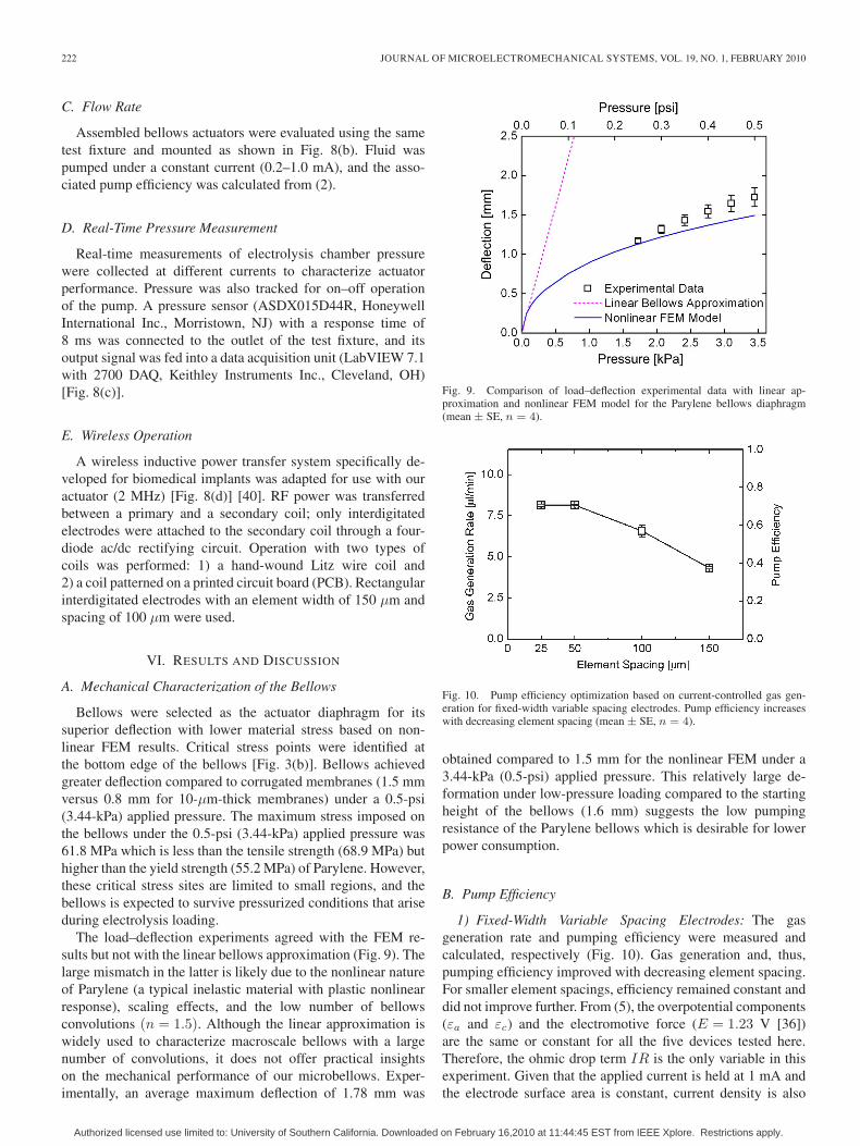
The load–deflection experiments agreed with the FEM re-sults but not with the linear bellows approximation (Fig. 9). Thelarge mismatch in the latter is likely due to the nonlinear natureof Parylene (a typical inelastic material with plastic nonlinearresponse), scaling effects, and the low number of bellowsconvolutions (n = 1.5). Although the linear approximation iswidely used to characterize macroscale bellows with a largenumber of convolutions, it does not offer practical insightson the mechanical performance of our microbellows. Exper-imentally, an average maximum deflection of 1.78 mm was
Fig. 9. Comparison of load–deflection experimental data with linear ap-proximation and nonlinear FEM model for the Parylene bellows diaphragm(mean ± SE, n = 4).
Fig. 10. Pump efficiency optimization based on current-controlled gas gen-eration for fixed-width variable spacing electrodes. Pump efficiency increaseswith decreasing element spacing (mean ± SE, n = 4).
obtained compared to 1.5 mm for the nonlinear FEM under a3.44-kPa (0.5-psi) applied pressure. This relatively large de-formation under low-pressure loading compared to the startingheight of the bellows (1.6 mm) suggests the low pumpingresistance of the Parylene bellows which is desirable for lowerpower consumption.
B. Pump Efficiency
1) Fixed-Width Variable Spacing Electrodes: The gasgeneration rate and pumping efficiency were measured andcalculated, respectively (Fig. 10). Gas generation and, thus,pumping efficiency improved with decreasing element spacing.For smaller element spacings, efficiency remained constant anddid not improve further. From (5), the overpotential components(εa and εc) and the electromotive force (E = 1.23 V [36])are the same or constant for all the five devices tested here.Therefore, the ohmic drop term IR is the only variable in thisexperiment. Given that the applied current is held at 1 mA andthe electrode surface area is constant, current density is also
Authorized licensed use limited to: University of Southern California. Downloaded on February 16,2010 at 11:44:45 EST from IEEE Xplore. Restrictions apply.
LI et al.: PARYLENE BELLOWS ELECTROCHEMICAL ACTUATOR 223
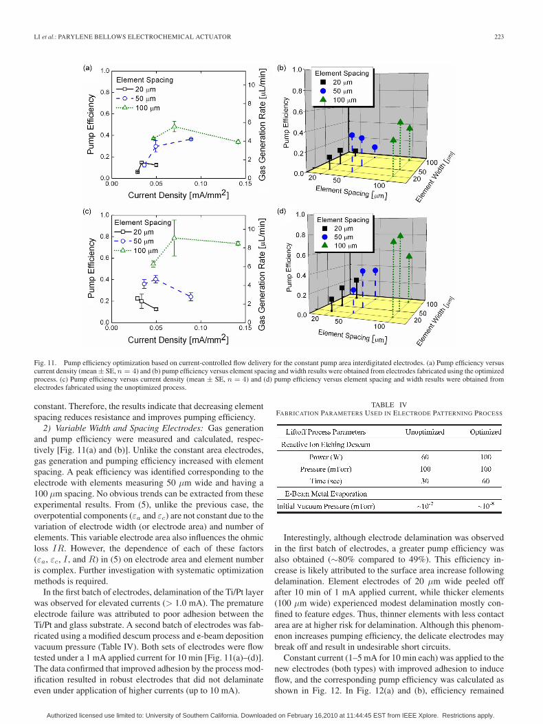
Fig. 11. Pump efficiency optimization based on current-controlled flow delivery for the constant pump area interdigitated electrodes. (a) Pump efficiency versuscurrent density (mean ± SE, n = 4) and (b) pump efficiency versus element spacing and width results were obtained from electrodes fabricated using the optimizedprocess. (c) Pump efficiency versus current density (mean ± SE, n = 4) and (d) pump efficiency versus element spacing and width results were obtained fromelectrodes fabricated using the unoptimized process.
constant. Therefore, the results indicate that decreasing elementspacing reduces resistance and improves pumping efficiency.
2) Variable Width and Spacing Electrodes: Gas generationand pump efficiency were measured and calculated, respec-tively [Fig. 11(a) and (b)]. Unlike the constant area electrodes,gas generation and pumping efficiency increased with elementspacing. A peak efficiency was identified corresponding to theelectrode with elements measuring 50 μm wide and having a100 μm spacing. No obvious trends can be extracted from theseexperimental results. From (5), unlike the previous case, theoverpotential components (εa and εc) are not constant due to thevariation of electrode width (or electrode area) and number ofelements. This variable electrode area also influences the ohmicloss IR. However, the dependence of each of these factors(εa, εc, I , and R) in (5) on electrode area and element numberis complex. Further investigation with systematic optimizationmethods is required.
In the first batch of electrodes, delamination of the Ti/Pt layerwas observed for elevated currents (> 1.0 mA). The prematureelectrode failure was attributed to poor adhesion between theTi/Pt and glass substrate. A second batch of electrodes was fab-ricated using a modified descum process and e-beam depositionvacuum pressure (Table IV). Both sets of electrodes were flowtested under a 1 mA applied current for 10 min [Fig. 11(a)–(d)].The data confirmed that improved adhesion by the process mod-ification resulted in robust electrodes that did not delaminateeven under application of higher currents (up to 10 mA).
TABLE IVFABRICATION PARAMETERS USED IN ELECTRODE PATTERNING PROCESS
Interestingly, although electrode delamination was observedin the first batch of electrodes, a greater pump efficiency wasalso obtained (∼80% compared to 49%). This efficiency in-crease is likely attributed to the surface area increase followingdelamination. Element electrodes of 20 μm wide peeled offafter 10 min of 1 mA applied current, while thicker elements(100 μm wide) experienced modest delamination mostly con-fined to feature edges. Thus, thinner elements with less contactarea are at higher risk for delamination. Although this phenom-enon increases pumping efficiency, the delicate electrodes maybreak off and result in undesirable short circuits.
Constant current (1–5 mA for 10 min each) was applied to thenew electrodes (both types) with improved adhesion to induceflow, and the corresponding pump efficiency was calculated asshown in Fig. 12. In Fig. 12(a) and (b), efficiency remained
Authorized licensed use limited to: University of Southern California. Downloaded on February 16,2010 at 11:44:45 EST from IEEE Xplore. Restrictions apply.
224 JOURNAL OF MICROELECTROMECHANICAL SYSTEMS, VOL. 19, NO. 1, FEBRUARY 2010
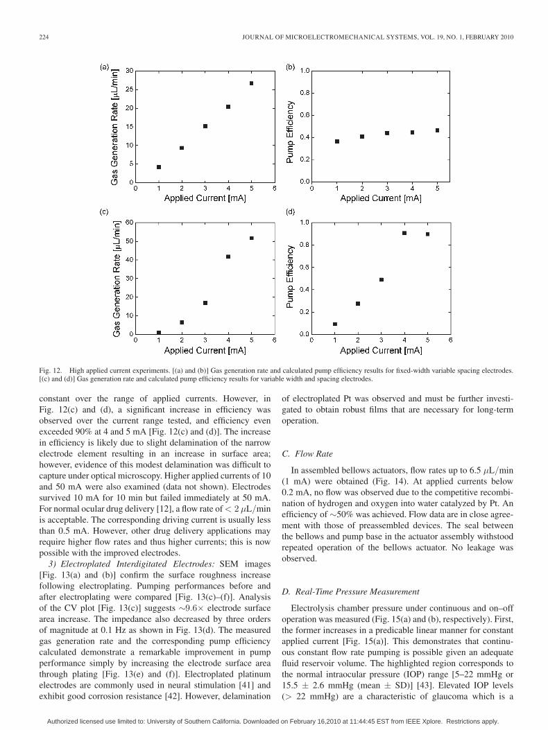
Fig. 12. High applied current experiments. [(a) and (b)] Gas generation rate and calculated pump efficiency results for fixed-width variable spacing electrodes.[(c) and (d)] Gas generation rate and calculated pump efficiency results for variable width and spacing electrodes.
constant over the range of applied currents. However, inFig. 12(c) and (d), a significant increase in efficiency wasobserved over the current range tested, and efficiency evenexceeded 90% at 4 and 5 mA [Fig. 12(c) and (d)]. The increasein efficiency is likely due to slight delamination of the narrowelectrode element resulting in an increase in surface area;however, evidence of this modest delamination was difficult tocapture under optical microscopy. Higher applied currents of 10and 50 mA were also examined (data not shown). Electrodessurvived 10 mA for 10 min but failed immediately at 50 mA.For normal ocular drug delivery [12], a flow rate of < 2 μL/minis acceptable. The corresponding driving current is usually lessthan 0.5 mA. However, other drug delivery applications mayrequire higher flow rates and thus higher currents; this is nowpossible with the improved electrodes.
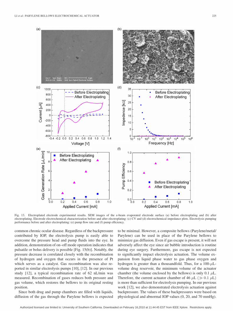
3) Electroplated Interdigitated Electrodes: SEM images[Fig. 13(a) and (b)] confirm the surface roughness increasefollowing electroplating. Pumping performances before andafter electroplating were compared [Fig. 13(c)–(f)]. Analysisof the CV plot [Fig. 13(c)] suggests ∼9.6× electrode surfacearea increase. The impedance also decreased by three ordersof magnitude at 0.1 Hz as shown in Fig. 13(d). The measuredgas generation rate and the corresponding pump efficiencycalculated demonstrate a remarkable improvement in pumpperformance simply by increasing the electrode surface areathrough plating [Fig. 13(e) and (f)]. Electroplated platinumelectrodes are commonly used in neural stimulation [41] andexhibit good corrosion resistance [42]. However, delamination
of electroplated Pt was observed and must be further investi-gated to obtain robust films that are necessary for long-termoperation.
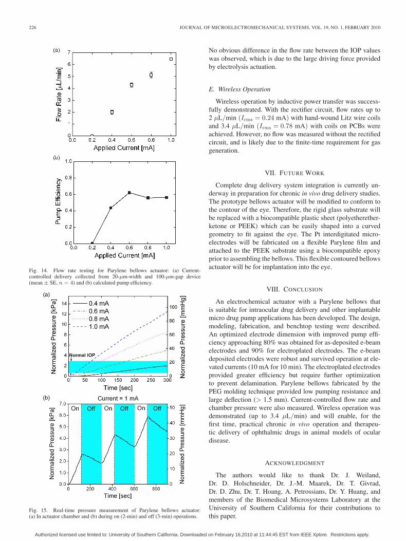
C. Flow Rate
In assembled bellows actuators, flow rates up to 6.5 μL/min(1 mA) were obtained (Fig. 14). At applied currents below0.2 mA, no flow was observed due to the competitive recombi-nation of hydrogen and oxygen into water catalyzed by Pt. Anefficiency of ∼50% was achieved. Flow data are in close agree-ment with those of preassembled devices. The seal betweenthe bellows and pump base in the actuator assembly withstoodrepeated operation of the bellows actuator. No leakage wasobserved.
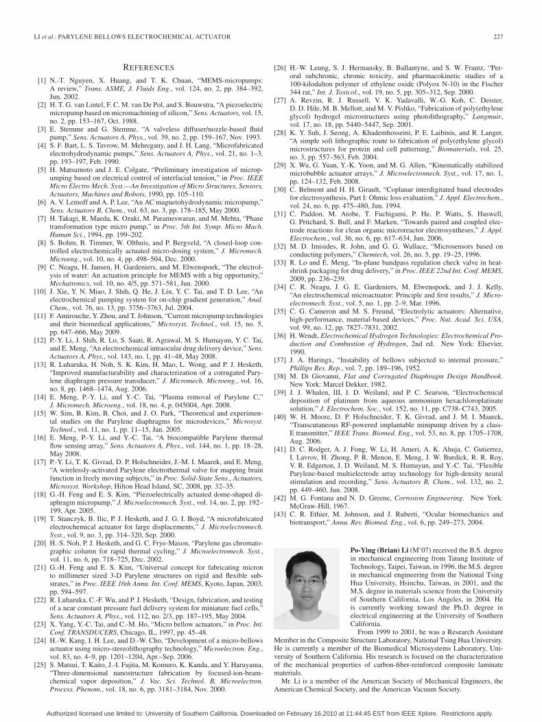
D. Real-Time Pressure Measurement
Electrolysis chamber pressure under continuous and on–offoperation was measured (Fig. 15(a) and (b), respectively). First,the former increases in a predicable linear manner for constantapplied current [Fig. 15(a)]. This demonstrates that continu-ous constant flow rate pumping is possible given an adequatefluid reservoir volume. The highlighted region corresponds tothe normal intraocular pressure (IOP) range [5–22 mmHg or15.5 ± 2.6 mmHg (mean ± SD)] [43]. Elevated IOP levels(> 22 mmHg) are a characteristic of glaucoma which is a
Authorized licensed use limited to: University of Southern California. Downloaded on February 16,2010 at 11:44:45 EST from IEEE Xplore. Restrictions apply.
LI et al.: PARYLENE BELLOWS ELECTROCHEMICAL ACTUATOR 225
Fig. 13. Electroplated electrode experimental results. SEM images of the e-beam evaporated electrode surface (a) before electroplating and (b) afterelectroplating. Electrode electrochemical characterization before and after electroplating: (c) CV and (d) electrochemical impedance plots. Electrolysis pumpingperformance before and after electroplating: (e) pump flow rate and (f) pump efficiency.
common chronic ocular disease. Regardless of the backpressurecontributed by IOP, the electrolysis pump is easily able toovercome the pressure head and pump fluids into the eye. Inaddition, demonstration of on–off mode operation indicates thatpulsatile or bolus delivery is possible [Fig. 15(b)]. Notably, thepressure decrease is correlated closely with the recombinationof hydrogen and oxygen that occurs in the presence of Ptwhich serves as a catalyst. Gas recombination was also re-ported in similar electrolysis pumps [10], [12]. In our previousstudy [12], a typical recombination rate of 62 nL/min wasmeasured. Recombination of gases reduces both pressure andgas volume, which restores the bellows to its original restingposition.
Since both drug and pump chambers are filled with liquids,diffusion of the gas through the Parylene bellows is expected
to be minimal. However, a composite bellows (Parylene/metal/Parylene) can be used in place of the Parylene bellows tominimize gas diffusion. Even if gas escape is present, it will notadversely affect the eye since air bubble introduction is routineduring eye surgery. Furthermore, gas escape is not expectedto significantly impact electrolysis actuation. The volume ex-pansion from liquid phase water to gas phase oxygen andhydrogen is greater than a thousandfold. Thus, for a 100-μL-volume drug reservoir, the minimum volume of the actuatorchamber (the volume enclosed by the bellows) is only 0.1 μL.Therefore, the current actuator chamber of 46 μL (� 0.1 μL)is more than sufficient for electrolysis pumping. In our previouswork [12], we also demonstrated electrolysis actuation againstbackpressure. The values of these backpressures were based onphysiological and abnormal IOP values (0, 20, and 70 mmHg).
Authorized licensed use limited to: University of Southern California. Downloaded on February 16,2010 at 11:44:45 EST from IEEE Xplore. Restrictions apply.
226 JOURNAL OF MICROELECTROMECHANICAL SYSTEMS, VOL. 19, NO. 1, FEBRUARY 2010
Fig. 14. Flow rate testing for Parylene bellows actuator: (a) Current-controlled delivery collected from 20-μm-width and 100-μm-gap device(mean ± SE, n = 4) and (b) calculated pump efficiency.
Fig. 15. Real-time pressure measurement of Parylene bellows actuator:(a) In actuator chamber and (b) during on (2-min) and off (3-min) operations.
No obvious difference in the flow rate between the IOP valueswas observed, which is due to the large driving force providedby electrolysis actuation.
E. Wireless Operation
Wireless operation by inductive power transfer was success-fully demonstrated. With the rectifier circuit, flow rates up to2 μL/min (Irms = 0.24 mA) with hand-wound Litz wire coilsand 3.4 μL/min (Irms = 0.78 mA) with coils on PCBs wereachieved. However, no flow was measured without the rectifiedcircuit, and is likely due to the finite-time requirement for gasgeneration.
VII. FUTURE WORK
Complete drug delivery system integration is currently un-derway in preparation for chronic in vivo drug delivery studies.The prototype bellows actuator will be modified to conform tothe contour of the eye. Therefore, the rigid glass substrate willbe replaced with a biocompatible plastic sheet (polyetherether-ketone or PEEK) which can be easily shaped into a curvedgeometry to fit against the eye. The Pt interdigitated micro-electrodes will be fabricated on a flexible Parylene film andattached to the PEEK substrate using a biocompatible epoxyprior to assembling the bellows. This flexible contoured bellowsactuator will be for implantation into the eye.
VIII. CONCLUSION
An electrochemical actuator with a Parylene bellows thatis suitable for intraocular drug delivery and other implantablemicro drug pump applications has been developed. The design,modeling, fabrication, and benchtop testing were described.An optimized electrode dimension with improved pump effi-ciency approaching 80% was obtained for as-deposited e-beamelectrodes and 90% for electroplated electrodes. The e-beamdeposited electrodes were robust and survived operation at ele-vated currents (10 mA for 10 min). The electroplated electrodesprovided greater efficiency but require further optimizationto prevent delamination. Parylene bellows fabricated by thePEG molding technique provided low pumping resistance andlarge deflection (> 1.5 mm). Current-controlled flow rate andchamber pressure were also measured. Wireless operation wasdemonstrated (up to 3.4 μL/min) and will enable, for thefirst time, practical chronic in vivo operation and therapeu-tic delivery of ophthalmic drugs in animal models of oculardisease.
ACKNOWLEDGMENT
The authors would like to thank Dr. J. Weiland,Dr. D. Holschneider, Dr. J.-M. Maarek, Dr. T. Givrad,Dr. D. Zhu, Dr. T. Hoang, A. Petrossians, Dr. Y. Huang, andmembers of the Biomedical Microsystems Laboratory at theUniversity of Southern California for their contributions tothis paper.
Authorized licensed use limited to: University of Southern California. Downloaded on February 16,2010 at 11:44:45 EST from IEEE Xplore. Restrictions apply.
LI et al.: PARYLENE BELLOWS ELECTROCHEMICAL ACTUATOR 227
REFERENCES
[1] N.-T. Nguyen, X. Huang, and T. K. Chuan, “MEMS-micropumps:A review,” Trans. ASME, J. Fluids Eng., vol. 124, no. 2, pp. 384–392,Jun. 2002.
[2] H. T. G. van Lintel, F. C. M. van De Pol, and S. Bouwstra, “A piezoelectricmicropump based on micromachining of silicon,” Sens. Actuators, vol. 15,no. 2, pp. 153–167, Oct. 1988.
[3] E. Stemme and G. Stemme, “A valveless diffuser/nozzle-based fluidpump,” Sens. Actuators A, Phys., vol. 39, no. 2, pp. 159–167, Nov. 1993.
[4] S. F. Bart, L. S. Tavrow, M. Mehregany, and J. H. Lang, “Microfabricatedelectrohydrodynamic pumps,” Sens. Actuators A, Phys., vol. 21, no. 1–3,pp. 193–197, Feb. 1990.
[5] H. Matsumoto and J. E. Colgate, “Preliminary investigation of microp-umping based on electrical control of interfacial tension,” in Proc. IEEEMicro Electro Mech. Syst.—An Investigation of Micro Structures, Sensors,Actuators, Machines and Robots, 1990, pp. 105–110.
[6] A. V. Lemoff and A. P. Lee, “An AC magnetohydrodynamic micropump,”Sens. Actuators B, Chem., vol. 63, no. 3, pp. 178–185, May 2000.
[7] H. Takagi, R. Maeda, K. Ozaki, M. Parameswaran, and M. Mehta, “Phasetransformation type micro pump,” in Proc. 5th Int. Symp. Micro Mach.Human Sci., 1994, pp. 199–202.
[8] S. Bohm, B. Timmer, W. Olthuis, and P. Bergveld, “A closed-loop con-trolled electrochemically actuated micro-dosing system,” J. Micromech.Microeng., vol. 10, no. 4, pp. 498–504, Dec. 2000.
[9] C. Neagu, H. Jansen, H. Gardeniers, and M. Elwenspoek, “The electrol-ysis of water: An actuation principle for MEMS with a big opportunity,”Mechatronics, vol. 10, no. 4/5, pp. 571–581, Jun. 2000.
[10] J. Xie, Y. N. Miao, J. Shih, Q. He, J. Liu, Y. C. Tai, and T. D. Lee, “Anelectrochemical pumping system for on-chip gradient generation,” Anal.Chem., vol. 76, no. 13, pp. 3756–3763, Jul. 2004.
[11] F. Amirouche, Y. Zhou, and T. Johnson, “Current micropump technologiesand their biomedical applications,” Microsyst. Technol., vol. 15, no. 5,pp. 647–666, May 2009.
[12] P.-Y. Li, J. Shih, R. Lo, S. Saati, R. Agrawal, M. S. Humayun, Y. C. Tai,and E. Meng, “An electrochemical intraocular drug delivery device,” Sens.Actuators A, Phys., vol. 143, no. 1, pp. 41–48, May 2008.
[13] R. Luharuka, H. Noh, S. K. Kim, H. Mao, L. Wong, and P. J. Hesketh,“Improved manufacturability and characterization of a corrugated Pary-lene diaphragm pressure transducer,” J. Micromech. Microeng., vol. 16,no. 8, pp. 1468–1474, Aug. 2006.
[14] E. Meng, P.-Y. Li, and Y.-C. Tai, “Plasma removal of Parylene C,”J. Micromech. Microeng., vol. 18, no. 4, p. 045004, Apr. 2008.
[15] W. Sim, B. Kim, B. Choi, and J. O. Park, “Theoretical and experimen-tal studies on the Parylene diaphragms for microdevices,” Microsyst.Technol., vol. 11, no. 1, pp. 11–15, Jan. 2005.
[16] E. Meng, P.-Y. Li, and Y.-C. Tai, “A biocompatible Parylene thermalflow sensing array,” Sens. Actuators A, Phys., vol. 144, no. 1, pp. 18–28,May 2008.
[17] P.-Y. Li, T. K. Givrad, D. P. Holschneider, J.-M. I. Maarek, and E. Meng,“A wirelessly-activated Parylene electrothermal valve for mapping brainfunction in freely moving subjects,” in Proc. Solid-State Sens., Actuators,Microsyst. Workshop, Hilton Head Island, SC, 2008, pp. 32–35.
[18] G.-H. Feng and E. S. Kim, “Piezoelectrically actuated dome-shaped di-aphragm micropump,” J. Microelectromech. Syst., vol. 14, no. 2, pp. 192–199, Apr. 2005.
[19] T. Stanczyk, B. Ilic, P. J. Hesketh, and J. G. I. Boyd, “A microfabricatedelectrochemical actuator for large displacements,” J. Microelectromech.Syst., vol. 9, no. 3, pp. 314–320, Sep. 2000.
[20] H.-S. Noh, P. J. Hesketh, and G. C. Frye-Mason, “Parylene gas chromato-graphic column for rapid thermal cycling,” J. Microelectromech. Syst.,vol. 11, no. 6, pp. 718–725, Dec. 2002.
[21] G.-H. Feng and E. S. Kim, “Universal concept for fabricating micronto millimeter sized 3-D Parylene structures on rigid and flexible sub-strates,” in Proc. IEEE 16th Annu. Int. Conf. MEMS, Kyoto, Japan, 2003,pp. 594–597.
[22] R. Luharuka, C.-F. Wu, and P. J. Hesketh, “Design, fabrication, and testingof a near constant pressure fuel delivery system for miniature fuel cells,”Sens. Actuators A, Phys., vol. 112, no. 2/3, pp. 187–195, May 2004.
[23] X. Yang, Y.-C. Tai, and C.-M. Ho, “Micro bellow actuators,” in Proc. Int.Conf. TRANSDUCERS, Chicago, IL, 1997, pp. 45–48.
[24] H.-W. Kang, I. H. Lee, and D.-W. Cho, “Development of a micro-bellowsactuator using micro-stereolithography technology,” Microelectron. Eng.,vol. 83, no. 4–9, pp. 1201–1204, Apr.–Sep. 2006.
[25] S. Matsui, T. Kaito, J.-I. Fujita, M. Komuro, K. Kanda, and Y. Haruyama,“Three-dimensional nanostructure fabrication by focused-ion-beam-chemical vapor deposition,” J. Vac. Sci. Technol. B, Microelectron.Process. Phenom., vol. 18, no. 6, pp. 3181–3184, Nov. 2000.
[26] H.-W. Leung, S. J. Hermansky, B. Ballantyne, and S. W. Frantz, “Per-oral subchronic, chronic toxicity, and pharmacokinetic studies of a100-kilodalton polymer of ethylene oxide (Polyox N-10) in the Fischer344 rat,” Int. J. Toxicol., vol. 19, no. 5, pp. 305–312, Sep. 2000.
[27] A. Revzin, R. J. Russell, V. K. Yadavalli, W.-G. Koh, C. Deister,D. D. Hile, M. B. Mellott, and M. V. Pishko, “Fabrication of poly(ethyleneglycol) hydrogel microstructures using photolithography,” Langmuir,vol. 17, no. 18, pp. 5440–5447, Sep. 2001.
[28] K. Y. Suh, J. Seong, A. Khademhosseini, P. E. Laibinis, and R. Langer,“A simple soft lithographic route to fabrication of poly(ethylene glycol)microstructures for protein and cell patterning,” Biomaterials, vol. 25,no. 3, pp. 557–563, Feb. 2004.
[29] X. Wu, G. Yuan, Y.-K. Yoon, and M. G. Allen, “Kinematically stabilizedmicrobubble actuator arrays,” J. Microelectromech. Syst., vol. 17, no. 1,pp. 124–132, Feb. 2008.
[30] C. Belmont and H. H. Girault, “Coplanar interdigitated band electrodesfor electrosynthesis, Part I: Ohmic loss evaluation,” J. Appl. Electrochem.,vol. 24, no. 6, pp. 475–480, Jun. 1994.
[31] C. Paddon, M. Atobe, T. Fuchigami, P. He, P. Watts, S. Haswell,G. Pritchard, S. Bull, and F. Marken, “Towards paired and coupled elec-trode reactions for clean organic microreactor electrosyntheses,” J. Appl.Electrochem., vol. 36, no. 6, pp. 617–634, Jun. 2006.
[32] M. D. Imisides, R. John, and G. G. Wallace, “Microsensors based onconducting polymers,” Chemtech, vol. 26, no. 5, pp. 19–25, 1996.
[33] R. Lo and E. Meng, “In-plane bandpass regulation check valve in heat-shrink packaging for drug delivery,” in Proc. IEEE 22nd Int. Conf. MEMS,2009, pp. 236–239.
[34] C. R. Neagu, J. G. E. Gardeniers, M. Elwenspoek, and J. J. Kelly,“An electrochemical microactuator: Principle and first results,” J. Micro-electromech. Syst., vol. 5, no. 1, pp. 2–9, Mar. 1996.
[35] C. G. Cameron and M. S. Freund, “Electrolytic actuators: Alternative,high-performance, material-based devices,” Proc. Nat. Acad. Sci. USA,vol. 99, no. 12, pp. 7827–7831, 2002.
[36] H. Wendt, Electrochemical Hydrogen Technologies: Electrochemical Pro-duction and Combustion of Hydrogen, 2nd ed. New York: Elsevier,1990.
[37] J. A. Haringx, “Instability of bellows subjected to internal pressure,”Phillips Res. Rep., vol. 7, pp. 189–196, 1952.
[38] M. Di Giovanni, Flat and Corrugated Diaphragm Design Handbook.New York: Marcel Dekker, 1982.
[39] J. J. Whalen, III, J. D. Weiland, and P. C. Searson, “Electrochemicaldeposition of platinum from aqueous ammonium hexachloroplatinatesolution,” J. Electrochem. Soc., vol. 152, no. 11, pp. C738–C743, 2005.
[40] W. H. Moore, D. P. Holschneider, T. K. Givrad, and J. M. I. Maarek,“Transcutaneous RF-powered implantable minipump driven by a class-E transmitter,” IEEE Trans. Biomed. Eng., vol. 53, no. 8, pp. 1705–1708,Aug. 2006.
[41] D. C. Rodger, A. J. Fong, W. Li, H. Ameri, A. K. Ahuja, C. Gutierrez,I. Lavrov, H. Zhong, P. R. Menon, E. Meng, J. W. Burdick, R. R. Roy,V. R. Edgerton, J. D. Weiland, M. S. Humayun, and Y.-C. Tai, “FlexibleParylene-based multielectrode array technology for high-density neuralstimulation and recording,” Sens. Actuators B, Chem., vol. 132, no. 2,pp. 449–460, Jun. 2008.
[42] M. G. Fontana and N. D. Greene, Corrosion Engineering. New York:McGraw-Hill, 1967.
[43] C. R. Ethier, M. Johnson, and J. Ruberti, “Ocular biomechanics andbiotransport,” Annu. Rev. Biomed. Eng., vol. 6, pp. 249–273, 2004.
Po-Ying (Brian) Li (M’07) received the B.S. degreein mechanical engineering from Tatung Institute ofTechnology, Taipei, Taiwan, in 1996, the M.S. degreein mechanical engineering from the National TsingHua University, Hsinchu, Taiwan, in 2001, and theM.S. degree in materials science from the Universityof Southern California, Los Angeles, in 2004. Heis currently working toward the Ph.D. degree inelectrical engineering at the University of SouthernCalifornia.
From 1999 to 2001, he was a Research AssistantMember in the Composite Structure Laboratory, National Tsing Hua University.He is currently a member of the Biomedical Microsystems Laboratory, Uni-versity of Southern California. His research is focused on the characterizationof the mechanical properties of carbon-fiber-reinforced composite laminatematerials.
Mr. Li is a member of the American Society of Mechanical Engineers, theAmerican Chemical Society, and the American Vacuum Society.
Authorized licensed use limited to: University of Southern California. Downloaded on February 16,2010 at 11:44:45 EST from IEEE Xplore. Restrictions apply.
228 JOURNAL OF MICROELECTROMECHANICAL SYSTEMS, VOL. 19, NO. 1, FEBRUARY 2010
Roya Sheybani received the B.S. degree in bio-medical engineering from the University of SouthernCalifornia (USC), Los Angeles, in 2008, where sheis currently working toward the M.S. degree in bio-medical engineering.
Since 2008, she has been with the BiomedicalMicrosystems Laboratory, University of SouthernCalifornia, as a Student Researcher. Her research in-cludes the characterization of electrothermal valvesand electrolysis-based drug delivery devices. Her re-search interests include ocular microelectromechan-
ical devices and drug delivery systems.Ms. Sheybani is a member of Tau Beta Pi and the Associated Students of
Biomedical Engineering. She was a recipient of the USC Women in Scienceand Engineering Undergraduate Research Grant.
Christian A. Gutierrez received B.S. degrees inelectrical engineering and business economics andmanagement and the M.S. degree in electrical engi-neering from the California Institute of Technology(Caltech), Pasadena, in 2005 and 2006, respec-tively. He is currently working toward the Ph.D.degree in biomedical engineering (under fellowship)at the University of Southern California (USC),Los Angeles.
He currently works at the National Science Foun-dation’s Biomimetic Microelectronic Systems Engi-
neering Research Center, where he is a Copresident of the student leadershipcouncil. His past research was carried out in the Caltech Micromaching Labo-ratory and was focused on identifying, analyzing, and implementing power har-vesting and storage circuitry for microelectromechanical-systems-based powerharvesting devices. He is currently conducting research toward the developmentof novel micro- and nanotechnologies for biomedical applications. His specificresearch is focused on the development of retinal prosthesis technologies torestore sight to the blind.
Mr. Gutierrez was a recipient of the Caltech Presidential Scholarship and iscurrently a Bill Gates Millennium Scholar. He is also a recipient of the USCViterbi School of Engineering Kunzel Fellowship.
Jonathan T. W. Kuo received the B.S. degree inbioengineering from the University of California,San Diego, in 2007. He is currently working towardthe Ph.D. degree in biomedical engineering at theUniversity of Southern California, Los Angeles.
Ellis Meng (M’02–SM’09) received the B.S. degreein engineering and applied science and the M.S.and Ph.D. degrees in electrical engineering fromthe California Institute of Technology (Caltech),Pasadena, in 1997, 1998, and 2003, respectively.
Since 2004, she has been an Assistant Professor inthe Department of Biomedical Engineering, Univer-sity of Southern California, Los Angeles. She cur-rently holds a joint appointment in the Ming HsiehDepartment of Electrical Engineering. Her researchinterests include bioMEMS, implantable biomedical
microdevices, microfluidics, multimodality integrated microsystems, and pack-aging. Currently, she is the Thrust Leader for Interface Technology and theAssociate Director of Education and Student Diversity Researcher at the Na-tional Science Foundation’s Biomimetic MicroElectronic Systems EngineeringResearch Center. She also holds the Viterbi Early Career Chair in the ViterbiSchool of Engineering.
Dr. Meng is a member of Tau Beta Pi, the Biomedical Engineering Society,the Society of Women Engineers, and the American Society for EngineeringEducation. She was a recipient of the Intel Women in Science and EngineeringScholarship, the Caltech Alumni Association Donald S. Clark Award, andthe Caltech Special Institute Fellowship. She has also received the NSFCAREER and Wallace H. Coulter Foundation Early Career TranslationalResearch Awards.
Authorized licensed use limited to: University of Southern California. Downloaded on February 16,2010 at 11:44:45 EST from IEEE Xplore. Restrictions apply.