A Packet Scheduling Algorithm for Max-Min Fairness …kasahara/paper/09/wktki09final.pdfA Packet...
17
A Packet Scheduling Algorithm for Max-Min Fairness in Multihop Wireless LANs Kensaku Wakuda a Shoji Kasahara a,∗ Yutaka Takahashi a Yoshinobu Kure b Eisaburo Itakura b a Graduate School of Informatics, Kyoto University 36-1 Yoshida-Honmachi, Sakyo-ku, Kyoto 606-8501, Japan b B2B Solutions Business Group, Sony Corporation 4-14-1 Asahi-cho, Atsugi-shi, Kanagawa 243-0014, Japan Abstract In this paper, we propose a probabilistic packet scheduling scheme achieving max- min fairness without changing the existing IEEE 802.11 medium access control (MAC) protocol. In the proposed scheme, packets at each wireless node are managed on a per-flow basis. When a wireless node is ready to send a packet, the packet scheduler of the node is likely to select the queue whose number of packets sent in a certain time is the smallest. If the selected queue has no packet, the node defers the transmission by a fixed duration. In order to verify the improvement in per-flow fairness, we evaluate the performance of the proposed scheme by ns-2. The numerical examples show that our proposed scheme achieves better per-flow fairness than the existing schemes in networks of not only chain topologies but also random topologies. Key words: IEEE 802.11 DCF, multihop communication, packet scheduling, throughput performance, max-min fairness 1 Introduction Recently, multihop wireless local area networks (LANs) have attracted consid- erable attention for next-generation networks supporting a large number of end users. Currently, the most prevalent wireless LAN standard is IEEE 802.11. The distributed coordination function (DCF) is a fundamental mechanism of ∗ Corresponding author. Tel: +81-75-753-5493; Fax: +81-75-753-3358. Email address: [email protected] (Shoji Kasahara). Preprint submitted to Elsevier 23 April 2009
Transcript of A Packet Scheduling Algorithm for Max-Min Fairness …kasahara/paper/09/wktki09final.pdfA Packet...

A Packet Scheduling Algorithm for Max-Min
Fairness in Multihop Wireless LANs
Kensaku Wakuda a Shoji Kasahara a,∗ Yutaka Takahashi a
Yoshinobu Kure b Eisaburo Itakura b
aGraduate School of Informatics, Kyoto University36-1 Yoshida-Honmachi, Sakyo-ku, Kyoto 606-8501, Japan
bB2B Solutions Business Group, Sony Corporation4-14-1 Asahi-cho, Atsugi-shi, Kanagawa 243-0014, Japan
Abstract
In this paper, we propose a probabilistic packet scheduling scheme achieving max-min fairness without changing the existing IEEE 802.11 medium access control(MAC) protocol. In the proposed scheme, packets at each wireless node are managedon a per-flow basis. When a wireless node is ready to send a packet, the packetscheduler of the node is likely to select the queue whose number of packets sentin a certain time is the smallest. If the selected queue has no packet, the nodedefers the transmission by a fixed duration. In order to verify the improvement inper-flow fairness, we evaluate the performance of the proposed scheme by ns-2. Thenumerical examples show that our proposed scheme achieves better per-flow fairnessthan the existing schemes in networks of not only chain topologies but also randomtopologies.
Key words: IEEE 802.11 DCF, multihop communication, packet scheduling,throughput performance, max-min fairness
1 Introduction
Recently, multihop wireless local area networks (LANs) have attracted consid-erable attention for next-generation networks supporting a large number of endusers. Currently, the most prevalent wireless LAN standard is IEEE 802.11.The distributed coordination function (DCF) is a fundamental mechanism of
∗ Corresponding author. Tel: +81-75-753-5493; Fax: +81-75-753-3358.Email address: [email protected] (Shoji Kasahara).
Preprint submitted to Elsevier 23 April 2009

the medium access control (MAC) protocol for IEEE 802.11, employing Car-rier Sense Multiple Access with Collision Avoidance (CSMA/CA). The IEEE802.11 DCF specifies random backoff algorithm, with which each wireless nodetransmits data in an autonomous-decentralized manner.
When the number of nodes increases, the overall throughput significantly de-grades due to the hidden-node problem. To resolve this problem, the four-way handshake by using Request-To-Send/Clear-To-Send (RTS/CTS) framesis available in IEEE 802.11. Because the four-way handshake was developedfor single-hop communications, however, it does not work well for multihopcommunications. The multihop wireless LANs have several issues to be tack-led such as routing, the guarantee of quality of service (QoS), security andfairness. In this paper, we focus on throughput unfairness, in which the end-to-end throughput of a packet flow degrades significantly with the increase inthe number of its transmission hops.
There is much literature for achieving per-flow fairness in multihop wirelessnetworks. Salem and Hubaux [11] focused on Spatial Time Division MultipleAccess (STDMA) [7] and proposed a MAC-level packet scheduling for wirelessmesh networks (WMNs), in which transmission rights are assigned to the linkssuch that the spatial reuse is maximized. Nandi and Gupta [6] reported theimprecise Extended Inter-Frame Space (EIFS) problem in which mismatchbetween the EIFS value and desired one causes unfairness and throughputdegradation. They proposed an enhanced carrier sensing (ECS), which differ-entiates the types of erroneous frames based on their lengths and defers thetransmission accordingly. Note that the above two methods require the modi-fication of the existing IEEE 802.11 MAC layer, which is not preferable fromthe deployment viewpoint.
Izumikawa et al. [4] proposed a per-flow packet scheduling scheme in whichpackets in a wireless node are classified into the packets originating from thenode and those forwarded from the other nodes. The transmission order ofpackets is determined in a round-robin fashion based on their source identifi-cations. Note that this scheme is designed for achieving the same throughputamong flows regardless of the number of hops. Therefore, it works well onlywhen all sender nodes transmit packets at the same rate and the link capacitiesare the same.
Giang and Nakagawa [2] proposed Probabilistic Control on Round robin Queue(PCRQ) for the link layer. PCRQ is a per-flow-based packet scheduler, con-sisting of probabilistic packet enqueueing, round-robin-based queue selectionfor transmission, and probabilistic packet dequeueing. The PCRQ schedulingimproves not only fairness but also the buffer resource utilization and packetdelay. In order to achieve high performance with PCRQ, however, severalcontrol parameters should be determined appropriately, and this parameter
2

setting is an open issue.
Note that all the above schemes considered the improvement of fairness whenthe offered load is the same among all wireless nodes, which never holds inheterogeneous networks. In this paper, we consider max-min fairness for het-erogeneous networks. A packet scheduler is said to achieve max-min fairnesswhen the minimum data transmission rate is maximized firstly, and the secondsmallest rate is maximized secondly, and so on. Max-min fairness was firstlyproposed in [9], and extensively studied in the literature [3,5].
In this paper, focusing on the Logical Link Control (LLC) layer that is theupper layer of the IEEE 802.11 MAC layer, we propose a packet schedulingscheme to achieve max-min fairness without modification of the IEEE 802.11MAC layer. In the proposed scheme, each wireless node manages packets on aper-flow basis. That is, packets in a flow are stored at a queue dedicated to theflow. When a wireless node is ready to send a packet, the packet scheduler ofthe node is likely to select the queue which has sent a small number of packetsin a certain time. If the selected queue has no packet to transmit, the nodedefers the transmission by a fixed duration. This gives the other nodes morechances to transmit their packets, some of which might be directed to theselected one. In other words, the node is likely to receive packets to forwardwhile deferring its own transmission. Therefore, a significant improvement inper-flow fairness is expected to be achieved. To verify the effectiveness of theproposed scheme, we evaluate its performance by the network simulator ns-2[1].
The rest of the paper is organized as follows. In Section 2, we show someproblems related to IEEE 802.11 DCF. We describe our packet schedulingalgorithm in Section 3, and numerical examples are presented in Section 4.Finally, conclusions and future work are presented in Section 5.
2 Buffer Management Issue for Multihop Wireless LANs
The throughput degradation of IEEE 802.11 DCF-based multihop wirelessLANs are caused by several reasons such as network allocation vector (NAV)blocking [10,14], the imprecise EIFS problem [6], and the buffer managementissue. In this section, we focus on how the buffer management mechanismaffects the throughput degradation.
Figure 1 shows an example that two wireless nodes (WN1 and WN2) transmitdata to a BS at rate G. Here, we assume that WN1 is located within thetransmission range (TR), and that WN2 is located outside TR but within thecarrier sensing range (SR). Therefore, WN1 can transmit data frames directly
3

Sensing range of BS
Transmission range of BS
BSWN1
G
WN2
G
Flow 1Flow 2
Fig. 1. The basic chain topology.
to the BS (a single-hop transmission), however, WN2 cannot communicatewith the BS directly. The frames transmitted from WN2 are received at WN1first and then forwarded to the BS (a two-hop transmission).
In the following, we call a frame a packet for convenience. In general, a wirelessnode has a single FIFO queue for packet scheduling. In multihop environment,each node may transmit new packets originating from the node and those for-warded from the other nodes through the single queue. This causes unfairnessin per-flow end-to-end throughput. Consider the case where wireless nodesWN1 and WN2 send data to a BS at a fixed rate G, as shown in Fig. 1. WN1needs G receiving bandwidth and 2G transmission bandwidth in order to en-sure that both the nodes transmit data to the BS at rate G. That is, WN1needs the total available bandwidth of 3G. In what follows, we will focus onthe buffer management mechanism of the link layer.
For simplicity, we assume that each node generates a new packet every 3Tperiod and that the transmission right alternates between WN1 and WN2 in2T period, as shown in Fig. 2(a). We also assume that the buffer size is four(packets). In Fig. 2(a), the offered load G is small and hence no packet lossoccurs.
Now consider the overloaded case where each node generates a new packetevery T period and the transmission right alternates between the two nodesin 2T , as shown in Fig. 2(b). Here, packets originating from WN1 are morefrequently received than packets forwarded from WN2. Because the buffer sizeis four, WN1 discards packets from WN1 and WN2 at 4T and 6T due to buffer
4

BSWN1
G
WN2
G
Flow 1Flow 2
T
2T
3T
4T
5T
6T
7T
timequeue in WN1 queue in WN2 queue in BS
(a) Small offered load case
BSWN1
G
WN2
G
Flow 1Flow 2
T
2T
3T
4T
5T
6T
7T
time
full
full
full
full
full
discard
discard
full
(b) Large offered load case
Fig. 2. Queueing dynamics
saturation. Note that packets originating from WN2 also suffer from packetloss at WN2’s transmission buffer. Therefore, the end-to-end throughput ofWN2 packets significantly degrades in comparison with that of WN1 packets.
One of methods to improve the end-to-end throughput is the round-robinscheduling in which packets are managed at a wireless node in a per-flowbasis. In this case, queues are classified into two types: one is an origin queuefor packets originating from the node, and the others are forwarding queuesfor packets sent from the other nodes. Note that the round-robin schedulingis effective only when the offered loads at wireless source nodes are small.When they are large, the round-robin scheduling does not work well due to ashortage of packets to be forwarded in the transmission buffer.
Now consider the following modification of the round-robin scheduling. Whenthe packet scheduler selects a queue having no packet, the packet schedulerwaits for a new packet’s arrival. In this modification, the packet scheduler atthe node is forced to transmit a packet in a cyclic order. When the offeredload at a wireless node is different from those at other nodes, however, theresulting end-to-end throughput may be limited by the packet flow whose
5

Queue Manager
Packet Scheduler
Receivingbandwidth
Sendingbandwidth
…
Flow 1(forwarding)
Flow 0(direct)
Wn … W1 W0
Weight Counters
An … A1 A0
Activity Counters
Flow n(forwarding)
MAC layer
Link layer
Qn
... Q1 Q0
Fig. 3. The traffic control mechanism in the proposed scheme.
offered load is the smallest. In other words, this modification cannot achievemax-min fairness.
3 Proposed Scheme
In this section, we present the details of the packet scheduling scheme improv-ing per-flow throughput fairness for multihop wireless LANs.
Figure 3 shows the traffic control mechanism in the proposed scheme. A wire-less node has queues (Q0, Q1, ..., Qn), weight counters (W0,W1, ..., Wn) andactivity counters (A0, A1, ..., An) corresponding to each flow (Flow 0, Flow 1,..., Flow n). Let Wmax be the maximum value of the weight counters. Theproposed scheme consists of the queue manager and the packet scheduler. TheMAC layer part of the figure conceptually illustrates how the wireless-linkbandwidth is shared among the receiver and sender processes. In compari-son with conventional packet scheduling, the packet scheduler of the proposedscheme increases the receiving bandwidth while decreasing the sending band-width by deferring a packet transmission for a fixed duration.
3.1 Queue Manager Process
In Fig. 4, the flowchart of the queue manager process is described. Considerthe case where the wireless node receives a packet from a source node. If thequeue corresponding to the source node exists, the packet is forwarded intothe queue, and the corresponding activity counter is set to the default value.If the queue does not exist, a new queue and the corresponding counters are
6

START
Are there any packets in the queue corresponding to the
received packet?
The corresponding activity counter is set to the default value.
Does the corresponding queue have enough space to
accept the packet?
The packet is stored in the queue.
The corresponding weight counter is set to 1.
END
Yes
No
Yes A new queue is created.
The packet is discarded.
No
Fig. 4. The flowchart of the queue manager.
created and initialized. If the queue is not full of packets, the arriving packetis stored in the queue. Otherwise, the packet is discarded.
3.2 Packet Scheduler Process
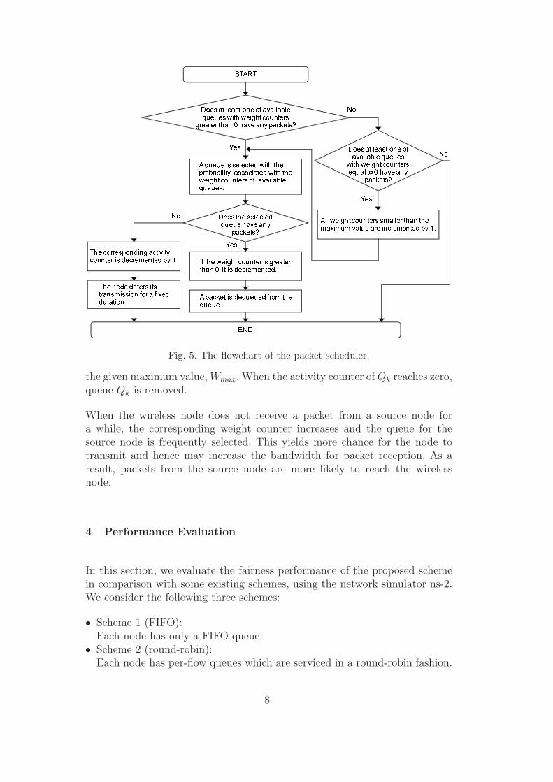
Figure 5 describes the flowchart of the packet scheduler, which selects oneof the existing queues for the next transmission according to the values ofthe weight and activity counters. First of all, the scheduler refers to all thequeues whose weight counters are greater than zero, and checks whether eachof them has packets or not. If there exists only one queue satisfying the aboveconditions, this queue is selected for the next transmission. If there exist sev-eral queues, the scheduler selects one of them in the following probabilisticmanner.
Suppose that the scheduler manages n queues and that the weight countervalue of Qk (1 ≤ k ≤ n), Wk, is wk. In the proposed algorithm, queue Qk
is selected for the next transmission with probability wk/∑n
i=1 wi. If Qk isselected and has some packets, Wk is set to wk − 1 and a packet is dequeuedfrom Qk. Otherwise the corresponding activity counter is decremented by one,and the node defers its transmission for a fixed duration twait, repeating theabove procedure. If all the queues have no packet, all the corresponding weightcounters are incremented by one. Note that the weight counters cannot exceed
7
END
START
Does at least one of available queues with weight counters
greater than 0 have any packets?
A queue is selected with theprobability associated with the weight counters of availablequeues.
Does the selected queue have any
packets?
If the weight counter is greater than 0, it is decremented.
A packet is dequeued from the queue.
Does at least one of available queues
with weight counters equal to 0 have any
packets?
All weight counters smaller than the maximum value are incremented by 1.
The corresponding activity counter is decremented by 1.
No
Yes
No
No
Yes
Yes
The node defers its transmission for a fixed duration.
Fig. 5. The flowchart of the packet scheduler.
the given maximum value, Wmax. When the activity counter of Qk reaches zero,queue Qk is removed.
When the wireless node does not receive a packet from a source node fora while, the corresponding weight counter increases and the queue for thesource node is frequently selected. This yields more chance for the node totransmit and hence may increase the bandwidth for packet reception. As aresult, packets from the source node are more likely to reach the wirelessnode.
4 Performance Evaluation
In this section, we evaluate the fairness performance of the proposed schemein comparison with some existing schemes, using the network simulator ns-2.We consider the following three schemes:
• Scheme 1 (FIFO):Each node has only a FIFO queue.
• Scheme 2 (round-robin):Each node has per-flow queues which are serviced in a round-robin fashion.
8

Table 1Basic simulation parameters.
Parameter Value
Antenna type Omni direction
Radio propagation Two-ray ground
Channel data rate 11 [Mbps]
MAC protocol IEEE 802.11 DCF
RTSThreshold 300 [byte]
Max retry times 7
Transmission range 120 [m]
Sensing range 220 [m]
Node spacing 100 [m]
Packet size 1500 [byte]
Buffer size 50 [packets]
Simulation time 120 [sec]
If the selected queue has no packet, the transmission right is immediatelyassigned to the next queue.
• Scheme 3 (proposed in [4]):Each node has a downlink queue and two uplink queues. One of the uplinkqueues is an origin queue which accumulates packets originating from thenode itself. The other uplink queue is a forwarding queue in which packetsare sent from the other nodes. Packets in both origin and forwarding queuesare transmitted in a way such that during a time interval between consecu-tive transmissions of packets originating from the node, at most one packetper source node is transmitted. For more details, the readers are referred to[4].
Table 1 shows the basic parameters used in simulation experiments. The pa-rameters for the MAC layer are cited in the widely used IEEE 802.11b stan-dard. In what follows, these parameters are used unless otherwise noted.
We use the following fairness index [12] as a measure to evaluate per-flowthroughput fairness for the case where the offered loads are the same.
FairnessIndex = 1 −∑n
i=1 |xi − x̄|2(n − 1)x̄
, (1)
where n is the number of flows, xi the end-to-end throughput of Flow i (1 ≤i ≤ n), and x̄ the average end-to-end throughput achieved by all n flows. The
9

BSWN1WN2
G
Flow 1Flow 2
WN3
G
Flow 3
G
Fig. 6. Four-node chain topology.
fairness index lies in the range from 0 to 1, and the value close to 1 indicateshigh per-flow fairness. In accordance with [4], the series of packet interarrivaltimes for each flow is generated by a constant interval multiplied by a randomnumber which is uniformly distributed in (−0.5, 0.5).
4.1 Chain Topology
In this subsection, we evaluate the performance of the proposed scheme forchain topologies.
4.1.1 Impact of Offered Traffic
First, we investigate how the offered load affects per-flow fairness in a simplechain topology. In this experiment, we consider the chain topology with threenodes and a BS, as shown in Fig. 6. Here, we have Flows 1 to 3, and thenumber of transmission hops for Flow i is i. The offered load for the threeflows is G, and its range is from 100 [kbps] to 2000 [kbps].
Figure 7 shows the fairness indices for all the schemes. We observe that boththe proposed scheme and Scheme 3 always keep high per-flow fairness, whileSchemes 1 and 2 degrade their fairness when G is greater than 700 [kbps]. Thisresult implies that the proposed scheme and Scheme 3 succeed in providinghigh per-flow fairness in comparison with the conventional Schemes 1 and 2.
Next, we consider the total throughput which is defined as the sum of end-to-end throughputs over all wireless links. For example, in Fig. 6, suppose thateach flow’s end-to-end throughput is xi (i = 1, 2, 3) and that no packet lossoccurs at each wireless link. Let Tm,n (m,n ∈ {BS, WN1, WN2, WN3}) denotethe aggregate throughput between neighboring nodes m and n. In this case,the total throughput is given by
TWN3,WN2 + TWN2,WN1 + TWN1,BS = x3 + (x2 + x3) + (x1 + x2 + x3)
= x1 + 2x2 + 3x3.
Note that if the network is overloaded, the total throughput may not be the
10

0.2
0.3
0.4
0.5
0.6
0.7
0.8
0.9
1
100 300 500 700 900 1100 1300 1500 1700 1900
Fairness Index
Offered load [kbps]
Scheme 1
Scheme 2
Scheme 3
Proposed scheme
Fig. 7. Fairness index vs. offered load for each scheme.
0
500
1000
1500
2000
2500
3000
3500
4000
4500
5000
100 300 500 700 900 1100 1300 1500 1700 1900
Total throughput [kbps]
Offered load [kbps]
Scheme 1
Scheme 2
Scheme 3
Proposed scheme
Fig. 8. Total throughput vs. offered load for each scheme.
same as the sum of multiples of end-to-end throughputs.
Figure 8 represents the total throughput against the offered load for the fourschemes. In Fig. 8, the total throughput of each scheme increases linearly, andthen decreases gradually due to congestion. A remarkable point here is thatthe total throughputs of the proposed scheme and Scheme 3 are almost thesame. From Figs. 7 and 8, we can see that the proposed scheme succeeds inachieving the same performance as Scheme 3 in terms of per-flow fairness and
11

BSWN1WN2
G
Flow 1Flow 2
WN3
G’
WN4
G
WN5
G’’
Flow 3Flow 4
Flow 5
G
Fig. 9. Six-node chain topology.
0
100
200
300
400
500
600
700
800
900
1000
Flow 1 Flow 2 Flow 3 Flow 4 Flow 5
Flow number
Throughput [kbps]
Proposed scheme
Scheme 2
Scheme 3
Fig. 10. End-to-end throughput for heterogeneous offered traffic (WN1, WN2, WN4:1000 [kbps], WN3: 200 [kbps], WN5: 100 [kbps]).
the network utilization when all source nodes have the same offered load.
4.1.2 Impact of Heterogeneous Offered Traffic
In this subsection, we investigate how the proposed scheme achieves max-minfairness when the offered loads are heterogeneous. In this experiment, theproposed scheme is compared with the existing schemes for the six node chaintopology shown in Fig. 9.
Figure 10 shows the end-to-end throughput of each flow. In this figure, theoffered loads at WN3 and WN5 are set to 200 [kbps] and 100 [kbps], respec-tively, and those for the other nodes are set to 1000 [kbps]. In the proposedscheme, we set Wmax = 12 and twait = 400 [μs]. We observe from the figurethat the end-to-end throughput of a flow with a large number of hops degradesfor Scheme 2. Especially, the end-to-end throughput of Flow 4 is significantlyreduced with the scheme. This implies that the round-robin scheduling is noteffective to improve max-min fairness.
12

0
100
200
300
400
500
600
700
800
900
1000
1 3 5 7 9 11 13 15 17 19 21 23 25 27 29
Maximum value of weight counter
Throughtput [kbps]
Flow 1
Flow 2
Flow 3
Flow 4
Flow 5
Flow 1 and Flow 2
Fig. 11. End-to-end throughput vs. maximum value of weight counter (twait = 200[μs]).
In terms of Scheme 3, we observe that end-to-end throughputs of all flows arethe same and equal to the end-to-end throughput of Flow 5. Note that theoffered load at WN5 is the smallest among all the source nodes. This resultimplies that Scheme 3 achieves high per-flow fairness to maximize the fairnessindex, however, the resulting overall throughput decreases significantly. Thisis because all the source nodes except WN5 defer its transmission until itreceives a packet from Flow 5.
On the contrary, the end-to-end throughputs of Flows 3 and 5 for the pro-posed scheme are almost equal to their respective offered loads. In addition,the end-to-end throughputs of the other source nodes are almost the sameand larger than those achieved by Scheme 3. This result implies that the pro-posed scheme significantly improves max-min fairness in comparison with theexisting schemes.
4.1.3 Effect of Parameter Adjustment
In this subsection, we investigate how the parameter Wmax affects the perfor-mance of the proposed scheme. Here, the chain topology shown in Figure 9 isconsidered, and the offered loads at WN3, WN5 and the others are set to 200[kbps], 100 [kbps] and 1000 [kbps], respectively. twait is set to 200 [μs].
Figure 11 shows the end-to-end throughput against Wmax. When Wmax issmall, the end-to-end throughputs of Flow 1 and Flow 2 are the same andreach the highest value among all the end-to-end throughputs. Note that theend-to-end throughput of Flow 4 is almost the same as that of Flow 5 eventhough the offered load at WN4 is greater than that at WN5. This is because
13
0
100
200
300
400
500
600
700
800
900
1000
1 3 5 7 9 11 13 15 17 19 21 23 25 27 29
Maximum value of weight counter
Throughtput [kbps]
Flow 1
Flow 2
Flow 3
Flow 4
Flow 5
Flow 1 and Flow 2
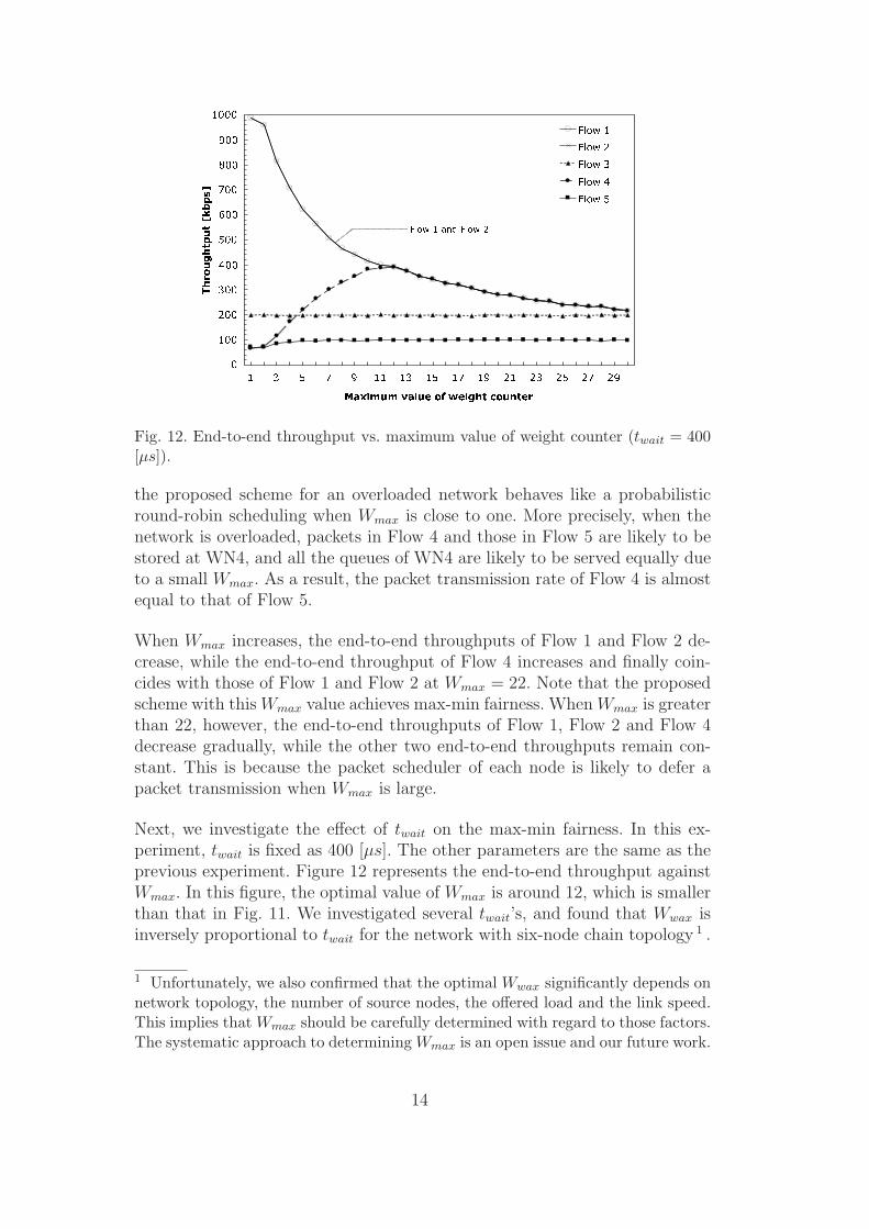
Fig. 12. End-to-end throughput vs. maximum value of weight counter (twait = 400[μs]).
the proposed scheme for an overloaded network behaves like a probabilisticround-robin scheduling when Wmax is close to one. More precisely, when thenetwork is overloaded, packets in Flow 4 and those in Flow 5 are likely to bestored at WN4, and all the queues of WN4 are likely to be served equally dueto a small Wmax. As a result, the packet transmission rate of Flow 4 is almostequal to that of Flow 5.
When Wmax increases, the end-to-end throughputs of Flow 1 and Flow 2 de-crease, while the end-to-end throughput of Flow 4 increases and finally coin-cides with those of Flow 1 and Flow 2 at Wmax = 22. Note that the proposedscheme with this Wmax value achieves max-min fairness. When Wmax is greaterthan 22, however, the end-to-end throughputs of Flow 1, Flow 2 and Flow 4decrease gradually, while the other two end-to-end throughputs remain con-stant. This is because the packet scheduler of each node is likely to defer apacket transmission when Wmax is large.
Next, we investigate the effect of twait on the max-min fairness. In this ex-periment, twait is fixed as 400 [μs]. The other parameters are the same as theprevious experiment. Figure 12 represents the end-to-end throughput againstWmax. In this figure, the optimal value of Wmax is around 12, which is smallerthan that in Fig. 11. We investigated several twait’s, and found that Wwax isinversely proportional to twait for the network with six-node chain topology 1 .
1 Unfortunately, we also confirmed that the optimal Wwax significantly depends onnetwork topology, the number of source nodes, the offered load and the link speed.This implies that Wmax should be carefully determined with regard to those factors.The systematic approach to determining Wmax is an open issue and our future work.
14

BS
WN
WN
WN
WN
WN
WN
WN
WN
WN
WNWN
WN
WN
WN
Fig. 13. Sample of generated topologies.
Table 2Average of fairness indices for the 50 different topologies.
Proposed scheme Scheme 2 Scheme 3
Sample average 0.92916 0.74649 0.76627
95% CI (0.91232, 0.94599) (0.72865, 0.76434) (0.74655, 0.78599)
4.2 Random Topology
In this subsection, we investigate the performance of the proposed schemefor random topology in case where the offered loads are homogeneous amongnodes. We consider a 500 x 300 [m2] simulation plane. In this plane, a BS islocated at one of four corners and 14 nodes are randomly placed such thateach node has no relay node within a 60-meter radius but has at least onerelay node within a 110-meter radius. The number of sample planes generatedfor this simulation experiment is 50. For each simulation plane, the fairnessindex was calculated for the proposed scheme and Schemes 2 and 3. In termsof the routing protocol, we adopted Destination-Sequenced Distance Vector(DSDV) [8].
Figure 13 shows a sample of automatically generated topology and its commu-nication pathway. Figure 14 shows the fairness indices for the three schemes.The horizontal axis represents the simulation-run number. The offered loadat each node is set to 150 [kbps]. It is observed from Figure 14 that in mostcases, the fairness index of the proposed scheme is the largest among the threeschemes. Table 2 shows the average of the fairness indices and the 95% confi-dence intervals (CI’s) for the simulation results in Figure 14. We observe thatthe proposed scheme achieves higher fairness than the existing schemes in arandom topology. From these results, we can claim that the proposed scheme
15

0.5
0.6
0.7
0.8
0.9
1
1 4 7 10 13 16 19 22 25 28 31 34 37 40 43 46 49
Simulation number
Fairness Index
Proposed scheme
Scheme 2
Scheme 3
Fig. 14. Fairness indices for the 50 different topologies.
significantly improves the fairness performance for not only chain-topologynetworks but also random-topology networks.
5 Conclusion
In this paper, we considered the issue of unfairness for the per-flow through-put in IEEE 802.11 multihop wireless LANs. We proposed a probabilisticpacket-scheduling scheme in which an autonomous traffic control mechanismis introduced without the modification of the MAC protocol. The performanceof the proposed scheme was investigated by ns-2 simulation. From the simu-lation results, it was observed that the proposed scheme can achieve higherper-flow fairness than the existing schemes in both chain and random topolo-gies. In addition, the proposed scheme can also improve max-min fairness. Wealso found that in chain-topology networks, the optimal value of the weightcounter is inversely proportional to the unit time of deferring. However, find-ing the optimal weight counter value is currently an open problem, and thisis our future work.
References
[1] K. Fall and K. Varadhan, “The Network Simulator: ns-2,”http://www.isi.edu/nsnam/ns/.
[2] P. T. Giang and K. Nakagawa, “Improvement of Fairness by PCRQ scheduling
16

in Multihop Wireless Ad hoc Networks,” in Proc. of Asia-Pacific Symposiumon Queueing Theory and Network Application, pp. 339–348, 2007.
[3] X. L. Huang and B. Bensaou, “On Max-min Fairness and Scheduling in WirelessAd-Hoc Networks: Analytical Framework and Implementation,” in Proc. ofMobiHOC 2001, 2001, pp. 221–231.
[4] H. Izumikawa, H. Ishikawa and K. Sugiyama, “Scheduling Algorithm forFairness Improvement among Subscribers in Multi-hop Wireless Networks,”Electronics and Communications in Japan (Part I: Communications), Vol. 90,no. 4, pp. 11–22, April 2007.
[5] J. Jun and M. L. Sichitiu, “Fairness and QoS in Multihop Wireless Networks,”in Proc. of IEEE 58th Vehicular Technology Conference, Vol. 5, pp. 2936–2940,2003.
[6] Z. Li, S. Nandi and A. K. Gupta, “ECS: An Enhanced Carrier SensingMechanism for Wireless ad hoc Networks,” Computer Communications, Vol. 28,pp. 1970–1984, 2005.
[7] S. Nelson and L. Kleinrock, “Spatial TDMA: A Collision-Free multihop ChannelAccess Protocol,” IEEE Transactions on Communications, Vol. 33, No. 9,pp. 934–944, 1985.
[8] C.E. Perkins and P. Bhagwat, “Highly Dynamic Destination-SequencedDistance-Vector Routing(DSDV)for Mobile Computers,” in Proc. of ACMSIGCOMM ’94, pp. 234–244, 1994.
[9] B. Radunovic and J. Y. Le Boudec, “Rate Performance Objectives of MultihopWireless Networks,” IEEE Transactions on Mobile Computing, Vol. 3, No. 4,pp. 334–349, 2004.
[10] S. Ray, J. B. Carruthers and D. Starobinski, “RTS/CTS-Induced Congestion inAd Hoc Wireless LANs,” in Proc. of IEEE WCNC 2003, Vol. 3, pp. 1516–1521,2003.
[11] N. B. Salem and J. P. Hubaux, “A Fair Scheduling for Wireless Mesh Networks,”in Proc. of First IEEE Workshop on Wireless Mesh Networks(WiMesh 2005),pp. 81–88, 2005.
[12] D. Vardalis, “On the Efficiency and Fairness of TCP over Wired/WirelessNetworks,” Master Thesis, State University of New York at Stony Brook, 2001.
[13] “Wireless LAN Medium Access Control(MAC)and Physical Layer(PHY)Specifications,” IEEE 802.11 Standards, 1999.
[14] S. Xu and T. Saadawi, “Does the IEEE 802.11 MAC Protocol Work Wellin Multihop Wireless Ad Hoc Networks?,” IEEE Communications Magazine,Vol. 39, No. 6, pp. 130–137, 2001.
17