A O D M A CAD WITH MICROSOFT - Ammattikorkeakoulut AutoCAD is a versatile and powerful modelling...
42
ASPECT ORIENTED DATA MANAGEMENT IN AUTODESK AUTOCAD WITH MICROSOFT .NET Barna Kocsis Bachelor’s Thesis December 2009 Degree Programme in Information Technology
Transcript of A O D M A CAD WITH MICROSOFT - Ammattikorkeakoulut AutoCAD is a versatile and powerful modelling...

ASPECT ORIENTED DATA MANAGEMENT IN AUTODESK AUTOCAD WITH MICROSOFT .NET
Barna Kocsis
Bachelor’s Thesis
December 2009
Degree Programme in Information Technology

2
Author
KOCSIS, Barna
Type of publication
Bachelor´s Thesis
Date
09.12.2009
Pages
42
Language
English
Confidential
Until ______________
Permission for web
publication
Title
ASPECT ORIENTED DATA MANAGEMENT IN AUTODESK AUTOCAD WITH MICROSOFT .NET
Degree Programme
Information Technology
Tutor
SALMIKANGAS, Esa
Assigned by
InMics Software Engineering Oy
Abstract
Autodesk AutoCAD is a versatile and powerful modelling application. However, if it is used for
special purposes, some vital features may be missing. House modelling is one of these special
purposes.
HirsiCAD is a third party extension created by InMics Software Engineering Oy to provide log
house architecture functionality for AutoCAD.
As the needs of the market and the technology are changing, every application must be updated
to meet the new requirements and HirsiCAD is no exception.
This thesis details the development process of a replacement for a HirsiCAD module to fulfil the
recent needs of the market.
In the first part of this thesis the new requirements of the market are investigated and the reason
behind starting a new project is described. In the following chapters the tools and development
kits used to develop the replacement module are introduced. Afterwards the module design and
implementation process is explained with particular regard to the theory of aspect oriented
methodology and its relevance in data management. Finally, the implemented module is
presented as a real-life example to demonstrate the benefits of the aspect oriented data
management in practice.
In the last chapter the author’s personal experiences regarding this thesis project are
summarized.
Keywords
Aspect Oriented Programming, Data Management, Autodesk, AutoCAD, Microsoft, .Net
Framework, C#, C++, ObjectARX, COM
Miscellaneous

3
CONTENTS
1 INTRODUCTION ....................................................................................................................... 5
2 THE OBJECTIVE OF THIS THESIS.............................................................................................. 5
2.1 Motivations to start a new project ..................................................................... 5
2.2 Goal of the project .................................................................................................... 6
2.3 Project specification ................................................................................................. 6
3 DEVELOPMENT ENVIRONMENT ............................................................................................. 7
3.1 Programs and SDKs from Autodesk .................................................................. 8
3.2 Programs and SDKs from Microsoft .................................................................. 9
3.3 Development configuration ............................................................................... 11
4 ANALYSIS OF THE MODULE TO BE REPLACED ................................................................... 11
4.1 Defining the building elements ........................................................................ 12
4.2 Defining the functionality ................................................................................... 13
5 DESIGN .................................................................................................................................. 14
5.1 The traditional approach ..................................................................................... 14
5.2 Aspect oriented programming ......................................................................... 16
5.3 Aspect oriented data management ................................................................ 18
5.4 Separation of the requirement aspects ........................................................ 19
6 IMPLEMENTATION ................................................................................................................ 20
6.1 Meta-programming............................................................................................... 21
6.2 Data saving and loading ..................................................................................... 21
6.3 Data display and modification .......................................................................... 25
6.4 Data reading from input ...................................................................................... 30
6.5 Summary of the public interface ..................................................................... 33
6.6 Sample implementation of the Beam ............................................................ 34
7 THE FINAL MODULE ............................................................................................................. 37
7.1 Saving and loading building elements ......................................................... 37
7.2 Modifying existing building elements ........................................................... 38
4
7.3 Creating new building elements ...................................................................... 39
8 PROJECT EVALUATION ......................................................................................................... 40
8.1 Achievements ........................................................................................................... 40
8.2 Conclusion ................................................................................................................. 41
REFERENCES .............................................................................................................................. 42
FIGURES
FIGURE 1. Screenshot of the Pillar dialog in the original HirsiCAD module ......... 11
FIGURE 2. Class diagram of the data saving and loading ............................................ 21
FIGURE 3. Class diagram of the data display and modification ................................ 26
FIGURE 4. Class diagram of data input ............................................................................... 30
FIGURE 5. Screenshot of the new HirsiCAD module displaying the building
element information stored in a line’s XData .................................................................. 38
FIGURE 6. Screenshot of the HirsiCAD module displaying building element
information exposed into the Properties Palette ............................................................ 39
FIGURE 7. Screenshot of the new HirsiCAD module prompting for user input ... 40

5
1 INTRODUCTION
Using Autodesk AutoCAD to design and model houses may at first seem to be
an easy task; however, it is very challenging.
One may create a simple sketch of a house by drawing a bunch of rectangles,
circles and lines, but that is far from enough. Certainly a model created by a
professional closely resembles a house, but there are many other things besides
the silhouette of the building that an architect must consider. For example:
What material is a wall made of? What kind of windows and doors are going to
be installed? Are the walls strong enough to carry the weight of the roof?
Since AutoCAD itself does not offer tools which enable the user to provide a
satisfying answer to the questions above, a third party application extension
software is required which can do the task.
The HirsiCAD is a house architecture extension for the Autodesk AutoCAD being
developed by InMics Software Engineering Oy. It is a tool providing support for
creating houses from wooden logs.
The present thesis discusses the aspect oriented development project of a data
management software module for HirsiCAD. At first the requirements of the
projects are introduced. Later a detailed description is presented about each
stage of the development. Finally the result of the over all process is evaluated.
2 THE OBJECTIVE OF THIS THESIS
In this chapter a closer look is taken at motivations of the development project
and what are the expected goals of it.
2.1 MOTIVATIONS TO START A NEW PROJECT
Everyone must agree with the fact that the environment is constantly evolving.
From the viewpoint of software the changes of the market and the technology
are important. For HirsiCAD to be successful it is essential to adopt these
changes as soon as possible.

6
Unfortunately the market and technology change forecasts are about as reliable
as weather forecasts. The longer the project development the less reliable the
initial forecast is. It turns out to be very difficult to predict these changes in the
long run; therefore a short reaction time project is needed.
Effects of the market
HirsiCAD is used by Kontiotuote Oy to create the plans for their log houses.
Since the housing market is always progressing (the fashion is changing, new
laws are made, new building materials are discovered, etc.), there is a natural
need to update the programs they are using at Kontiotuote Oy.
Effects of the technology
AutoCAD is a continuously developed application by Autodesk. Nearly in every
version of it the programming interface is changed. Most recently with the
introduction of .Net support in AutoCAD, the old programming API-s are being
deprecated from day to day.
To take up the market changes the customers of HirsiCAD are always expected
to use the latest version of AutoCAD.
2.2 GOAL OF THE PROJECT
Considering all the reasons above a decision was made at InMics Software
Engineering Oy to start a new short term development project updating
HirsiCAD.
The goal of this project is to evolve, redesign and reimplement an old module of
HirsiCAD using cutting edge technology to meet the new requirements of the
customer. In fact the main reason to start a new project was the technological
advancement; therefore functional changes during this project are not likely to
be implemented.
2.3 PROJECT SPECIFICATION
Purpose
The software module developed within this project intends to provide a feature
rich log house design environment as an updated replacement of the currently
existing HirsiCAD tool.

7
Scope
The scope of the software module is local. It is a part of the HirsiCAD application
and will not be shipped alone. It is only deployed with HirsiCAD and can be
accessed only if directly installed onto an existing AutoCAD installation.
Functional requirements
Functional requirements are the features of an application fulfilling the needs of
its user. In most development processes these requirements are established by
directly involving the user into the system specification phase of the software
development.
Since the main reason for this update is the technological advancement, the
requirement specification does not necessarily require interaction with the
customers. This is the reason why functional requirements are to be established
later in the design phase based on the analysis of the module to be replaced.
There is no new functionality that should be implemented; only the existing
functionality must be completely preserved.
Non-functional requirements
Non-functional requirements define the contractual, quality of service
requirements of an application. In a well designed application the existence of
the modules fulfilling the non-functional needs are hidden from the eyes of the
user.
The new module must provide a more reusable implementation, using cutting
edge technology, while maintaining the backwards compatibility with older
HirsiCAD versions.
3 DEVELOPMENT ENVIRONMENT
In this chapter the development environment for this project is selected.
The development environment is a collection of applications and tools used to
create new software. The success of a project depends on how carefully the
development environment was chosen.

8
3.1 PROGRAMS AND SDKS FROM AUTODESK
In this section the programs and development kits produced by Autodesk are
introduced.
AutoCAD
Autodesk AutoCAD is a versatile computer aided design (CAD) application for
two and three dimensional drafting. In AutoCAD the draft is called drawing and
contains entities. Entities such as lines, circles, and text are the primitive (mostly
2D) visible objects serving as the basis for more complex objects. The most
recent releases of AutoCAD are also including full support for 3D entities and
solid object modeling.
The early versions of AutoCAD were supported on UNIX based operating
systems unfortunately at the moment it runs exclusively on Microsoft Windows.
Autodesk AutoCAD is nowadays one of the most wide-spread general purpose
CAD applications. There are as many ways to use the program as there are a
number of different users. Therefore AutoCAD customization has become a
superior need of the market. Even since the early versions, to fill the holes of the
market, Autodesk made it possible for third party developers to extend
AutoCAD's features and capabilities. A wide number of programming interfaces
are provided to let everyone select what they prefer to use. The most notable
interfaces are AutoLISP, VBA and ObjectARX.
AutoLISP
The first programming interface exposed by AutoCAD based on the Lisp
programming language.
VBA
The acronym VBA stands for Visual Basic for Applications. As the name says this
is a Visual Basic 6 based programming environment designed to provide rich
development capabilities. The main difference between VBA and Visual Basic 6
is that VBA runs in the same process space as AutoCAD.
Recently VBA is becoming deprecated. This does not mean that Autodesk will
ban it from AutoCAD, but its improvement has been slowed down.
ObjectARX
ObjectARX was introduced in 1997. It is the abbreviation of AutoCAD Runtime
Extension. This is a software development kit (SDK) for extending AutoCAD.
ObjectARX made the developers available to define new commands, access the

9
drawing database, customize the user interface and use the graphical system.
For more information please see http://www.autodesk.com/objectarx.
The ObjectARX SDK is primarily a collection of headers and static libraries meant
to be used for AutoCAD extension development. The officially supported
programming language is C++, but an ObjectARX module can be written in any
programming language that supports building a dynamic link library (commonly
referred as .dll). In order to make a difference between ObjectARX modules and
other general purpose binary libraries the use of the .arx file extension is
preferred over the more common .dll.
(see http://images.autodesk.com/adsk/files/objectarx_2010_training.zip)
A compiled .arx file can be directly loaded into the AutoCAD environment and
allows the user to access the new features provided by the module. Since an
ObjectARX module is a native binary dll, there is no performance penalty and
the execution speed of the extension will be the same as the speed of native
features.
Using ObjectARX is hard. Extensive C++ and native Windows programming
knowledge (including COM and Microsoft Foundation Classes) is required to
develop a custom module.
Usually each AutoCAD version arrives with an updated ObjectARX SDK. Using
extensions built with older versions of the SDK should not cause problem,
although when AutoCAD tries to load these older extensions sometimes a
warning message is displayed because of the SDK version mismatch. Recently
entering to the x64 era caused another issue of binary incompatibility between
32 and the 64 bit AutoCAD releases, which only can be solved with shipping two
versions of the custom ObjectARX extension for both platforms.
To overcome these compatibility problems Autodesk included the support of
the Microsoft .Net platform into the AutoCAD by providing a wrapper for native
ObjectARX types, procedures and functions.
3.2 PROGRAMS AND SDKS FROM MICROSOFT
In this section the programs and development kits produced by Microsoft are
introduced.

10
.Net framework
The Microsoft .Net framework is a managed software framework intended to be
the next generation application development for computers running any version
of the Microsoft Windows operating system. The .Net framework has two main
components: the common language runtime and the class library.
(see http://msdn.microsoft.com/zw4w595w.aspx)
The common language runtime (CLR) is in fact a virtual machine that manages
execution of programs. It provides core services such as memory allocation,
garbage collection and thread management. The CLR is designed to be an
abstract, hardware independent platform so that developers do not have to
consider the capabilities of the specific computer that will execute the program.
A program which is executed by the runtime is called managed application,
while a program that does not require the CLR installed is called unmanaged
application.
The class library is an extensive, object oriented collection of solutions to
everyday programming problems such as creating a user interface, managing
database connectivity, providing cryptography, and handling network
communications.
The .Net framework can be hosted by unmanaged components that load the
common language runtime into their processes and initiate the execution of
managed code, thereby creating a software environment that can exploit both
managed and unmanaged features.
Autodesk has chosen the .Net framework to provide the next level of application
development for AutoCAD.
(see http://images.autodesk.com/adsk/files/autocad_2010_dotnet_training.zip)
Unfortunately a separate .Net development environment must be obtained;
because there is not any supplied with AutoCAD.
Visual Studio
The Microsoft Visual Studio is an integrated development environment. It
includes a code editor supporting syntax highlighting, code completion (called
IntelliSense) and refactoring. There is also a compiler and an integrated
debugger which could work both as a source-level debugger and a machine-
level debugger. Visual Studio allows extensions to be added that enhance the
functionality (for example by adding support for version control systems).
Almost any .Net framework language including, but not limited to C#, VB, F# is

11
supported, while also some unmanaged programming languages are supported
(like C and C++).
3.3 DEVELOPMENT CONFIGURATION
While creating this Bachelor's Thesis, AutoCAD 2008 was used with Visual Studio
2008 running on both Microsoft Windows XP and Vista.
4 ANALYSIS OF THE MODULE TO BE REPLACED
The first step of the development is the analysis of the old module to gather all
the obligatory information needed to preserve the original functionality. Most of
the analysis is done via reading the source code, but some essential data can be
collected only by interacting with the old module from the user’s perspective
(see Figure 1).
FIGURE 1. Screenshot of the Pillar dialog in the original HirsiCAD module

12
The original module of HirsiCAD was created in VBA and designed along the
object oriented paradigm. In case of this project the functional requirements are
collected from the reverse engineered documentation of the VBA based module
to be replaced.
As the result the analysis of the old module, the following requirement is
summarized: The primary functionality of the module is the creation,
manipulation, saving and loading of the simple building elements.
4.1 DEFINING THE BUILDING ELEMENTS
The first step towards understanding the functionality of the old module is to
define what it considers to be a building element.
A building element is the extra data added by HirsiCAD to an AutoCAD drawing
entity (for example: a line, a circle, a block reference). This data holds the
answers to the building architectural questions asked in the Introduction
chapter. For example: What material is a wall made of?
In the following section each building element is described in detail.
Log
The log is a part of the wall. In the drawing a log is represented by a horizontal
line. The information, the building designers would like to store about a log is its
width, its height and its working type. The width and height are numeric values.
They define the sizes of the log in addition to the length calculated directly from
the distance between the two endpoints of the line in the drawing. The working
type defines what kind of work the construction workers should perform on the
log before building it into the house. It is a predefined enumeration of user
defined values like: "bevel", "half bevel" and "dovetail". The ability to change or
extend the log working enumeration with custom elements any time later while
using the software in production must be ensured.
Beam
The beam is the part of the roof or the floor. In the drawing a beam is
represented by a horizontal line. The notable properties of beam that this
software module is going to work with are its width, its height and its solidity
class. The purpose of width and height is identical to the case of log. The solidity
class defines the solidity of the beam which is important to know how much
weight a beam can carry. This is a predefined enumeration of values which vary
based on the wooden log used for the beam.

13
Pillar
A pillar is similar to a column, and carries the weight of the upper floors and the
roof. In the drawing the pillar is represented by a vertical line. The significant
information, the users would like to store about a pillar is its shape, width,
solidity and the carrying. The shape is a user defined enumeration of possible
lookalikes of the pillar, for example it can be "round", or "rectangular". The
width defines the size and must be stored separately along the X and Y axis. The
solidity has the same functionality it had in the case of beam: defines how much
weight a pillar can at most hold. The carrying is a logical value which is true if
the pillar carries the weight of building elements above it, false if it is used as an
interior design element and does not have any structural purpose.
Chimney
A chimney is for venting gases from the house to the outside. The chimney is
represented by a circle in the drawing. The extra property of a chimney is its
height. In some special cases an ending-cap can be placed to the above the roof
end of the chimney, which must be stored as well.
Common properties
Every building element must have a name in addition to the unique properties
defined above. The name is an identifier defined by the user for better
understanding. More than one building element may have the same name.
It is also vital to note that every object must be drawn in 3 dimensions. Points
and vectors are identified by 3 coordinates: X, Y, Z, where Z axis is the “up”
direction.
4.2 DEFINING THE FUNCTIONALITY
Since every building element supported by the old module is defined, the next
step is to categorize what kind of operations the user is able to carry out.
Creating new building elements
The module must provide AutoCAD commands for filling the extra data to
drawing entities in order to create a new building element.
In common with most other AutoCAD commands, the building element creation
commands must be able to be invoked by other HirsiCAD modules or to be
started directly by the user with entering names or short-cuts to the command
line.

14
Modifying existing building elements
The new module must provide a graphical user interface where the extra
building element data attached to each drawing entity is displayed and can be
modified.
Seamless integration into the existing HirsiCAD interface is required. Whenever
it is possible and makes sense, the software module should append its custom
controls to the existing AutoCAD user interface. For example: displaying custom
information about objects in the Properties Palette.
Saving and loading building elements
The module must provide functionality to save and load the extra building
element data defined by the user.
The extra data of each building element is a kind of persistent data. It is
essential to store the data directly into the AutoCAD drawing (.dwg) without the
need to have another file carried around.
5 DESIGN
In this chapter a software development methodology is chosen to plan the
development process of the replacement module.
5.1 THE TRADITIONAL APPROACH
Choosing a development methodology
In order to successfully fulfil both the functional and the non-functional
requirements a suitable software development methodology has to be chosen.
At first sight the object orientated methodology definitely looks promising. The
four different building element types can be implicitly mapped to four different
object types. Unfortunately this may result in implementing the same
functionality separately for each object.
Recognizing why does the chosen methodology fail
As stated by Elrad, Filman, and Bader (in October 2001/Vol. 44, No. 10
Communications of the ACM), the object oriented methodology has difficulty
localizing concerns involving global constraints and pandemic behaviours.

15
To understand the essence of this statement the data saving is discussed as a
simple example to reflect why the pure object oriented methodology is
unsuccessful under the given circumstances.
The important data from the saving point of view is stored in private fields of
the objects during runtime. When the control flow arrives to the point where the
saving has to be done, the program must write all of these private fields into
some destination stream. However, as a result of the data hiding characteristics
of the object oriented paradigm the saving method does not know what kind of
fields the object has and how they should be stored in the stream.
A common solution in many frameworks and programming languages is to
demand a special interface to be implemented by the object which needs to be
saved. Usually this interface contains the specification of one method which
takes a stream as an input and writes every field of the object into it. Although
the introduction of the saving interface makes the whole process very flexible
there are also many new problems introduced by it. The saving interface
implementation is not trivially reusable and needs having the same code in
many different classes. For example there is the Log, and there is also the
Chimney class having a field called Height. Since the Height field has the same
type in case of both objects, the saving is done the same way, but the
implementation is not reusable between the two classes because they do not
have any reference to each other.
Creating a generalized base class is possible, but error prone. In this case the
doubled field is moved up in the class hierarchy to a place, which is inherited by
both the Log and the Chimney. With this concept the problems are the
following: First of all, to extend or to modify any class in the inheritance
hierarchy is hard or even impossible. The reader is invited to imagine an
application being developed by using an agile development methodology.
There is a change in the software requirements and some class in the next
release does not need that generalized field any more, but it cannot be
removed since other classes are still in need of it. The second difficulty is to
prevent any inherited field from being saved because of the inheritance.
Another problem is that it is hard to choose a descriptive variable name for the
field which would make perfect sense in the context of each inherited class.
Actually this does not affect the functionality much, but could cause hard days
for other developers who would like understand or use the code.

16
It has now become obvious why under the given circumstances the object
oriented approach itself fails. The easiest way to overcome the problem is to
complement the object oriented paradigm with aspect orientation.
5.2 ASPECT ORIENTED PROGRAMMING
The more requirements demanded by the user, the more complex applications
are created. Newer and newer programming methodologies are developed to
reduce the design and implementation complexity of software to a level which is
completely transparent and understandable for the human mind.
Aspect orientation is one of these methodologies. To understand the reasons of
its existence a brief look is taken at the history of the programming
methodologies.
Brief history of programming methodologies
Functional decomposition
Functional decomposition was the first methodology introduced by the
FORTRAN programming language to ease the life of developers. It means
implementing every logically separated part of the whole application in its
unique procedure or function. The complexity was reduced, because these
procedures and functions were reusable nearly anywhere in the entire
application. Although reusability made the source code simpler to maintain it
had its drawbacks.
The biggest problem of functional decomposition was controlling the whole
application through setting a dozen of global or local variables visible to every
procedure and function. Matters got even messier when some procedure or
function as a side effect modified these variables. The other problem was
controlling the visibility and access level. Each procedure or function had a
specific context where it was allowed to execute. If the developer did not read
the documentation carefully there was a chance to call a procedure in an invalid
context which could corrupt or crash the entire application.
Object oriented programming
The object oriented methodology is a natural evolvement of functional
decomposition to avoid its problems by packing coherent procedures, methods
and variables into an object. This concept allowed developers to model software
parts more closely related to real entities, which dramatically increased the
readability and the maintainability of the code.

17
Objects provide modularity and code reusability at a higher level than the
functional decomposition. The main pillar of object oriented design is
encapsulation. Every data field, and every method working with these data fields
is completely inside the object and cannot be accessed directly from outside.
There should not be any outside procedure or function which could change the
fields of an object; instead there is a well defined public interface which enables
another part of the program to send a notification to the object asking to
change its state. Through this interface only the functionality is exposed to other
objects, the implementation is always kept private.
If the rules mentioned above are strictly applied then object oriented designing
greatly adds to the understandability, extendibility and maintainability of the
system. Every object knows its task, and can perform it without internal, data
corrupting changes from other objects. In a simplified interpretation a system is
nothing but a group of objects exchanging state change request messages with
each other.
In modern, object oriented programming languages, like Java or C#; an object is
represented by a class on the source code level.
A concern is a particular set of functionalities and requirements necessary in a
system. In most cases these necessary functionalities can be separated from
each other into logical sections and allow the program to be modularized.
Edsger W. Dijkstra coined the term separation of concerns in his work Selected
Writings on Computing: A Personal Perspective to describe the idea behind this
modularization to reduce the complexity of the system being developed.
According to the object oriented design rules, the purpose of a class is to fully
encapsulate all source code needed to fulfil the requirements of a specific
concern. Unfortunately this is not always possible. A cross-cutting concern is a
concern which has its implementation in more than one class. Cross-cutting
concerns cannot be independently decomposed into an object from the rest of
the system. Mixing cross-cutting concerns usually results in either scattering or
tangling of the program, or both.
The aspect oriented way
A very likely solution to overcome the code scattering and code tangling
problem is the aspect oriented methodology created by Gregor Kiczales and his
colleagues at Xerox PARC. The technology was made available to the public in
2001. (see http://people.cs.ubc.ca/~gregor/)

18
An aspect is a part of a program that provides design and implementation level
abstraction to cross-cutting concerns, therefore prohibiting violation of
separation of concerns. In other words an aspect is a feature linked to many
parts of a program, but it is not the primary goal of the program.
The aspect oriented paradigm aims to provide functionality to separate aspects
while also supporting other methodologies like function decomposition or
object orientation. The aspect oriented paradigm can be used on the top of
multiple other paradigms, therefore is not yet completely integrated into any
programming language.
The aspect oriented functionality is reached by a compilation step, which is
called weaving. The weaving takes place right before the object code is
generated. The weaver takes the aspect oriented meta-code and produces a
syntactically valid source code which can be directly compiled by an ordinary
compiler into object code.
At the time when this Bachelor's Thesis was written the most commonly used
aspect oriented framework (for example: PostSharp and AspectJ) were using
meta-language elements (macros, attributes, and annotations) to provide the
information about each aspect for the weaver.
5.3 ASPECT ORIENTED DATA MANAGEMENT
The aspect oriented paradigm – at least the way it was described in the previous
chapter - may not seem to be suitable for data management. As it was pointed
out during the weaving phase the functionality of each aspect is attached to the
rest of the program at given join points. A join point is defined to be an
instruction or any part of the program code that is reached by the control flow;
therefore it has nothing to do directly with the data processed by the program.
This causes inconsistency, because every object needs some kind of data to
operate with, but no one makes an object just for the sole purpose of having
unused data inside it, therefore placing any operation in a class which transfers
data between objects violates the separation of concerns. On the other hand if
every data management concern is separated as the main principle of aspect
orientation demands it; the functionality of every class is reduced to play the
role of the data transition object. Unfortunately this is not solution either, that is
why a place in a program must be defined where the data and the functionality
meet.

19
In C# the most common way to modify the data field of a class is to use C#
properties. The C# properties are nothing but a natural extension of the data
fields. Usually a data field is declared to be private and the class provides getters
and setters to access it. This is a good programming practice, since the data
fields are not directly accessible by other classes. Getter and setter definitions of
C# properties allows the application to perform pre and post processing of the
information that is stored in the corresponding data field. This is ideal, because
the data and the processing functionality are bounded together.
Summarizing everything it can be stated that a C# property is the join point of
data management where the main program and the aspect unite.
5.4 SEPARATION OF THE REQUIREMENT ASPECTS
By taking a look at the requirements from the aspect oriented perspective; it is
obvious that each functional requirement represents a separate cross-cutting
concern of the data management.
The aspect of data saving and loading
It is a requested feature of the application to save every persistent building
element data directly into the drawing.
A class may contain data field that holds only run-time information therefore it
is not needed to be saved or loaded. It is vital to let the developers define which
data field needs to be saved and loaded and which does not. Every data field
that must be stored belongs to the aspect of saving and loading.
It is also a design decision to specify where the data is stored. A building
element class is closely bound to some drawing entity. This is the reason why
the best solution is to store the building element data in each drawing entity's
XData.
The XData (abbreviation of eXtended Data) is a property of the DBObject class
provided to store limited amount of user specific data into any AutoCAD object.
The maximum XData size is limited at 16 Kbytes per object, since it was
introduced many AutoCAD versions before the support of the .Net framework.
The aspect of the data display and modification
An AutoCAD entity, created by HirsiCAD, stores the information which building
element it represents in the XData. It is a natural need of the user to view and
modify this data. Unfortunately there is no built-in way of AutoCAD to directly

20
display or alter an entity's XData; therefore a custom implementation must be
made.
Extending AutoCAD's Properties Palette is a very convenient solution to
seamlessly display the extra information stored to the entity XData about the
building elements.
A class marshalling the XData may contain a data field that is private; therefore
the user must not be able to view or modify it. It is vital to let the developers
define which data field can be changed by the user and which not. Every data
field that is exposed to the Properties Palette belongs to the aspect of display
and modification.
The aspect of data creation
The user must have the ability to create new building elements. In AutoCAD
using commands is the common way to create any kind of new drawing entities.
It is simple punch in a command, then following the visual guidance helping to
specify the details of the entity.
Since an entity in the program code level is represented by a class, the data
creation aspect can be interpreted as creating a new class and saving it to
XData.
A class may contain data fields that are intended for internal use; therefore they
must not be filled. It is vital to let the developers define which data field can be
filled by the user and which does not. Every data field allowed to be filled by the
user belongs to the aspect of data creation.
6 IMPLEMENTATION
In this chapter the implementation of the replacement module is discussed.
The goal of the implementation is to provide a general meta-programming
facility which can be used together with every building element class to decide
which C# property belongs to which functional requirement aspect.

21
6.1 META-PROGRAMMING
The aspect - property relationship is a kind of metadata. The metadata is
declarative information embedded into a program. Once associated with a
program entity, the metadata can be queried at runtime. This makes it possible
to take advantage of the design time information provided by an aspect during
the execution.
In the .Net framework attributes can be used for meta-programming purpose.
The metadata contained by an attribute can be queried at runtime using
reflection.
6.2 DATA SAVING AND LOADING
During the design phase the class diagram illustrated in Figure 2 was created.
This diagram shows the theoretical basis of the implementation of saving and
loading.
FIGURE 2. Class diagram of the data saving and loading

22
A look at AutoCAD’s ResultBuffer class
The XData property of a DBObject is nothing but a reference to a ResultBuffer in
which the custom data should be placed. The result buffer structure contains
data of basic value types.
Every data saved to the result buffer must be identified by a type code. In .Net
framework the TypedValue structure is provided as the unit of the data which
can be added to or read out from a ResultBuffer in one step. The TypedValue
structure has two fields. The first field is the type code, which identifies type of
the second field which contains the actual value. Although in .Net, the type of a
value can be resolved via reflection, the ObjectARX relies on the given type code
when processing the value. This concept of data typing is unusual to .Net and
descends from the legacy of C++ compilers.
Run-Time Type Information (RTTI) means knowing an object's type at runtime.
According to Bjarne Stroustrup: A History of C++: 1979− 1991, the original C++
language design did not include the run-time type information. This is the
reason why every legacy C++ compiler has simply omitted it, or specified a
unique way how it should be handled.
Even though nowadays most compilers follow the most recent ISO/IEC
14882:2003 C++ standard, which demands support of the run-time type
information, RTTI still can be disabled with command line arguments for the
sake of backward compatibility or performance. As a result of this most C++
frameworks still trust their own run-time type information.
A good example of custom RTTI is the TypedValue structure's type code field in
the case of ResultBuffer.
The value types supported by ResultBuffer:
Integer: 16 or 32 bit fixed point number.
Real: double precision floating point number.
String: in older versions the string is a binary ASCII character sequence.
The complete switch to Unicode for string representation came with
AutoCAD 2007.
Point3d: a point in the 3 dimensional space. The more frequently used
vector3d data type cannot be saved into XData therefore conversion is
always needed wherever in any software the vector3d is used.
Boolean: logical value cannot be saved to ResultBuffer directly. Usually
the 16 bit integer is used with value of 0 representing false; any other
value representing true.

23
Purpose of the ResultBufferHelper class
Specifying the type code when some data has to be added to a ResultBuffer is
tedious and encourages bad developer behaviour; therefore a public utility class
has to be provided realizing this functionality.
The ResultBufferHelper is a static class which determines the type code of every
given object then creates a new TypedValue and fills it from or writes it to a
ResultBuffer. This is intended to be a generic and type safe solution to the
possible errors caused by handmade typing of the data written into a
ResultBuffer.
Eventually the ResultBufferHelper is just a code-stub to the programmer. It does
not have any TypedValue creation pre-implemented, but provides a general
pattern.
For every type a method which converts it into a TypedValue structure and vice
versa must be implemented in another class (possibly where it is needed), and
registered via a delegate to the ResultBufferHelper.
From now on whenever some data has to be put into or get from a ResultBuffer
the ResultBufferHelper.Write or the ResultBufferHelper.Read method has to be
called. It finds the registered delegate which is able to convert the given type
and executes it.
This is much safer than the copy-pasting the same source code over and over.
Defining the metadata of the saving and loading aspect
The XDataElementAttribute class is an attribute used to mark the C# properties
which belong to the aspect of saving and loading.
During execution when the control flow arrives to a part of the program where
the actual data transition between the class members and the ResultBuffer has
to be done, a method, using reflection, retrieves the value of every property and
processes it. This is convenient because the saving and loading code becomes
universal between classes, and instead of reimplementing it separately for the
Log, the Beam, the Pillar and the Chimney, just each property has to be marked
with an attribute, and exactly one line of code does the trick.
ObjectBase – root class of the building element hierarchy
In order to make the implementation of the XDataElementAttribute reusable
between building element classes, a general ObjectBase class must be
introduced.

24
The ObjectBase is the base of every building element class. The responsibility of
ObjectBase is to provide the runtime functionality behind the
XDataElementAttribute.
Format of the XData
In AutoCAD the data in a DBObject’s XData must have a specified format. The
first Value in the XData ResultBuffer is the DxfCode.ExtendedDataRegAppName
which identifies the application created the XData. This first field must always be
present and registered to the RegAppTable of the current document.
The type information of the building element must be saved also into XData.
The drawing entity cannot be used to identify what kind of object is in its XData,
since for example the line could represent a Log, a Beam or even a Pillar. To
overcome this problem a new attribute has to be introduced. The
XDataObjectAttribute is an attribute which is used to mark classes with
properties that are going to be saved to XData. The XDataObjectAttribute has a
parameter called TypeId which will be used to identify the type. This type
information is saved to the second position of the ResultBuffer right after the
application name.
The rest of the properties can be in any order, therefore it is wise let the
developer decide in which order of the properties are written to the XData this
is why the XDataElementAttribute must have a parameter. This parameter is the
index in the result buffer where the marked C# property is written. The indexing
starts at position 2 (because the position 0 and 1 is reserved for the typing
purposes) and increases monotone without a gap.
Implementing the saving
The ObjectBase class defines the public Save method. It takes no argument and
returns a filled ResultBuffer. The heart of the method is reflection.
There is an object which is an instance of a class type derived from ObjectBase.
The first step of saving is to identify if the current class is marked with the
XDataObjectAttribute. If there is no attribute the saving fails.
Then a ResultBuffer is prepared. To the index 0 goes "HirsiCAD" the application
name, and to index 1 goes the class type identifier from the
XDataObjectAttribute.
After the header is placed in the ResultBuffer, every property of the class
marked with XDataElementAttribute is reflected. The properties are sorted by
index, and written into the ResultBuffer right after the header.

25
Finally the complete ResultBuffer is returned to the caller.
Implementing the loading
The ObjectBase class defines the public Load method. It takes a ResultBuffer as
an argument and fills in the object from it.
The first step of loading is to check if the current class is marked with the
XDataObjectAttribute. If there is no attribute the loading fails.
Then the header from the result buffer is read out and matched against the
application name and the object type defined by XDataObjectAttribute. If the
matching succeeds every property of the current class marked with
XDataElementAttribute is reflected and filled from the ResultBuffer.
Since the loading functionality in the ObjectBase is not designed to create
instances, just to fill the members of an existing class, a standalone Loader class
has to be implemented. The goal of the Loader class is to separate the concern
of data reading and object creating from the rest of the loading functionality.
Any class inherited from ObjectBase and marked with the XDataObjectAttribute
can register itself to Loader. When a particular XData has to be loaded the
Loader first examines the first two typed values of it. An exception is thrown if
the application name at index 0 does not match, or there is no class registered
whose type matches the value at index 1. If the basic identification went all right
then the .Net activator creates a new instance of the particular class, using the
default constructor. After the instantiation the properties of the objects are filled
using the reflection based XData reading method inherited from ObjectBase.
6.3 DATA DISPLAY AND MODIFICATION
During the design phase the class diagram presented in Figure 3 was created.
This diagram serves as the basis of the implementation of data display and
modification.

26
FIGURE 3. Class diagram of the data display and modification
Wrapping the Properties Palette
The Properties Palette uses COM to communicate with other components of
AutoCAD; therefore expertise is required both in ObjectARX and C++ from
developers who want to utilize its features. A part of the Properties Palette
functionality has managed wrapper classes for .Net in the
Autodesk.AutoCAD.Windows.ToolPalette namespace, but it is not enough for
this component. C++ in combination with .Net is used to create the wrapper for
the unexposed but needed functionality.
C++/CLI
Applications written in C# must rely on the .NET framework PInvoke feature to
access the COM system. In some special cases even the compiler support of the
unsafe keyword must be additionally enabled, which is required for any
operation involving pointers.
The C++/CLI is a Microsoft specific extension of C++ standardized by ECMA as
ECMA-372 filling the gap between managed and unmanaged code. In contrast
to C# the C++/CLI programming language supports placing both native and
garbage collected program codes into the same .Net assembly without any
extra settings needed.

27
The native – managed wrapper layer
The wrapper to be created is based on the Property Palette interfaces defined in
the dyprops.h include of the ObjectARX SDK. Since AutoCAD uses COM, the
only thing to be created is a managed interface corresponding to each native
interface.
To avoid confusion: From now on the term "C# property" will be used to identify
a class member, while the term "dynamic property" will be used to identify the
COM object in AutoCAD's Properties Palette.
In the following paragraph the original wrapper implementation published by
Kean Walmsley is discussed and extended further (see http://through-the-
interface.typepad.com/through_the_interface/2009/03/exposing-autocads-
properties-palette-functionality-to-net---part-1.html).
The ObjectARX COM interfaces that this module wraps are follows:
IPropertyManager interface:
The IPropertyManager is used to add a custom property for a given type
of AutoCAD entity. Actually the IPropertyManager2 will be wrapped,
because its functions take IUnknown pointers instead of
IDynamicProperty pointers as parameters. This is needed since from
HirsiCAD the interaction with the property manager is done through the
COM.
IDynamicProperty interface:
The IDynamicProperty is the main interface through which the Properties
Palette determines the behaviour of dynamic properties. In fact the
IDynamicProperty2 is wrapped, for the same reason as
IPropertyManager2.
IDynamicEnumProperty interface:
The IDynamicEnumProperty is wrapped to support the drop-down list
style control display in the Properties Palette.
IDynamicPropertyNotify interface:
Every dynamic property created owns an IDynamicPropertyNotify pointer
of the Properties Palette. When a dynamic property is changed, the
Properties Palette is notified through this interface so that it knows to
refresh the values of the properties it is displaying. Actually the

28
IDynamicPropertyNotify2 is wrapped for the sake of COM interoperability
as in the case of the IPropertyManager or the IDynamicProperty.
The actual implementation of the wrapper is relatively easy. Only a managed
interface should be declared with all the properties that the native interface had.
Also the managed interface must be marked with attributes to indicate that it
interoperates with COM.
The managed layer
The need to provide a programmer friendly IDynamicProperty implementation
is high, since a direct wrapper was created, therefore every interface has its
legacy marks of C++ and COM. Using this kind of interfaces could be hard for
anyone who is familiar only with C#.
DynamicPropertyBase class:
The DynamicPropertyBase is a minimalistic implementation of the
IDynamicProperty provided in C#.
The goal of DynamicPropertyBase is to provide .Net friendly C#
properties instead of getter and setter methods while also completely
hiding the callback based notification system with standard .Net events
and delegates.
DynamicProperty class:
The DynamicProperty class is a refinement of the DynamicPropertyBase
class, while also introducing the property categorization with providing a
standard implementation of the IAcPiCategorizeProperties interface.
If a class does not implement the IAcPiCategorizeProperties interface at
all, its properties are put under the General category, although this
interface is optional; however strongly recommended to avoid confusing
the user. If everything is put under the General category (which is the
default behaviour) then a user, who is not so experienced, will not know
which dynamic property was originally supplied by AutoCAD, and which
property is an extension by HirsiCAD.
DynamicEnumProperty class:
This is a subclass of the DynamicProperty class extending its functionality
by implementing the IDynamicEnumProperty interface.

29
This class is proposed to provide the support for the predefined
enumeration type of building some building element data. This comes
handy for example to display the possible working types of a Log or the
valid shapes of a Pillar.
Interaction between dynamic properties and entities
When the value of a dynamic property has to be display a transaction is started
to retrieve the current entity from the drawing based on the object ID supplied
by the Properties Palette. When the entity is found the Loader class converts the
XData into a C# object with a single line of code. As the result of this process
the value of the corresponding C# property of the created object is shown by
the dynamic property.
Applying the Factory Pattern
There are many different classes like Log, Pillar, etc. with need for different types
of dynamic properties for each C# property defined. Coding every dynamic
property by hand would be a great effort even for the best programmers. It
takes much time and also messes up the internal structure of the class. By taking
a second approach to the problem it can be realized that this is an ideal
example to explain why the factory pattern was ever designed.
The essence of the factory pattern is to define an interface for creating an
object, but letting the subclasses decide which class to instantiate. The
realization of the Factory Pattern in the source code ensures the separation of
the modification concern while also providing dependency injection.
Defining the metadata of the display and modification aspect
Creating a separate PropertyFactory class seems to solve the entire problem. To
display the data of a building element in the Properties Palette a separate
DynamicProperty wil be instanced for each C# property marked with the
AutoCADPropertyAttribute.
In the source code level the AutoCADPropertyAttribute represents the aspect of
data display and modification. The AutoCADPropertyAttribute has parameters
to define the lookalike and the behaviour of the dynamic property. The first
parameter is the display name, which is the name of dynamic property. The
second parameter is the description which gives the user a brief, textual
explanation of the dynamic property. A read only parameter is also specified to
let the application decide whether the user can edit the dynamic property or
not.

30
In order to support the predefined list properties (for example the working type
of a Log), a parameter has to be introduced which takes a string array
containing all the possible keywords. However, the class instances cannot be
declared to attribute parameters but only types, this is why a new
IKeywordEnumeration interface has to be introduced. If any class implements
this interface and has a default constructor, it can be registered with its type to
the AutoCADPropertyAttribute.
Cooperation between the attribute and the runtime
The PropertyFactory defines the Expose method. This method expects a type as
the input parameter, where any class can be defined. The method simply reflects
every C# property of the parameter type marked with the
AutoCADPropertyAttribute, and creates the DynamicProperty or the
DynamicEnumProperty based on the informations retrieved from the attribute.
6.4 DATA READING FROM INPUT
During the design phase the class diagram shown in Figure 4 was produced.
This diagram provides the theoretical basis of the implementation of data
reading from input.
FIGURE 4. Class diagram of data input

31
A look at AutoCAD input model
The AutoCAD input model is based on user prompting. When an application
would like to get any kind of data from the user it retrieves the current AutoCAD
document. The next step is to get the current editor. The editor defines getter
methods for every primitive type used by AutoCAD. Calling the appropriate
getter method displays an edit field next to the cursor where the user is asked
to enter the input. If a valid input is given, the editor returns with a
PromptResult instance containing the input.
There is a possibility for the user to change his mind and cancel the input
process. Cancelation can be recognized by the application by validating the
return state stored in PromptResult.Status.
Introducing the InputHelper class
The InputHelper is a static utility class the purpose of which is to provide a type
safe, generalized interface to the AutoCAD input system. It must be extensible
but not depending from the currently active document.
By default the input helper has no implementation how a type can be loaded, it
is just a container for methods which could carry out the actual data reading.
A data reading method is a traditional C# class member function which takes
two arguments: the current document and the message to be displayed to the
user, and return the data entered by the user, or throw an exception if the input
was cancelled.
The InputHelper keeps track of all installed input methods in an internal
dictionary. The extension of the input handler is done via registering these
methods to a specified input type.
After registering each input reading method, the data retrieving is simple. As the
first step the caller must test if the type he wants to load is supported or not,
then just call the InputHelper.Read function which performs the reading. The
ReadInput is a generic method, and the argument it is expecting the type of the
data to be read. The current document and the message are both necessary to
be specified for the sake of wider code reusability.
Defining the metadata of the input aspect
Every building element has many properties that must be filled from user input.
Since there is a separate prompt method provided for every data type it would
be very error prone to copy-paste the same piece of code to every place where
we need some user input. It is worth the trouble to create a generalized helper

32
class, because the whole input model can be simplified to be just a few lines of
code.
A new attribute should be introduced to provide the metadata for the input
aspect. This new attribute is called SupportUserInputAttribute. Its only purpose
is to indicate which C# properties are to be filled directly from AutoCAD's
command prompt. It is important to mention that only C# properties with set
functionality are allowed to be marked with this attribute
The SupportUserInputAttribute has two parameters. The first parameter is the
message string which is displayed to the user. The other parameter is a type
expecting some class implementing the IKeywordEnumeration, to support the
predefined list type of properties.
Where should be the method placed which realizes the runtime functionality of
the input aspect? The responsibility of reading must not spawn more utility
classes or violate the constraints of the object oriented paradigm. The choices
are limited because the input handling method should be accessible from all of
the building element classes, and is not allowed to create a new object, just to
fill the properties of an existing one.
From every perspective a convenient choice is the ObjectBase. Since it is the
common super class of the Beam, the Log, the Pillar and the Chimeny, its
functionality is inherited and visible from everywhere.
Reading the input
The ObjectBase class defines the public FromUserInput method. The method
first queries every settable property of the current class type using reflection.
Then it iterates through every property and if a property is marked with the
SupportUserInputAttribute the InpuHelper.Read is invoked to get the user data
stored into the property's value.
During an input session every property is expected to be filled, therefore
cancelling should not result in an inconsistent object state. This can be achieved
by filling newly constructed objects only, or creating a backup before
proceeding with the input reading.

33
6.5 SUMMARY OF THE PUBLIC INTERFACE
The following section describes which classes are exported by the public
interface of the new module. These classes can be used to define each building
element.
ObjectBase is the common base class for every building element
implementation. The ObjectBase class provides all the aspect oriented data
management functionality, since it is not weaved during compilation like in
most aspect oriented environments.
Classes referenced by the aspect of data saving and loading:
ObjectBase: defines the Save and Load method which does the actual
data storing.
Loader: creates a new object and fills it from XData.
XDataObjectAttribute: helps the Loader to determine which XData object
can be stored in which class.
XDataElementAttribute: used during both the saving and the loading to
determine which C# property is saved at which XData position.
Classes referenced by the aspect of data display and modification:
AutoCADPropertyAttribute: with defining this attribute, one can decide
how each C# property is displayed as a dynamic property.
PropertyFactory: creates and registers a dynamic property for every C#
property. Also takes care of the disposal of the dynamic properties when
AutoCAD is closing down.
IKeywordEnumeration: defines a predefined list of values from which the
user can select.
Classes referenced by the aspect of data creation:
ObjectBase: defines the FromUserInput method which does the actual
input reading.
SupportUserInputAttribute: used to identify which C# property has to be
filled from user input.
IKeywordEnumeration: defines a predefined list of values from which the
user can select.

34
6.6 SAMPLE IMPLEMENTATION OF THE BEAM
Due to the number of code lines and the nature of this thesis the whole
implementation cannot be provided at this point.
As an example a part of the Beam class implementation is presented, which is
able to symbolize how easily each aspect can be used in the practice.
In the result module every other building element is implemented in the same
way as the Beam.
Creating the Beam class
The first step is to create the enumeration class providing the valid solidities of a
Beam here.
// Defines the valid solidties of a beam class BeamXSolidity : IKeywordEnumeration { // The available predefined options which are selectable // as a valid Beam solidity // This property is defined by the IKeywordEnumeration and implemented here public IEnumerable<KeyValuePair<string, string>> Options { get { // Get the solidity form an XML file, by extending the XML file the use // is able to define his own value return XMLFileLoader("beamsolidity.xml") } } }
The second step is to create a simple C# class with public properties derived
from ObjectBase using the attributes mentioned above.

35
// The type code of the Beam element is "BeamXType" this will be saved // to the XData and used during loading and updating. This is a // custom string defined for unique identification. [XDataObject("BeamType")] class Beam : ObjectBase // Must inherit from object base { // Gets or sets the name of this Beam. // Note that the first element is written to XData at index 2, because // index 0 and 1 is reserved by ObjecBase for identification [XDataElement(2)] [AutoCADProperty(CategoryId = "HirsiCAD - Beam", Name = "Name",
Description = "This is the name of the Beam")] [SupportUserInput(Message = "Plase give me the name of this Beam:")] public string Name { get; set; } // Gets or sets the width of this Beam. [XDataElement(3)] [AutoCADProperty(CategoryId = "HirsiCAD - Beam", Name = "Width", Description = "This is the width of the Beam")] [SupportUserInput(Message = "Plase give me the width of this Beam:")] public double Width { get; set; } // Gets or sets the height of this Beam. [XDataElement(4)] [AutoCADProperty(CategoryId = "HirsiCAD - Beam", Name = "Height", Description = "This is the height of the Beam")] [SupportUserInput(Message = "Plase give me the height of this Beam:")] public double Height { get; set; } // Gets or sets the height of this line. [XDataElement(5)] [AutoCADProperty(CategoryId = "HirsiCAD - Beam", Name = "Working", Description = "This is the solidity of the Beam", Enumeration = typeof(BeamXSolidity))] [SupportUserInput(Message = "Plase give me the solidity of this Beam:", Enumeration = typeof(BeamXSolidity))] public string Solidity { get; set; } }
A command to save and load the Beam
The following code demonstrates how easily the saving is performed:
// This is an AutoCAD command that creates a line // and saves our Beam into its XData [CommandMethod("SaveBeamToLine")] public static void SaveBeamToLine() { ... // Beginning of this command // Create a new Beam Beam beam = new Beam(); // Create a new line Line line = new Line( ... ); line.SetDatabaseDefaults(); // Save the Beam into the line's XData line.XData = beam.Save(); ... // Rest of this command }

36
The following code demonstrates how to load the line's XData into the Beam
class:
// This is an AutoCAD command that reads the XData of the line and makes a // new Beam out of it, if that is possible. [CommandMethod("LoadBeamFromLine")] public static void LoadBeamFromLine() { ... // Beginning of this command // Read the object out from the drawing DBObject obj = transaction.GetObject(promptEntityResult.ObjectId, OpenMode.ForRead); ResultBuffer xData = obj.XData; // Tell the Loader that from now on it is able to load our Beam class. Loader.Register<Beam>(); // Load Beam Beam beam = Loader.Load(xData) as Beam; if (beam == null) { // Something bad happened throw new Exception("This line does not represent a Beam!"); } ... // Rest of this command }
A command which creates a new Beam from user input
The following code is an example how a Beam can created from user input
// This is an AutoCAD command that creates a Beam from user input. [CommandMethod("NewBeam")] public static void NewBeam() { ... // Beginning of this command // Get default stuff needed Document doc = Application.DocumentManager.MdiActiveDocument; Database db = doc.Database; // Read beam from input Beam beam = new Beam(); if (!linexData.LoadFromUserInput(doc)) return; // Input was cancelled using (Transaction transaction = db.TransactionManager.StartTransaction()) { // Create a new line which represents the beam Line line = new Line( ... ); line.SetDatabaseDefaults(); line.XData = beam.Save(); // Add line to the drawing transaction.AddNewlyCreatedDBObject(line, true); transaction.Commit(); } ... // Rest of this command }

37
The extension application
The extension application is the entry point where AutoCAD starts executing the
module. This is the place where the dynamic properties to AutoCAD can be
exposed by the PropertyFactory.
// Defines and AutoCAD extension application class ExtensionApp : IExtensionApplication { // The property factory creating Beam proeprties for lines private PropertyFactory pfLine; // Executed when AutoCAD loads this module public void Initialize () { // Set the Beam recognized by the loader Loader.Register<Beam>(); // Create all the AutoCAD dynamic properties from the Beam pfLine = new PropertyFactory("AcDbLine"); pfLine.Expose<Beam>(); } // Executed when AutoCAD unloads this module public void Terminate () { pfLine.Dispose(); } }
7 THE FINAL MODULE
In this chapter the final module is presented with particular regard to
demonstrate how each functional requirement is achieved by the
implementation.
7.1 SAVING AND LOADING BUILDING ELEMENTS
The first requirement was to provide functionality for the users to save and load
building elements into the AutoCAD drawing.
During the design phase this requirement was realised with the definition of the
data saving and loading aspect detailed in chapter 5.4.
The implementation of this functionality was discussed in chapter 6.2.

38
This functionality operates invisibly to the user. The normal way to test the
correctness of the implementation is to actually save and load a drawing
subsequently verifying that the original and the loaded drawing are the same. In
order to speed up the testing, a custom XData query command is used. The
command displays every TypedValue in the ResultBuffer of a user selected
entity. An example output of the command for a Line containing a Log is shown
in Figure 5.
FIGURE 5. Screenshot of the new HirsiCAD module displaying the building
element information stored in a line’s XData
7.2 MODIFYING EXISTING BUILDING ELEMENTS
The second requirement was to provide functionality for the users to modify
existing building elements.
During the design phase this requirement was realized with the definition of the
data display and modification aspect detailed in chapter 5.4.
The implementation of this functionality was discussed in chapter 6.3.
In HirsiCAD the user can view and modify the building element data attached to
a drawing entity using AutoCAD’s Properties Palette as it is shown in Figure 6.

39
FIGURE 6. Screenshot of the HirsiCAD module displaying building element
information exposed into the Properties Palette
7.3 CREATING NEW BUILDING ELEMENTS
The third requirement was to provide functionality for the users to create new
building elements.
During the design phase this requirement was realized with the definition of the
data creation aspect detailed in chapter 5.4.
The actual implementation achieving the desired building element creation
functionality is implemented as data reading form input in chapter 6.4.
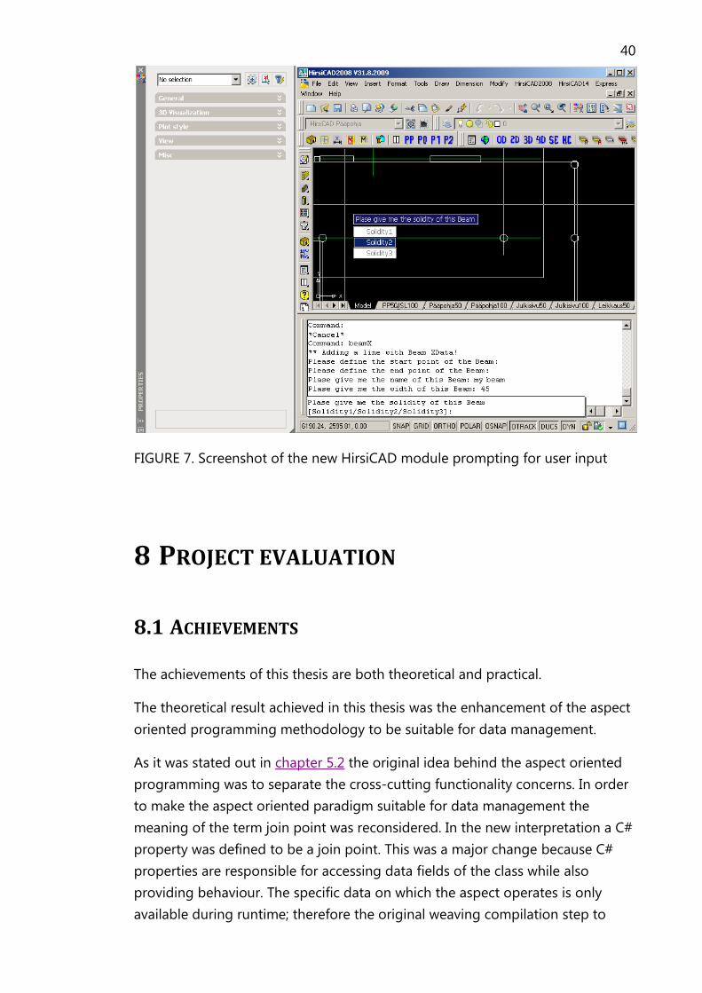
In HirsiCAD to create a new building element the appropriate command must
be punched in at the command line. As the result of the entering the command
a prompt pops up where the user is asked to input the required data. Specifying
the solidity of a Beam can be seen as an example in Figure 7.
40
FIGURE 7. Screenshot of the new HirsiCAD module prompting for user input
8 PROJECT EVALUATION
8.1 ACHIEVEMENTS
The achievements of this thesis are both theoretical and practical.
The theoretical result achieved in this thesis was the enhancement of the aspect
oriented programming methodology to be suitable for data management.
As it was stated out in chapter 5.2 the original idea behind the aspect oriented
programming was to separate the cross-cutting functionality concerns. In order
to make the aspect oriented paradigm suitable for data management the
meaning of the term join point was reconsidered. In the new interpretation a C#
property was defined to be a join point. This was a major change because C#
properties are responsible for accessing data fields of the class while also
providing behaviour. The specific data on which the aspect operates is only
available during runtime; therefore the original weaving compilation step to

41
produce the final program was not applicable. The solution of this problem was
the introduction of the special ObjectBase class. This base class realized the
aspect weaving functionality at runtime.
The practical result achieved in this thesis was to present a working
implementation of the theoretical idea proving the usefulness of the aspect
oriented data management methodology even in projects whit vast
requirements like HirsiCAD.
8.2 CONCLUSION
By the time I have finished my Bachelor's Thesis most of the component
integration tests have been finished with absolutely positive results. Although
the current release of HirsiCAD does not contain my component, I hope it will
be successfully deployed in the upcoming version.
My personal experience was positive. I really feel I was given a chance to prove
myself. During my studies I learned all the things (programming methodologies,
.Net, C++ programming, COM) in separate courses, and now I had a chance to
put everything together.
Besides using what I have known already I have also learned a lot. When I
arrived to InMics Software Engineering Oy I knew nothing about AutoCAD and
the related technology. Thankfully as a result of the help and caring of my
colleagues I really feel that I have learned the secrets of AutoCAD programming
during this project.
The communication with my colleagues was fluent and open minded. I was
actually involved in the component architecture planning process. I admire the
fact that I had the chance to argue about my opinion and I have not felt even
for a fragment of a second that I am the code-slave. I think my programming
and design skills have satisfied my employers because many of my designs
ideas are actually implemented in the final component.
The whole development process was well planned and efficiently coordinated.
The only minor annoyance that is worth mentioning was the language barrier.
The replaced component of HirsiCAD and all the other components it was
working with are completely coded and documented in Finnish language.
Unfortunately I'm not a native Finnish speaker, therefore my colleague spent a
lot of time translating everything to English for me. It happened many times,
that I had finished my task and I could not do anything but waiting for the

42
translations needed for the next task to be available. Nowadays to avoid the
recurrence of this problem the complete localization of HirsiCAD is carried out.
REFERENCES
Elrad, Filman, and Bader
October 2001/Vol. 44, No. 10 COMMUNICATIONS OF THE ACM
Dijkstra, Edsger W., Selected Witings on Computing: A Personal Perspective,
New York, NY, USA: Springer-Verlag New York, Inc., ISBN 0-387-90652-5
Stroustrup, Bjarne. A History of C++: 1979− 1991
AT&T Bell Laboratories Murray Hill, New Jersey 07974
http://www.research.att.com/~bs/hopl2.pdf
Autodesk AutoCAD .NET API Presentation
http://images.autodesk.com/adsk/files/autocad_2010_dotnet_training.zip
Autodesk AutoCAD ObjectARX 2010 Presentation
http://images.autodesk.com/adsk/files/objectarx_2010_training.zip
Autodesk Developer Center ObjectARX
http://www.autodesk.com/objectarx
Gregor Kiczales's Home Page
http://people.cs.ubc.ca/~gregor/papers.html
Kean Walmsley, Through the Interface – AutoCAD development blog
http://through-the-
interface.typepad.com/through_the_interface/2009/03/exposing-autocads-
properties-palette-functionality-to-net---part-1.html
Microsoft .Net Framework Conceptual Overview
http://msdn.microsoft.com/zw4w595w.aspx