A numerical model for bird strike on sidewall structure of an … · 2016-12-02 · A numerical...
8
A numerical model for bird strike on sidewall structure of an aircraft nose Liu Jun a , Li Yulong a, * , Gao Xiaosheng b , Yu Xiancheng a a School of Aeronautics, Northwestern Polytechnical University, Xi’an 710072, China b Department of Mechanical Engineering, The University of Akron, Akron OH 44325, USA Received 11 September 2013; revised 3 December 2013; accepted 6 January 2014 Available online 2 May 2014 KEYWORDS Bird strike; Experiment; Sidewall structure; Simulation; Smooth particles hydrodynamic (SPH) method Abstract In order to examine the potential of using the coupled smooth particles hydrodynamic (SPH) and finite element (FE) method to predict the dynamic responses of aircraft structures in bird strike events, bird-strike tests on the sidewall structure of an aircraft nose are carried out and numerically simulated. The bird is modeled with SPH and described by the Murnaghan equation of state, while the structure is modeled with finite elements. A coupled SPH–FE method is developed to simulate the bird-strike tests and a numerical model is established using a commercial software PAM-CRASH. The bird model shows no signs of instability and correctly modeled the break-up of the bird into particles. Finally the dynamic response such as strains in the skin is simulated and compared with test results, and the simulated deformation and fracture process of the sidewall structure is compared with images recorded by a high speed camera. Good agreement between the simulation results and test data indicates that the coupled SPH–FE method can provide a very powerful tool in predicting the dynamic responses of aircraft structures in events of bird strike. ª 2014 Production and hosting by Elsevier Ltd. on behalf of CSAA & BUAA. 1. Introduction Bird strikes are a significant threat to flight safety and have caused a number of accidents with human casualties. Accord- ing to the web site of the Bird Strike Committee USA, 1 over 250 people have been killed world-wide as a result of bird strikes since 1988 and the damage caused by bird and other wildlife strikes is estimated to cost USA civil aviation alone over $700 million per year. Also from the same web site, about 4800 bird strikes were reported by the US Air Force and about 10900 bird and other wildlife strikes were reported for USA civil aircraft in 2012. Collisions between birds and aircraft dur- ing flight can lead to serious damage to the aircraft structure. The point of impact is usually any forward-facing edge of the vehicle such as a wing leading edge, nose cone, jet engine cowl- ing or engine inlet. Therefore, the international certification regulations require all forward facing components to prove a certain level of bird strike resistance before they can be employed in an aircraft. 2–5 Bird-strike tests provide a direct method to examine the bird strike resistance. However, to shorten the design cycle and reduce cost, numerical simula- tions are often used to examine and assess a structure’s response to bird strike. * Corresponding author. Tel.: +86 29 88494859. E-mail addresses: [email protected] (J. Liu), [email protected]. cn (Y. Li), [email protected] (X. Gao). Peer review under responsibility of Editorial Committee of CJA. Production and hosting by Elsevier Chinese Journal of Aeronautics, (2014),27(3): 542–549 Chinese Society of Aeronautics and Astronautics & Beihang University Chinese Journal of Aeronautics [email protected] www.sciencedirect.com 1000-9361 ª 2014 Production and hosting by Elsevier Ltd. on behalf of CSAA & BUAA. http://dx.doi.org/10.1016/j.cja.2014.04.019 Open access under CC BY-NC-ND license. Open access under CC BY-NC-ND license.
Transcript of A numerical model for bird strike on sidewall structure of an … · 2016-12-02 · A numerical...

Chinese Journal of Aeronautics, (2014),27(3): 542–549
Chinese Society of Aeronautics and Astronautics& Beihang University
Chinese Journal of Aeronautics
A numerical model for bird strike on sidewall
structure of an aircraft nose
* Corresponding author. Tel.: +86 29 88494859.E-mail addresses: [email protected] (J. Liu), [email protected].
cn (Y. Li), [email protected] (X. Gao).
Peer review under responsibility of Editorial Committee of CJA.
Production and hosting by Elsevier
1000-9361 ª 2014 Production and hosting by Elsevier Ltd. on behalf of CSAA & BUAA.
http://dx.doi.org/10.1016/j.cja.2014.04.019
Open access under CC BY-NC-ND license.
Open access under CC BY-NC-ND license.
Liu Jun a, Li Yulong a,*, Gao Xiaosheng b, Yu Xiancheng a
a School of Aeronautics, Northwestern Polytechnical University, Xi’an 710072, Chinab Department of Mechanical Engineering, The University of Akron, Akron OH 44325, USA
Received 11 September 2013; revised 3 December 2013; accepted 6 January 2014Available online 2 May 2014
KEYWORDS
Bird strike;
Experiment;
Sidewall structure;
Simulation;
Smooth particles
hydrodynamic (SPH)
method
Abstract In order to examine the potential of using the coupled smooth particles hydrodynamic
(SPH) and finite element (FE) method to predict the dynamic responses of aircraft structures in bird
strike events, bird-strike tests on the sidewall structure of an aircraft nose are carried out and
numerically simulated. The bird is modeled with SPH and described by the Murnaghan equation
of state, while the structure is modeled with finite elements. A coupled SPH–FE method is developed
to simulate the bird-strike tests and a numerical model is established using a commercial software
PAM-CRASH. The bird model shows no signs of instability and correctly modeled the break-up of
the bird into particles. Finally the dynamic response such as strains in the skin is simulated and
compared with test results, and the simulated deformation and fracture process of the sidewall
structure is compared with images recorded by a high speed camera. Good agreement between
the simulation results and test data indicates that the coupled SPH–FE method can provide a very
powerful tool in predicting the dynamic responses of aircraft structures in events of bird strike.ª 2014 Production and hosting by Elsevier Ltd. on behalf of CSAA & BUAA.
1. Introduction
Bird strikes are a significant threat to flight safety and havecaused a number of accidents with human casualties. Accord-
ing to the web site of the Bird Strike Committee USA,1 over250 people have been killed world-wide as a result of birdstrikes since 1988 and the damage caused by bird and other
wildlife strikes is estimated to cost USA civil aviation aloneover $700 million per year. Also from the same web site, about4800 bird strikes were reported by the US Air Force and about
10900 bird and other wildlife strikes were reported for USAcivil aircraft in 2012. Collisions between birds and aircraft dur-ing flight can lead to serious damage to the aircraft structure.The point of impact is usually any forward-facing edge of the
vehicle such as a wing leading edge, nose cone, jet engine cowl-ing or engine inlet. Therefore, the international certificationregulations require all forward facing components to prove a
certain level of bird strike resistance before they can beemployed in an aircraft.2–5 Bird-strike tests provide a directmethod to examine the bird strike resistance. However, to
shorten the design cycle and reduce cost, numerical simula-tions are often used to examine and assess a structure’sresponse to bird strike.

A numerical model for bird strike on sidewallstructure of an aircraft nose 543
There is a long history of research efforts, especially afterthe finite element (FE) method was adopted as a tool in thelate 1970s, to develop numerical methods for bird strike simu-
lation. An extensive list of references on this subject can befound in Refs. 2–7 Hedayati and Ziaei-Rad8 introduced a birdmodel with a geometry similar to a real bird and compared
their simulation results with experimental data as well as thoseusing traditional bird models. They found that a bird couldstrike an aircraft component with its head, tail, bottom or
wings and any of these orientations might produce a differenteffect on the response of the component. Four substitute birdmodels were introduced and the best substitute model was cho-sen to capture the pressure and force exerted by the real bird
when impacting from different orientations. Smojver andIvancevic9 performed bird strike damage analysis of real aero-nautical structures using ABAQUS/Explicit and the coupled
Eulerian Lagrangian (CEL) approach. Goyal et al.10–12 per-formed a bird striking on a flat plate based on the Lagrangian,smooth particles hydrodynamic (SPH), and arbitrary
Lagrange Eulerian (ALE) approach respectively in LS-DYNA.Classical test data available in the literature and numericalmodels were used for basis of comparison. It can be concluded
that that SPH simulations best represent the fluid-like responseduring an impact. A continuum damage mechanics approachwas employed to simulate failure initiation and damage evolu-tion in unidirectional composite laminates. The CEL formula-
tion enabled the authors to overcome numerical instabilitiescaused by extreme material deformation. Wang and Yue13
developed a finite element model of bird strike on a windshield
structure including the windshield, framework, arc-frame, gas-ket and rivets, in which the adaptive contact relationship andboundary conditions were defined. A contact–impact coupling
algorithm and the explicit finite element program LS-DYNAwere employed to simulate the damage and failure process ofthe windshield structure at three bird-strike velocities. Meguid
et al.14,15 showed the mechanical property of a bird changedfrom the low velocity to the high velocity regimes. At lowspeeds it was neither uniform nor homogeneous but at pro-gressively higher speeds the bird could be considered as a
homogeneous jet of fluid impinging on a structure. Guidaet al.16 studied the bird strike against a composite tail leading
Fig. 1 Arrangement
edge, where the SPH grid free method was used to describe thebird splashing during the strike. However, none of the abovenumerical simulation approaches has been verified by real bird
strike events since there is very little published informationabout bird strike experiments on aircraft structures.
In this study, experiments of a real bird striking on the side
wall of an aircraft nose are conducted at a desired velocity of150 m/s. The explicit finite element software PAM-CRASH isused to simulate the bird strike experiments. In order to
improve the numerical stability and increase the accuracy ofthe deformation and damage prediction, a coupled SPH–FEmethod is adopted in which the bird is modeled using theSPH method with the Murnaghan equation of state and the
structure is meshed with finite elements. With the use ofSPH, numerical difficulties associated with extreme bird meshdistortion are eliminated. The material parameters are identi-
fied and the simulation results are compared with experimentaldata to verify the numerical model.
2. Test
2.1. Test apparatus
The test work described in the present paper was performed atJiangsu Anchor Co. Ltd. The objective of the test is to obtain
the dynamic response of an aircraft nose sidewall structureunder bird strike. The test data will be used by the numericalmodel presented in Section 3.
Fig. 1 illustrates the arrangement of the test equipment. Thegas gun system consists of a compressed air gun with a sup-porting compressor, instrumentation, and control system.The compressor pumps air into the air storage tank. A valve
located between the driving air storage tank and the breechof the gun is designed to drive the high pressure air from theair storage tank into the gun. After the desired air pressure
is reached in the pressure chamber, the pressure release valvewill open and the gas will expand in the barrel to push the pro-jectile forward. The bird includes the projectile and a sabot
with a required mass which must be accelerated to a desiredvelocity. Before impacting on the specimen, the bird launcher
of test equipment.

Fig. 2 Gas gun to launching bird.
Fig. 3 Target (sidewall structure of an aircraft nose).
Fig. 4 Components for the sidewall structure of an aircraft nose.
544 J. Liu et al.
cannot induce any projectile breakup or severe distortion. Inthe meantime, the projectile must be launched at the desiredorientation.
Fig. 2 shows the gas gun launching the bird. The bird usedas the projectile is a killed fowl with a mass of 1.8 kg which isheld inside a sabot packed with expanded polystyrene such
that it does not experience any position change or damage dur-ing the launching process. The sabot has to be as light as pos-sible since it constitutes an unwanted mass and must be
separated easily from the projectile just prior to the impact.The tolerance between the sabot and tube is important toensure that the bird projectile go through the barrel withoutany friction to slow it down. A sabot stopper shown in
Fig. 2 is made of a steel tube. It traps the sabot when the sabotand the projectile reach the end of the barrel. The stopper isdesigned to allow the projectile to continue its flight without
losing its velocity. In this experiment, the bird was fired at adesired velocity of 150 m/s.
Fig. 3 shows the target, the sidewall structure of an aircraft
nose. It is fixed on the edges to a clamping fixture by bolts. Theclamping fixture is mounted on a vertical steel wall by boltsand the vertical steel wall is attached to the ground. The side-
wall structure is composed of ribs, pad plate, skin-1, and skin-2as shown in Fig. 4, which are assembled by rivets.
2.2. Data acquisition
The entire bird strike process is very short, lasting only 3–4 ms.Consequently, to record the dynamic responses of the targetand capture this process, high speed data collectors must be
used. The high speed data acquisition equipment for collectingstrain, displacement and force responses usually include strainsensors and super dynamic strain gauges, displacement sensors
and amplifier, load cells, an impedance variation device, and atransient recorder. The logical connections among thesedevices are shown in Fig. 5. In this study, the test data were
collected using only strain sensors.Four strain gauges (S1–S4) are placed on the specimen to
measure the local strains and a 4-channel data acquisition sys-tem is used to collect the strain measurements at a sample fre-
quency of 10 MHz. Fig. 6(a) shows the layout of measurementlocations and Fig. 6(b) shows a photo of the specimen withstrain gauges. The velocity of the bird projectile was measured
using a laser velocity system before it strikes on the targetstructure. The entire process of bird strike on the sidewallstructure was recorded by a high speed camera.
Fig. 5 Logical connections of data acquisition equipment.

Fig. 6 Measurement of strains.
Fig. 7 Deformed and fractured sidewall structure after bird
strike.
Fig. 8 Finite element models of structure and bird.
A numerical model for bird strike on sidewallstructure of an aircraft nose 545
2.3. Test results
The desired impact velocity is 150 m/s and the actual velocityof the bird measured by the laser velocity system as it strikeson the sidewall structure is 152 m/s. These values are very
close, suggesting that the gas gun system used in this study isvery precise and stable. The direction of the flying bird is alongthe course of the aircraft. The strain gauges are placed on theinner ribs of the sidewall structure, centering about the impact
area to capture the local deformation of the specimen. Thedynamic deformation and damage process of the sidewallstructure is recorded by a high speed camera system at a time
interval of 0.5 ms for comparison with the numerical simula-tion results presented in Section 4.
Fig. 7 shows the final deformed and fractured sidewall
structure. The specimen was penetrated by the bird at theimpact area and the skin around the impact area was tornup.
3. Numerical simulation
The numerical simulation of the bird-strike test is carried out
using the explicit finite element software PAM-CRASH.Fig. 8 shows the finite element model, which consists of threeparts: the bird, the sidewall structure and the clamping fixture.The geometry of the bird is idealized as a right cylinder having
a diameter of 106 mm and a length of 212 mm to keep the stan-dard length to diameter ratio of 2:1. The idealized bird is mod-eled by the SPH method and the Murnaghan equation of state.
The sidewall structure consists of ribs, pad plate, skin-1 andskin-2 and these parts are modeled by shell elements. Theclamping fixture is modeled by solid elements. The sidewall
structure and the clamping fixture are tied together by the

Fig. 9 Dynamic compressive stress–strain curves of Al 2024 and
Al 7075.
546 J. Liu et al.
‘‘tie constraint’’. Pink elements are used to simulate the actualrivet connections.
3.1. SPH method coupled with FE
According to the photos captured by the high-speed camera,the bird becomes highly distorted and is crushed into debris
during the bird strike process. This presents a major challengefor using the finite element method to model the bird. The SPHmethod is a grid-less Lagrange technique which allows for
severe distortion and thus is adopted to simulate the bird inthis study.
SPH is a Lagrange particle method introduced by Lucy in
the 1970s17 in order to solve hydrodynamic problems in astro-physical contexts. It has been extensively applied in the studyof accretion disc, galaxy dynamics, and star collisions amongother problems. This method has been implemented in
PAM-CRASH.18 A smooth particle is input like a 3-DOF(degree-of-freedom) solid element and defined by its centerof mass, volume, part number, and domain of influence. It
can be used with great advantage to model bulk materials withno cohesion (sand, liquid, gases) or in situations where perfo-ration or mixing is expected. Note however that it can be much
more expensive to use than a classical solid element. A smoothparticle, similar to a finite element, has its own shapefunctions, reconstructed at each cycle from its dynamicconnectivity. Localization and information transmission from
one particle to another are achieved through the notion of aninterpolation distance called the smoothing length. A Particle Jis said to have a contributing neighbor Particle I, when Particle
I lies within the sphere of influence of Particle J. In such a case,Particle I is said to be connected to the central Particle J. Thesphere of influence of a particle is a multiple to its smoothing
length. The multiplication factor depends on the type of kernelused to construct the smooth particle shape functions. Detailsof the kernel functions are given in Ref.19.
Structural nodes and smooth particles must have distinctnumbers. Smooth particles can be subjected to constraints orloads as if they were nodes. In particular, finite element tosmooth particle coupling is achieved by the use of penalty con-
tacts, where the particles are slave nodes.20 The interaction ofthe particles with the finite elements may be modeled by theexisting sliding interface algorithms available within PAM-
CRASH. The most frequently used sliding interface types torelate smooth particles to finite elements are type 34 in casethe materials may be considered as sliding with dynamic con-
tact or as a tied interface when the particles are assumed tostick to the finite element surface. For a finite element mesh,the contact thickness indicates the distance away from a con-tact face where physical contact is established. For particles
interacting with finite elements, the contact thickness shouldbe representative of the particle radius, possibly augmentedwith the half-thickness of the shell structure. So the node to
surface contact is used to model the interaction between theSPH particles and Lagrange elements.
3.2. Constitutive model for bird
It has been shown that at high speed the bird can be consideredas a homogeneous jet of fluid impinging upon a structure.
Therefore it is adequate to use an equation of state to model
the bird material. The SPH method and the Murnaghan equa-tion of state implemented in PAM-CRASH provide a tool tosimulate the bird material at high velocity impact. This consti-
tutive model corresponds to a liquid with an artificiallyincreased compressibility used to perform a certain class ofhydrodynamic simulations, where the flow velocities remain
well below the physical sound speed and the compressibilityeffects are of minor importance. In such cases, the liquidmay be considered more compressible than in reality, which
may be achieved using the Murnaghan equation of statemodel. The artificial fluid must be given a speed of sound stillwell above the speed of the bulk flow and therefore it createsvery small density fluctuations. The pressure for the Murna-
ghan equation of state is given by
p ¼ p0 þ B½ðq=q0Þc � 1� ð1Þ
where q/q0 is the ratio of current mass density to the initialmass density. This constitutive model may be used to simulate
a gravity and inertia driven flow of liquids, i.e., the outflowfrom reservoirs, mixing of fluids with different densities andsloshing of liquids in partially filled containers. In such phe-
nomena the bulk flow velocities of the liquids can be ordersof magnitude smaller than their speed of sound. In the numer-ical simulations the user can regulate the sound speed and thus
greatly reduce the explicit solution time step while preserving

A numerical model for bird strike on sidewallstructure of an aircraft nose 547
the essential quality of the results. Details of the Murnaghan
equation of state can be found in Ref.21 The parameters Band c are obtained by using the optimization method describedin Ref.22 and calibrated parameter values are B = 9.3 GPa and
c = 7.14.
3.3. Material model for sidewall structure
The material model 105 in PAM-CRASH is selected as the
constitutive model for the sidewall structure. This is an elas-tic–plastic material model with isotropic damage for shell ele-ments. The plastic response is described by the strain rate
dependent Cowper-Symonds law:
r ¼ aþ bðepÞn� �
1þ ð_e=DÞ1=gh i
ð2Þ
where [a + b(ep)n] represents the static yield stress including
strain hardening, ep denotes the plastic strain, _e denotes thestrain rate, and a, b, n, D and g are material constants. Theseparameters can be obtained by fitting the test data. The mate-
rial used for the pad plate and skin is a 2024 aluminum alloywith a = 350 MPa, b = 426 MPa and n = 0.34, and the mate-rial used for the ribs is a 7075 aluminum alloy witha = 400 MPa, b = 200 MPa and n = 0.45. Fig. 9 shows the
stress–strain curves of these aluminum alloys obtained at dif-ferent strain rates, suggesting these materials can be consideredas strain rate insensitive. Therefore, the rate dependent term in
Eq. (2) is ignored. Elastic modulus and Poisson’s ratio for Al2024 are 73GPa and 0.3, for Al 7075 are 71GPa and 0.3. Afailure strain criterion is used to model the damage of the
Fig. 10 Comparison of computed and
structure. Once the equivalent tensile strain in an element
reaches the critical failure strain of the material, the elementwill be deleted. The failure strain is obtained from the tensiletest of Al 2024 and Al 7075. In the tensile test, just the failure
strain is measured and it is 0.2 for Al 2024 and 0.14 for Al7075.
4. Results and discussion
In this section, numerical simulation of a bird striking on thesidewall structure at a velocity of 152 m/s is conducted and
the simulation results are compared with the test measure-ments. Fig. 10 compares the computed and measured strainsat the four locations. Some factors such as the friction between
the bird and skin, the viscosity of the bird, the contact type andstiffness between the bird and skin etc. were difficult to define.This may result in the small difference between the simulation
and test for Fig. 10. Although there is some difference betweenthe numerical and simulation curves, the numerical resultsnot only capture the trend of the strain vs time histories atall four locations but also accurately predict the peak strain
values.The process of the bird-strike test is captured by a high-
speed camera, which lasts about 3 ms. Pictures of specimen
deformation and failure are taken at a time interval of0.5 ms and compared with the simulation results as shown inFig. 11. The SPH simulation captures the deformation
behavior of the bird, which was broken into debris and flewon the specimen. The deformation and fracture process of
measured strain vs time histories.

Fig. 11 Comparison of simulated bird strike process with pictures taken by a high-speed camera.
548 J. Liu et al.
the sidewall structure is accurately predicted by the numericalsimulation. The remarkable agreements between the simulation
results and the actual video on when the sidewall structure
fractures and the shape and size of the hole created by birdstrike suggest that the numerical model adopted in this study
is capable of predicting bird strike on the sidewall structure
A numerical model for bird strike on sidewallstructure of an aircraft nose 549
and can be used to assist designing bird strike resistant sidewallstructures.
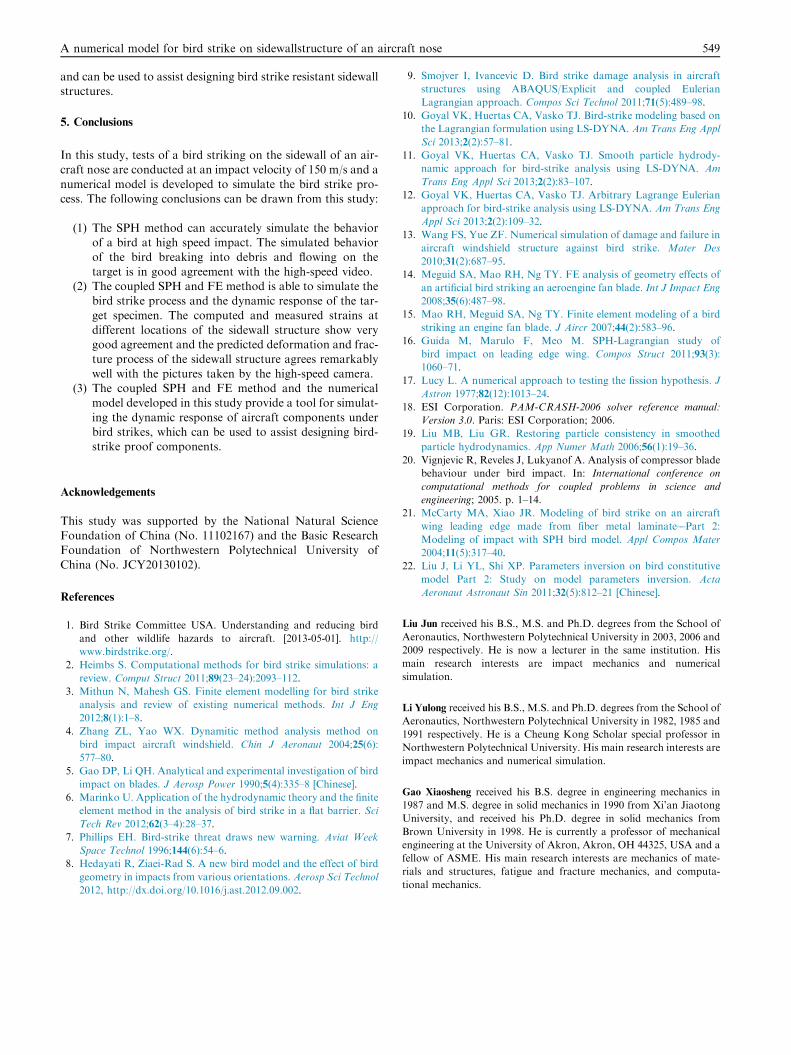
5. Conclusions
In this study, tests of a bird striking on the sidewall of an air-craft nose are conducted at an impact velocity of 150 m/s and a
numerical model is developed to simulate the bird strike pro-cess. The following conclusions can be drawn from this study:
(1) The SPH method can accurately simulate the behaviorof a bird at high speed impact. The simulated behaviorof the bird breaking into debris and flowing on the
target is in good agreement with the high-speed video.(2) The coupled SPH and FE method is able to simulate the
bird strike process and the dynamic response of the tar-
get specimen. The computed and measured strains atdifferent locations of the sidewall structure show verygood agreement and the predicted deformation and frac-ture process of the sidewall structure agrees remarkably
well with the pictures taken by the high-speed camera.(3) The coupled SPH and FE method and the numerical
model developed in this study provide a tool for simulat-
ing the dynamic response of aircraft components underbird strikes, which can be used to assist designing bird-strike proof components.
Acknowledgements
This study was supported by the National Natural ScienceFoundation of China (No. 11102167) and the Basic ResearchFoundation of Northwestern Polytechnical University of
China (No. JCY20130102).
References
1. Bird Strike Committee USA. Understanding and reducing bird
and other wildlife hazards to aircraft. [2013-05-01]. http://
www.birdstrike.org/.
2. Heimbs S. Computational methods for bird strike simulations: a
review. Comput Struct 2011;89(23–24):2093–112.
3. Mithun N, Mahesh GS. Finite element modelling for bird strike
analysis and review of existing numerical methods. Int J Eng
2012;8(1):1–8.
4. Zhang ZL, Yao WX. Dynamitic method analysis method on
bird impact aircraft windshield. Chin J Aeronaut 2004;25(6):
577–80.
5. Gao DP, Li QH. Analytical and experimental investigation of bird
impact on blades. J Aerosp Power 1990;5(4):335–8 [Chinese].
6. Marinko U. Application of the hydrodynamic theory and the finite
element method in the analysis of bird strike in a flat barrier. Sci
Tech Rev 2012;62(3–4):28–37.
7. Phillips EH. Bird-strike threat draws new warning. Aviat Week
Space Technol 1996;144(6):54–6.
8. Hedayati R, Ziaei-Rad S. A new bird model and the effect of bird
geometry in impacts from various orientations. Aerosp Sci Technol
2012, http://dx.doi.org/10.1016/j.ast.2012.09.002.
9. Smojver I, Ivancevic D. Bird strike damage analysis in aircraft
structures using ABAQUS/Explicit and coupled Eulerian
Lagrangian approach. Compos Sci Technol 2011;71(5):489–98.
10. Goyal VK, Huertas CA, Vasko TJ. Bird-strike modeling based on
the Lagrangian formulation using LS-DYNA. Am Trans Eng Appl
Sci 2013;2(2):57–81.
11. Goyal VK, Huertas CA, Vasko TJ. Smooth particle hydrody-
namic approach for bird-strike analysis using LS-DYNA. Am
Trans Eng Appl Sci 2013;2(2):83–107.
12. Goyal VK, Huertas CA, Vasko TJ. Arbitrary Lagrange Eulerian
approach for bird-strike analysis using LS-DYNA. Am Trans Eng
Appl Sci 2013;2(2):109–32.
13. Wang FS, Yue ZF. Numerical simulation of damage and failure in
aircraft windshield structure against bird strike. Mater Des
2010;31(2):687–95.
14. Meguid SA, Mao RH, Ng TY. FE analysis of geometry effects of
an artificial bird striking an aeroengine fan blade. Int J Impact Eng
2008;35(6):487–98.
15. Mao RH, Meguid SA, Ng TY. Finite element modeling of a bird
striking an engine fan blade. J Aircr 2007;44(2):583–96.
16. Guida M, Marulo F, Meo M. SPH-Lagrangian study of
bird impact on leading edge wing. Compos Struct 2011;93(3):
1060–71.
17. Lucy L. A numerical approach to testing the fission hypothesis. J
Astron 1977;82(12):1013–24.
18. ESI Corporation. PAM-CRASH-2006 solver reference manual:
Version 3.0. Paris: ESI Corporation; 2006.
19. Liu MB, Liu GR. Restoring particle consistency in smoothed
particle hydrodynamics. App Numer Math 2006;56(1):19–36.
20. Vignjevic R, Reveles J, Lukyanof A. Analysis of compressor blade
behaviour under bird impact. In: International conference on
computational methods for coupled problems in science and
engineering; 2005. p. 1–14.
21. McCarty MA, Xiao JR. Modeling of bird strike on an aircraft
wing leading edge made from fiber metal laminate––Part 2:
Modeling of impact with SPH bird model. Appl Compos Mater
2004;11(5):317–40.
22. Liu J, Li YL, Shi XP. Parameters inversion on bird constitutive
model Part 2: Study on model parameters inversion. Acta
Aeronaut Astronaut Sin 2011;32(5):812–21 [Chinese].
Liu Jun received his B.S., M.S. and Ph.D. degrees from the School of
Aeronautics, Northwestern Polytechnical University in 2003, 2006 and
2009 respectively. He is now a lecturer in the same institution. His
main research interests are impact mechanics and numerical
simulation.
Li Yulong received his B.S., M.S. and Ph.D. degrees from the School of
Aeronautics, Northwestern Polytechnical University in 1982, 1985 and
1991 respectively. He is a Cheung Kong Scholar special professor in
Northwestern Polytechnical University. His main research interests are
impact mechanics and numerical simulation.
Gao Xiaosheng received his B.S. degree in engineering mechanics in
1987 and M.S. degree in solid mechanics in 1990 from Xi’an Jiaotong
University, and received his Ph.D. degree in solid mechanics from
Brown University in 1998. He is currently a professor of mechanical
engineering at the University of Akron, Akron, OH 44325, USA and a
fellow of ASME. His main research interests are mechanics of mate-
rials and structures, fatigue and fracture mechanics, and computa-
tional mechanics.