A numerical approach to modelling the effect of a static ... · A numerical approach to modelling...
10
Proceedings of ACOUSTICS 2016 9-11 November 2016, Brisbane, Australia ACOUSTICS 2016 Page 1 of 10 A numerical approach to modelling the effect of a static pressure field on the frequency response of a clamped thin circular plate Kyle Saltmarsh 1 , Ali Karrech 2 , David Matthews 1,3 and Jie Pan 1 1 School of Mechanical & Chemical Engineering, The University of Western Australia, Perth, Australia 2 School of Civil, Environmental and Mining Engineering, The University of Western Australia, Perth, Australia 3 Underwater Sensors Group, Defence Science and Technology Group, HMAS Stirling, Australia ABSTRACT A detailed understanding of the vibrational properties of submerged objects such as submarines is essential in order to minimise sound emission and optimise sonar performance. Complications arise when hollow structures are submerged in water producing loading on one side. Not only does the water dampen the resonances of the structure but also the increase in depth produces mechanical strain within the structure that changes the resonant frequencies. In previous work, the effect of hydrostatic pressure loading on one side of a rigidly clamped plate was investigated. The modal coupling between the water tank and the vibrating plate hindered the ability to observe the experimental dependence of the plate's frequency response on the applied hydrostatic pressure. In this paper some results are presented on the effect of static pressure loading produced by air on the plate, removing the complications introduced by fluid loading and modal coupling. The aim of this work is to accurately measure these effects experimentally and identify similarities and any interesting discrepancies with the numerical models used for prediction. The finite element package ABAQUS was used to model the frequency response of the plate subjected to a static pressure field produced by a finite air cavity. 1. INTRODUCTION A detailed understanding of the vibrational properties of submerged objects such as submarines is essential in order to minimize sound emission and optimise sonar performance. The effect of hydrostatic pressure on the modal frequencies of submerged hollow structures is a complex problem. Modelling such effects using conventional finite element methods and boundary element methods is difficult. The accuracy of these models is heavily reliant on user intuition and non-systematic methods. Significant discrepancies between results and predictions were found during the frequency and mode shape analysis of a torpedo model submerged in water (Pan and Matthews, 2011). Efforts were then made to experimentally characterise the effects of hydrostatic pressure on the frequency response of a thin rigidly clamped circular plate (Saltmarsh et al, 2015). This investigation yielded interesting yet ambiguous results due to the presence of acoustic-structural coupling. The presence of tank and coupled plate-tank modes made it difficult to identify the plate mode dependence on the hydrostatic pressure. Observations drawn from the frequency response of the plate-tank rig yielded both increasing and decreasing modes, with varying dependencies. Experimental or coupled theoretical-experimental work in this area is scarce but there are many applications where such effects are very important and need to be understood. In this work, some results are presented on the effects of a static pressure field produced by an air cavity on the frequency response of the thin rigidly clamped circular plate. Some preliminary experimental results are presented and compared with the finite element model. Significant focus has been applied to the construction and verification of the finite element model, with a detailed description of the analysis methods used. 2. EXPERIMENTAL SETUP Figure 1 shows a schematic diagram of the plate test rig used for experimental analysis. A thin steel plate is clamped rigidly between two steel flanges with a much greater mass disparity to suppress the effects of structural coupling between the plate and the rig. By using such a configuration, it was possible to avoid some of the environmental complications encountered in the hydrostatic measurements mentioned above. A steel backing plate is bolted to one of the flanges to produce an enclosed acoustic air cavity on one surface of the plate. The backing plate possesses a valve to allow the adjustable pressurization of the air cavity. Thin 1 mm rubber gaskets were
Transcript of A numerical approach to modelling the effect of a static ... · A numerical approach to modelling...

ProceedingsofACOUSTICS2016 9-11November2016,Brisbane,Australia
ACOUSTICS2016 Page1of10
A numerical approach to modelling the effect of a static pressure field on the frequency response of a clamped thin circular plate
Kyle Saltmarsh1, Ali Karrech2, David Matthews1,3 and Jie Pan1
1SchoolofMechanical&ChemicalEngineering,TheUniversityofWesternAustralia,Perth,Australia2SchoolofCivil,EnvironmentalandMiningEngineering,TheUniversityofWesternAustralia,Perth,Australia
3UnderwaterSensorsGroup,DefenceScienceandTechnologyGroup,HMASStirling,Australia
ABSTRACT Adetailedunderstandingofthevibrationalpropertiesofsubmergedobjectssuchassubmarinesisessential inordertominimisesoundemissionandoptimisesonarperformance.Complicationsarisewhenhollowstructuresaresubmergedinwater producing loading on one side. Not only does thewater dampen the resonances of the structure but also theincrease in depth producesmechanical strainwithin the structure that changes the resonant frequencies. In previouswork, the effect of hydrostatic pressure loading on one side of a rigidly clamped plate was investigated. The modalcouplingbetweenthewatertankandthevibratingplatehinderedtheabilitytoobservetheexperimentaldependenceoftheplate'sfrequencyresponseontheappliedhydrostaticpressure.Inthispapersomeresultsarepresentedontheeffectofstaticpressureloadingproducedbyairontheplate,removingthecomplicationsintroducedbyfluidloadingandmodalcoupling. The aim of thiswork is to accuratelymeasure these effects experimentally and identify similarities and anyinterestingdiscrepancieswiththenumericalmodelsusedforprediction.ThefiniteelementpackageABAQUSwasusedtomodelthefrequencyresponseoftheplatesubjectedtoastaticpressurefieldproducedbyafiniteaircavity.
1. INTRODUCTION Adetailedunderstandingofthevibrationalpropertiesofsubmergedobjectssuchassubmarinesisessentialin order tominimize soundemission andoptimise sonarperformance. Theeffect of hydrostatic pressureon themodalfrequenciesofsubmergedhollowstructuresisacomplexproblem.Modellingsucheffectsusingconventionalfiniteelementmethodsandboundaryelementmethodsisdifficult.Theaccuracyofthesemodelsisheavilyrelianton user intuition and non-systematic methods. Significant discrepancies between results and predictions werefoundduringthefrequencyandmodeshapeanalysisofatorpedomodelsubmergedinwater(PanandMatthews,2011).Effortswerethenmadetoexperimentallycharacterisetheeffectsofhydrostaticpressureonthefrequencyresponseofa thin rigidly clampedcircularplate (Saltmarshetal, 2015). This investigationyielded interestingyetambiguousresultsduetothepresenceofacoustic-structuralcoupling.Thepresenceoftankandcoupledplate-tankmodesmade itdifficult to identify theplatemodedependenceon thehydrostaticpressure.Observationsdrawnfrom the frequency response of the plate-tank rig yielded both increasing and decreasing modes, with varyingdependencies. Experimental or coupled theoretical-experimental work in this area is scarce but there aremanyapplicationswheresucheffectsareveryimportantandneedtobeunderstood.
Inthiswork,someresultsarepresentedontheeffectsofastaticpressurefieldproducedbyanaircavityonthe frequency response of the thin rigidly clamped circular plate. Some preliminary experimental results arepresentedandcomparedwiththefiniteelementmodel.Significantfocushasbeenappliedtotheconstructionandverificationofthefiniteelementmodel,withadetaileddescriptionoftheanalysismethodsused.
2. EXPERIMENTAL SETUP Figure1showsaschematicdiagramoftheplatetestrigusedforexperimentalanalysis.Athinsteelplateisclampedrigidlybetweentwosteelflangeswithamuchgreatermassdisparitytosuppresstheeffectsofstructuralcoupling between the plate and the rig. By using such a configuration, it was possible to avoid some of theenvironmentalcomplicationsencounteredinthehydrostaticmeasurementsmentionedabove.Asteelbackingplateisboltedtooneoftheflangestoproduceanenclosedacousticaircavityononesurfaceoftheplate.Thebackingplate possesses a valve to allow the adjustable pressurization of the air cavity. Thin 1mm rubber gasketswere

9-11November2016,Brisbane,Australia ProceedingsofACOUSTICS2016
Page2of10 ACOUSTICS2016
placedbetweentheplate,flangeandbackingplatetoensurethatthepressurizedaircavityiseffectivelysealed.Apositive pressure pump was used to increase the static gauge pressure from 0 Pascal to 10 Kilopascal in 0.5Kilopascalincrements.Animpacthammerwasusedtoexcitetheplate.Thismethodofexcitationwasselectedoveramechanicalshakertoeliminatetheeffectsofmassloading.Asingleaccelerometer(PCB352C67)ofmass5gwasusedtomeasuretheaccelerationoftheplateduetothemechanicalexcitation.Boththestrikeandaccelerometerlocationswereselectedasirrationalratiosoftheplate’sradiustoensurenospecificmodeswerebeingsuppressedorexplicitlyexcited.Figure1showstheexperimentalsetupforthetestrig.
Figure1:Schematicoftestrigdetailingcomponents
ThesoftwarepackagePULSE(Brüel&Kjær,2015)wasusedtomeasuretheaccelerometeroutputandimpactforce. The frequency response functions of the plate were then generated through computing the ratio of theaccelerationtoimpactforce.Thisquantityisdefinedasthetransferaccelerance.Thissystemwaslimitedtoa1Hzresolution.
3. FINITE ELEMENT MODEL The finiteelementmodelwasconstructedusing thesoftwarepackageABAQUS (DassaultSystèmes,2014).
Themodelincludestheplate,rubbergaskets,flanges,bolts,backingplateandtheaircavityasdepictedinfigure1.
3.1 Geometric And Material Properties Thegeometricandmaterialpropertiesfortheentiretyofthetestrigaredetailedintable1.Thesewerethe
valuesthatwereusedinthefiniteelementmodelfortheoreticalcomparisontoexperimentalresults.Thedensity,Young’smodulus,Bulkmodulus,Poisson’s ratio,outsidediameter, innerdiameterand thicknessaregivenby thesymbolsρ,E,K,v,OD,IDandt,respectively.

ProceedingsofACOUSTICS2016 9-11November2016,Brisbane,Australia
ACOUSTICS2016 Page3of10
Table1:Experimentaltestrigproperties
3.2 Element Type Due to the disparity between the plate’s thickness and planar dimensions, the shell planar elements S4Rwereused formodelling.Theelement typeS4R isa reduced integrated,general-purpose, finite-membrane-strainshellelement.Theelement'smembraneresponseistreatedwithanassumedstrainformulationthatgivesaccuratesolutionstoin-planebendingproblems,isnotsensitivetoelementdistortion,andavoidsparasiticlocking.Reducedintegration is suitable due to minimal deflection amplitude with hourglass control activated to avoid spuriousdeformationwithinthemesh. Theflanges,bolts,rubbergasketsandbackingplatewereallmodelledusingthesolidelementC3D8R.Theelement typeC3D8R is a reduced integrated,hourglass controlled general purpose3-D stress solid element. Thecoupledmass-stiffnessmatrixfortheflangesandbackingplateeffectivelyresultinminimalstressesandstrainsinthesegeometries. The air cavity was modelled utilising the acoustic element type AC3D8. This element type allows fluid-structural coupling between the air cavity and the test rig. The acoustic element type can only sustain pressuredifferentials due to acoustic loading and hence does not deform due to the plate’s vibration. Energy balancecontributionsarepresentastheacousticenergyisdistributedbetweentheplategeometryandtheaircavity.
3.3 Procedural Steps Theanalysiscomprisedthreeseparateprocedures.Stepsmayfallintoeitherthegeneralanalysisorthelinearperturbation procedural types. The classification of the analysis is determined by the linearity of the response.Simulationsutilising linearandnon-linearanalysiswereapplied todetermine theappropriateclassificationwhenconsideringtheinducedstressanddeflectionoftheplate.Thedeflectionsatthecentreoftheplateasafunctionofpressureareshowninfigure2forthelinearsolution,non-linearsolutionandthetheoreticalsolutionforaloadedclampedplate.Thediscrepancybetweenthetheoreticalandlinearfiniteelementsolutionisduetothenatureofthe clamped boundary condition assumed by eachmodel. The theoretical solution assumes a perfectly clampededgewhilst the finiteelementmodelhasassumeda finitevalueof stiffness for theboundary condition thatwillresultinlargerdisplacementswhichisdepictedbytheplot.Duetothecurvatureofthenon-linearsolutionitwasdeterminedthattheapplicationof thepressurefieldtothesurfaceof theplateovertherangefrom0to10kPayieldsanon-linearresponse.
Geometry Material ρ(Kg/m3) E(GPA) K(GPA) v OD(mm) ID(mm) t(mm)CircularPlate MildSteel 7800 210 175 0.3 580 - 1.6Gasketseal Rubber 1000 1E-3 6.25E-3 0.47 580 412 2Flange MildSteel 7800 210 175 0.3 580 412 32
BackingPlate MildSteel 7800 210 175 0.3 580 - 32AcousticCavity Air 1.225 - 1.01E-4 - 412 - 32
Bolts MildSteel 7800 210 175 0.3 - - -

9-11November2016,Brisbane,Australia ProceedingsofACOUSTICS2016
Page4of10 ACOUSTICS2016
Figure2:Comparisonsforthecenterplatedeflectionsoverthepressurerange0to10kPa
The selectedanalysis stepwas then chosen tobeaStatic,General step. The resulting stressesand strainsproducedaretransferredtothebasestateforthefollowingstep.Theanalysisistimeindependentandhencetheloadisappliedincrementally,withthestiffnessandmassmatricesupdatedaccordingly.Thedetailsforthisstepareoutlinedintable2.
Table2:Static,Generalstepdetails
Parameter Value
ProcedureName Static
ProcedureType General
Non-LinearGeometry Yes
AutomaticStabilisation Yes
EnergyFraction 0.0002
Adaptivestabilisation Yes
MaxRatiotoStrainEnergy 0.05 The succeedingFrequency step is anEigenmodeextraction step to solve for the resonant frequencies andcorrespondingmodeshapesofthesystem.Thisstep isa linearperturbationstepthatyieldsthenaturalvibrationpropertiesofthesystemnotduetoexcitation.Theeigenvalueproblemforthenaturalfrequenciesofanundampedfiniteelementmodelisgivenbyequation1.
−𝜔2 𝑀𝑀𝑁 + 𝐾𝑀𝑁 𝜙𝑁 = 0 (1)
ProceedingsofACOUSTICS2016 9-11November2016,Brisbane,Australia
ACOUSTICS2016 Page5of10
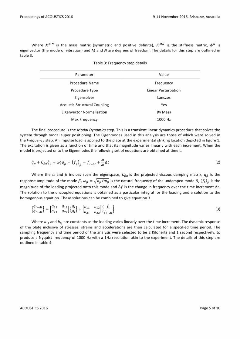
Where 𝑀!" is the mass matrix (symmetric and positive definite), 𝐾!" is the stiffness matrix, 𝜙! iseigenvector(themodeofvibration)andMandNaredegreesoffreedom.Thedetailsforthisstepareoutlinedintable3.
Table3:Frequencystepdetails
Parameter Value
ProcedureName Frequency
ProcedureType LinearPerturbation
Eigensolver Lanczos
Acoustic-StructuralCoupling Yes
EigenvectorNormalisation ByMass
MaxFrequency 1000Hz
ThefinalprocedureistheModalDynamicsstep.Thisisatransientlineardynamicsprocedurethatsolvesthe
systemthroughmodalsuperpositioning.TheEigenmodesused in thisanalysisarethoseofwhichweresolved intheFrequencystep.Animpulseloadisappliedtotheplateattheexperimentalstrikinglocationdepictedinfigure1.Theexcitationisgivenasafunctionoftimeandthatitsmagnitudevarieslinearlywitheachincrement.WhenthemodelisprojectedontotheEigenmodesthefollowingsetofequationsareobtainedattimet.
𝑞𝛽 + 𝐶𝛽𝛼𝑞𝛼 + 𝜔𝛽
2𝑞𝛽 = 𝑓𝑡 𝛽= 𝑓𝑡−Δ𝑡 +
ΔfΔ𝑡Δ𝑡 (2)
Where the𝛼 and𝛽 indices span the eigenspace,𝐶!" is the projected viscous damping matrix, 𝑞! is the
responseamplitudeofthemode𝛽,𝜔! = 𝑘!/𝑚! isthenaturalfrequencyoftheundampedmode𝛽, 𝑓! ! isthemagnitudeoftheloadingprojectedontothismodeandΔ𝑓isthechangeinfrequencyoverthetimeincrementΔ𝑡.Thesolution to theuncoupledequations isobtainedasaparticular integral for the loadingandasolution to thehomogenousequation.Thesesolutionscanbecombinedtogiveequation3.
𝑞!!!"𝑞!!!" =
𝑎!! 𝑎!"𝑎!" 𝑎!!
𝑞!𝑞! + 𝑏!! 𝑏!"
𝑏!" 𝑏!!𝑓!
𝑓!!!" (3)
Where𝑎!" and𝑏!" areconstantsastheloadingvarieslinearlyoverthetimeincrement.Thedynamicresponse
of the plate inclusive of stresses, strains and accelerations are then calculated for a specified time period. Thesampling frequencyandtimeperiodof theanalysiswereselectedtobe2Kilohertzand1secondrespectively, toproduceaNyquistfrequencyof1000Hzwitha1Hzresolutionakintotheexperiment.Thedetailsofthisstepareoutlinedintable4.

9-11November2016,Brisbane,Australia ProceedingsofACOUSTICS2016
Page6of10 ACOUSTICS2016
Table4:Modaldynamicsstepdetails
Parameter Value
ProcedureName ModalDynamics
ProcedureType LinearPerturbation
TimePeriod 1s
TimeIncrement 0.0005s
CriticalDampingFraction 0.002
LoadType Impulse
LoadTime 0.005s
3.4 Interactions Interaction pairs have been created between the plate, flanges, backing plate, bolts and air cavity. The
interactions between the bolts, flanges and backing plateweremodelled as surface-to-surface contact with thefriction coefficientof steelon steel as0.05. The rubber gaskets are connected toboth theplateand the flangesusing the tieconstraint thatensuresconstantcontact.Theaircavity isconnectedtoasinglesurfaceof theplateusingthetieconstraint.Theairmeshisselectedastheslavesurfacesothatthenodeswillconformtomatchthedeformationoftheplatenodes.
3.5 Boundary Conditions And Loads Fixedboundaryconditionswereappliedtotheinterfacebetweentherubbergasketsandsteelflanges,bolts
andthe interfacebetweentheplateandthebolts.Applicationof thefixedboundarytotherubbergasketratherthantheplate introducesdampingattheboundaryconditionsthat iswhat isobservedexperimentally.Fixingtheboltssupressesthevibrationofthevirtuallyrigidsteelflangesandbackingplate. The impulse loadapplied in theModalDynamics stepwasdesignedas a ramp loadover a timeperiodof0.005seconds.Theintegraloftheimpulseloadyieldsatotalappliedforceof1Ntosimplifyfindingtheresponse.
4. RESULTS Thepurposeof this finiteelementmodelling is to characterize theeffectsofa staticpressure fieldon the
frequency responseofplate structures, inparticular a circularplatewith clampededges.Comparisonsaremadebetweentheexperimentalresultsandfiniteelementmodelfirstlyforambientconditionswithnopressurefieldtoensuregoodagreementisfoundandtohencevalidatethemodel.Comparisonsarethenmadeforthephenomenonobservedwithinthefrequencyresponseoftheplatewiththeapplicationofthestaticpressurefield.
4.1 Plate Response at Ambient Pressure Figure2showsthetransferaccelerancefunctionsfortheplaterigforbothexperimentalandfiniteelementmethods at ambient pressure conditions. Good agreement is found between the two methods up to the 8thresonantfrequencyinbothpeaklocationandresponsefunctionshape.

ProceedingsofACOUSTICS2016 9-11November2016,Brisbane,Australia
ACOUSTICS2016 Page7of10
Figure3:Transferaccelerancefromexperimentalandfiniteelementresultsatambientpressure
Table5detailsthecomparisonsoftheresonantfrequenciesforthefirst6peaks.Themodenumber(m,n)isalsogivenwheremandn represent thenumberofdiametralmodesandnumberofcircularmodes respectively.Generalised,mrepresentsthemodenumberwhilstnrepresentstheharmonicnumber.Thediscrepanciesbetweentheexperimentalresultsandfiniteelementmodelacrossthesepeaksrangedfrom0.58to3.82%,withanaverageof2.15%.Itcanbeseenthatthefiniteelementmodelcannotaccuratelymodeltheexperimentalresponsefunctionforhigherordermodesasitsaccuracydeclinesheavilybeyond800Hertz.Withtheexceptionofthemodelsplittingobservedintheexperimentalpeaksnumbered2and6,thecharacteristicsoftheresponsefunctionshapearealsomodeledaccurately.Thiscanbenoticedwhenobservingtheregionsbetweenpeaksaswellasthetrendinthepeakamplitudes themselves. This level of agreement validates the ability of the finite elementmodel to predict theresponseofthetestrigforthepressuresimulations.
Table5:Experimentalandfiniteelementresonantfrequencycomparison
Peak Mode Experimental(Hz) Numerical(Hz) Difference(%)
1 (0,1) 101 104 2.97
2 (1,1) 177,165 181 2.26
3 (2,1) 288 299 3.82
4 (0,2) 346 344 0.58
5 (3,1) 432 438 1.39
6 (1,2) 535,546 525 1.87

9-11November2016,Brisbane,Australia ProceedingsofACOUSTICS2016
Page8of10 ACOUSTICS2016
4.2 Plate Response With Applied Pressure The application of the static pressure field to one surface of the vibrating plate was found to producesignificantchangestothefrequencyresponsecharacteristicsforboththeexperimentalandfiniteelementmethods.Figures 3 and figure 4 depict the waterfall plots for the experimental and finite element transfer accelerancefunctionsrespectively,rangingfrom0Pascalto10Kilopascalin0.5Kilopascalincrements.
Through inspectiontheresonant frequenciesof theresponse functionscorrespondingto themodesof thevibratingplate areobserved to increase. This is as expected as the applicationof thepressureproduces tensionwithintheplate(Leissa,1969).Unliketheresultsfromthehydrostaticpressure(Saltmarshetal,2015),theresultsobtainedhereallowthedirectcomparisonwiththeoreticalpredictionaseachmodecanbeconfidentlyidentified.Table6summarisestheobservedresonantfrequencymovementswithpressure.
Figure4:Waterfallplotdepictingthevariationinthetransferaccelerancefortheexperimentalmeasurements
rangingfrom0kPato10kPain0.5kPaincrements

ProceedingsofACOUSTICS2016 9-11November2016,Brisbane,Australia
ACOUSTICS2016 Page9of10
Figure5:Waterfallplotdepictingthevariationinthetransferacceleranceforthefiniteelementsimulationranging
from0kPato10kPain0.5kPaincrements
Table6:Increasesinexperimentalandfiniteelementresonantfrequencycomparisonoveranairpressureincrease
of10kPa
Peak Mode ExperimentalShift(%) NumericalShift(%)
1 (0,1) 80.20 66.35
2 (1,1) 41.21,35.59 28.73
3 (2,1) 17.36 14.38
4 (0,2) 21.39 18.31
5 (3,1) 9.26 7.99
6 (1,2) 11.78,11.36 10.86

9-11November2016,Brisbane,Australia ProceedingsofACOUSTICS2016
Page10of10 ACOUSTICS2016
Thecomparisonbetweentheexperimentalandfiniteelementresultsshowsgoodagreementformodes3to6. The discrepancies found between the resonant frequency shifts for modes 1 and 2 are fairly considerable,howeverthetrendbetweenthedegreeofmovementofeachmodeis identical.Boththeexperimentalandfiniteelement results highlight that there is a clear dependence between the resonant frequencymovement and theassociatedmodenumber. It isobservedthatthere isadecreasingdependencywith increasingmodenumberm,whichisevidentwhencomparingtheshiftsharmonicmodes(0,2)and(1,2)withfundamentalmodes(2,1)and(3,1).
5. CONCLUSIONS It has been shown both experimentally and theoretically that the application of a static pressure field
producedbyanair cavity toonesurfaceofavibratingplate increases the resonant frequenciesof thestructure.Substantial increases were observed for relatively small pressures, however it is noted that the geometry andstiffness of the disc ultimately determine the subsequent stresses and strains produced in the plate. Thesepreliminaryresultshowevershowthecriticalityoftheseeffectsonthefrequencyresponseofplatestructures,andvalidatetheirtheoreticalcounterpartsproducedwithfiniteelementsoftwareABQUS.Furtherinvestigationintotheeffectsonthemodeshapes,theconsequentsoundradiatedpressureandthestrainproducedintheplatewillyieldanin-depthexperimentalandtheoreticalcharacterizationoftheeffectofpressurefieldsonthefrequencyresponseofvibratingstructures.
REFERENCES Brüel&Kjær,2015,PULSEVersion42,softwareprogram,Brüel&Kjær,Nærum,Denmark.
DassaultSystèmes,2014,ABAQUS6.14-1,softwareprogram,DassaultSystèmes,Vélizy-Villacoublay,France.
Leissa, A.W. (1969), Vibration of Plates, Scientific and Technical Information Division, National Aeronautics andSpaceAdministration,Washington.
Liu,W,etal(2010),‘Measurementofsoundradiationfromtorpedo-shapedstructuresubjecttoanaxialexcitation’,Proceedingsof20thInternationalCongressonAcoustics.Availablefrom:ICAdigitallibrary.[August2010].
Pan,JandMatthews,D(2011)‘Analysisofunderwatervibrationofatorpedo-shapedstructuresubjectedtoaxialexcitation’,ProceedingsofAcoustics2011,the2011ConferenceoftheAustralianAcousticalSociety.Availablefrom:AASdigitallibrary.[November2011].
MatthewsD,etal(2014),‘Adetailedexperimentalmodalanalysisofaclampedcircularplate’,ProceedingsofInterNoise2014,the2014ConferenceoftheAustralianAcousticalSociety.Availablefrom:AASdigitallibrary.[November2014].
SaltmarshK,(2014),‘Theeffectsofsoundradiationenvironmentonstructuralvibration’,Honoursthesis,SchoolofMechanicalandCivilEngineering,TheUniversityofWesternAustralia.
SaltmarshK,etal(2015),‘Effectofwaterpressureonthefrequencyresponseofathinrigidlyclampedplate’,inYZhou,A.DLucey,YLiuandLHuang(eds),FSSIC2015:Fluid-Structure-SoundInteractionandControl;“Proceedingsofthe3rdSymposiumonFSSIC”,CurtinUniversity,Perth,WesternAustralia,pp.89-94.