Combined operation of UPQC with Distributed Generation to ...
Upload
gadam-siva-charan-dasCategory
view
33download
2description

A Project Report On
A NOVEL STRUCTURE FOR THREE-PHASE FOUR-
WIRE DISTRIBUTION SYSTEM UTILIZING UNIFIED
POWER QUALITY CONDITIONER (UPQC)
Submitted to
Jawaharlal Nehru Technological University Ananthapur,
Ananthapuramu.
in partial fulfillment of the requirements
For the award of the degree of
Bachelor of Technology
In
Electrical & Electronics Engineering
By
Gufran Ali Ahamed Syed (108Z1A0220)
Anwesh Katakam (108Z1A0204)
Chaitanya Rangani (108Z1A0210)
Kranti Kiran (108Z1A0230)
Under the esteemed guidance of
Ch. Lenin Babu, M.Tech, MISTE, MIAENG
Assistant Professor
Dept. Of EEE
Department of Electrical & Electronics Engineering
PRIYADARSHINI INSTITUTE OF TECHNOLOGY (Affiliated to Jawaharlal Nehru Technological University Anantapur, ANANTAPURAMU)
Kanuparthipadu, Nellore-524004
(2010-2014)

PRIYADARSHINI INSTITUTE OF TECHNOLOGY (Affiliated to Jawaharlal Nehru Technological University Anantapur, ANANTAPURAMU)
Kanuparthipadu, Nellore-524004
DEPARTMENT OF ELECTRICAL & ELECTRONICS ENGINEERING
Certificate
This is to certify that the Project entitled
A NOVEL STRUCTURE FOR THREE-PHASE FOUR-
WIRE DISTRIBUTION SYSTEM UTILIZING UNIFIED
POWER QUALITY CONDITIONER (UPQC)
Is the bonafide work done by
In the Department of Electrical and Electronics Engineering, Priyadarshini
Institute of Technology, SPSR Nellore and is submitted to Jawaharlal Nehru
Technological University Anantapur, Anantapuramu, in partial fulfillments of the
requirements for the award of B. Tech Degree in Electrical and Electronics
Engineering.
This work has been carried out under my guidance
Gufran Ali Ahamed Syed (108Z1A0220)
Anwesh Katakam (108Z1A0204)
Chaitanya Rangani (108Z1A0210)
Kranti Kiran (108Z1A0230)
Guide:
Ch. Lenin Babu, M. Tech, MISTE, MIAENG
Asst. Professor,
Department of E.E.E.
H.O.D.:
G. Venkata Narayana, M. Tech
Assoc. Professor,
Department of E.E.E.
Internal Examiner External Examiner

(i)
Acknowledgement
We are deeply indebted to our supervisor Mr. Ch. Lenin Babu, M.Tech, MISTE,
MIAENG, Associate Professor, Department of Electrical and Electronics
Engineering for valuable guidance, constant encouragement, constructive criticism
and keen interest evinced throughout the course of our work. We are really fortunate
to associate ourselves with such an advising and helping guide in every possible way,
at all stages, for the successful completion of this Project work.
We express our deep sense of gratitude and thanks to Mr. G. Venkata
Narayana, M. Tech, Associate Professor and Head of the Department, Dept. Of
Electrical and Electronics Engineering, for supporting in completing our Project
work.
We express our gratitude to our Principal Prof. Dr. Prasad H. K. P, Ph.D., and
the Management for providing all the facilities and supporting in completing our
Project work successfully. We express heartfelt thanks to all our Teachers in the
EEE department of Priyadarshini Institute of Technology for their moral support
and good wishes.
Finally we have a notation to express sincere thanks to our friends, one and all
those who guided, inspired and helped us in the completion of our Project work
successfully.
Project Associates
Gufran Ali Ahamed Syed (108Z1A0220)
Anwesh Katakam (108Z1A0204)
Chaitanya Rangani (108Z1A0210)
Kranti Kiran (108Z1A0230)

(ii)
Declaration
We hereby declare that our Project report entitled, “A Novel Structure for Three-Phase
Four-Wire Distribution System Utilizing Unified Power Quality Conditioner (UPQC),” being
submitted by us for award of Degree of Bachelor of Technology in ELECTRICAL &
ELECTRONICS ENGINEERING, to Jawaharlal Nehru Technological University Anantapur,
Anantapuramu and is a bonafied record of work done in PRIYADARSHINI INSTITUTE OF
TECHNOLOGY, SPSR NELLORE and has not been submitted to any other courses or
University for award of any degree.
Project Associates
Gufran Ali Ahamed Syed (108Z1A0220)
Anwesh Katakam (108Z1A0204)
Chaitanya Rangani (108Z1A0210)
Kranti Kiran (108Z1A0230)

(iii)
Abstract
This project deals with a novel structure for a three phase four-wire
distribution system utilizing Unified Power Quality Conditioner (UPQC).
Synchronization of the voltage frequency and phase allows electrical systems to
function in their intended manner without significant loss of performance or life. The
term is used to describe electric power that drives an electrical load and the load's
ability to function properly. Without the proper power, an electrical device (or load)
may malfunction, fail prematurely or not operate at all. There are many ways in which
electric power can be of poor quality and many more causes of such poor quality
power. Power quality determines the fitness of electrical power to consumer devices.
In this project, a Three-Phase Four-Wire system is realized from a Three-Phase
Three-Wire system where the neutral of series transformer used in series part of
UPQC is considered as the fourth wire for the Three-Phase Four-Wire system. A new
control strategy to balance the unbalanced load currents is also done and presented in
this document. The neutral current that may flow towards transformer’s neutral point
is compensated by using a four-leg voltage source inverter topology for shunt part.
Thus, the series transformer’s neutral will be at virtual zero potential during all
operating conditions. The simulation results based on MATLAB/Simulink are
presented to show the effectiveness of the proposed UPQC-based Three-Phase Four-
Wire distribution system.

Contents
Page.
No. Acknowledgement i
Declaration ii
Abstract iii
List of Figures vi-viii
List of Tables ix
Chapter 1 Introduction…………………………………... 02-05
1.1 Distribution Systems…………………………………... 02 1.2 History of Power Quality Conditioning……………….. 04
1.3 Outline of Project……………………………………… 05
Chapter 2 Power Quality………………………………… 07-13
2.1 Introduction……………………………………………. 07
2.2 Power Quality Problems……………………………….. 08
2.3 Power quality can be improved through……………….. 09
2.4 Benefits of Power Quality……………………………... 10
Chapter 3 FACTS Devices in Distribution System…….. 15-21
3.1 Introduction……………………………………………. 15
3.2 FACTS Devices used in Distribution for Power
Conditioning……………………………………………. 18
Chapter 4 P-Q Theory…………………………………… 23-26
4.1 Introduction……………………………………………. 23
4.2 P-Q Theory Power Components……………………….. 23
Chapter 5 Pulse Width Modulation……………………... 28-32
5.1 Introduction…………………………………………….. 28
5.2 Sinusoidal Pulse Width Modulation…………………… 29
Chapter 6 Voltage Source Inverter……………………… 34-38
6.1 Introduction…………………………………………….. 34
6.2 General Structure of Voltage Source Inverters………… 34
Chapter 7 Active Power Filters………………………….. 40-43
7.1 Introduction…………………………………………….. 40
7.2 Types of Active Power Filters…………………………. 41

Chapter 8 Modelling of Test System…………………….. 45-52
8.1 Three Phase Four Wire Distribution System Utilizing
UPQC …………………………………………………. 45
8.2 UPQC Controller……………………………………….. 47
Chapter 9 MATLAB Design and Simulation of Test
Results…………………………………………. 54-77 9.1 UPQC to R Load……………………………………….. 54 9.2 UPQC to RL Load……………………………………… 60 9.3 UPQC to RLC Load……………………………………. 66
9.4 UPQC TO IM LOAD…………………………………... 72
Chapter 10 Conclusion and Future Scope………………... 79-80
10.1 Conclusion……………………………………………… 79
10.2 Future Scope……………………………………………. 79
References 82
(vi)
List of Figures
S.NO NAME OF THE FIGURES PAGE. NO
3.1 Operational limits of transmission lines for different voltage levels 16
3.2 Overview of major FACTS-devices 17
3.3 Classification of Distribution Power Conditioners 18
3.4 A Schematic diagram of DVR 19
3.5 Schematic diagram of DSTATCOM 20
3.6 Schematic diagram of UPQC 21
4.1 p-q theory power components 26
5.1 Simple Voltage Sourced Inverter 29
5.2 Principal of Pulse Width Modulation 30
5.3 SPWM with fc/fm = 48, L/R = T/3 31
5.4 Over Modulation: m = 1.3 32
6.1 Principal of Pulse Width Modulation 37
7.1 Generalized block diagram for active power filters 40
7.2 Active power filter topologies implemented with PWM VSI.
(a) Shunt active power filter.
(b) Series active power filter.
(c) Hybrid active power filter. 42
8.1 3P4W distribution system: neutral provided from generation station 45
8.2 3P4W distribution system: neutral provided from Δ–Y transformer 45
8.3. 3P3W UPQC structure 46
8.4. Proposed 3P4W system realized from a 3P3W system utilizing UPQC 47
8.5 Shunt active filter control block diagram.
(a) Proposed balanced per-phase fundamental active power estimation.
(b) DC-link voltage control loop.
(c) Reference source current generation.
(d) Neutral current compensation. 52

(vii)
9.1. MATLAB model of UPQC for R Load 54
9.2. Utility Voltage (VS_abc) in UPQC2R Load 54
9.3. Load voltage (VL_abc) in UPQC2R Load 55
9.4. Injected Voltage (Vinj_abc) in UPQC2R Load 55
9.5. DC-link Voltage (Vdc) in UPQC2R Load 56
9.6. Load Current (IL_abc) in UPQC2R Load 56
9.7. Source Current (IS_abc) in UPQC2R Load 57
9.8. Shunt Compensating Current (ISh_abc) in UPQC2R Load 57
9.9. Current flowing through load neutral wire (IL_n) in UPQC2R Load 58
9.10. Shunt neutral compensating current (ISh_n) in UPQC2R Load 58
9.11. Neutral current flowing towards series transformer (ISr_n)
in UPQC2R Load 59
9.12. MATLAB model of UPQC for RL Load 60
9.13. Utility Voltage (VS_abc) in UPQC2RL Load 60
9.14. Load voltage (VL_abc) in UPQC2RL Load 61
9.15. Injected Voltage (Vinj_abc) in UPQC2RL Load 61
9.16. DC-link Voltage (Vdc) in UPQC2RL Load 62
9.17. Load Current (IL_abc) in UPQC2RL Load 62
9.18. Source Current (IS_abc) in UPQC2RL Load 63
9.19. Shunt Compensating Current (ISh_abc) in UPQC2RL Load 63
9.20. Current flowing through load neutral wire (IL_n) in UPQC2RL Load 64
9.21. Shunt neutral compensating current (ISh_n) in UPQC2RL Load 64
9.22. Neutral current flowing towards series transformer (ISr_n)
in UPQC2RL Load 65
9.23. MATLAB model of UPQC for RLC Load 66
9.24. Utility Voltage (VS_abc) in UPQC2RLC Load 66

(viii)
9.25. Load voltage (VL_abc) in UPQC2RLC Load 67
9.26. Injected Voltage (Vinj_abc) in UPQC2RLC Load 67
9.27. DC-link Voltage (Vdc) in UPQC2RLC Load 68
9.28. Load Current (IL_abc) in UPQC2RLC Load 68
9.29. Source Current (IS_abc) in UPQC2RLC Load 69
9.30. Shunt Compensating Current (ISh_abc) in UPQC2RLC Load 69
9.31. Current flowing through load neutral wire (IL_n) in UPQC2RLC Load 70
9.32. Shunt neutral compensating current (ISh_n) in UPQC2RLC Load 70
9.33. Neutral current flowing towards series transformer (ISr_n)
in UPQC2RLC Load 71
9.34. MATLAB model of UPQC for IM Load 72
9.35. Utility Voltage (VS_abc) in UPQC2IM Load 72
9.36. Load voltage (VL_abc) in UPQC2IM Load 73
9.37. Injected Voltage (Vinj_abc) in UPQC2IM Load 73
9.38. DC-link Voltage (Vdc) in UPQC2IM Load 74
9.39. Load Current (IL_abc) in UPQC2IM Load 74
9.40. Source Current (IS_abc) in UPQC2IM Load 75
9.41. Shunt Compensating Current (ISh_abc) in UPQC2IM Load 75
9.42. Current flowing through load neutral wire (IL_n) in UPQC2IM Load 76
9.43. Shunt neutral compensating current (ISh_n) in UPQC2IM Load 76
9.44. Neutral current flowing towards series transformer (ISr_n)
in UPQC2IM Load 77

(ix)
List of Tables
Table No. Name of Table Page. No.
7.1 Active filter solutions to power quality problems 43

Chapter 1
Introduction

Dept. of EEE
2 | P a g e
1. Introduction
1.1 Distribution Systems In recent years, the total number of distributed generation such as photovoltaic
generation system and wind power generator system connected to the distribution system
has been increasing because of the reduction of effects on the environment in Japan. In
the distribution system, it is necessary to keep reliability of power and power quality.
However, the harmonic troubles in a distribution system are apprehended in the
background of the increase of connection of DGs through the inverters and the spread of
the power electronics equipment. So far, the authors had studied the influence which
harmonics generated from DGs has on harmonics of distribution network and the restraint
method of harmonics in a distribution system by active filters. In this paper, the authors
propose a restraint method of voltage total harmonic distortion in a whole distribution
system by active filters operation of distributed generation with inverter.
Electricity distribution is the final stage in the delivery of electricity to end users.
A distribution system's network carries electricity from the transmission system and
delivers it to consumers. Typically, the network would include medium-voltage (2kV to
34.5kV) power lines, substations and pole-mounted transformers, low-voltage (less than
1 kV) distribution wiring such as a Service Drop and sometimes meters.
The electric power industry comprises electricity generation (AC power), electric
power transmission and ultimately electricity distribution to an electricity meter located
at the premises of the end user of the electric power. The electricity then moves through
the wiring system of the end user until it reaches the load. The complexity of the system
to move electric energy from the point of production to the point of consumption
combined with variations in weather, generation, demand and other factors provide many
opportunities for the quality of supply to be compromised.
The modern distribution system begins as the primary circuit leaves the sub-
station and ends as the secondary service enters the customer's meter socket by way of a
service drop. Distribution circuits serve many customers. The voltage used is appropriate
for the shorter distance and varies from 2,300 to about 35,000 volts depending on utility
standard practice, distance, and load to be served. Distribution circuits are fed from a

Dept. of EEE
3 | P a g e
transformer located in an electrical substation, where the voltage is reduced from the high
values used for power transmission.
Conductors for distribution may be carried on overhead pole lines, or in densely
populated areas, buried underground. Urban and suburban distribution is done with three-
phase systems to serve residential, commercial, and industrial loads. Distribution in rural
areas may be only single-phase if it is not economical to install three-phase power for
relatively few and small customers.
Only large consumers are fed directly from distribution voltages; most utility
customers are connected to a transformer, which reduces the distribution voltage to the
relatively low voltage used by lighting and interior wiring systems. The transformer may
be pole-mounted or set on the ground in a protective enclosure. In rural areas a pole-
mount transformer may serve only one customer, but in more built-up areas multiple
customers may be connected. In very dense city areas, a secondary network may be
formed with many transformers feeding into a common bus at the utilization voltage.
Each customer has a service drop connection and a meter for billing. (Some very small
loads, such as yard lights, may be too small to meter and so are charged only a monthly
rate.)
A ground connection to local earth is normally provided for the customer's system
as well as for the equipment owned by the utility. The purpose of connecting the
customer's system to ground is to limit the voltage that may develop if high voltage
conductors fall down onto lower-voltage conductors which are usually mounted lower to
the ground, or if a failure occurs within a distribution transformer. If all conductive
objects are bonded to the same earth grounding system, the risk of electric shock is
minimized.
However, multiple connections between the utility ground and customer ground
can lead to stray voltage problems; customer piping, swimming pools or other equipment
may develop objectionable voltages. These problems may be difficult to resolve since
some of them often originate from places other than the customer's premises. But many
problems occur in the quality of power too. Voltage sags, voltage swells, interruptions of
power, Harmonics etc. So, to tackle these problems of Power Quality, a new method for

Dept. of EEE
4 | P a g e
Three Phase Four Wire Distribution System was developed Using Unified Power Quality
Conditioner (UPQC), which is discussed in this thesis.
1.2 History of Power Quality Conditioning Both electric utilities and end users of electric power are becoming increasingly
concerned about the quality of electric power. The term power quality has become one of
the most prolific buzzwords in the power industry since the late 1980s. It is an umbrella
concept for a multitude of individual types of power system disturbances. The issues that
fall under this umbrella are not necessarily new. What is new is that engineers are now
attempting to deal with these issues using a system approach rather than handling them as
individual problems.
There are four major reasons for the increased concern:
1. Newer-generation load equipment, with microprocessor-based controls and
power electronic devices, is more sensitive to power quality variations than was
equipment used in the past.
2. The increasing emphasis on overall power system efficiency has resulted in
continued growth in the application of devices such as high-efficiency, adjustable-speed
motor drives and shunt capacitors for power factor correction to reduce losses. This is
resulting in increasing harmonic levels on power systems and has many people concerned
about the future impact on system capabilities.
3. End users have an increased awareness of power quality issues. Utility
customers are becoming better informed about such issues as interruptions, sags, and
switching transients and are challenging the utilities to improve the quality of power
delivered.
4. Many things are now interconnected in a network. Integrated processes mean
that the failure of any component has much more important consequences.
To overcome these power quality problems, power conditioning methods were
developed using FACTS (Flexible AC Transmission System). In FACTS, there are
different types of devices that are used for power conditioning. Some of these devices are
Dynamic Voltage Restorer (DVR), STATCOM (STATic synchronous COMpensator),
SVC (Static VAR Compensator), Unified Power Quality Conditioner(UPQC), Unified

Dept. of EEE
5 | P a g e
Power Flow Controller (UPFC) etc. Here in this project we have made use of UPQC for a
Three Phase Four Wire Distribution System.
1.3 Outline of Project The use of sophisticated equipment/loads at transmission and distribution level
has increased considerably in recent years due to the development in the semiconductor
device technology. The equipment needs clean power in order to function properly. At
the same time, the switching operation of these devices generates current harmonics
resulting in a polluted distribution system. The power-electronics-based devices have
been used to overcome the major power quality problems. To provide a balance,
distortion-free, and constant magnitude power to sensitive load and, at the same time, to
restrict the harmonic, unbalance, and reactive power demanded by the load and hence to
make the overall power distribution system more healthy, the unified power quality
conditioner (UPQC) is one of the best solutions.
A three-phase four-wire (3P4W) distribution system can be realized by providing
the neutral conductor along with the three power lines from generation station or by
utilizing a delta-star (Δ–Y) transformer at distribution level. The UPQC installed for
3P4W application generally considers 3P4W supply. This paper proposes a new
topology/structure that can be realized in UPQC-based applications, in which the series
transformer neutral used for series inverter, can be used to realize a 3P4W system even if
the power supplied by utility is three phase three-wire (3P3W). This new functionality
using UPQC could be useful in future UPQC-based distribution systems. The unbalanced
load currents are very common and yet an important problem in 3P4W distribution
system. This paper deals with the unbalanced load current problem with a new control
approach, in which the fundamental active powers demanded by each phase are
computed first, and these active powers are then redistributed equally on each of the
phases.

Chapter 2
Power Quality
Dept. of EEE
7 | P a g e
2. Power Quality
2.1 Introduction Both electric utilities and end users of electric power are becoming increasingly
concerned about the quality of electric power. The term power quality has become one of
the most prolific buzzwords in the power industry since the late 1980s. It is an umbrella
concept for a multitude of individual types of power system disturbances. The issues that
fall under this umbrella are not necessarily new. What is new is that engineers are now
attempting to deal with these issues using a system approach rather than handling them as
individual problems.
There are four major reasons for the increased concern:
1. Newer-generation load equipment, with microprocessor-based controls and
power electronic devices, is more sensitive to power quality variations than was
equipment used in the past.
2. The increasing emphasis on overall power system efficiency has resulted in
continued growth in the application of devices such as high-efficiency, adjustable-speed
motor drives and shunt capacitors for power factor correction to reduce losses. This is
resulting in increasing harmonic levels on power systems and has many people concerned
about the future impact on system capabilities.
3. End users have an increased awareness of power quality issues. Utility
customers are becoming better informed about such issues as interruptions, sags, and
switching transients and are challenging the utilities to improve the quality of power
delivered.
4. Many things are now interconnected in a network. Integrated processes mean
that the failure of any component has much more important consequences.
In distribution system power quality is important. As power quality problem is
defined as a problem manifested in voltage, current, or frequency deviations that results
in failure or misoperation of customer equipment, it has more to do with the distribution
system as distribution system is the connecting segment of power system and consumers.

Dept. of EEE
8 | P a g e
2.2 Power Quality Problems For the purpose of this article, we shall define power quality problems as:
‘Any power problem that results in failure or improper operation of customer equipment
manifests itself as an economic burden to the user, or produces negative impacts on the
environment.’
When applied to the container crane industry, the power issues which degrade power
quality include:
• Power Factor
• Harmonic Distortion
• Voltage Transients
• Voltage Sags or Dips
• Voltage Swells
The AC and DC variable speed drives utilized on board container cranes are
significant contributors to total harmonic current and voltage distortion. Whereas SCR
phase control creates the desirable average power factor, DC SCR drives operate at less
than this. In addition, line notching occurs when SCR’s commutate, creating transient
peak recovery voltages that can be 3 to 4 times the nominal line voltage depending upon
the system impedance and the size of the drives. The frequency and severity of these
power system disturbances varies with the speed of the drive. Harmonic current injection
by AC and DC drives will be highest when the drives are operating at slow speeds. Power
factor will be lowest when DC drives are operating at slow speeds or during initial
acceleration and deceleration periods, increasing to its maximum value when the SCR’s
are phased on to produce rated or base speed. Above base speed, the power factor
essentially remains constant.
Unfortunately, container cranes can spend considerable time at low speeds as the
operator attempts to spot and land containers. Poor power factor places a greater kVA
demand burden on the utility or engine-alternator power source. Low power factor loads
can also affect the voltage stability which can ultimately result in detrimental effects on
the life of sensitive electronic equipment or even intermittent malfunction. Voltage
transients created by DC drive SCR line notching, AC drive voltage chopping, and high

Dept. of EEE
9 | P a g e
frequency harmonic voltages and currents are all significant sources of noise and
disturbance to sensitive electronic equipment.
It has been our experience that end users often do not associate power quality
problems with Container cranes, either because they are totally unaware of such issues or
there was no economic Consequence if power quality was not addressed. Before the
advent of solid-state power supplies, Power factor was reasonable, and harmonic current
injection was minimal. Not until the crane Population multiplied, power demands per
crane increased, and static power conversion became the way of life, did power quality
issues begin to emerge. Even as harmonic distortion and power Factor issues surfaced, no
one was really prepared.
Even today, crane builders and electrical drive System vendors avoid the issue
during competitive bidding for new cranes. Rather than focus on Awareness and
understanding of the potential issues, the power quality issue is intentionally or
unintentionally ignored. Power quality problem solutions are available. Although the
solutions are not free, in most cases, they do represent a good return on investment.
However, if power quality is not specified, it most likely will not be delivered.
2.3 Power quality can be improved through
• Power factor correction,
• Harmonic filtering,
• Special line notch filtering,
• Transient voltage surge suppression,
• Proper earthing systems.
In most cases, the person specifying and/or buying a container crane may not be fully
aware of the potential power quality issues. If this article accomplishes nothing else, we
would hope to provide that awareness.
In many cases, those involved with specification and procurement of container
cranes may not be cognizant of such issues, do not pay the utility billings, or consider it
someone else’s concern. As a result, container crane specifications may not include
definitive power quality criteria such as power factor correction and/or harmonic
filtering. Also, many of those specifications which do require power quality equipment

Dept. of EEE
10 | P a g e
do not properly define the criteria. Early in the process of preparing the crane
specification:
• Consult with the utility company to determine regulatory or contract
requirements that must be satisfied, if any.
• Consult with the electrical drive suppliers and determine the power quality
profiles that can be Expected based on the drive sizes and technologies proposed for the
specific project.
• Evaluate the economics of power quality correction not only on the present
situation, but consider the impact of future utility deregulation and the future
development plans for the terminal
2.4 Benefits of Power Quality
Power quality in the container terminal environment impacts the economics of the
terminal operation, affects reliability of the terminal equipment, and affects other
consumers served by the same utility service. Each of these concerns is explored in the
following paragraphs.
1. Economic Impact
The economic impact of power quality is the foremost incentive to container terminal
operators. Economic impact can be significant and manifest itself in several ways:
a. Power Factor Penalties
Many utility companies invoke penalties for low power factor on monthly
billings. There is no industry standard followed by utility companies. Methods of
metering and calculating power factor penalties vary from one utility company to the
next. Some utility companies actually meter kVAR usage and establish a fixed rate times
the number of kVAR-hours consumed. Other utility companies monitor kVAR demands
and calculate power factor. If the power factor falls below a fixed limit value over a
demand period, a penalty is billed in the form of an adjustment to the peak demand
charges.
A number of utility companies servicing container terminal equipment do not yet
invoke power factor penalties. However, their service contract with the Port may still
require that a minimum power factor over a defined demand period be met. The utility

Dept. of EEE
11 | P a g e
company may not continuously monitor power factor or kVAR usage and reflect them in
the monthly utility billings; however, they do reserve the right to monitor the Port service
at any time. If the power factor criteria set forth in the service contract are not met, the
user may be penalized, or required to take corrective actions at the user’s expense. One
utility company, which supplies power service to several east coast container terminals in
the USA, does not reflect power factor penalties in their monthly billings, however, their
service contract with the terminal reads as follows:
‘The average power factor under operating conditions of customer’s load at the
point where service is metered shall be not less than 85%. If below 85%, the customer
may be required to furnish, install and maintain at its expense corrective apparatus which
will increase the Power factor of the entire installation to not less than 85%. The
customer shall ensure that no excessive harmonics or transients are introduced on to the
[utility] system. This may require special power conditioning equipment or filters.
The Port or terminal operations personnel, who are responsible for maintaining
container cranes, or specifying new container crane equipment, should be aware of these
requirements. Utility deregulation will most likely force utilities to enforce requirements
such as the example above.
Terminal operators who do not deal with penalty issues today may be faced with
some rather severe penalties in the future. A sound, future terminal growth plan should
include contingencies for addressing the possible economic impact of utility deregulation.
b. System Losses
Harmonic currents and low power factor created by nonlinear loads, not only
result in possible power factor penalties, but also increase the power losses in the
distribution system. These losses are not visible as a separate item on your monthly utility
billing, but you pay for them each month. Container cranes are significant contributors to
harmonic currents and low power factor.
Based on the typical demands of today’s high speed container cranes, correction
of power factor alone on a typical state of the art quay crane can result in a reduction of
system losses that converts to a 6 to 10% reduction in the monthly utility billing. For
most of the larger terminals, this is a significant annual saving in the cost of operation.

Dept. of EEE
12 | P a g e
c. Power Service Initial Capital Investments
The power distribution system design and installation for new terminals, as well
as modification of systems for terminal capacity upgrades, involves high cost,
specialized, high and medium voltage equipment. Transformers, switchgear, feeder
cables, cable reel trailing cables, collector bars, etc. must be sized based on the kVA
demand. Thus cost of the equipment is directly related to the total kVA demand. As the
relationship above indicates, kVA demand is inversely proportional to the overall power
factor, i.e. a lower power factor demands higher kVA for the same kW load.
Container cranes are one of the most significant users of power in the terminal.
Since container cranes with DC, 6 pulse, SCR drives operate at relatively low power
factor, the total kVA demand is significantly larger than would be the case if power factor
correction equipment were supplied on board each crane or at some common bus location
in the terminal. In the absence of power quality corrective equipment, transformers are
larger, switchgear current ratings must be higher, feeder cable copper sizes are larger,
collector system and cable reel cables must be larger, etc.
Consequently, the cost of the initial power distribution system equipment for a
system which does not address power quality will most likely be higher than the same
system which includes power quality equipment.
2. Equipment Reliability
Poor power quality can affect machine or equipment reliability and reduce the life
of components. Harmonics, voltage transients, and voltage system sags and swells are all
power quality problems and are all interdependent.
Harmonics affect power factor, voltage transients can induce harmonics, the same
phenomena which create harmonic current injection in DC SCR variable speed drives are
responsible for poor power factor, and dynamically varying power factor of the same
drives can create voltage sags and swells. The effects of harmonic distortion, harmonic
currents, and line notch ringing can be mitigated using specially designed filters.
3. Power System Adequacy
When considering the installation of additional cranes to an existing power
distribution system, a power system analysis should be completed to determine the
adequacy of the system to support additional crane loads. Power quality corrective

Dept. of EEE
13 | P a g e
actions may be dictated due to inadequacy of existing power distribution systems to
which new or relocated cranes are to be connected.
In other words, addition of power quality equipment may render a workable
scenario on an existing power distribution system, which would otherwise be inadequate
to support additional cranes without high risk of problems.
4. Environment
No issue might be as important as the effect of power quality on our environment.
Reduction in system losses and lower demands equate to a reduction in the consumption
of our natural nm resources and reduction in power plant emissions. It is our
responsibility as occupants of this planet to encourage conservation of our natural
resources and support measures which improve our air quality.

Chapter 3
FACTS Devices in
Distribution System
Dept. of EEE
15 | P a g e
3. FACTS Devices in Distribution System
3.1. Introduction Flexible AC Transmission Systems, called FACTS, got in the recent years a well-
known term for higher controllability in power systems by means of power electronic
devices. Several FACTS-devices have been introduced for various applications
worldwide. A number of new types of devices are in the stage of being introduced in
practice.
In most of the applications the controllability is used to avoid cost intensive or
landscape requiring extensions of power systems, for instance like upgrades or additions
of substations and power lines. FACTS-devices provide a better adaptation to varying
operational conditions and improve the usage of existing installations. The basic
applications of FACTS-devices are:
• Power flow control,
• Increase of transmission capability,
• Voltage control,
• Reactive power compensation,
• Stability improvement,
• Power quality improvement,
• Power conditioning,
• Flicker mitigation,
• Interconnection of renewable and distributed generation and storages.
The usage of lines for active power transmission should be ideally up to the
thermal limits. Voltage and stability limits shall be shifted with the means of the several
different FACTS devices. It can be seen that with growing line length, the opportunity for
FACTS devices gets more and more important.

Dept. of EEE
16 | P a g e
The influence of FACTS-devices is achieved through switched or controlled shunt
compensation, series compensation or phase shift control. The devices work electrically
as fast current, voltage or impedance controllers. The power electronic allows very short
reaction times down to far below one second.
Fig. 3.1. Operational limits of transmission lines for different voltage levels
The development of FACTS-devices has started with the growing capabilities of
power electronic components. Devices for high power levels have been made available in
converters for high and even highest voltage levels. The overall starting points are
network elements influencing the reactive power or the impedance of a part of the power
system. Figure 3.2 shows a number of basic devices separated into the conventional ones
and the FACTS-devices.
For the FACTS side the taxonomy in terms of 'dynamic' and 'static' needs some
explanation. The term 'dynamic' is used to express the fast controllability of FACTS-
devices provided by the power electronics. This is one of the main differentiation factors
from the conventional devices. The term 'static' means that the devices have no moving
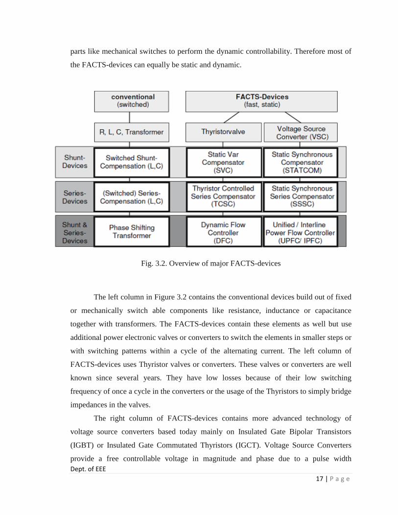
Dept. of EEE
17 | P a g e
parts like mechanical switches to perform the dynamic controllability. Therefore most of
the FACTS-devices can equally be static and dynamic.
Fig. 3.2. Overview of major FACTS-devices
The left column in Figure 3.2 contains the conventional devices build out of fixed
or mechanically switch able components like resistance, inductance or capacitance
together with transformers. The FACTS-devices contain these elements as well but use
additional power electronic valves or converters to switch the elements in smaller steps or
with switching patterns within a cycle of the alternating current. The left column of
FACTS-devices uses Thyristor valves or converters. These valves or converters are well
known since several years. They have low losses because of their low switching
frequency of once a cycle in the converters or the usage of the Thyristors to simply bridge
impedances in the valves.
The right column of FACTS-devices contains more advanced technology of
voltage source converters based today mainly on Insulated Gate Bipolar Transistors
(IGBT) or Insulated Gate Commutated Thyristors (IGCT). Voltage Source Converters
provide a free controllable voltage in magnitude and phase due to a pulse width

Dept. of EEE
18 | P a g e
modulation of the IGBTs or IGCTs. High modulation frequencies allow to get low
harmonics in the output signal and even to compensate disturbances coming from the
network. The disadvantage is that with an increasing switching frequency, the losses are
increasing as well. Therefore special designs of the converters are required to compensate
this.
3.2 FACTS Devices used in Distribution for Power Conditioning In distribution system, the FACTS devices used for power conditioning are
classified below in fig. 3.3.
Fig. 3.3. Classification of Distribution Power Conditioners
Power conditioning is essential for improving power quality. In fact, power
conditioning means improving of power quality. The devices that are used for power
conditioning at the distribution side of power system are mentioned in the above figure.
They are classified as:
A. DVR
B. DSTATCOM
C. UPQC

Dept. of EEE
19 | P a g e
A. DVR
DVR stands for Dynamic Voltage Restorer. It is used to correct Voltage Sags,
Voltage Swells, and Voltage Harmonics. A schematic diagram of Dynamic Voltage
Restorer is shown in the following fig. 3.4.
Fig. 3.4. A Schematic diagram of DVR
Dynamic Voltage Restoration (DVR) is a method and apparatus used to sustain,
or restore, an operational electric load during sags, or spikes, in voltage supply. Often
used in manufacturing areas requiring significant power to run tools/equipment, and
utility plants, this custom device mitigates potential damage to equipment and
undesirable slowdowns to the production line caused by an abrupt change in electric load.
This method uses critical devices such as an automatic Transfer switch and IGBT
Modules in order to operate. In normal conditions, the dynamic voltage restorer operates
in stand-by mode. However, during disturbances, nominal system voltage will be
compared to the voltage variation. This is to get the differential voltage that should be
injected by the DVR in order to maintain supply voltage to the load within limits.

Dept. of EEE
20 | P a g e
B. DSTATCOM
DSTATCOM stands for Distribution STATic synchronous COMpensator. It
compensates Reactive Current, Current Harmonics etc. A schematic diagram of
DTATCOM is shown in the following fig. 3.5.
Fig.3.5. Schematic diagram of DSTATCOM
Usually a STATCOM is installed to support electricity networks that have a poor power
factor and often poor voltage regulation. There are however, other uses, the most
common use is for voltage stability. A STATCOM is a voltage source converter (VSC)-
based device, with the voltage source behind a reactor. The voltage source is created from
a DC capacitor and therefore a STATCOM has very little active power capability.
However, its active power capability can be increased if a suitable energy storage device
is connected across the DC capacitor. The reactive power at the terminals of the
STATCOM depends on the amplitude of the voltage source. For example, if the terminal
voltage of the VSC is higher than the AC voltage at the point of connection, the
STATCOM generates reactive current; on the other hand, when the amplitude of the
voltage source is lower than the AC voltage, it absorbs reactive power. The response time
of a STATCOM is shorter than that of an SVC, mainly due to the fast switching times

Dept. of EEE
21 | P a g e
provided by the IGBTs of the voltage source converter. The STATCOM also provides
better reactive power support at low AC voltages than an SVC, since the reactive power
from a STATCOM decreases linearly with the AC voltage (as the current can be
maintained at the rated value even down to low AC voltage).
C. UPQC
UPQC stands for Unified Power Quality Conditioner. It compensates for Reactive
Current, Current Harmonics, Voltage Sags, Voltage Swells, Voltage Harmonics etc. A
schematic diagram of UPQC is shown in the following fig.3.6.
Fig. 3.6. Schematic diagram of UPQC
The provision of both DSTATCOM and DVR can control the power quality of the source
current and the load bus voltage. In addition, if the DVR and STATCOM are connected
on the DC side, the DC bus voltage can be regulated by the shunt connected
DSTATCOM while the DVR supplies the required energy to the load in case of the
transient disturbances in source voltage. The configuration of such a device (termed as
Unified Power Quality Conditioner (UPQC)) is shown in Fig. This is a versatile device
similar to a UPFC. However, the control objectives of a UPQC are quite different from
that of a UPFC.

Chapter 4
P-Q Theory
Dept. of EEE
23 | P a g e
4. P-Q Theory
4.1. Introduction
In 1983 Akagi et al. proposed a new theory for the control of active filters in
three-phase power systems called “Generalized Theory of the Instantaneous Reactive
Power in Three-Phase Circuits", also known as “Theory of Instantaneous Real Power and
Imaginary Power”, or “Theory of Instantaneous Active Power and Reactive Power”, or
“Theory of Instantaneous Power”, or simply as “p-q Theory”.
The theory was initially developed for three-phase three wire systems, with a brief
mention to systems with neutral wire. Later, Watanabe et al. and Aredes et al. extended it
to three-phase four-wire systems (systems with phases a, b, c and neutral wire). Since the
p-q theory is based on the time domain, it is valid both for steady-state and transient
operation, as well as for generic voltage and current waveforms, allowing the control of
the active filters in real-time. Another advantage of this theory is the simplicity of its
calculations, since only algebraic operations are required. The only exception is in the
separation of some power components in their mean and alternating values.
However, as it will be shown in this thesis, it is possible to exploit the
symmetries of the instantaneous power waveform for each specific power system,
achieving a calculation delay that can be as small as 1/6 and never greater than 1 cycle of
the power system frequency. It is also shown that calculations for reactive power and
zero-sequence compensation do not introduce any delay. Furthermore, it is possible to
associate physical meaning to the p-q theory power components, which eases the
understanding of the operation of any three-phase power system, balanced or unbalanced,
with or without harmonics.
4.2 P-Q Theory Power Components
The p-q theory implements a transformation from a stationary reference system in
a-b-c coordinates, to a system with coordinate’s α-β-0. It corresponds to an algebraic
transformation, known as Clarke transformation, which also produces a stationary
reference system, where coordinates α-β are orthogonal to each other, and coordinate 0
corresponds to the zero-sequence component.
Dept. of EEE
24 | P a g e
The zero sequence calculated here differs from the one obtained by the
symmetrical components transformation, or Fortes cue transformation, by a 3 factor. The
voltages and currents in α-β-0 coordinates are calculated as follows:
……………. (4.1)
Where,
………………………... (4.2)
The p-q theory power components are then calculated from voltages and currents in
the α-β-0 coordinates. Each component can be separated in its mean and alternating
values (see Fig. 1), which present physical meanings:
A. Instantaneous Zero-Sequence Power ( p0 )
…………… (4.3)
p0 − Mean value of the instantaneous zero-sequence power. It corresponds to the energy
per time unity that is transferred from the power source to the load through the zero-
sequence components of voltage and current.
-Alternating value of the instantaneous zero-sequence power. It means the energy per
time unity that is exchanged between the power source and the load through the zero-
sequence components of voltage and current.
The zero-sequence power exists only in three-phase systems with neutral wire.
Moreover, the systems must have both unbalanced voltages and currents, or the same
third morder harmonics, in both voltage and current, for at least one phase. It is important
to notice that cannot exist in a power system without the presence of . Since is

Dept. of EEE
25 | P a g e
clearly an undesired power component (it only exchanges energy with the load, and does
not transfer any energy to
the load), both and must be compensated.
B. Instantaneous Real Power ( p )
……………. (4.4)
-Mean value of the instantaneous real power. It corresponds to the energy per time
unity that is transferred from the power source to the load, in a balanced way, through the
a-b-c coordinates (it is, indeed, the only desired power component to be supplied by the
power source).
- Alternating value of the instantaneous real power. It is the energy per time unity that
is exchanged between the power source and the load, through the a-b-c coordinates.
Since does not involve any energy transference from the power source to load, it must
be compensated.
C. Instantaneous Imaginary Power ( q )
…………… (4.5)
- Mean value of instantaneous imaginary power.
- Alternating value of instantaneous imaginary power.
The instantaneous imaginary power, q, has to do with power (and corresponding
undesirable currents) that is exchanged between the system phases, and which does not
imply any transference or exchange of energy between the power source and the load.
Rewriting equation (4.5) in a-b-c coordinates the following expression is obtained:
………… (4.6)
This is a well-known expression used in conventional reactive power meters, in
power systems without harmonics and with balanced sinusoidal voltages. These
instruments, of the electro dynamic type, display the mean value of equation (4.6). The

Dept. of EEE
26 | P a g e
instantaneous imaginary power differs from the conventional reactive power, because in
the first case all the harmonics in voltage and current are considered. In the special case
of a balanced sinusoidal voltage supply and a balanced load, with or without harmonics,
is equal to the conventional reactive power
…………….(4.7)
Fig. 4.1. p-q theory power components
It is also important to note that the three-phase instantaneous power ( p3 ) can be
written in both coordinates systems, a-b-c and α-β-0, assuming the same value:
…………….. (4.8)
……………… (4.9)
Thus, to make the three-phase instantaneous power constant, it is necessary to
compensate the alternating power components and . Since, as seen before, it is not
possible to compensate only , all zero-sequence instantaneous power must be
compensated.
Moreover, to minimize the power system currents, the instantaneous imaginary
power, q, must also be compensated. The compensation of the p-q theory undesired
power components ( , p0 and q ) can be accomplished with the use of an active power
filter. The dynamic response of this active filter will depend on the time interval required
by its control system to calculate these values.

Chapter 5
Voltage Source Inverter

Dept. of EEE
28 | P a g e
5. Pulse Width Modulation
5.1 Introduction Pulse-width modulation (PWM), or pulse-duration modulation (PDM), is a
modulation technique that confirms the width of the pulse, formally the pulse duration,
based on modulator signal information. Although this modulation technique can be used
to encode information for transmission, its main use is to allow the control of the power
supplied to electrical devices, especially to inertial loads such as motors. In addition,
PWM is one of the two principal algorithms used in photovoltaic solar battery chargers,
the other being Maximum power point tracking (MPPT).
The average value of voltage (and current) fed to the load is controlled by turning
the switch between supply and load on and off at a fast pace. The longer the switch is on
compared to the off periods, the higher the power supplied to the load is.
The PWM switching frequency has to be much faster than what would affect the
load, which is to say the device that uses the power. Typically switching have to be done
several times a minute in an electric stove, 120 Hz in a lamp dimmer, from few kilohertz
(kHz) to tens of kHz for a motor drive and well into the tens or hundreds of kHz in audio
amplifiers and computer power supplies.
The term duty cycle describes the proportion of 'on' time to the regular interval or
'period' of time; a low duty cycle corresponds to low power, because the power is off for
most of the time. Duty cycle is expressed in percent, 100% being fully on.
The main advantage of PWM is that power loss in the switching devices is very
low. When a switch is off there is practically no current, and when it is on, there is almost
no voltage drop across the switch. Power loss, being the product of voltage and current, is
thus in both cases close to zero. PWM also works well with digital controls, which,
because of their on/off nature, can easily set the needed duty cycle.
A duty cycle is the percentage of one period in which a signal is active. A period
is the time it takes for a signal to complete an on-and-off cycle. As a formula, a duty
cycle may be expressed as:
D = (T/P) x100 %............(5.1)
Where D is the duty cycle, T is the time the signal is active, and P is the total
period of the signal. Thus, a 60% duty cycle means the signal is on 60% of the time but

Dept. of EEE
29 | P a g e
off 40% of the time. The "on time" for a 60% duty cycle could be a fraction of a second,
a day, or even a week, depending on the length of the period.
Duty cycles can be used to describe the percent time of an active signal in an
electrical device such as the power switch in a switching power supply
5.2 Sinusoidal Pulse Width Modulation The switches in the voltage source inverter (See Fig. 5.1) can be turned on and off
as required. In the simplest approach, the top switch is turned on If turned on and off only
once in each cycle, a square wave waveform results. However, if turned on several times
in a cycle an improved harmonic profile may be achieved.
Fig. 5.1. Simple Voltage Sourced Inverter
In the most straightforward implementation, generation of the desired output
voltage is achieved by comparing the desired reference waveform (modulating signal)
with a high-frequency triangular ‘carrier’ wave as depicted schematically in Fig.5.2.
Depending on whether the signal voltage is larger or smaller than the carrier waveform,
either the positive or negative dc bus voltage is applied at the output. Note that over the
period of one triangle wave, the average voltage applied to the load is proportional to the
amplitude of the signal (assumed constant) during this period.
The resulting chopped square waveform contains a replica of the desired
waveform in its low frequency components, with the higher frequency components being
at frequencies of a close to the carrier frequency. Notice that the root mean square value
of the ac voltage waveform is still equal to the dc bus voltage, and hence the total
harmonic distortion is not affected by the PWM process. The harmonic components are
merely shifted into the higher frequency range and are automatically filtered due to
inductances in the ac system. When the modulating signal is a sinusoid of amplitude Am,

Dept. of EEE
30 | P a g e
and the amplitude of the triangular carrier is Ac, the ratio m=Am/Ac is known as the
modulation index. Note that controlling the modulation index therefore controls the
amplitude of the applied output voltage.
With a sufficiently high carrier frequency (see Fig.5.3 drawn for fc/fm = 21 and t
= L/R = T/3; T = period of fundamental), the high frequency components do not
propagate significantly in the ac network (or load) due the presence of the inductive
elements. However, a higher carrier frequency does result in a larger number of
switching’s per cycle and hence in an increased power loss. Typically switching
frequencies in the 2-15 kHz range are considered adequate for power systems
applications. Also in three-phase systems it is advisable to use so
that all three waveforms are symmetric.
Fig. 5.2. Principal of Pulse Width Modulation

Dept. of EEE
31 | P a g e
Fig. 5.3. SPWM with fc/fm = 48, L/R = T/3
Note that the process works well for there are periods of the
triangle wave in which there is no intersection of the carrier and the signal as in Fig. 5.4.
However, a certain amount of this “over modulation” is often allowed in the interest of
obtaining a larger ac voltage magnitude even though the spectral content of the voltage is
rendered somewhat poorer.
Note that with an odd ratio for fc/fm, the waveform is anti-symmetric over a 360
degree cycle. With an even number, there are harmonics of even order, but in particular
also a small dc component. Hence an even number is not recommended for single phase
inverters, particularly for small ratios of fc/fm.

Dept. of EEE
32 | P a g e
Fig. 5.4. Over Modulation: m = 1.3

Chapter 6
Pulse Width Modulation

Dept. of EEE
34 | P a g e
6. Voltage Source Inverter
6.1 Introduction
A voltage source inverter (VSI) is one that takes in a fixed voltage from a device, such as
a dc power supply, and converts it to a variable-frequency AC supply. Voltage-source
inverters are divided into three general categories: Pulse-width Modulated (PWM)
Inverters, Square-wave Inverters, and Single-phase Inverters with Voltage Cancellation.
Pulse-width modulation inverters take in a constant dc voltage. Diode-rectifiers are used
to rectify the line voltage, and the inverter must control the magnitude and the frequency
of the ac output voltages. To do this the inverter uses pulse-width modulation using its
switches. There are different methods for doing the pulse-width modulation in an inverter
in order to shape the output ac voltages to be very close to a sine wave. These different
methods will be discussed further with a focus on sinusoidal-PWM. Squire-wave
inverters have their input connected to a controlled dc voltage in order to control the
magnitude of the output ac voltage.
The inverter only controls the frequency of the output where the input voltage is
controlled the magnitude. The output ac voltage has a waveform similar to a square wave
which is where the inverter got its name. Lastly, Single-phase inverters with voltage
cancellation take in a constant dc source and output a square-wave like ac voltage. They
can control both the frequency and the magnitude of the output but do not use PWM and
therefore have a square-wave like output. These inverters have combined characteristics
of the previous two inverters. The voltage cancellation only works with single phase
inverters, not three phases.
6.2 General Structure of Voltage Source Inverters
Figs. 6.1 (a) and 6.1(b) show the typical power-circuit topologies of a single-
phase and a three-phase voltage source inverter respectively. These topologies require
only a single dc source and for medium output power applications the preferred devices
are n-channel IGBTs. ‘Edc’ is the input dc supply and a large dc link capacitor (Cdc) is put
across the supply terminals. Capacitors and switches are connected to dc bus using short
Dept. of EEE
35 | P a g e
leads to minimize the stray inductance between the capacitor and the inverter switches.
Needless to say that physical layout of positive and negative bus lines is also important to
limit stray inductances. Q1, Q2, Q3 etc. are fast and controllable switches. D1, D2, D3 etc.
are fast recovery diodes connected in anti-parallel with the switches. ‘A’, ‘B’ and ‘C’ are
output terminals of the inverter that get connected to the ac load. A three-phase inverter
has three load-phase terminals whereas a single-phase inverter has only one pair of load
terminals.
The current supplied by the dc bus to the inverter switches is referred as dc link
current and has been shown as ‘idc’ in Figs 6.1(a) and 6.1(b). The magnitude of dc link
current often changes in step (and sometimes its direction also changes) as the inverter
switches are turned on and off. The step change in instantaneous dc link current occurs
even if the ac load at the inverter output is drawing steady power. However, average
magnitude of the dc link current remains positive if net power-flow is from dc bus to ac
load. The net power-flow direction reverses if the ac load connected to the inverter is
regenerating. Under regeneration, the mean magnitude of dc link current is negative.
The dc link current may conceptually be decomposed into its dc and ac
components. The individual roles of the ‘dc voltage source’ and the ‘dc link capacitor’
may be clearly seen with respect to the dc and ac components of the dc link current. For
the dc component of current the capacitor acts like open circuit. As expected, under
steady state, the capacitor does not supply any dc current. The dc part of bus current is
supplied solely by the dc source. A practical dc voltage source may have some resistance
as well as some inductance in series with its internal emf. For dc component of bus
current, the source voltage appears in series with its internal resistance (effect of source
inductance is not felt). But for ac component of current, the internal dc emf of source
appears as short and its series impedance (resistance in series with inductance) appears in
parallel with the dc-link capacitor. Thus the ac component of current gets divided into
these two parallel paths. However, the high frequency component of ac current mainly
flows through the capacitor, as the capacitive impedance is lower at high frequencies.
The step change in dc link current is associated with significant amount of high frequency
components of current that essentially finds its path through the capacitor.

Dept. of EEE
36 | P a g e
For an ideal input (dc) supply, with no series impedance, the dc link capacitor
does not have any role. However a practical voltage supply may have considerable
amount of output impedance. The supply line impedance, if not bypassed by a
sufficiently large dc link capacitor, may cause considerable voltage spike at the dc bus
during inverter operation. This may result in deterioration of output voltage quality, it
may also cause malfunction of the inverter switches as the bus voltage appears across the
non-conducting switches of the inverter. Also, in the absence of dc link capacitor, the
series inductance of the supply line will prevent quick build up or fall of current through
it and the circuit behaves differently from the ideal VSI where the dc voltage supply is
supposed to allow rise and fall in current as per the demand of the inverter circuit.
It may not be possible to reduce supply line inductance below certain limit. Most
dc supplies will inherently have rather significant series inductance, for example a
conventional dc generator will have considerable armature inductance in series with the
armature emf. Similarly, if the dc supply is derived after rectifying ac voltage, the ac
supply line inductance will prevent quick change in rectifier output current. The effect of
ac line inductance is reflected on the dc side as well, unless this inductance is effectively
bypassed by the dc side capacitor. Even the connecting leads from the dc source to the
inverter dc bus may contribute significantly to the supply line inductance in case the lead
lengths are large and circuit lay out is poor. It may be mentioned here that an inductance,
in series with the dc supply, may at times be welcome. The reason being that for some
types of dc sources, like batteries, it is detrimental to carry high frequency ripple current.
For such cases it is advantageous if the dc source has some series inductance. Due to
series inductance of the source, the high frequency ripple will prefer to flow through the
dc link capacitor and thus relieve the dc source.
The dc link capacitor should be put very close to the switches so that it provides a
low impedance path to the high frequency component of the switch currents. The
capacitor itself must be of good quality with very low equivalent series resistor (ESR)
and equivalent series inductor (ESL). The length of leads that interconnect switches and
diodes to the dc bus must also be minimum to avoid insertion of significant amount of
Dept. of EEE
37 | P a g e
stray inductances in the circuit. The overall layout of the power circuit has a significant
effect over the performance of the inverter circuit.
(a) (b)
(c)
Fig.6.1. (a) Topology of 1- Phase VSI; (b) Topology of a 3- Phase VSI
(c) Topology of a 1-Phase Half Bridge VSI
One of the thumb rules for good circuit layout is to put the conductor pairs
carrying same magnitude but opposite direction of currents close by, the minimum
distance between them being decided only by their voltage isolation requirement. Thus
the positive and negative terminals of the dc bus should run close by. A twisted wire pair
may be an example of two closely running wires.
Dept. of EEE
38 | P a g e
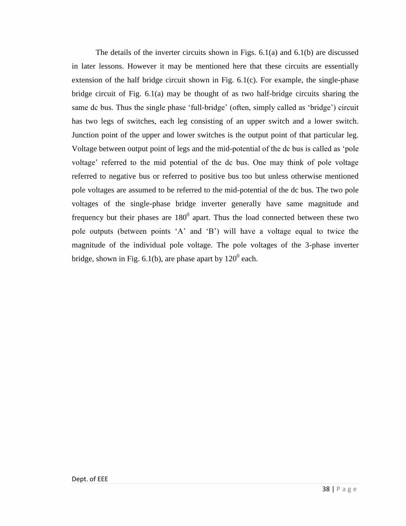
The details of the inverter circuits shown in Figs. 6.1(a) and 6.1(b) are discussed
in later lessons. However it may be mentioned here that these circuits are essentially
extension of the half bridge circuit shown in Fig. 6.1(c). For example, the single-phase
bridge circuit of Fig. 6.1(a) may be thought of as two half-bridge circuits sharing the
same dc bus. Thus the single phase ‘full-bridge’ (often, simply called as ‘bridge’) circuit
has two legs of switches, each leg consisting of an upper switch and a lower switch.
Junction point of the upper and lower switches is the output point of that particular leg.
Voltage between output point of legs and the mid-potential of the dc bus is called as ‘pole
voltage’ referred to the mid potential of the dc bus. One may think of pole voltage
referred to negative bus or referred to positive bus too but unless otherwise mentioned
pole voltages are assumed to be referred to the mid-potential of the dc bus. The two pole
voltages of the single-phase bridge inverter generally have same magnitude and
frequency but their phases are 1800 apart. Thus the load connected between these two
pole outputs (between points ‘A’ and ‘B’) will have a voltage equal to twice the
magnitude of the individual pole voltage. The pole voltages of the 3-phase inverter
bridge, shown in Fig. 6.1(b), are phase apart by 1200 each.

Chapter 7
Active Power Filters

Dept. of EEE
40 | P a g e
7. Active Power Filters
7.1 Introduction Active Filters are commonly used for providing harmonic compensation to a
system by controlling current harmonics in supply networks at the low to medium voltage
distribution level or for reactive power or voltage control at high voltage distribution
level. These functions may be combined in a single circuit to achieve the various
functions mentioned above or in separate active filters which can attack each aspect
individually. The block diagram presented in section shows the basic sequence of
operation for the active filter. This diagram shows various sections of the filter each
responding to its own classification.
The block diagram shown in figure represents the key components of a typical
active power filter along with their interconnections. The reference signal estimator
monitors the harmonic current from the nonlinear load along with information about
other system variables. The reference signal from the current estimator, as well as other
signals, drives the overall system controller. This in turn provides the control for the
PWM switching pattern generator. The output of the PWM pattern generator controls the
power circuit through a suitable interface. The power circuit in the generalized block
diagram can be connected in parallel, series or parallel/series configurations, depending
on the transformer used.
Fig. 7.1. Generalized block diagram for active power filters

Dept. of EEE
41 | P a g e
7.2 Types of Active Power Filters The technology of active power filter has been developed during the past two
decades reaching maturity for harmonics compensation, reactive power, and voltage
balance in ac power networks. All active power filters are developed with PWM
converters (current source or voltage source inverters). The current-fed PWM inverter
bridge structure behaves as a non-sinusoidal current source to meet the harmonic current
requirement of the nonlinear load. It has a self-supported dc reactor that ensures the
continuous circulation of the dc current. They present good reliability, but have important
losses and require higher values of parallel capacitor filters at the ac terminals to remove
unwanted current harmonics. Moreover, they cannot be used in multilevel or multistep
modes configurations to allow compensation in higher power ratings.
The other converter used in active power filter topologies is the voltage-source
PWM inverter. This converter is more convenient for active power filtering applications
since it is lighter, cheaper, and expandable to multilevel and multistep versions, to
improve its performance for high power rating compensation with lower switching
frequencies. The PWM voltage source inverter has to be connected to the ac mains
through coupling reactors. An electrolytic capacitor keeps a dc voltage constant and
ripple free.
Active power filters can be classified based on the type of converter, topology,
control scheme, and compensation characteristics. The most popular classification is
based on the topology such as shunt, series or hybrid. The hybrid configuration is a
combination of passive and active compensation. The different active power filter
topologies are shown in Fig.7.2
Shunt active power filters (Fig. 7.2 (a)) are widely used to compensate current
harmonics, reactive power and load current unbalanced. It can also be used as a static var
generator in power system networks for stabilizing and improving voltage profile. Series
active power filters (Fig.7.2 (b)) is connected before the load in series with the ac mains,
through a coupling transformer to eliminate voltage harmonics and to balance and
regulate the terminal voltage of the load or line. The hybrid configuration is a
combination of series active filter and passive shunt filter (Fig. 7.2 (c)). This topology is
very convenient for the compensation of high power systems, because the rated power of

Dept. of EEE
42 | P a g e
the active filter is significantly reduced (about 10% of the load size), since the major part
of the hybrid filter consists of the passive shunt LC filter used to compensate lower-order
current harmonics and reactive power.
(a) (b)
(c)
Fig. 7.2. Active power filter topologies implemented with PWMVSI.
(a) Shunt active power filter. (b) Series active power filter. (c) Hybrid active power filter.
Dept. of EEE
43 | P a g e
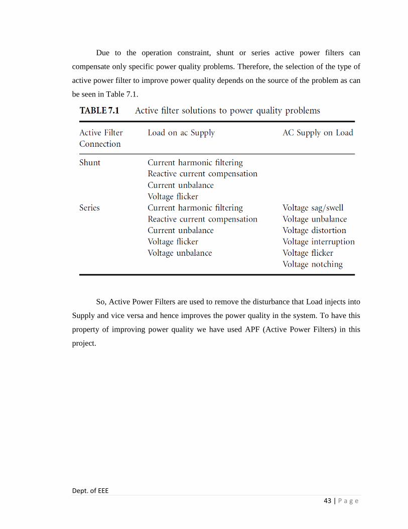
Due to the operation constraint, shunt or series active power filters can
compensate only specific power quality problems. Therefore, the selection of the type of
active power filter to improve power quality depends on the source of the problem as can
be seen in Table 7.1.
So, Active Power Filters are used to remove the disturbance that Load injects into
Supply and vice versa and hence improves the power quality in the system. To have this
property of improving power quality we have used APF (Active Power Filters) in this
project.

Chapter 8
Modelling of Test System

Dept. of EEE
45 | P a g e
8. Modelling of Test System
8.1 Three Phase Four Wire Distribution System Utilizing UPQC
Fig. 8.1. 3P4W distribution system: neutral provided from generation station.
Generally, a 3P4W distribution system is realized by providing a neutral
conductor along with three power conductors from generation station or by utilizing a
three-phase Δ–Y transformer at distribution level. Fig. 8.1 shows a 3P4W network in
which the neutral conductor is provided from the generating station itself, whereas Fig.
8.2 shows a 3P4W distribution network considering a Δ–Y transformer.
Assume a plant site where three-phase three-wire UPQC is already installed to
protect a sensitive load and to restrict any entry of distortion from load side toward
utility, as shown in Fig. 8.3. If we want to upgrade the system now from 3P3W to 3P4W
due to installation of some single-phase loads and if the distribution transformer is close
to the plant under consideration, utility would provide the neutral conductor from this
transformer without major cost involvement. In certain cases, this may be a costly
solution because the distribution transformer may not be situated in close vicinity.
Fig. 8.2. 3P4W distribution system: neutral provided from Δ–Y transformer.

Dept. of EEE
46 | P a g e
Recently, the utility service providers are putting more and more restrictions on
current total harmonic distortion (THD) limits, drawn by nonlinear loads, to control the
power distribution system harmonic pollution. At the same time, the use of sophisticated
equipment/load has increased significantly, and it needs clean power for its proper
operation. Therefore, in future distribution systems and the plant/load centers, application
of UPQC would be common. Fig. 8.4 shows the proposed novel 3P4W topology that can
be realized from a 3P3W system.
This proposed system has all the advantages of general UPQC, in addition to easy
expansion of 3P3W system to 3P4W system. Thus, the proposed topology may play an
important role in the future 3P4W distribution system for more advanced UPQC based
plant/load center installation, where utilities would be having an additional option to
realize a 3P4W system just by providing a 3P3W supply.
Fig. 8.3. 3P3W UPQC structure.
As shown in Fig. 8.3, the UPQC should necessarily consist of three-phase series
transformer in order to connect one of the inverters in the series with the line to function
as a controlled voltage source. If we could use the neutral of three-phase series
transformer to connect a neutral wire to realize the 3P4W system, then 3P4W system can
easily be achieved from a 3P3W system (Fig. 8.4). The neutral current, present if any,
would flow through this fourth wire toward transformer neutral point.
This neutral current can be compensated by using a split capacitor topology or a
four-leg voltage-source inverter (VSI) topology for a shunt inverter. The four-leg VSI
topology requires one additional leg as compared to the split capacitor topology. The

Dept. of EEE
47 | P a g e
neutral current compensation in the four-leg VSI structure is much easier than that of the
split capacitor because the split capacitor topology essentially needs two capacitors and
an extra control loop to maintain a zero voltage error difference between both the
capacitor voltages, resulting in a more complex control loop to maintain the dc bus
voltage at constant level.
Fig. 8.4. Proposed 3P4W system realized from a 3P3W system utilizing UPQC.
In this paper, the four-leg VSI topology is considered to compensate the neutral
current flowing toward the transformer neutral point. A fourth leg is added on the
existing 3P3W UPQC, such that the transformer neutral point will be at virtual zero
potential. Thus, the proposed structure would help to realize a 3P4W system from a
3P3W system at distribution load end. This would eventually result in easy expansion
from 3P3W to 3P4W systems. A new control strategy to generate balanced reference
source currents under unbalanced load condition is also proposed in this paper and is
explained in the next section.
8.2 UPQC Controller The control algorithm for series active power filter (APF) is based on unit vector
template generation scheme, whereas the control strategy for shunt APF is discussed in
this section. Based on the load on the 3P4W system, the current drawn from the utility
can be unbalanced. In this paper, a new control strategy is proposed to compensate the
current unbalance present in the load currents by expanding the concept of single phase

Dept. of EEE
48 | P a g e
p–q theory. According to this theory, a signal phase system can be defined as a pseudo
two-phase system by giving π/2 lead or π/2 lag, i.e., each phase voltage and current of the
original three-phase system can be considered as three independent two-phase systems.
These resultant two phase systems can be represented in α–β coordinates, and
thus, the p–q theory applied for balanced three-phase system can also be used for each
phase of unbalanced system independently. The actual load voltages and load currents are
considered as α-axis quantities, whereas the π/2 lead load or π/2 lag voltages and π/2 lead
or π/2 lag load currents are considered as β-axis quantities. In this document, π/2 lead is
considered to achieve a two-phase system for each phase.
The major disadvantage of p–q theory is that it gives poor results under distorted
and/or unbalanced input/utility voltages. In order to eliminate these limitations, the
reference load voltage signals extracted for series APF are used instead of actual load
voltages.
…………… (8.1)
……………………..….. (8.2)
Where represents the reference load voltage and VLm represents the desired load
voltage magnitude.
Similarly, for phase b, the load voltage and current in α–β coordinates can be represented
by π/2 lead as
……………… (8.3)

Dept. of EEE
49 | P a g e
……………………….…………. (8.4)
In addition, for phase c, the load voltage and current in α–β coordinates can be
represented by π/2 lead as
…………………… (8.5)
……………….. (8.6)
By using the definition of three-phase p–q theory for balanced three-phase system, the
instantaneous power components can be represented as
Instantaneous active power
pL,abc = vL,abc_α * iL,abc_β + vL,abc_β * iL,abc_α ………… (8.7)
Instantaneous reactive power
qL,abc = vL,abc_α * iL,abc_β - vL,abc_β * iL,abc_α ……….…… (8.8)
Considering phase a, the phase-a instantaneous load active and instantaneous load
reactive powers can be represented by
…………. (8.9)
Where
………… (8.10)
…………. (8.11)
In (10) and (11), and represent the dc components that are responsible for
fundamental load active and reactive powers, whereas and represent the ac
components that are responsible for harmonic powers. The phase-a fundamental
instantaneous load active and reactive power components can be extracted from PLa and
qLa, respectively, by using a low pass filter.
Therefore, the instantaneous fundamental load active power for phase a is given by
……………… (8.12)

Dept. of EEE
50 | P a g e
And the instantaneous fundamental load reactive power for phase a is given by
…………… (8.13)
Similarly, the fundamental instantaneous load active and the fundamental instantaneous
load reactive powers for phases b and c can be calculated as
Instantaneous fundamental load active power for phase b
……….. (8.14)
Instantaneous fundamental load reactive power for phase b
…….… (8.15)
Instantaneous fundamental load active power for phase c
……….. (8.16)
Instantaneous fundamental load reactive power for phase c
………… (8.17)
Since the load current drawn by each phase may be different due to different loads
that may be present inside plant, therefore, the instantaneous fundamental load active
power and instantaneous fundamental load reactive power demand for each phase may
not be the same. In order to make this load unbalanced power demand, seen from the
utility side, as a perfectly balanced fundamental three-phase active power, the unbalanced
load power should be properly redistributed between utility, UPQC, and load, such that
the total load seen by the utility would be linear and balanced load. The unbalanced or
balanced reactive power demanded by the load should be handled by a shunt APF.
The aforementioned task can be achieved by summing instantaneous fundamental
load active power demands of all the three phases and redistributing it again on each
utility phase, i.e., from (12), (14), and (16),
………… (8.18)
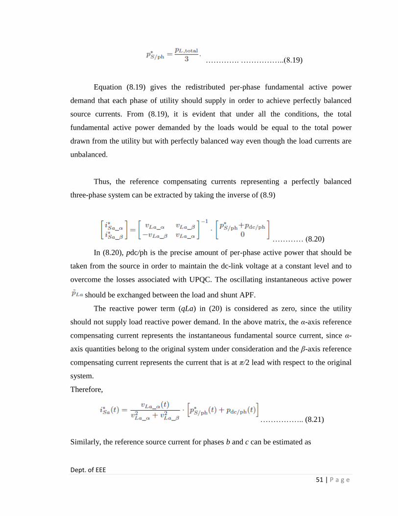
Dept. of EEE
51 | P a g e
…………. ……………..(8.19)
Equation (8.19) gives the redistributed per-phase fundamental active power
demand that each phase of utility should supply in order to achieve perfectly balanced
source currents. From (8.19), it is evident that under all the conditions, the total
fundamental active power demanded by the loads would be equal to the total power
drawn from the utility but with perfectly balanced way even though the load currents are
unbalanced.
Thus, the reference compensating currents representing a perfectly balanced
three-phase system can be extracted by taking the inverse of (8.9)
………… (8.20)
In (8.20), pdc/ph is the precise amount of per-phase active power that should be
taken from the source in order to maintain the dc-link voltage at a constant level and to
overcome the losses associated with UPQC. The oscillating instantaneous active power
should be exchanged between the load and shunt APF.
The reactive power term (qLa) in (20) is considered as zero, since the utility
should not supply load reactive power demand. In the above matrix, the α-axis reference
compensating current represents the instantaneous fundamental source current, since α-
axis quantities belong to the original system under consideration and the β-axis reference
compensating current represents the current that is at π/2 lead with respect to the original
system.
Therefore,
…………….. (8.21)
Similarly, the reference source current for phases b and c can be estimated as
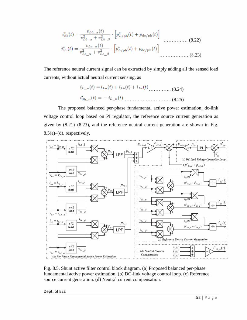
Dept. of EEE
52 | P a g e
…………… (8.22)
……………… (8.23)
The reference neutral current signal can be extracted by simply adding all the sensed load
currents, without actual neutral current sensing, as
………….. (8.24)
……………………….. (8.25)
The proposed balanced per-phase fundamental active power estimation, dc-link
voltage control loop based on PI regulator, the reference source current generation as
given by (8.21)–(8.23), and the reference neutral current generation are shown in Fig.
8.5(a)–(d), respectively.
Fig. 8.5. Shunt active filter control block diagram. (a) Proposed balanced per-phase
fundamental active power estimation. (b) DC-link voltage control loop. (c) Reference
source current generation. (d) Neutral current compensation.

Chapter 9
MATLAB Design and
Simulation of Test Results
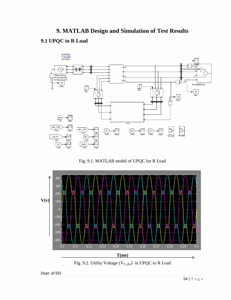
Dept. of EEE
54 | P a g e
9. MATLAB Design and Simulation of Test Results
9.1 UPQC to R Load
Fig. 9.1. MATLAB model of UPQC for R Load
V(v)
T(ms)
Fig. 9.2. Utility Voltage (VS_abc) in UPQC to R Load

Dept. of EEE
55 | P a g e
V(v)
T(ms)
Fig. 9.3. Load voltage (VL_abc) in UPQC to R Load
V(v)
T(ms)
Fig. 9.4. Injected Voltage (Vinj_abc) in UPQC to R Load

Dept. of EEE
56 | P a g e
V(v)
T(ms)
Fig. 9.5. DC-link Voltage (Vdc) in UPQC to R Load
I(A)
T(ms)
Fig. 9.6. Load Current (IL_abc) in UPQC to R Load

Dept. of EEE
57 | P a g e
I(A)
T(ms)
Fig.9.7. Source Current (IS_abc) in UPQC to R Load
I(A)
T(ms)
Fig. 9.8. Shunt Compensating Current (ISh_abc) in UPQC to R Load

Dept. of EEE
58 | P a g e
I(A)
T(ms)
Fig. 9.9. Current flowing through load neutral wire (IL_n) in UPQC to R Load
I(A)
T(ms)
Fig. 9.10. Shunt neutral compensating current (ISh_n) in UPQC to R Load
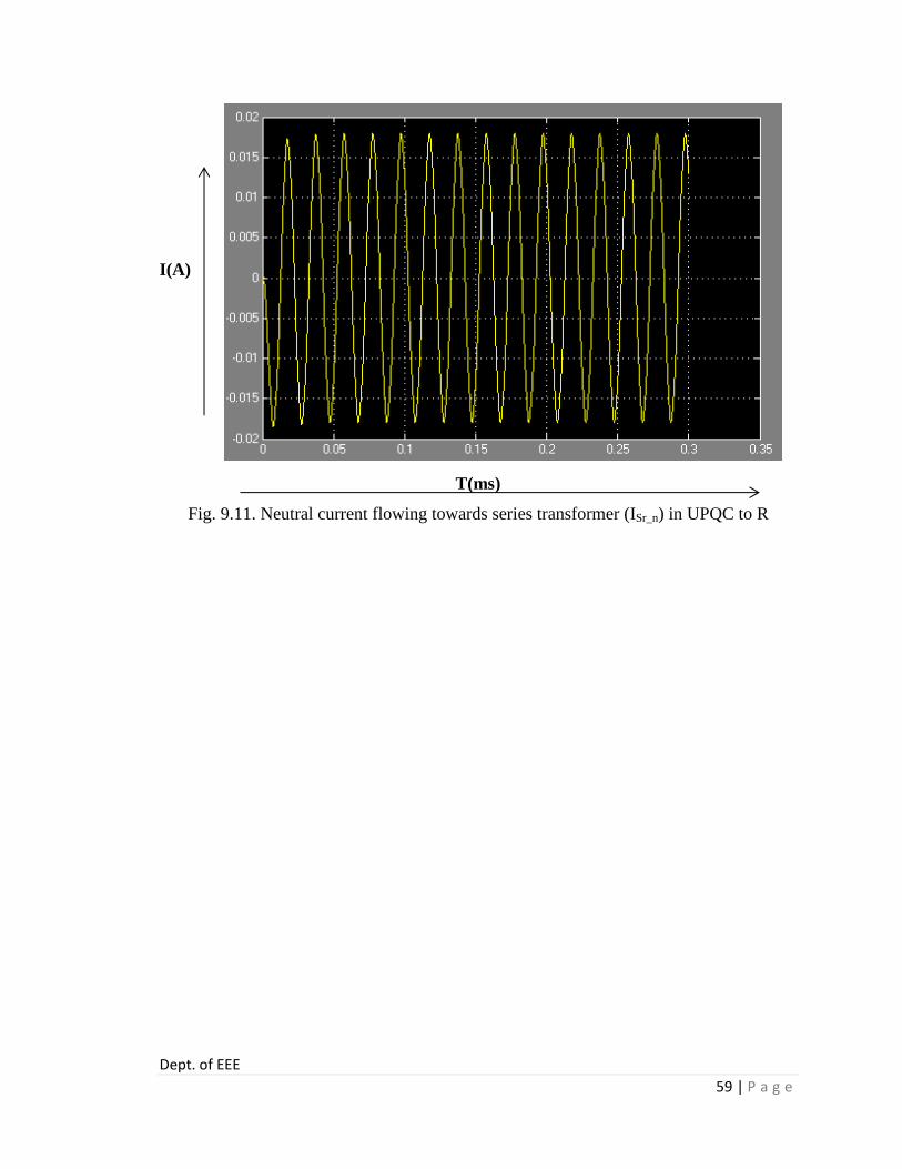
Dept. of EEE
59 | P a g e
I(A)
T(ms)
Fig. 9.11. Neutral current flowing towards series transformer (ISr_n) in UPQC to R

Dept. of EEE
60 | P a g e
9.2 UPQC to RL Load
Fig. 9.12. MATLAB model of UPQC for RL Load
V(v)
T(ms)
Fig. 9.13. Utility Voltage (VS_abc) in UPQC to RL Load

Dept. of EEE
61 | P a g e
V(v)
T(ms)
Fig. 9.14. Load voltage (VL_abc) in UPQC to RL Load
V(v)
T(ms)
Fig. 9.15. Injected Voltage (Vinj_abc) in UPQC to RL Load

Dept. of EEE
62 | P a g e
V(v)
T(ms)
Fig. 9.16. DC-link Voltage (Vdc) in UPQC to RL Load
I(A)
T(ms)
Fig. 9.17. Load Current (IL_abc) in UPQC to RL Load

Dept. of EEE
63 | P a g e
I(A)
T(ms)
Fig. 9.18. Source Current (IS_abc) in UPQC to RL Load
I(A)
T(ms)
Fig. 9.19. Shunt Compensating Current (ISh_abc) in UPQC to RL Load

Dept. of EEE
64 | P a g e
I(A)
T(ms)
Fig. 9.20. Current flowing through load neutral wire (IL_n) in UPQC to RL Load
I(A)
T(ms)
Fig. 9.21. Shunt neutral compensating current (ISh_n) in UPQC to RL Load

Dept. of EEE
65 | P a g e
I(A)
T(ms)
Fig. 9.22. Neutral current flowing towards series transformer (ISr_n) in UPQC to RL Load

Dept. of EEE
66 | P a g e
9.3 UPQC to RLC Load
Fig. 9.23. MATLAB model of UPQC for RLC Load
V(v)
T(ms)
Fig. 9.24. Utility Voltage (VS_abc) in UPQC to RLC Loa

Dept. of EEE
67 | P a g e
V(v)
T(ms)
Fig. 9.25. Load voltage (VL_abc) in UPQC to RLC Load
V(v)
T(ms)
Fig. 9.26. Injected Voltage (Vinj_abc) in UPQC to RLC Load

Dept. of EEE
68 | P a g e
V(v)
T(ms)
Fig. 9.27. DC-link Voltage (Vdc) in UPQC to RLC Load
I(A)
T(ms)
Fig. 9.28. Load Current (IL_abc) in UPQC to RLC Load

Dept. of EEE
69 | P a g e
I(A)
T(ms)
Fig. 9.29. Source Current (IS_abc) in UPQC to RLC Load
I(A)
T(ms)
Fig. 9.30. Shunt Compensating Current (ISh_abc) in UPQC to RLC Load

Dept. of EEE
70 | P a g e
I(A)
T(ms)
Fig. 9.31. Current flowing through load neutral wire (IL_n) in UPQC to RLC Load
I(A)
T(ms)
Fig. 9.32. Shunt neutral compensating current (ISh_n) in UPQC to RLC Load

Dept. of EEE
71 | P a g e
I(A)
T(ms)
Fig. 9.33. Neutral current flowing towards series transformer (ISr_n) in UPQC to RLC
Load

Dept. of EEE
72 | P a g e
9.4 UPQC TO IM LOAD
Fig. 9.34. MATLAB model of UPQC for IM Load
V(v)
T(ms)
Fig. 9.35. Utility Voltage (VS_abc) in UPQC TO IM Load
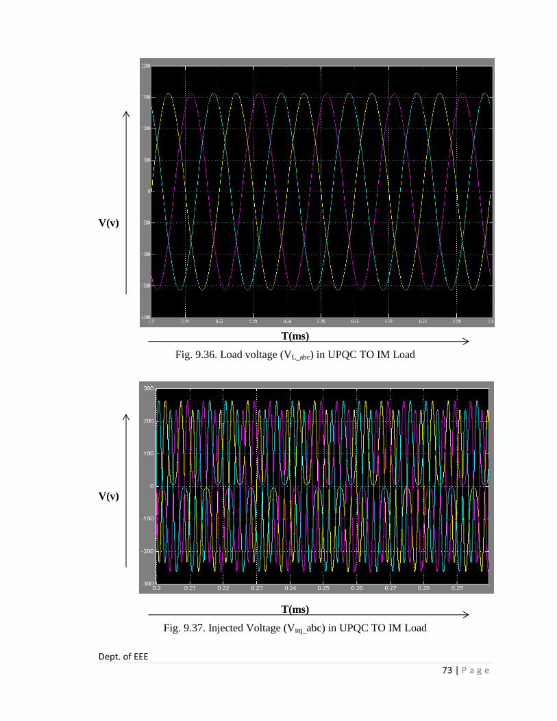
Dept. of EEE
73 | P a g e
V(v)
T(ms)
Fig. 9.36. Load voltage (VL_abc) in UPQC TO IM Load
V(v)
T(ms)
Fig. 9.37. Injected Voltage (Vinj_abc) in UPQC TO IM Load
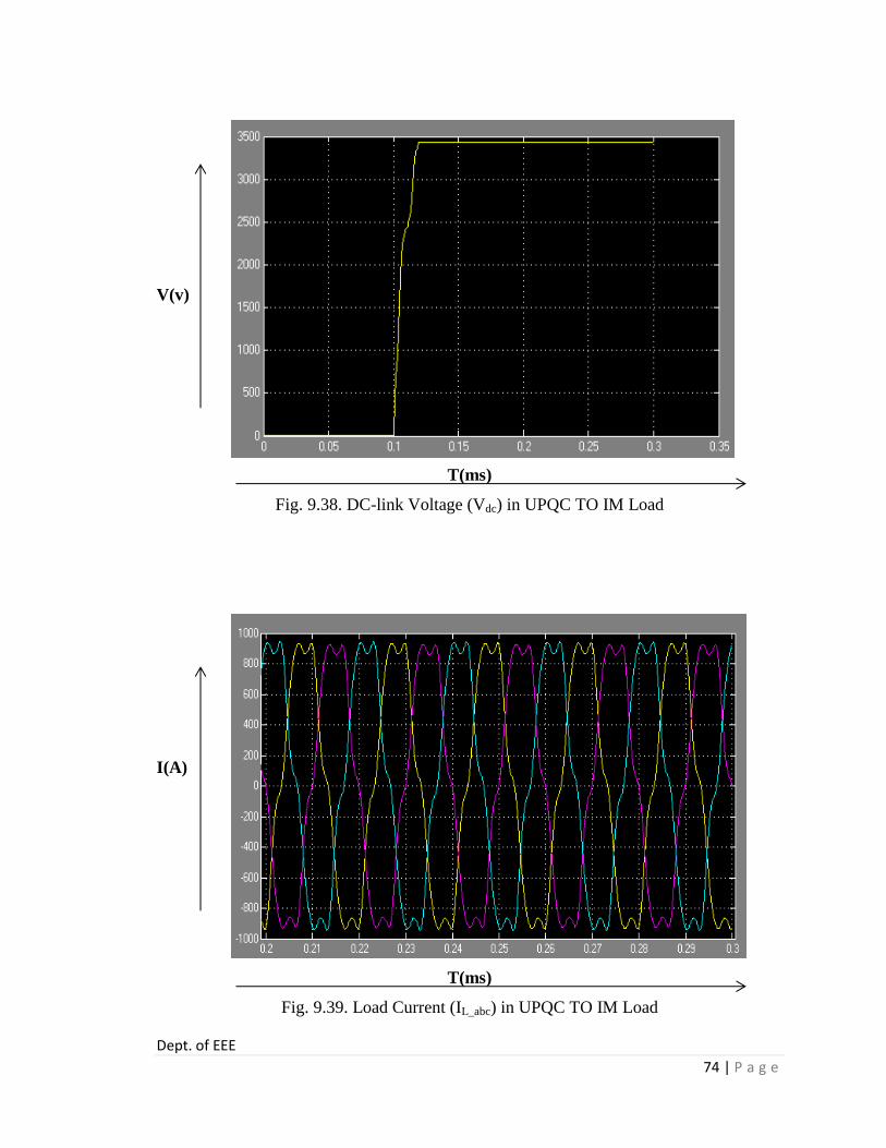
Dept. of EEE
74 | P a g e
V(v)
T(ms)
Fig. 9.38. DC-link Voltage (Vdc) in UPQC TO IM Load
I(A)
T(ms)
Fig. 9.39. Load Current (IL_abc) in UPQC TO IM Load

Dept. of EEE
75 | P a g e
I(A)
T(ms)
Fig. 9.40. Source Current (IS_abc) in UPQC TO IM Load
I(A)
T(ms)
Fig. 9.41. Shunt Compensating Current (ISh_abc) in UPQC TO IM Load
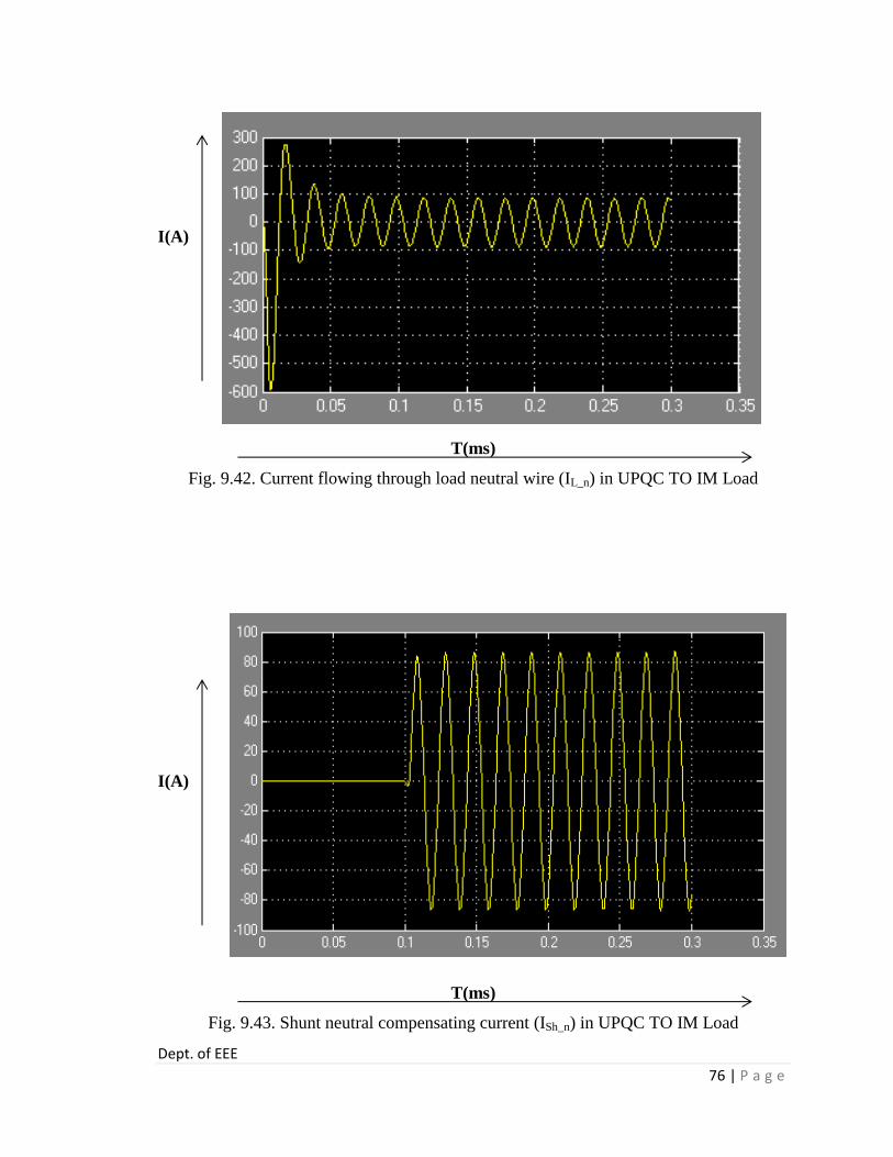
Dept. of EEE
76 | P a g e
I(A)
T(ms)
Fig. 9.42. Current flowing through load neutral wire (IL_n) in UPQC TO IM Load
I(A)
T(ms)
Fig. 9.43. Shunt neutral compensating current (ISh_n) in UPQC TO IM Load

Dept. of EEE
77 | P a g e
I(A)
T(ms)
Fig. 9.44. Neutral current flowing towards series transformer (ISr_n) in UPQC TO IM
Load

Chapter 10
Conclusion

Dept. of EEE
79 | P a g e
10. Conclusion and Future Scope
10.1 Conclusion A new 3P4W topology for distribution system utilizing UPQC has been proposed
in this paper. This proposed topology would be very useful to expand the existing 3P3W
system to 3P4W system where UPQC is installed to compensate the different power
quality problems, which may play an important role in future UPQC-based distribution
system. A new control strategy to generate the balanced reference source current under
unbalanced load condition is also presented in this paper. The MATLAB/Simulink-based
simulation results show that the distorted and unbalanced load currents seen from the
utility side act as perfectly balanced source currents and are free from distortion. The
neutral current that may flow toward the transformer neutral point is effectively
compensated such that the transformer neutral point is always at virtual zero potential.
10.2 Future Scope
In high power applications, the filtering task cannot be performed for the whole
spectrum of harmonics by using a single converter due to the limitations on switching
frequency and power rating of the semiconductor devices. Therefore, compensating the
reactive harmonic components to improve the power quality of the DG integrated system
as well as to avoid the large capacity centralized APF, parallel operation of multiple low
power APF units are increasing. Like APF, UPQC can also be placed at the PCC or at a
high voltage distribution line as a part of DG integrated network or in micro-grid system
to work both in interconnected or islanded mode. At this place, capacity enhancement is
achieved by using Multi-level topologies to reach the higher power levels.
These options are as follows:
i. Multi-level converter based UPQC
ii. Multi-module converter based UPQC
iii. Multi-module (power cell) unit based UPQC
A multi-level converter is proposed to increase the converter operation voltage,
avoiding the series connection of switching elements. However, the multilevel converter

Dept. of EEE
80 | P a g e
is complex to form the output voltage and requires an excessive number of back-
connection diodes or flying capacitors or cascade converters.
A multi-module H-bridge UPQC can also be connected to the distribution system
without series injection transformers. It has the flexibility in expanding the operation
voltage by increasing the number of H-bridge modules isolated through a single-phase
multi winding transformer.
These Multi-module techniques allow the symmetrical distribution of the load
power among the components of the topology, but the classical design procedure must be
modified or refined to ensure the power cell components should be within its maximum
ratings. Therefore, a new design procedure of UPQC with a feature of extending capacity
based on a modular approach is presented.
It is found that research in recent years has placed more emphasis on CPDs,
especially on UPQC, and its application in DG or micro-grid system. Capacity
enhancement has been achieved using multi-level or multi-module and central control
mode, however, the flexibility of UPQC to increase its capacity in future and to cope up
with the increase load demand in low voltage distribution level has not been achieved.

References

Dept. of EEE
82 | P a g e
References
[1] Khadkikar, V. and Chandra, A., “A Novel Structure for Three-Phase Four-Wire
Distribution System Utilizing Unified Power Quality Conditioner (UPQC),” IEEE Trans.
Ind. Appl., vol. 45, no. 5, pp. 1897–1902,3 Sept/Oct. 2009.
[2] B. Singh, K. Al-Haddad, and A. Chandra, “A review of active power filters for power
quality improvement,” IEEE Trans. Ind. Electron., vol. 45, no. 5, pp. 960–971, Oct. 1999.
[3] C. A. Quinn and N. Mohan, “Active filtering of harmonic currents in three phase,
four-wire systems with three-phase and single-phase nonlinear loads,” in Proc. 7th IEEE
APEC, 1992, pp. 829–836.
[4] H. Akagi, Y. Kanazawa, and A. Nabae, “Instantaneous reactive power compensators
comprising switching devices without energy storage components,” IEEE Trans. Ind.
Appl., vol. IA-20, no. 3, pp. 625–630, May/Jun. 1984.
[5] Y. Komatsu and T. Kawabata, “A control method of active power filter in
unsymmetrical and distorted voltage system,” in Proc. Conf. IEEE Power Convers., 1997,
vol. 1, pp. 161–168.
[6] M. T. Haque, “Single-phase PQ theory,” in Proc. 33rd IEEE PESC, 2002, vol. 4, pp.
1815–1820.
[7] J. M. Correa, S. Chakraborty, M. G. Simoes, and F. A. Farret, “A single phase high
frequency AC microgrid with an unified power quality conditioner,” in Conf. Rec. 38th
IEEE IAS Annu. Meeting, 2003, vol. 2, pp. 956–962.
[8] V. Khadkikar, A. Chandra, A. O. Barry, and T. D. Nguyen, “Application of UPQC to
protect a sensitive load on a polluted distribution network,” in Proc. IEEE PES General
Meeting, Montreal, QC, Canada, 2006, 6 pp.
[9] V. Khadkikar, A. Chandra, A. O. Barry, and T. D. Nguyen, “Conceptual analysis of
unified power quality conditioner (UPQC),” in Proc. IEEE ISIE, 2006, pp. 1088–1093.
[10] M. Aredes, K. Heumann, and E. H.Watanabe, “An universal active power line
conditioner,” IEEE Trans. Power Del., vol. 13, no. 2, pp. 545–551, Apr. 1998.
[11] R. Faranda and I. Valade, “UPQC compensation strategy and design aimed at
reducing losses,” in Proc. IEEE ISIE, 2002, vol. 4, pp. 1264–1270.
[12] Roger C. Dugan, Mark F. McGranaghan, Surya Santoso and H. Wayne Beaty,
“Electrical Power Systems Quality,” 3rd
edition, Publisher: The McGraw Hill Compaies.