A Novel Soft-Switching Converter for Switched Reluctance ... · A Novel Soft-Switching Converter...
11
A Novel Soft-Switching Converter for Switched Reluctance Motor Drives KUEI-HSIANG CHAO Department of Electrical Engineering National Chin-Yi University of Technology 35, Lane 215, Sec. 1, Chung-Shan Road, Taiping, Taichung TAIWAN, R.O.C. [email protected] Abstract: - A high efficiency converter for switched reluctance motor (SRM) drive is developed in this paper. In the proposed converter, the power semiconductor device with shorter switching time is employed to implement its high-speed PWM switches. And the soft-switching control is employed for further reducing their switching losses. To achieve this, an auxiliary resonant circuit is added to the PWM switch, and its zero-voltage-transition (ZVT) soft switching is obtained by applying suitable switching signals to the main and auxiliary switches. No extra voltage and/or current sensors are required. Having derived the governing circuit equations, a design procedure is proposed to systematically find the constituted components of the auxiliary branch. As to the low-speed commutation switches, they are realized using the power device having low on-state voltage. Owing to the ability of making PWM switching control, the SRM motor drive with the proposed converter possesses good driving performance. The performance of the designed converter is demonstrated by some simulation and experimental results. An approach for measuring the energy conversion efficiency of a SRM drive is also proposed. Key-Words: Switched reluctance motor (SRM), Soft-switching converter, Zero voltage transition (ZVT), PWM, Efficiency measurement, High-efficiency converter. 1 Introduction Switched reluctance motor (SRM) possesses many advantages, such as rigid mechanical structure, brushless operation, higher conversion efficiency and power density [1]. Moreover, its converter circuit is simple and free from shoot-through fault [1-4]. However, in addition to the generation of large acoustic noise and large torque ripple, its developed torque characteristic is quite nonlinear. These factors may limit the capability of a SRM in high-performance applications. During the past decades, many researches have been done to improve the performance of a SRM drive. These include: motor design [2], converter circuit [3,4], voltage boosting circuit [5,6], current waveform programming [7,8], commutation tuning [9]. And other related issues, such as noise reduction, equivalent circuit development, current and speed controls, sensorless control, digital simulation, etc. As generally recognized, the driving performance of a SRM motor drive is significantly affected by its employed converter and switching control. The whole motor drive performance is also affected by the converter efficiency, particularly for the battery-powered motor drive system. The conventional hard-switched converters possess inherent disadvantages of generating large switching losses, switching stresses and electromagnetic magnetic interference (EMI). These problems can be effectively reduced employing soft-switching technique to let the switches have zero voltage and/or zero current switchings. Soft-switching converters can be broadly categorized into resonant converters and zero voltage (current) (ZV(C)T) transition converters. The former types of converters possess larger limitations in circuit configuration and PWM switching control. As to the latter, the circuits can be formed from the conventional ones by adding simple auxiliary resonant branch. And the soft switching can be obtained by applying suitable switching signals to the main and auxiliary switches. Recently, there have been some soft-switching converters being specifically developed for powering SRMs. For the three-phase SRM soft-switching converter developed in [10], an auxiliary branch consisting of a LC resonant circuit and an auxiliary switch is used to let the main switches have ZVS at turn off. The converter presented in [11] is basically an improved circuit configuration of the one in [10]. In which, the auxiliary switch is not necessary. However, these types of converters suffer from the limitations: (i) the PWM switching control can not be performed; and (ii) the switching frequency of converter is limited, since it must be synchronized to WSEAS TRANSACTIONS on CIRCUITS and SYSTEMS Kuei-Hsiang Chao ISSN: 1109-2734 411 Issue 5, Volume 8, May 2009
-
Upload
nguyenminh -
Category
Documents
-
view
234 -
download
3
Transcript of A Novel Soft-Switching Converter for Switched Reluctance ... · A Novel Soft-Switching Converter...
A Novel Soft-Switching Converter for Switched Reluctance Motor Drives
KUEI-HSIANG CHAO Department of Electrical Engineering
National Chin-Yi University of Technology 35, Lane 215, Sec. 1, Chung-Shan Road, Taiping, Taichung
TAIWAN, R.O.C. [email protected]
Abstract: - A high efficiency converter for switched reluctance motor (SRM) drive is developed in this paper. In the proposed converter, the power semiconductor device with shorter switching time is employed to implement its high-speed PWM switches. And the soft-switching control is employed for further reducing their switching losses. To achieve this, an auxiliary resonant circuit is added to the PWM switch, and its zero-voltage-transition (ZVT) soft switching is obtained by applying suitable switching signals to the main and auxiliary switches. No extra voltage and/or current sensors are required. Having derived the governing circuit equations, a design procedure is proposed to systematically find the constituted components of the auxiliary branch. As to the low-speed commutation switches, they are realized using the power device having low on-state voltage. Owing to the ability of making PWM switching control, the SRM motor drive with the proposed converter possesses good driving performance. The performance of the designed converter is demonstrated by some simulation and experimental results. An approach for measuring the energy conversion efficiency of a SRM drive is also proposed. Key-Words: Switched reluctance motor (SRM), Soft-switching converter, Zero voltage transition (ZVT), PWM,
Efficiency measurement, High-efficiency converter. 1 Introduction Switched reluctance motor (SRM) possesses many advantages, such as rigid mechanical structure, brushless operation, higher conversion efficiency and power density [1]. Moreover, its converter circuit is simple and free from shoot-through fault [1-4]. However, in addition to the generation of large acoustic noise and large torque ripple, its developed torque characteristic is quite nonlinear. These factors may limit the capability of a SRM in high-performance applications. During the past decades, many researches have been done to improve the performance of a SRM drive. These include: motor design [2], converter circuit [3,4], voltage boosting circuit [5,6], current waveform programming [7,8], commutation tuning [9]. And other related issues, such as noise reduction, equivalent circuit development, current and speed controls, sensorless control, digital simulation, etc.
As generally recognized, the driving performance of a SRM motor drive is significantly affected by its employed converter and switching control. The whole motor drive performance is also affected by the converter efficiency, particularly for the battery-powered motor drive system. The conventional hard-switched converters possess inherent disadvantages of generating large switching
losses, switching stresses and electromagnetic magnetic interference (EMI). These problems can be effectively reduced employing soft-switching technique to let the switches have zero voltage and/or zero current switchings. Soft-switching converters can be broadly categorized into resonant converters and zero voltage (current) (ZV(C)T) transition converters. The former types of converters possess larger limitations in circuit configuration and PWM switching control. As to the latter, the circuits can be formed from the conventional ones by adding simple auxiliary resonant branch. And the soft switching can be obtained by applying suitable switching signals to the main and auxiliary switches.
Recently, there have been some soft-switching converters being specifically developed for powering SRMs. For the three-phase SRM soft-switching converter developed in [10], an auxiliary branch consisting of a LC resonant circuit and an auxiliary switch is used to let the main switches have ZVS at turn off. The converter presented in [11] is basically an improved circuit configuration of the one in [10]. In which, the auxiliary switch is not necessary. However, these types of converters suffer from the limitations: (i) the PWM switching control can not be performed; and (ii) the switching frequency of converter is limited, since it must be synchronized to
WSEAS TRANSACTIONS on CIRCUITS and SYSTEMS Kuei-Hsiang Chao
ISSN: 1109-2734 411 Issue 5, Volume 8, May 2009
the resonant frequency of auxiliary branch. In [12], a current-controlled quasi-resonant unipolar converter using thyristors for SRM is presented. Obviously, the PWM current control performance is also limited. Another group of soft-switching converters [13,14] developed for SRM belong to resonant DC link converters. The one in [14] has limited switch voltage stress through using the actively clamped resonant DC link. These converters also lack of PWM switching control capability. In [15], the ZVT switching technique [16,17] is applied to let the switches in a Miller converter possess ZVS soft-switching characteristics. However, only simulation results are presented.
In this paper, a converter with high efficiency for SRM is designed and implemented. First, a SRM drive powered using hard-switched modified Miller converter is established. Then the proposed converter is introduced. It is formed from the conventional Miller’s converter via suitable modifications in circuit and switching control. Each PWM switch is augmented by an auxiliary branch, and the ZVT soft switching is achieved by applying suitable switching signals to the PWM main and auxiliary switches. No additional sensors are required for making the soft-switching control. Having analyzed and derived the governing equations of the converter in various modes, the quantitative design for the auxiliary branch is made. As to the commutation switches, they are implemented using power devices with lower on-state voltage. In making the performance evaluation of the developed converter, an efficiency measurement approach is introduced. The simulation and experimental results show that higher energy conversion efficiency of the SRM drive with the designed converter is obtained, and the driving control performance remains unchanged.
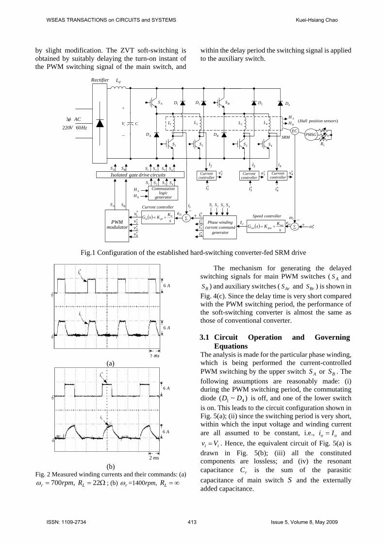
2 Establishment of the SRM Drive Fig. 1 shows the established SRM drive powered by the hard-switched 2(n+1)(n is the phase number of motor) Miller converter, which uses two PWM switches to lessen their power burden. The SRM, which is manufactured by TASC Drives Ltd., is rated as 8/6 4-phase, 1500rpm, 4kW. The DC-link voltage is set as Vi=310V. The permanent magnet synchronous generator (PMSG) equipped with switched resistance is served as the dynamic load of the motor. For the converter, the four lower switches are used for making exciting commutation of armature phase windings. Their switching frequency is low, and the choice of power switch is emphasized in having low on-state voltage. The MOS-controlled thyristor (MCT) may be a better choice. However, it
is not popularly available commercially. Thus the IGBT IXGH41N60 (600V/75A, 0.45 sμ , 1.6V/41A) manufactured by IXYS Company is adopted for implementing these commutation switches. As to the upper two switches, since they are in charge of PWM switching control, the power switch with shorter switching time is preferable for reducing the switching losses. Thus the IGBT IXGH39N60BD1 (600V/75A, sμ2.0 , 1.8V/39A) is adopted here. And moreover, the ZVT soft-switching control will be employed for further reducing their switching losses. The control system shown in Fig. 1 is cascade-configured consisting of speed and current loops. And the current-controlled PWM scheme is employed to obtain good winding current tracking waveform. The commutation signals ( 1S 4~ S ) for lower switches are yielded from the quadrature Hall sensing signals AH and BH . For ease of implementation, both the speed and current controllers are chosen to be the PI types:
,1.15.0)(s
sGc +=ω ssGci
710510)( += (1)
Having established the motor drive, some measured results are provided to show its correctness and performance. Figs. 2(a) and 2(b) show the measured winding currents and their commands of phase 1 at
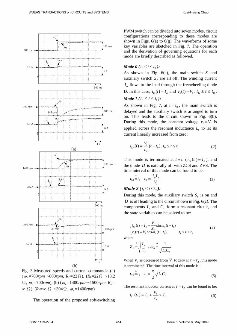
,700( rpmr =ω )22Ω=LR and ,1400( rpmr =ω Ω∞=LR ), respectively. Fig. 3(a) shows the rotor
speed responses and current commands due to step command change (700rpm→800rpm, RL=22Ω) and step load resistance change (RL=22Ω→ 13.2Ω ,
rpmr 700=ω ). Fig. 3(b) shows the results corresponding to ),15001400( Ω∞=→ LRrpmrpm and ,304( Ω→Ω∞=LR rpmr 1400=ω ). The results shown in Figs. 2 and 3 indicate that the established SRM drive can normally be operated and possess satisfactory performances in winding current tracking waveform and speed dynamic responses. 3 The Proposed Converter for SRM
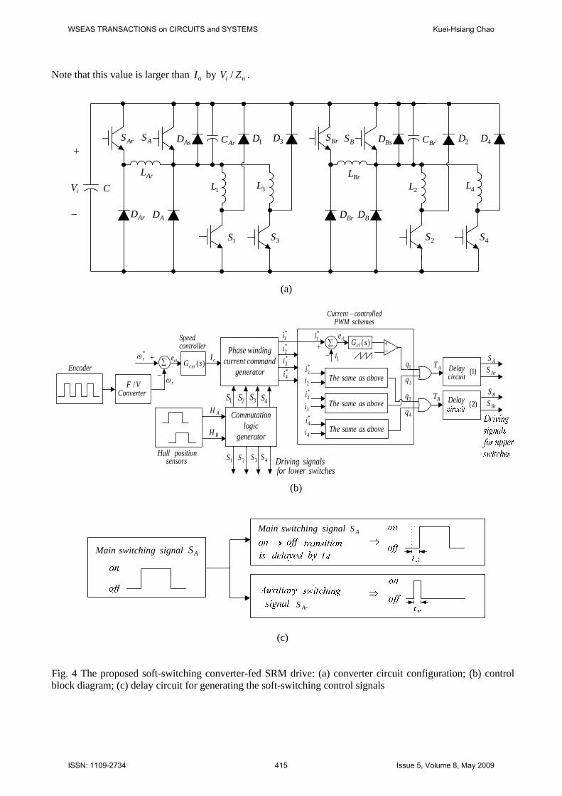
Drive Circuit configuration of the proposed soft-switching converter is drawn in Fig. 4(a), which is formed from the modified Miller’s converter shown in Fig. 1 by augmenting an auxiliary resonant branch circuit for each PWM switch to reduce its switching losses. Each auxiliary branch consists of a switch, a diode and a LC resonant circuit. The control system block diagram of the proposed soft-switching converter is shown in Fig. 4(b), which is obtained from Fig. 1(b)
WSEAS TRANSACTIONS on CIRCUITS and SYSTEMS Kuei-Hsiang Chao
ISSN: 1109-2734 412 Issue 5, Volume 8, May 2009
by slight modification. The ZVT soft-switching is obtained by suitably delaying the turn-on instant of the PWM switching signal of the main switch, and
within the delay period the switching signal is applied to the auxiliary switch.
EC
LR
PMSG
∑ ∗rω+
−controllerSpeed
rωcI
generatorcommandcurrentwindingPhase
1S 2S 3S 4S
*1i*2i*3i*4i
+∑
generatorlogic
nCommutatio
−1icontrollerCurrent
circuitsdrivegateIsolated
*2v*3v*4v
AH
BH
2i 3i 4i*2v
controllerCurrent
*4i
*4v
SRM
AH
BH )( sensorspositionHall1L 3L 2L 4L
1D 3D 2D
AD
AS
4S2S3S1S
BD
BS4D
ωe
1ie
2S 3S 4S1S
modulatorPWM
*3i
*3v
controllerCurrent
controllerCurrent
( )s
KKsG ipc
ωωω +=
( )s
KKsG iipici +=
*2i
ACφ3
HzV 60220
dLRectifier
iV
+
−
C
AS BS
*1v
2S 3S 4S1SAS BS
Fig.1 Configuration of the established hard-switching converter-fed SRM drive
A6
A6
*1i
1i
(a)
ms2
A6
A6
*1i
1i
(b)
Fig. 2 Measured winding currents and their commands: (a) ,700rpmr =ω Ω= 22LR ; (b) rω =1400rpm, ∞=LR
The mechanism for generating the delayed switching signals for main PWM switches ( AS and
BS ) and auxiliary switches ( ArS and BrS ) is shown in Fig. 4(c). Since the delay time is very short compared with the PWM switching period, the performance of the soft-switching converter is almost the same as those of conventional converter. 3.1 Circuit Operation and Governing
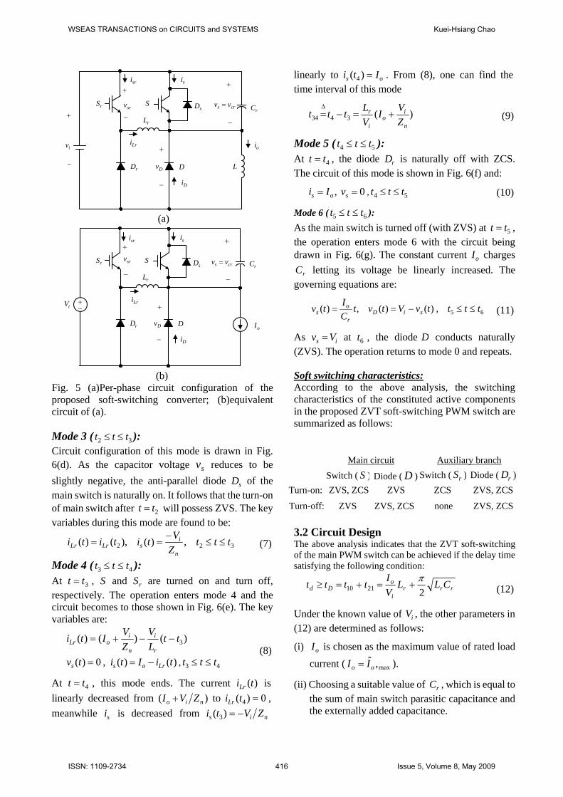
Equations The analysis is made for the particular phase winding, which is being performed the current-controlled PWM switching by the upper switch AS or BS . The following assumptions are reasonably made: (i) during the PWM switching period, the commutating diode )~( 41 DD is off, and one of the lower switch is on. This leads to the circuit configuration shown in Fig. 5(a); (ii) since the switching period is very short, within which the input voltage and winding current are all assumed to be constant, i.e., oo Ii = and
ii Vv = . Hence, the equivalent circuit of Fig. 5(a) is drawn in Fig. 5(b); (iii) all the constituted components are lossless; and (iv) the resonant capacitance rC is the sum of the parasitic capacitance of main switch S and the externally added capacitance.
WSEAS TRANSACTIONS on CIRCUITS and SYSTEMS Kuei-Hsiang Chao
ISSN: 1109-2734 413 Issue 5, Volume 8, May 2009
ms500
A6
rpm100
*rω
cI
rωrpm700
A5.5
A7
s1
rpm100
rω
A6
rpm145
rpm700
A7.5
cI
(a)
ms500
A6
rpm100
*rω
cI
rωrpm1400
A5.4
A9.5
s1
rpm100
rω
A6
rpm28rpm1400
A2.4
cI
(b)
Fig. 3 Measured speeds and current commands: (a) ( rω =700rpm→800rpm, RL=22Ω), (RL=22Ω→13.2Ω, rω =700rpm); (b) ( rω =1400rpm→1500rpm, RL= ∞Ω), (RL=∞Ω→304Ω, rω =1400rpm)
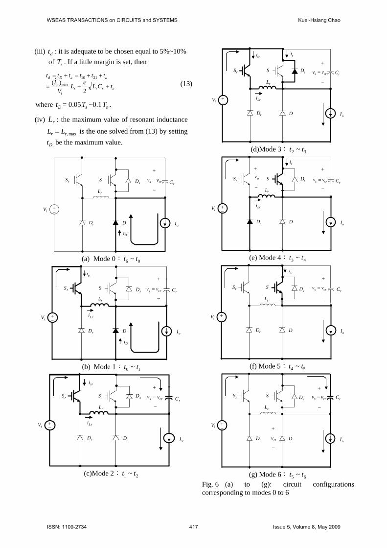
The operation of the proposed soft-switching
PWM switch can be divided into seven modes, circuit configurations corresponding to these modes are shown in Figs. 6(a) to 6(g). The waveforms of some key variables are sketched in Fig. 7. The operation and the derivation of governing equations for each mode are briefly described as followed. Mode 0 ( 06 ttt ≤≤ ): As shown in Fig. 6(a), the main switch S and auxiliary switch rS are all off. The winding current
oI flows to the load through the freewheeling diode D. In this case, oD Iti =)( and is Vtv =)( , 06 ttt ≤≤ . Mode 1 ( 10 ttt ≤≤ ): As shown in Fig. 7, at 0tt = , the main switch is delayed and the auxiliary switch is arranged to turn on. This leads to the circuit shown in Fig. 6(b). During this mode, the constant voltage ii Vv = is applied across the resonant inductance rL to let its current linearly increased from zero:
)()( 0ttLVti
r
iLr −= , 10 ttt ≤≤ (2)
This mode is terminated at 1tt = ( oLr Iti =)( 1 ), and the diode D is naturally off with ZCS and ZVS. The time interval of this mode can be found to be:
i
ro
VLIttt =−=
Δ
0110 (3)
Mode 2 ( 21 ttt ≤≤ ): During this mode, the auxiliary switch rS is on and D is off leading to the circuit shown in Fig. 6(c). The components rL and rC form a resonant circuit, and the state variables can be solved to be:
⎪⎩
⎪⎨⎧
≤≤−=
−+=
211
1
),(cos)(
)(sin)(
tttttVtv
ttZVIti
nis
nn
ioLr
ω
ω (4)
where
r
rn C
LZΔ= ,
rrn CL
1Δ=ω
When sv is decreased from iV to zero at 2tt = , this mode is terminated. The time interval of this mode is:
rrCLttt21221π
=−=Δ
(5)
The resonant inductor current at 2tt = can be found to be:
on
ioLr I
ZVIti >+=)( 2 (6)
WSEAS TRANSACTIONS on CIRCUITS and SYSTEMS Kuei-Hsiang Chao
ISSN: 1109-2734 414 Issue 5, Volume 8, May 2009
Note that this value is larger than oI by ni ZV / .
+
−
1L 3L 2L 4L
3D
4S2S3S1S
ArS
ArL
ArD AD
AS 1DArCAsD
BrD BD
BrL
BrS BS BsD BrC 4D2D
iV C
(a)
rω
*rω
∑ )(sGcω
controllerSpeed
generatorcommandcurrentwindingPhase
+
−VF /
Converter
*1i*2i*3i*4i
switcheslowerforsignalsDriving
cIωe
generatorlogic
nCommutatio
1S 2S 3S 4S
AH
BH
positionHallsensors
1S 2S 3S 4S
EncoderaboveassameThe
*1i
1i+
−
1ie+−
)(sGci
aboveassameThe
2i
*2i
3i
*3i
4i
∑
1q
3q
2q
4q
schemesPWMcontrolledCurrent −
*4i
BT
Delaycircuit
ASArSAT
DelayBSBrS
aboveassameThe
)1(
)2(
(b)
signalswitchingMain
signalswitchingMain
AS
AS
ArS
(c)
Fig. 4 The proposed soft-switching converter-fed SRM drive: (a) converter circuit configuration; (b) control block diagram; (c) delay circuit for generating the soft-switching control signals
WSEAS TRANSACTIONS on CIRCUITS and SYSTEMS Kuei-Hsiang Chao
ISSN: 1109-2734 415 Issue 5, Volume 8, May 2009
rS
rL
rD D
SsD
rC+
−
iv
L
−
+sisri
Lrioi
Dv
−
+
srv−
+
crs vv =
Di
(a)
rS
rL
rD D
SsD
iV
oI
+−
rCcrs vv =
−
+sisri
Lri
Dv
−
+
srv
−
+
Di
(b)
Fig. 5 (a)Per-phase circuit configuration of the proposed soft-switching converter; (b)equivalent circuit of (a). Mode 3 ( 32 ttt ≤≤ ): Circuit configuration of this mode is drawn in Fig. 6(d). As the capacitor voltage sv reduces to be slightly negative, the anti-parallel diode sD of the main switch is naturally on. It follows that the turn-on of main switch after 2tt = will possess ZVS. The key variables during this mode are found to be:
322 ,)(),()( tttZVtititin
isLrLr ≤≤
−== (7)
Mode 4 ( 43 ttt ≤≤ ): At 3tt = , S and rS are turned on and turn off, respectively. The operation enters mode 4 and the circuit becomes to those shown in Fig. 6(e). The key variables are:
)()()( 3ttLV
ZVIti
r
i
n
ioLr −−+=
)()(,0)( tiItitv Lross −== , 43 ttt ≤≤ (8)
At 4tt = , this mode ends. The current )(tiLr is linearly decreased from )( nio ZVI + to 0)( 4 =tiLr , meanwhile si is decreased from nis ZVti −=)( 3
linearly to os Iti =)( 4 . From (8), one can find the time interval of this mode
)(3434n
io
i
r
ZVI
VLttt +=−=
Δ (9)
Mode 5 ( 54 ttt ≤≤ ): At 4tt = , the diode rD is naturally off with ZCS. The circuit of this mode is shown in Fig. 6(f) and:
0, == sos vIi , 54 ttt ≤≤ (10)
Mode 6 ( 65 ttt ≤≤ ): As the main switch is turned off (with ZVS) at 5tt = , the operation enters mode 6 with the circuit being drawn in Fig. 6(g). The constant current oI charges
rC letting its voltage be linearly increased. The governing equations are:
65,)()(,)( ttttvVtvtCItv siD
r
os ≤≤−== (11)
As is Vv = at 6t , the diode D conducts naturally (ZVS). The operation returns to mode 0 and repeats. Soft switching characteristics: According to the above analysis, the switching characteristics of the constituted active components in the proposed ZVT soft-switching PWM switch are summarized as follows:
Main circuit Auxiliary branch
Switch ( S ) Diode ( D ) Switch ( rS ) Diode ( rD )Turn-on: ZVS, ZCS ZVS ZCS ZVS, ZCS
Turn-off: ZVS ZVS, ZCS none ZVS, ZCS 3.2 Circuit Design The above analysis indicates that the ZVT soft-switching of the main PWM switch can be achieved if the delay time satisfying the following condition:
rrri
oDd CLL
VItttt
22110π
+=+=≥ (12)
Under the known value of iV , the other parameters in (12) are determined as follows:
(i) oI is chosen as the maximum value of rated load current ( max,ˆ
oo II = ).
(ii) Choosing a suitable value of rC , which is equal to the sum of main switch parasitic capacitance and the externally added capacitance.
WSEAS TRANSACTIONS on CIRCUITS and SYSTEMS Kuei-Hsiang Chao
ISSN: 1109-2734 416 Issue 5, Volume 8, May 2009
(iii) dt : it is adequate to be chosen equal to 5%~10% of sT . If a little margin is set, then
ε
εεπ tCLL
VI
tttttt
rrri
o
Dd
++=
++=+=
2)ˆ( max
2110 (13)
where Dt = 0.05 sT ~0.1 sT .
(iv) rL : the maximum value of resonant inductance
max,rr LL = is the one solved from (13) by setting
Dt be the maximum value.
rS
rL
rD D
SsD
iV
oI
+−
rCcrs vv =
−
+
Di
(a) Mode 0: 06 ~ tt
rS
rL
rD D
SsD
iV
oI
Lri+−
rC
sri
crs vv =
−
+
Di
(b) Mode 1: 10 ~ tt
rS
rL
rD D
S sD
iV
oI
Lri
crs vv =
−
+
+−
rC
sri
(c)Mode 2: 21 ~ tt
rS
rL
rD D
S sD
iV
oI
Lri
si
crs vv =
−
+
+−
rC
sri
(d)Mode 3: 32 ~ tt
rS
rL
rD D
S sD
iV
oI
+−
rCcrs vv =
−
+si
Lri
srv
−
+
(e) Mode 4: 43 ~ tt
rS
rL
rD D
SsD
iV
oI
+−
rCcrs vv =
−
+si
(f) Mode 5: 54 ~ tt
rS
rL
rD D
SsD
iV
oI
+−
rCcrs vv =
−
+
Dv
−
+
(g) Mode 6: 65 ~ tt
Fig. 6 (a) to (g): circuit configurations corresponding to modes 0 to 6
WSEAS TRANSACTIONS on CIRCUITS and SYSTEMS Kuei-Hsiang Chao
ISSN: 1109-2734 417 Issue 5, Volume 8, May 2009
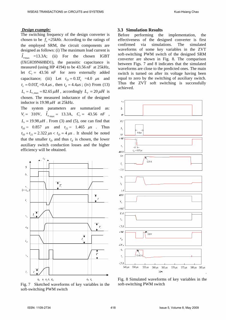
Design example: The switching frequency of the design converter is chosen to be sf =25kHz. According to the ratings of the employed SRM, the circuit components are designed as follows: (i) The maximum load current is
maxoI =13.3A; (ii) For the chosen IGBT (IXGH39N60BD1), the parasitic capacitance is measured (using HP 4194) to be 43.56 nF at 25kHz, let =rC 43.56 nF for zero externally added capacitance; (iii) Let sD Tt 1.0= =4.0 sμ and
sTt 01.0=ε =0.4 sμ , then std μ4.4= ; (iv) From (13) == max,rr LL 82.65 Hμ , accordingly =rL 20 Hμ is
chosen. The measured inductance of the designed inductor is 19.98 Hμ at 25kHz. The system parameters are summarized as:
=iV 310V, =max,oI 13.3A, =rC 43.56 nF ,
=rL 19.98 Hμ . From (3) and (5), one can find that =10t 0.857 sμ and =21t 1.465 sμ . Thus
=+ 2110 tt 2.322 <sμ =Dt 4 sμ . It should be noted that the smaller Dt and thus dt is chosen, the lower auxiliary switch conduction losses and the higher efficiency will be obtained.
)( crv=
Fig. 7 Sketched waveforms of key variables in the soft-switching PWM switch
3.3 Simulation Results Before performing the implementation, the effectiveness of the designed converter is first confirmed via simulations. The simulated waveforms of some key variables in the ZVT soft-switching PWM switch of the designed SRM converter are shown in Fig. 8. The comparison between Figs. 7 and 8 indicates that the simulated waveforms are close to the predicted ones. The main switch is turned on after its voltage having been equal to zero by the switching of auxiliary switch. Thus the ZVT soft switching is successfully achieved.
A 9.12
s545 μ s550 μ s555 μ s560 μ s 565 μ s 570 μ s 575 μ s580 μ s585 μ
stD μ97.0=
sμ4.4
A 42.13
V 103
.
Fig. 8 Simulated waveforms of key variables in the soft-switching PWM switch
WSEAS TRANSACTIONS on CIRCUITS and SYSTEMS Kuei-Hsiang Chao
ISSN: 1109-2734 418 Issue 5, Volume 8, May 2009
4 Implementation and Performance Measurement of the Designed Converter
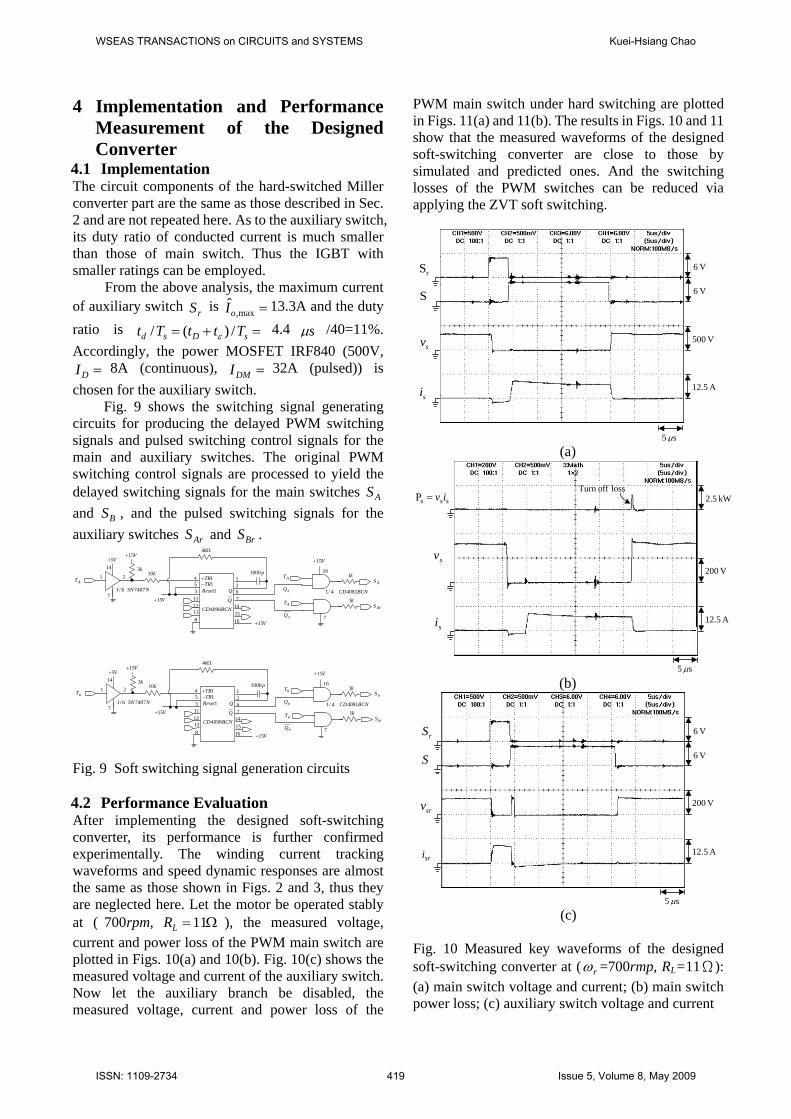
4.1 Implementation The circuit components of the hard-switched Miller converter part are the same as those described in Sec. 2 and are not repeated here. As to the auxiliary switch, its duty ratio of conducted current is much smaller than those of main switch. Thus the IGBT with smaller ratings can be employed.
From the above analysis, the maximum current of auxiliary switch rS is =max,oI 13.3A and the duty ratio is =+= sDsd TttTt /)(/ ε 4.4 sμ /40=11%. Accordingly, the power MOSFET IRF840 (500V,
=DI 8A (continuous), =DMI 32A (pulsed)) is chosen for the auxiliary switch.
Fig. 9 shows the switching signal generating circuits for producing the delayed PWM switching signals and pulsed switching control signals for the main and auxiliary switches. The original PWM switching control signals are processed to yield the delayed switching signals for the main switches AS and BS , and the pulsed switching signals for the auxiliary switches ArS and BrS .
AT 21
14V5+
7NSN74076/1
V15+
k3
V15+
k10
BCNCD4098
453
1112138
621
Ωk4
p1000
147
1615
V15+
Q
Q
1TR+1TR−
R 1eset BCNCD40814/1
ATAS
k1
ATArS
k1
7
V15+
16
AQ
AQ
BT 21
14V5+
7NSN74076/1
V15+
k3
V15+
k10
BCNCD4098
453
1112138
621
Ωk4
p1000
147
1615
V15+
Q
Q
1TR+1TR−
R 1eset BCNCD40814/1
BTBS
k1
BTBrS
k1
7
V15+
16
BQ
BQ
Fig. 9 Soft switching signal generation circuits
4.2 Performance Evaluation After implementing the designed soft-switching converter, its performance is further confirmed experimentally. The winding current tracking waveforms and speed dynamic responses are almost the same as those shown in Figs. 2 and 3, thus they are neglected here. Let the motor be operated stably at ( ,700rpm Ω=11LR ), the measured voltage, current and power loss of the PWM main switch are plotted in Figs. 10(a) and 10(b). Fig. 10(c) shows the measured voltage and current of the auxiliary switch. Now let the auxiliary branch be disabled, the measured voltage, current and power loss of the
PWM main switch under hard switching are plotted in Figs. 11(a) and 11(b). The results in Figs. 10 and 11 show that the measured waveforms of the designed soft-switching converter are close to those by simulated and predicted ones. And the switching losses of the PWM switches can be reduced via applying the ZVT soft switching.
V 6
V 6
V 500
s5 μ
A 12.5
rS
S
sv
si
(a)
s 5 μ
V 200
A 12.5
kW 2.5ssiv=sPloss offTurn
sv
si
(b)
s5 μ
V 200
A 12.5
srv
sri
V 6
V 6
rS
S
(c)
Fig. 10 Measured key waveforms of the designed soft-switching converter at ( rω =700rmp, RL=11Ω): (a) main switch voltage and current; (b) main switch power loss; (c) auxiliary switch voltage and current
WSEAS TRANSACTIONS on CIRCUITS and SYSTEMS Kuei-Hsiang Chao
ISSN: 1109-2734 419 Issue 5, Volume 8, May 2009
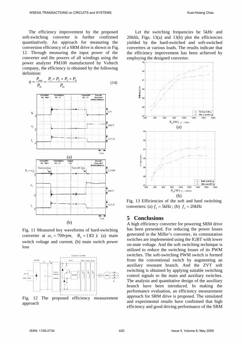
The efficiency improvement by the proposed soft-switching converter is further confirmed quantitatively. An approach for measuring the conversion efficiency of a SRM drive is shown in Fig. 12. Through measuring the input power of the converter and the powers of all windings using the power analyzer PM100 manufactured by Voltech company, the efficiency is obtained by the following definition:
inin
out
PPPPP
PP 4321 +++
==η (14)
V 6
V 500
s5 μ
A 12.5
S
sv
si
(a)
s5 μ
V 200
A 12.5
kW 2.5ssiv=sPloss offTurn
sv
si
losson Turn
(b)
Fig. 11 Measured key waveforms of hard-switching converter at ,700rpmr =ω Ω=11LR ): (a) main switch voltage and current; (b) main switch power loss
dL
CHzV 60220
ACφ3
inP
PM100
analyzerPower
Rectifier
PM100
1P1L
PMSG
LR
EC
1Phase 2Phase 3Phase 4Phase
SRMfed-Converter
iV
+
−
2P 3P 4P
Fig. 12 The proposed efficiency measurement approach
Let the switching frequencies be kHz5 and 20kHz, Figs. 13(a) and 13(b) plot the efficiencies yielded by the hard-switched and soft-switched converters at various loads. The results indicate that the efficiency improvement has been achieved by employing the designed converter.
200 400 600 800 1000 1200 1400 160087
88
89
90
91
92
93
)5( kHzfs = (a)
200 400 600 800 1000 1200 1400 1600 180087
88
89
90
91
92
93
)20( kHzfs = (b)
Fig. 13 Efficiencies of the soft and hard switching converters: (a) kHzfs 5= ; (b) kHzfs 20=
5 Conclusions A high efficiency converter for powering SRM drive has been presented. For reducing the power losses generated in the Miller’s converter, its commutation switches are implemented using the IGBT with lower on-state voltage. And the soft switching technique is utilized to reduce the switching losses of its PWM switches. The soft-switching PWM switch is formed from the conventional switch by augmenting an auxiliary resonant branch. And the ZVT soft switching is obtained by applying suitable switching control signals to the main and auxiliary switches. The analysis and quantitative design of the auxiliary branch have been introduced. In making the performance evaluation, an efficiency measurement approach for SRM drive is proposed. The simulated and experimental results have confirmed that high efficiency and good driving performance of the SRM
)W(Pin
)W(Pin
WSEAS TRANSACTIONS on CIRCUITS and SYSTEMS Kuei-Hsiang Chao
ISSN: 1109-2734 420 Issue 5, Volume 8, May 2009
drive powered by the proposed soft-switching converter are obtained.
References [1] T. J. E. Miller, Switched Reluctance Motors
and their Control, Clarendon Press, Oxford, 1993.
[2] T. J. E. Miller, “Optimal Design of Switched Reluctance Motors,” IEEE Transactions on Industrial Electronics, Vol. 49, No. 1, 2002 , pp. 15-27.
[3] S. Vukosavic and V. R. Stefanovic, “SRM Inverter Topologies: a Comparative Evaluation,” IEEE Transactions on Industry Applications, Vol. 27, No. 6, 1991, pp. 1034-1049.
[4] C. Pollock and M. Barnes, “Power Electronic Converters for Switched Reluctance Drives,” IEEE Transactions on Power Electronics, Vol. 13, No. 6, Nov. 1998, pp. 1100-1111.
[5] Y. G. Dessouky, B. W. Williams and J. E. Fletcher, “A Novel Power Converter with Voltage-Boosting Capacitors for a Four-Phase SRM Drive,” IEEE Transactions on Industry Applications, Vol. 45, No. 5, 1998, pp. 815-823.
[6] K. I. Hwu and C. M. Liaw, “DC-link Voltage Boosting and Switching Control for Switched Reluctance Motor Drives,” IEE Proceedings-Electric Power Applications, Vol. 147, No. 5, 2000, pp. 337-344.
[7] I. Husain and M. Ehsani, “Torque Ripple Minimization in Switched Reluctance Motor Drives by PWM Current Control,” IEEE Transactions on Power Electronics, Vol. 11, No. 1, 1996 , pp. 83-88.
[8] D. S. Schramm, B. W. Williams and T. C. Green, “Torque Ripple Reduction of Switched Reluctance Motors by Phase Current Optimal Profiling,” IEEE 23rd Annual Power Electronics Specialists Conference, PESC '92 Record , Vol. 2, 1992, pp. 857-860.
[9] J. J. Gribble, P. C. Kjaer and T. J. E. Miller, “Optimal Commutation in Average Torque Control of Switched Reluctance Motors,” IEE Proceedings-Electric Power Applications, Vol. 146, No. 1, 1999 , pp. 2-10.
[10] Y. Murai, J. Cheng and M. Yoshida, “New Soft-Switched/Switched-Reluctance Motor Drive Circuit,” IEEE Transactions on Industry Applications, Vol. 35, No. 1, 1999 , pp. 78–85.
[11] Y. Murai and J. Cheng, “A Simple Soft-Switched Switched-Reluctance Motor Drive,” IEEE Proceeding, IECON '98, Vol. 2, 1998, pp. 911-916.
[12] H. Le-Huy, K. Slimani and P. Viarouge, “A Current-Controlled Quasi-Resonant Converter for Switched-Reluctance Motor,” IEEE Transactions on Industrial Electronics, Vol. 38, No. 5, 1991, pp. 355-362.
[13] G. Gallegos-Lopez, P. C. Kjaer, T. J. E. Miller and G. W. White, “Simulation Study of Resonant DC Link Inverter for Current-Controlled Switched Reluctance Motors,” IEEE Conference on Power Electronics and Drive Systems, Vol. 2, 1997, pp. 757-761.
[14] L. G. B. Rolim, W. I. Suemitsu, E. H. Watanabe and R. Hanitsch, “Development of an Improved Switched Reluctance Motor Drive Using a Soft-Switching Converter,” IEE Proceedings- Electric Power Applications, Vol. 146, No. 5, 1999, pp. 488–494.
[15] T. W. Ching, K. T. Chau and C. C. Chan, “A Novel Zero-Voltage Soft-Switching Converter for Switched Reluctance Motor Drives,” IEEE Proceeding, IECON '98, Vol. 2, 1998, pp. 899-804.
[16] G. Hua, C. Leu, Y. Jiang and F. C. Lee, “Novel Zero-Voltage-Transition PWM Converter,” IEEE Transactions on Power Electronics, Vol. 9, No. 2, 1994, pp. 213-219.
[17] K. H. Chao and C. M. Liaw, "A Three-Phase Soft-Switching Inverter for Induction Motor Drives,” IEE Proceedings-Electric Power Applications, Vol. 148, No. 1, 2001, pp. 8-20.
WSEAS TRANSACTIONS on CIRCUITS and SYSTEMS Kuei-Hsiang Chao
ISSN: 1109-2734 421 Issue 5, Volume 8, May 2009