
A Novel Scheme for Orthogonal Frequency Division ... · PDF filethreshold current, ......
9
Received: February 10, 2017 117 International Journal of Intelligent Engineering and Systems, Vol.10, No.4, 2017 DOI: 10.22266/ijies2017.0831.13 A Novel Scheme for Orthogonal Frequency Division Multiplexing-Radio over Fiber Based on Modulator and Dithering Technique: Impact of Self Phase Modulation and Group Velocity Dispersion Fakhriy Hario 1,2 * I Wayan Mustika 1 Adhi Susanto 1 Sholeh Hadi 2 Sevia M Idrus 3 1 Department of Electrical Engineering and Information Technology, Universitas Gadjah Mada, Indonesia 2 Department of Electrical Engineering, Universitas Brawijaya, Indonesia 3 Department of Communication Engineering, Universiti Teknologi Malaysia, Malaysia * Corresponding author’s Email: [email protected], [email protected] Abstract: Nonlinearity characteristic in OFDM (Orthogonal Frequency Division Multiplexing)-RoF (Radio over Fiber) system which causes the frequency shift of light and has a high electrical field on medium transmission. We begin by discussing SPM (Self Phase Modulation) and GVD (Group Velocity Dispersion) are part of nonlinear characteristic. SPM induced spectral broadening will be degrade performance of light wave and GVD will be impact on duration pulse of optic. The impaired information signal reduces the power and later affects the quality of signal. This research aims to focus on the improvement of two external modulator LiNbO3 MZM (Lithium Niobate-Mach Zehnder Modulator) and applying of frequency dithering techniques to reduce the existing nonlinearity of the optical fiber purposely to enhance the receiving power for the lower input power with the length of fiber up to 100 km. Finally, the result shows an average of 18.5% increase in the power level for linewidth of 1 MHz, 3 MHz, and 7 MHz across 50 km distance with the log BER (Bit Error Rate) -2.407, BER 0.003, and SNR (Signal to Noise Ratio) 43.8, across 100 km of optical fiber the value of log BER -2.471, BER 0.003, and SNR 49.14. Keywords: MZM LiNbO3, SPM, GVD, Dithering, Nonlinearity. 1. Introduction Laser has a Nonlinear optics (NLO) property for the basic operation of the generation of laser involves several nonlinear mechanisms such as threshold current, stimulated emission and spontaneous emission. Nonlinear is the arm of optical fiber that portrays the conduct of light in nonlinear media. That is media responds nonlinearity effect from the dielectric polarization () to the electric field () of the light. Nonlinearity is high interest area in optical fiber technology, which have impact to the wavelength, amplitude, energy and phase. SPM and GVD are the part of nonlinear, nonlinear characteristic is one of parameters in which reduce affect the performance of optical fiber. Many ways solution to solve nonlinear, among others are to modified component on optical systems. Recently, a novel scheme based on MZM dual drive to combine hybrid coupler and double parallel MZM an optical single side band that has been conducted [1,2]. Investigated Direct Modulation (DM) and External Modulation (EM), and direct modulator on QAM (Quadrature Amplitude Modulation) has exhibits to mitigate SBS (stimulated Brillouin scattering) and optimization nonlinear compensated for LTE (Long Term Evolution)-RoF with varied launch power for enhanced power budget [3]. Another line of research is aimed to demonstrate of the nonlinear compensation LTE-RoF based on DMFD (Direct Modulation Frequency Dithering) and EMFD (External Modulation Frequency Dithering) also to mitigate SBS including analysis of QPSK (Quadrature Phase Sift Keying), 16 QAM, and 64 QAM scheme [4]. On the other hand, was investigated to optimized launch power for the
Transcript of A Novel Scheme for Orthogonal Frequency Division ... · PDF filethreshold current, ......

Received: February 10, 2017 117
International Journal of Intelligent Engineering and Systems, Vol.10, No.4, 2017 DOI: 10.22266/ijies2017.0831.13
A Novel Scheme for Orthogonal Frequency Division Multiplexing-Radio over
Fiber Based on Modulator and Dithering Technique: Impact of Self Phase
Modulation and Group Velocity Dispersion
Fakhriy Hario1,2* I Wayan Mustika1 Adhi Susanto1 Sholeh Hadi2 Sevia M Idrus3
1Department of Electrical Engineering and Information Technology, Universitas Gadjah Mada, Indonesia
2Department of Electrical Engineering, Universitas Brawijaya, Indonesia 3Department of Communication Engineering, Universiti Teknologi Malaysia, Malaysia
* Corresponding author’s Email: [email protected], [email protected]
Abstract: Nonlinearity characteristic in OFDM (Orthogonal Frequency Division Multiplexing)-RoF (Radio over
Fiber) system which causes the frequency shift of light and has a high electrical field on medium transmission. We
begin by discussing SPM (Self Phase Modulation) and GVD (Group Velocity Dispersion) are part of nonlinear
characteristic. SPM induced spectral broadening will be degrade performance of light wave and GVD will be impact
on duration pulse of optic. The impaired information signal reduces the power and later affects the quality of signal.
This research aims to focus on the improvement of two external modulator LiNbO3 MZM (Lithium Niobate-Mach
Zehnder Modulator) and applying of frequency dithering techniques to reduce the existing nonlinearity of the optical
fiber purposely to enhance the receiving power for the lower input power with the length of fiber up to 100 km.
Finally, the result shows an average of 18.5% increase in the power level for linewidth of 1 MHz, 3 MHz, and 7
MHz across 50 km distance with the log BER (Bit Error Rate) -2.407, BER 0.003, and SNR (Signal to Noise Ratio)
43.8, across 100 km of optical fiber the value of log BER -2.471, BER 0.003, and SNR 49.14.
Keywords: MZM LiNbO3, SPM, GVD, Dithering, Nonlinearity.
1. Introduction
Laser has a Nonlinear optics (NLO) property for
the basic operation of the generation of laser
involves several nonlinear mechanisms such as
threshold current, stimulated emission and
spontaneous emission. Nonlinear is the arm of
optical fiber that portrays the conduct of light in
nonlinear media. That is media responds
nonlinearity effect from the dielectric polarization
(𝑃) to the electric field (𝐸) of the light.
Nonlinearity is high interest area in optical fiber
technology, which have impact to the wavelength,
amplitude, energy and phase. SPM and GVD are the
part of nonlinear, nonlinear characteristic is one of
parameters in which reduce affect the performance
of optical fiber. Many ways solution to solve
nonlinear, among others are to modified component
on optical systems. Recently, a novel scheme based
on MZM dual drive to combine hybrid coupler and
double parallel MZM an optical single side band
that has been conducted [1,2]. Investigated Direct
Modulation (DM) and External Modulation (EM),
and direct modulator on QAM (Quadrature
Amplitude Modulation) has exhibits to mitigate SBS
(stimulated Brillouin scattering) and optimization
nonlinear compensated for LTE (Long Term
Evolution)-RoF with varied launch power for
enhanced power budget [3]. Another line of research
is aimed to demonstrate of the nonlinear
compensation LTE-RoF based on DMFD (Direct
Modulation Frequency Dithering) and EMFD
(External Modulation Frequency Dithering) also to
mitigate SBS including analysis of QPSK
(Quadrature Phase Sift Keying), 16 QAM, and 64
QAM scheme [4]. On the other hand, was
investigated to optimized launch power for the
Received: February 10, 2017 118
International Journal of Intelligent Engineering and Systems, Vol.10, No.4, 2017 DOI: 10.22266/ijies2017.0831.13
Direct Detection Orthogonal Frequency Division
Multiplexing (DD-OFDM), that showed analytically
DFB (Distributed Feedback) laser induced PFC
(Positive Frequency Chirp). That system achieved
the longest transmission span with a requirement of
higher SNR. The maximum link achieved DFB is
~68 km at an SNR ~29 dB, ∼88 km at an SNR ~32
dB used DE (Dual Electrode)-MZM and SNR ~26
dB for 79 km used SE (Single Electrode)-MZM [5].
The other elaboration to mitigate output pulse of
characteristic impact spectral separation, including
the effect of SPM, GVD, dithering, and optical
OFDM. Design has been proposed to provide design
guidelines and resulting outputs of a self-pulsating
source based on regenerative self-phase modulation
and offset band-pass filtering and modelling time
domain travelling wave including effect of GVD
and SPM [6,7]. A previous works to optimize RoF
used dithering technique and coherent detection
based on varied modulation was mentioned in [8,9].
Meanwhile, the authors in [10] used modelling post,
pre, and symmetric compensation technique to
reconfigure bandwidth.
There is worth noting of the aforementioned
works, the optimization performance RoF has
only extensively investigated under the assumption
linewidth value and optical receiver power on
coherent detection are fixed on solitary frequency
dithering and single modulator dual drive.
Nonlinearity is correlated with quantum process in
laser, due to of these characteristic, linewidth laser is
important parameter beside those mentioned
parameters early. Therefore, there is interesting to
design system based on dual modulator and high
frequency dithering using varied value of linewidth,
optical launch power, and optical receiver power on
coherent detection. There are inevitable parameters
on the systems due to mitigate determine how strong
the linewidth, and those models on difference
between optical launch power and optical receiver
power affects.
Contrast with previous works, the state of the art
research and to fit the gap in this area, we used high
frequency dithering to combine compulsion signal
from modulators LiNbO3 MZM dual drive scheme
model combines high frequency dithering (fd)
sinusoidal wave technique to reduce nonlinearity
strong point SPM and GVD, and to mitigate varied
values of linewidth, OLP (Optical Launch Power),
and ROP (Receiver Optical Power) affects in
coherent detection. Furthermore, in high frequency
case the dither signal is assumed to have a frequency
much higher than the maximum frequency
component of the input signal. Finally, contribution
of this works will enhance the output level power
for the lower input power and a longer optical fiber
in the length of fiber up to 100 km to achieving of
reliability system condition.
The paper is organized as follows: Section II
describes the proposed system model. The result of
measurement and analysis detailed in Section 3.
Finally, the conclusion and future works up in
Section 4.
2. Proposed System Model
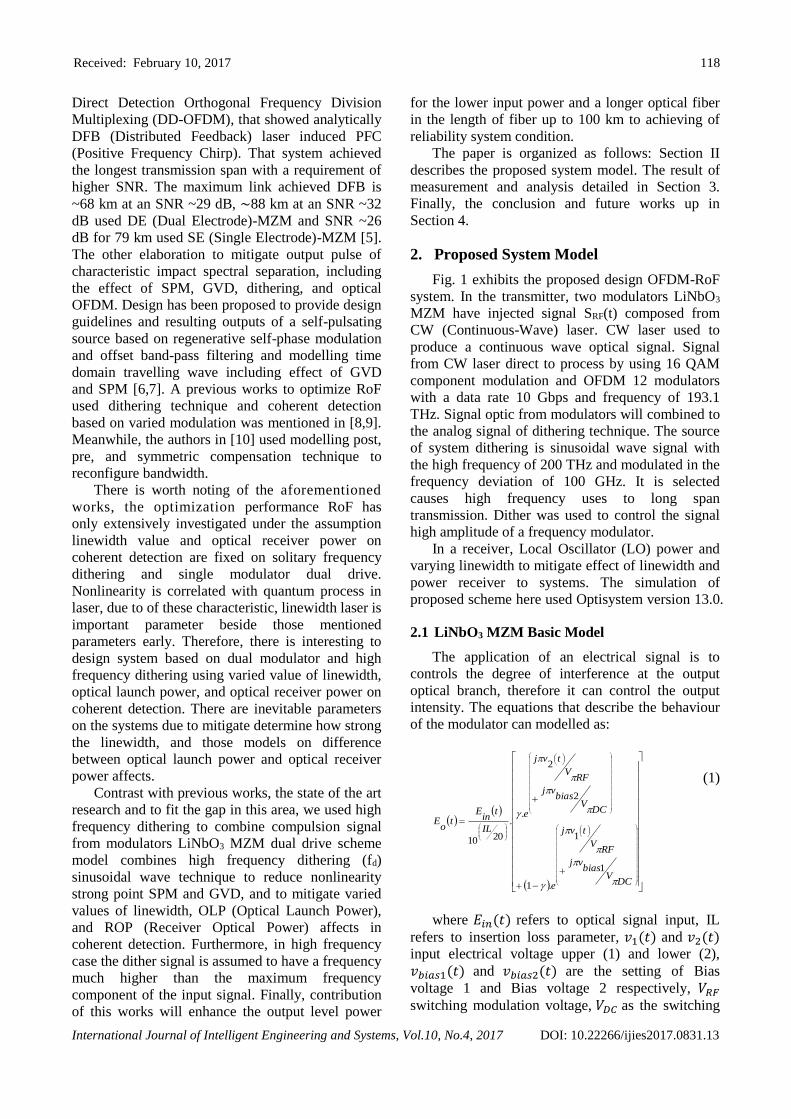
Fig. 1 exhibits the proposed design OFDM-RoF
system. In the transmitter, two modulators LiNbO3
MZM have injected signal SRF(t) composed from
CW (Continuous-Wave) laser. CW laser used to
produce a continuous wave optical signal. Signal
from CW laser direct to process by using 16 QAM
component modulation and OFDM 12 modulators
with a data rate 10 Gbps and frequency of 193.1
THz. Signal optic from modulators will combined to
the analog signal of dithering technique. The source
of system dithering is sinusoidal wave signal with
the high frequency of 200 THz and modulated in the
frequency deviation of 100 GHz. It is selected
causes high frequency uses to long span
transmission. Dither was used to control the signal
high amplitude of a frequency modulator.
In a receiver, Local Oscillator (LO) power and
varying linewidth to mitigate effect of linewidth and
power receiver to systems. The simulation of
proposed scheme here used Optisystem version 13.0.
2.1 LiNbO3 MZM Basic Model
The application of an electrical signal is to
controls the degree of interference at the output
optical branch, therefore it can control the output
intensity. The equations that describe the behaviour
of the modulator can modelled as:
DCV
biasvj
RFV
tvj
e
DCV
biasvj
RFV
tvj
e
IL
tin
Et
oE
1
1
.1
2
2
..
2010
(1)
where 𝐸𝑖𝑛(𝑡) refers to optical signal input, IL
refers to insertion loss parameter, 𝑣1(𝑡) and 𝑣2(𝑡)
input electrical voltage upper (1) and lower (2),
𝑣𝑏𝑖𝑎𝑠1(𝑡) and 𝑣𝑏𝑖𝑎𝑠2(𝑡) are the setting of Bias
voltage 1 and Bias voltage 2 respectively, 𝑉𝑅𝐹
switching modulation voltage, 𝑉𝐷𝐶 as the switching
Received: February 10, 2017 119
International Journal of Intelligent Engineering and Systems, Vol.10, No.4, 2017 DOI: 10.22266/ijies2017.0831.13
Bias voltage, and γ denoted the power splitting ratio of both Y-branch waveguides. Output one modulator
is inclusion from parameter of phase and amplitude
modulation. Mathematical formula of output
modulators is formulated by:
𝐴 =𝐸0
2cos(𝜔𝑡 + ∆𝜃0) +
𝐸0
2cos(𝜔𝑡) (2)
where 𝐴 is information signal from modulator
output, 𝐸0 is carrier of signal, 𝜔𝑡 and ∆𝜃0 each are
modulation based on time function and adjustment
of phase. Based on the same systems and component
inclusion signal of two modulators, which is
formulated as:
𝐴𝑇𝑜𝑡𝑎𝑙 = 2 𝐸0 𝑐𝑜𝑠 1
2(2𝜔𝑡 + ∆𝜃0) cos
1
2(∆𝜃0) (3)
𝐴𝑇𝑜𝑡𝑎𝑙 is total signal compulsion information
two modulators, and 𝐸0 is carrier of signal from two
signal, 𝜔𝑡 and ∆𝜃0 each are modulation based on
time function and adjustment of phase.
2.2 Dithering Technique
Dithering is the process of injection into the
periodic signal for linear or nonlinear system to get
some purpose of which is to add a linear
characteristic of the open/close system.
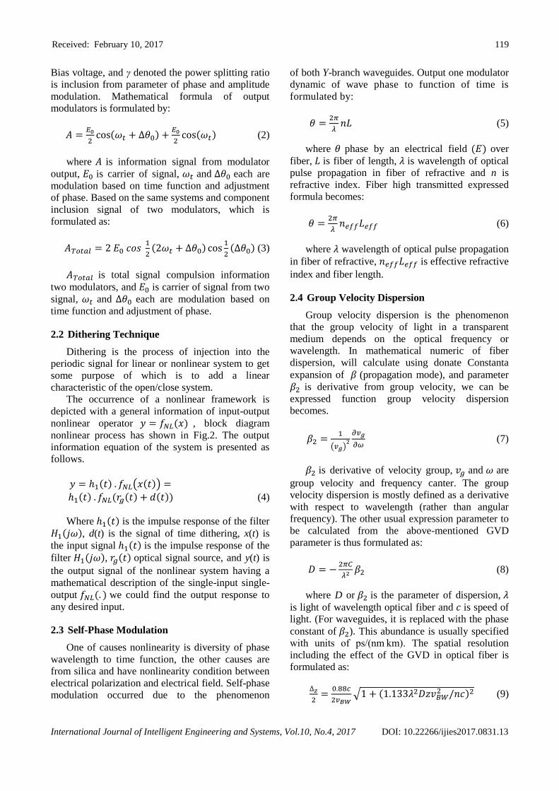
The occurrence of a nonlinear framework is
depicted with a general information of input-output
nonlinear operator 𝑦 = 𝑓𝑁𝐿(𝑥) , block diagram
nonlinear process has shown in Fig.2. The output
information equation of the system is presented as
follows.
𝑦 = ℎ1(𝑡) . 𝑓𝑁𝐿(𝑥(𝑡)) =
ℎ1(𝑡) . 𝑓𝑁𝐿(𝑟𝑔(𝑡) + 𝑑(𝑡)) (4)
Where ℎ1(𝑡) is the impulse response of the filter
𝐻1(𝑗𝜔), d(t) is the signal of time dithering, x(t) is
the input signal ℎ1(𝑡) is the impulse response of the
filter 𝐻1(𝑗𝜔), 𝑟𝑔(𝑡) optical signal source, and y(t) is
the output signal of the nonlinear system having a
mathematical description of the single-input single-
output 𝑓𝑁𝐿(. ) we could find the output response to
any desired input.
2.3 Self-Phase Modulation
One of causes nonlinearity is diversity of phase
wavelength to time function, the other causes are
from silica and have nonlinearity condition between
electrical polarization and electrical field. Self-phase
modulation occurred due to the phenomenon
dynamic of wave phase to function of time is
formulated by:
𝜃 =2𝜋
𝜆𝑛𝐿 (5)
where 𝜃 phase by an electrical field (𝐸) over
fiber, 𝐿 is fiber of length, 𝜆 is wavelength of optical
pulse propagation in fiber of refractive and n is
refractive index. Fiber high transmitted expressed
formula becomes:
𝜃 =2𝜋
𝜆𝑛𝑒𝑓𝑓𝐿𝑒𝑓𝑓 (6)
where 𝜆 wavelength of optical pulse propagation
in fiber of refractive, 𝑛𝑒𝑓𝑓𝐿𝑒𝑓𝑓 is effective refractive
index and fiber length.
2.4 Group Velocity Dispersion
Group velocity dispersion is the phenomenon
that the group velocity of light in a transparent
medium depends on the optical frequency or
wavelength. In mathematical numeric of fiber
dispersion, will calculate using donate Constanta
expansion of 𝛽 (propagation mode), and parameter
𝛽2 is derivative from group velocity, we can be
expressed function group velocity dispersion
becomes.
𝛽2 =1
(𝑣𝑔)2
𝜕𝑣𝑔
𝜕𝜔 (7)
𝛽2 is derivative of velocity group, 𝑣𝑔 and 𝜔 are
group velocity and frequency canter. The group
velocity dispersion is mostly defined as a derivative
with respect to wavelength (rather than angular
frequency). The other usual expression parameter to
be calculated from the above-mentioned GVD
parameter is thus formulated as:
𝐷 = −2𝜋𝐶
𝜆2 𝛽2 (8)
where D or 𝛽2 is the parameter of dispersion, 𝜆
is light of wavelength optical fiber and 𝑐 is speed of
light. (For waveguides, it is replaced with the phase
constant of 𝛽2). This abundance is usually specified
with units of ps/(nm km). The spatial resolution
including the effect of the GVD in optical fiber is
formulated as:
∆𝑧
2=
0.88𝑐
2𝑣𝐵𝑊√1 + (1.133𝜆2𝐷𝑧𝑣𝐵𝑊
2 /𝑛𝑐)2 (9)
Received: February 10, 2017 120
International Journal of Intelligent Engineering and Systems, Vol.10, No.4, 2017 DOI: 10.22266/ijies2017.0831.13
PRBS
Generator
SPM and GVD
EDFA
Dither System
QAM
Modulator
OFDM
Modulator
CW
Laser
MZM
Modulator
Sine
Generator
FM
Modulator
Pumping
Laser
Optical
loop
Optical
Filter
Local
Oscillator
Coherent
DetectionOFDM
Demodulator
QAM
Demodulator
Single
Mode
Fiber
Optical
Amp
MZM
Modulator
Figure.1 Scheme modified of OFDM-RoF using dual modulator and high frequency dithering
fNL (.) H1 (jω) Σrg (t)
d(t)
x(t) y(t)
Figure.2 The output of the nonlinear using high and single frequency fd component
𝜆 is the light wavelength =1.55µm, 𝑛 and 𝑐 are
velocity of light and the refractive index of the fiber
=1.46, D is the GVD = 17.7 ps/nm/km, and different
frequency-chirp ranges 𝑣𝐵𝑊 is 75 GHz and 49 GHz.
3. Measurement and Analysis
Laser linewidth in a typical single-transverse-
mode He-Ne laser (at a wavelength of 632.8 nm), in
the absence of intracavity line narrowing optics, can
be of the order of 1 GHz. Smaller of linewidth value
will be make narrow of pulse duration. On the other
hand, the laser linewidth from stabilized low-power
continuous-wave lasers can be very narrow and
reach down to less than 1 kHz [11]. External
modulation of a single frequency seed could achieve
broadening linewidth.
Fig. 3 until Fig. 5 exhibits the results of the
received power based upon the varied linewidth,
ROP (Receiver Optical Power), and OLP (Optical
Launch Power). Fig. 3 shows the optical received
power where the transmitted power is varied from -8
dBm to 8 dBm to observe the system’s performance
subjects to the nonlinearity with respect to effect of
SPM and GVD. The dithering scheme is applied in
the optical fiber in the length of 50 km and linewidth
of 1 MHz, 3 MHz, and 7 MHz. For each linewidth,
the received power is to approximate the transmitted
level. For 1 MHz linewidth where the transmitted
power 8 dBm the received power level is 137.213
dBm. For 3 MHz linewidth where the transmitted
power is also 8 dBm, the received power level
achieved 137.211 dBm and 7 MHz achieved 137.
209 dBm. In the other transmitted power of -8 dBm
the received power level is 122.414 dBm, and
122.410 dBm and 122.414 dBm dBm in each on 1
MHz, 3 Mhz, 7 MHz linewidth. For 1 MHz
linewidth where the transmitted power is 6 dBm and
4 dBm the received power level each are 135.655
dBm and 133.941 dBm. For 3 MHz linewidth where
the transmitted power is also 6 dBm, the received
power level achieved are 136.654 dBm and 132.125
and 7 MHz achieved are 135. 652 dBm 133.938
dBm. In the other of lower transmitted power -6
dBm the received power level is 122.414 dBm, and
122.410 dBm and 122.414 dBm in each on 1 MHz,
3 Mhz, 7 MHz linewidth, and for -4 dBm the
received power level is 126.366 dBm, 126.363 dBm
and 126.363 dBm. Fig. 3 shows used power
generate composite systems will be boost signal, to
achieve enhancement of power output and compose
a signal robust against noise than conventional
systems.

Received: February 10, 2017 121
International Journal of Intelligent Engineering and Systems, Vol.10, No.4, 2017 DOI: 10.22266/ijies2017.0831.13
(a) (b)
(c)
Figure. 3 Optical received power after and before the application of the proposed power increasing system based on
(a) 1 MHz (b) 3 MHz and (c) 7 MHz linewidth
Figure.4 Systems with varied receiver power based on
Log BER
Figure.5 Systems with varied linewidth based on BER
and SER
Received: February 10, 2017 122
International Journal of Intelligent Engineering and Systems, Vol.10, No.4, 2017 DOI: 10.22266/ijies2017.0831.13
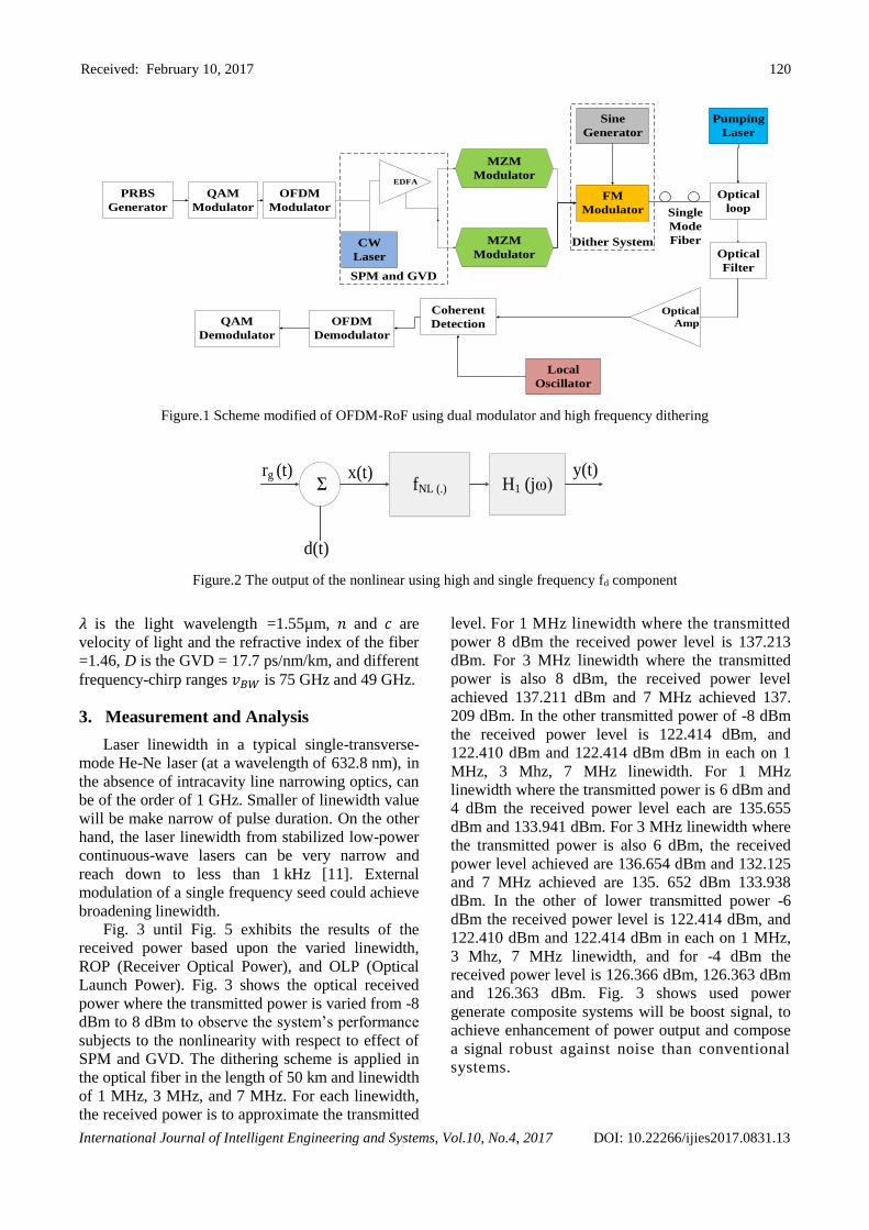
Figure.6 Systems with varied receiver power based on
BER and SER
Fig. 4 and Fig.5 depicts the systems with OLP -8
dBm and varied ROP of 10 dBm, 13 dBm, 15 dBm,
17 dBm and 19 dBm after and before applied
systems. This simulation is intended to determine
how much influence the suitability between OLP
and optical receiver power based on Log BER, BER,
and SER (Symbol Error Rate). On receiver power
10 dBm, 13 dBm, 15 dBm, 17 dBm and 19 dBm,
achieved log BER each other are -1.44, -1.926,
-1.696, -2.449, and -2.407. The value achieved of
simulation shows between OLP and receiver power
has influential, the best condition achieved when the
value of receiver power more then to the OLP. That
will be make a easy to synchronisation power and
phase with a high power in receiver. The simulation
shows the best log10 BER found was -2.407 on
power received 17dBm. The best BER and SER
achieved 0.003 on power received by 17 dBm and
0.007 on 19 dBm.
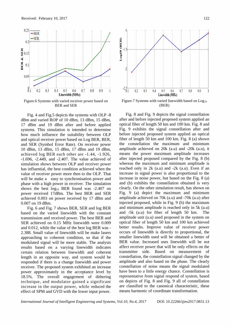
Fig. 6 and Fig. 7 shows BER, SER and log BER
based on the varied linewidth with the constant
transmission and received power. The best BER and
SER achieved on 0.15 MHz linewidth were 0.009
and 0.012, while the value of the best log BER was -
2.388. Small value of linewidth will be make lasers
approaching to coherent condition, so that if the
modulated signal will be more stable. The analysis
results based on a varying linewidth indicates
certain relation between linewidth and coherent
length in an opposite way, and system would be
responded if there is a change linewidth and power
receiver. The proposed system exhibited an increase
power approximately in the acceptance level by
18.5%. The overall engagement of dithering
technique, and modulator gained a significant
increase in the output power, while reduced the
effect of SPM and GVD with the lower input power.
Figure.7 Systems with varied linewidth based on Log10
(BER)
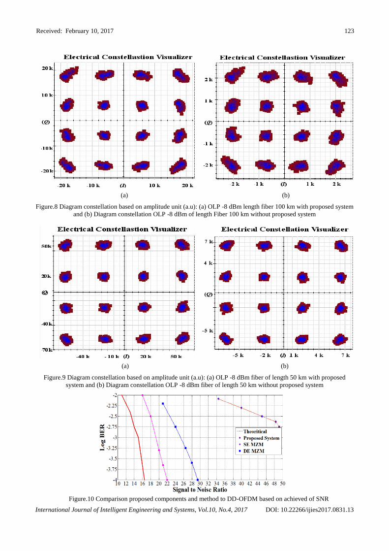
Fig. 8 and Fig. 9 depicts the signal constellation
after and before injected proposed system applied an
optical fiber of length 50 km and 100 km. Fig. 8 and
Fig. 9 exhibits the signal constellation after and
before injected proposed system applied an optical
fiber of length 50 km and 100 km. Fig. 8 (a) shown
the constellation the maximum and minimum
amplitude achieved on 20k (a.u) and -20k (a.u), it
means the power maximum amplitude increases
after injected proposed compared by the Fig. 8 (b)
whereas the maximum and minimum amplitude is
reached only in 2k (a.u) and -2k (a.u). Even if an
increase in signal power is also proportional to the
increase in noise power, but based on the Fig. 8 (a)
and (b) exhibits the constellation obtained is very
clearly. On the other simulation result, has shown on
Fig. 9 (a) depict the maximum and minimum
amplitude achieved on 70k (a.u) and -70k (a.u) after
injected proposed, while in Fig. 9 (b) the maximum
and minimum amplitude is reached only in 5k (a.u)
and -5k (a.u) for fiber of length 50 km. The
amplitude unit (a.u) used proposed in the system on
optical fiber of length 50 km and 100 km achieved
better results. Improve value of receiver power
occurs of linewidth is directly to proportional, the
smaller linewidth used will be obtained a better of
BER value. Increased uses linewidth will be not
affect receiver power that will be only effects on the
transmitter side. Based on measurement of
constellation, the constellation signal changed by the
amplitude and also based on the phase. The clearly
constellation of noise means the signal modulated
have been to a little energy chance. Constellation is
representative from signal respond of system, based
on depicts of Fig. 8 and Fig. 9 all of constellation
are classified to the canonical characteristic, these
means harmonic of coordinate transformation.
Received: February 10, 2017 123
International Journal of Intelligent Engineering and Systems, Vol.10, No.4, 2017 DOI: 10.22266/ijies2017.0831.13
(a) (b)
Figure.8 Diagram constellation based on amplitude unit (a.u): (a) OLP -8 dBm length fiber 100 km with proposed system
and (b) Diagram constellation OLP -8 dBm of length Fiber 100 km without proposed system
(a) (b)
Figure.9 Diagram constellation based on amplitude unit (a.u): (a) OLP -8 dBm fiber of length 50 km with proposed
system and (b) Diagram constellation OLP -8 dBm fiber of length 50 km without proposed system
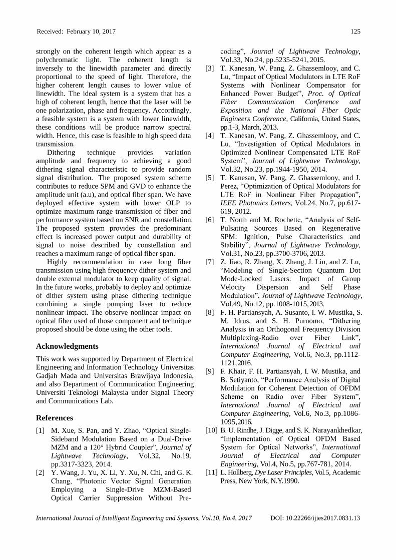
Figure.10 Comparison proposed components and method to DD-OFDM based on achieved of SNR
Received: February 10, 2017 124
International Journal of Intelligent Engineering and Systems, Vol.10, No.4, 2017 DOI: 10.22266/ijies2017.0831.13
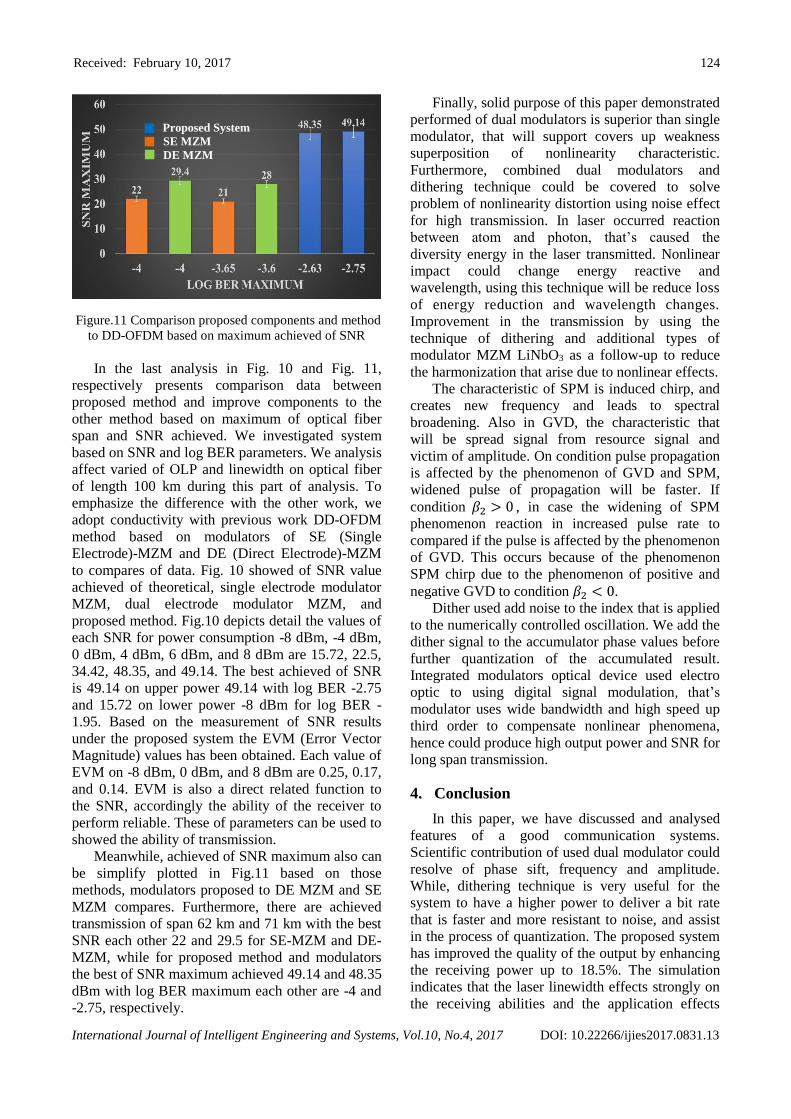
Figure.11 Comparison proposed components and method
to DD-OFDM based on maximum achieved of SNR
In the last analysis in Fig. 10 and Fig. 11,
respectively presents comparison data between
proposed method and improve components to the
other method based on maximum of optical fiber
span and SNR achieved. We investigated system
based on SNR and log BER parameters. We analysis
affect varied of OLP and linewidth on optical fiber
of length 100 km during this part of analysis. To
emphasize the difference with the other work, we
adopt conductivity with previous work DD-OFDM
method based on modulators of SE (Single
Electrode)-MZM and DE (Direct Electrode)-MZM
to compares of data. Fig. 10 showed of SNR value
achieved of theoretical, single electrode modulator
MZM, dual electrode modulator MZM, and
proposed method. Fig.10 depicts detail the values of
each SNR for power consumption -8 dBm, -4 dBm,
0 dBm, 4 dBm, 6 dBm, and 8 dBm are 15.72, 22.5,
34.42, 48.35, and 49.14. The best achieved of SNR
is 49.14 on upper power 49.14 with log BER -2.75
and 15.72 on lower power -8 dBm for log BER -
1.95. Based on the measurement of SNR results
under the proposed system the EVM (Error Vector
Magnitude) values has been obtained. Each value of
EVM on -8 dBm, 0 dBm, and 8 dBm are 0.25, 0.17,
and 0.14. EVM is also a direct related function to
the SNR, accordingly the ability of the receiver to
perform reliable. These of parameters can be used to
showed the ability of transmission.
Meanwhile, achieved of SNR maximum also can
be simplify plotted in Fig.11 based on those
methods, modulators proposed to DE MZM and SE
MZM compares. Furthermore, there are achieved
transmission of span 62 km and 71 km with the best
SNR each other 22 and 29.5 for SE-MZM and DE-
MZM, while for proposed method and modulators
the best of SNR maximum achieved 49.14 and 48.35
dBm with log BER maximum each other are -4 and
-2.75, respectively.
Finally, solid purpose of this paper demonstrated
performed of dual modulators is superior than single
modulator, that will support covers up weakness
superposition of nonlinearity characteristic.
Furthermore, combined dual modulators and
dithering technique could be covered to solve
problem of nonlinearity distortion using noise effect
for high transmission. In laser occurred reaction
between atom and photon, that’s caused the
diversity energy in the laser transmitted. Nonlinear
impact could change energy reactive and
wavelength, using this technique will be reduce loss
of energy reduction and wavelength changes.
Improvement in the transmission by using the
technique of dithering and additional types of
modulator MZM LiNbO3 as a follow-up to reduce
the harmonization that arise due to nonlinear effects.
The characteristic of SPM is induced chirp, and
creates new frequency and leads to spectral
broadening. Also in GVD, the characteristic that
will be spread signal from resource signal and
victim of amplitude. On condition pulse propagation
is affected by the phenomenon of GVD and SPM,
widened pulse of propagation will be faster. If
condition 𝛽2 > 0 , in case the widening of SPM
phenomenon reaction in increased pulse rate to
compared if the pulse is affected by the phenomenon
of GVD. This occurs because of the phenomenon
SPM chirp due to the phenomenon of positive and
negative GVD to condition 𝛽2 < 0.
Dither used add noise to the index that is applied
to the numerically controlled oscillation. We add the
dither signal to the accumulator phase values before
further quantization of the accumulated result.
Integrated modulators optical device used electro
optic to using digital signal modulation, that’s
modulator uses wide bandwidth and high speed up
third order to compensate nonlinear phenomena,
hence could produce high output power and SNR for
long span transmission.
4. Conclusion
In this paper, we have discussed and analysed
features of a good communication systems.
Scientific contribution of used dual modulator could
resolve of phase sift, frequency and amplitude.
While, dithering technique is very useful for the
system to have a higher power to deliver a bit rate
that is faster and more resistant to noise, and assist
in the process of quantization. The proposed system
has improved the quality of the output by enhancing
the receiving power up to 18.5%. The simulation
indicates that the laser linewidth effects strongly on
the receiving abilities and the application effects
Proposed System
SE MZM
DE MZM
Received: February 10, 2017 125
International Journal of Intelligent Engineering and Systems, Vol.10, No.4, 2017 DOI: 10.22266/ijies2017.0831.13
strongly on the coherent length which appear as a
polychromatic light. The coherent length is
inversely to the linewidth parameter and directly
proportional to the speed of light. Therefore, the
higher coherent length causes to lower value of
linewidth. The ideal system is a system that has a
high of coherent length, hence that the laser will be
one polarization, phase and frequency. Accordingly,
a feasible system is a system with lower linewidth,
these conditions will be produce narrow spectral
width. Hence, this case is feasible to high speed data
transmission.
Dithering technique provides variation
amplitude and frequency to achieving a good
dithering signal characteristic to provide random
signal distribution. The proposed system scheme
contributes to reduce SPM and GVD to enhance the
amplitude unit (a.u), and optical fiber span. We have
deployed effective system with lower OLP to
optimize maximum range transmission of fiber and
performance system based on SNR and constellation.
The proposed system provides the predominant
effect is increased power output and durability of
signal to noise described by constellation and
reaches a maximum range of optical fiber span.
Highly recommendation in case long fiber
transmission using high frequency dither system and
double external modulator to keep quality of signal.
In the future works, probably to deploy and optimize
of dither system using phase dithering technique
combining a single pumping laser to reduce
nonlinear impact. The observe nonlinear impact on
optical fiber used of those component and technique
proposed should be done using the other tools.
Acknowledgments
This work was supported by Department of Electrical
Engineering and Information Technology Universitas
Gadjah Mada and Universitas Brawijaya Indonesia,
and also Department of Communication Engineering
Universiti Teknologi Malaysia under Signal Theory
and Communications Lab.
References
[1] M. Xue, S. Pan, and Y. Zhao, “Optical Single-
Sideband Modulation Based on a Dual-Drive
MZM and a 120° Hybrid Coupler”, Journal of
Lightwave Technology, Vol.32, No.19,
pp.3317-3323, 2014.
[2] Y. Wang, J. Yu, X. Li, Y. Xu, N. Chi, and G. K.
Chang, “Photonic Vector Signal Generation
Employing a Single-Drive MZM-Based
Optical Carrier Suppression Without Pre-
coding”, Journal of Lightwave Technology,
Vol.33, No.24, pp.5235-5241, 2015.
[3] T. Kanesan, W. Pang, Z. Ghassemlooy, and C.
Lu, “Impact of Optical Modulators in LTE RoF
Systems with Nonlinear Compensator for
Enhanced Power Budget”, Proc. of Optical
Fiber Communication Conference and
Exposition and the National Fiber Optic
Engineers Conference, California, United States,
pp.1-3, March, 2013.
[4] T. Kanesan, W. Pang, Z. Ghassemlooy, and C.
Lu, “Investigation of Optical Modulators in
Optimized Nonlinear Compensated LTE RoF
System”, Journal of Lightwave Technology,
Vol.32, No.23, pp.1944-1950, 2014.
[5] T. Kanesan, W. Pang, Z. Ghassemlooy, and J.
Perez, “Optimization of Optical Modulators for
LTE RoF in Nonlinear Fiber Propagation”,
IEEE Photonics Letters, Vol.24, No.7, pp.617-
619, 2012.
[6] T. North and M. Rochette, “Analysis of Self-
Pulsating Sources Based on Regenerative
SPM: Ignition, Pulse Characteristics and
Stability”, Journal of Lightwave Technology,
Vol.31, No.23, pp.3700-3706, 2013.
[7] Z. Jiao, R. Zhang, X. Zhang, J. Liu, and Z. Lu,
“Modeling of Single-Section Quantum Dot
Mode-Locked Lasers: Impact of Group
Velocity Dispersion and Self Phase
Modulation”, Journal of Lightwave Technology,
Vol.49, No.12, pp.1008-1015, 2013.
[8] F. H. Partiansyah, A. Susanto, I. W. Mustika, S.
M. Idrus, and S. H. Purnomo, “Dithering
Analysis in an Orthogonal Frequency Division
Multiplexing-Radio over Fiber Link”,
International Journal of Electrical and
Computer Engineering, Vol.6, No.3, pp.1112-
1121, 2016.
[9] F. Khair, F. H. Partiansyah, I. W. Mustika, and
B. Setiyanto, “Performance Analysis of Digital
Modulation for Coherent Detection of OFDM
Scheme on Radio over Fiber System”,
International Journal of Electrical and
Computer Engineering, Vol.6, No.3, pp.1086-
1095, 2016.
[10] B. U. Rindhe, J. Digge, and S. K. Narayankhedkar,
“Implementation of Optical OFDM Based
System for Optical Networks”, International
Journal of Electrical and Computer
Engineering, Vol.4, No.5, pp.767-781, 2014.
[11] L. Hollberg, Dye Laser Principles, Vol.5, Academic
Press, New York, N.Y.1990.