A New Technique for Shaping Axis-Symmetric Dual-Reflector ...

International Journal of Science, Engineering and Technology Research (IJSETR), Volume 4, Issue 12, December 2015
4170
ISSN: 2278 – 7798 All Rights Reserved © 2015 IJSETR
Abstract: This paper proposes a novel controlled
technique for Dual three phase topology of unified power
quality conditioner (dUPQC) adopted to compensate
current and voltage quality problems of Non-linear loads.
This project tends look at the solving the problems by
using custom power devices by Dual Unified Power
Quality Conditioner (dUPQC) using Fuzzy Logic
Controller. A Fuzzy Logic controller is based on fuzzy sets
and fuzzy rules with their membership functions of inputs
and outputs. A Control technique of two active filters is to
control the sinusoidal references. In dUPQC, series Active
Filter (SAF) works as a current source and Parallel Active
Filter(PAF) works as a voltage source different from a
conventional UPQC and due to these there is a high and
low impedances occurs which is indirectly compensates
the harmonics and disturbance of the grid voltage and
load current and also impedance path is low harmonic at
load current. To deal with sinusoidal reference for well-
known frequency spectrum, a technique of pulse width
modulation (PWM) is used. The proposed system can be
able to compensate the non linear load condition and also
ensure the sinusoidal voltage for the load in all the three
phases. This results in the better power quality. It is
important to note that the existing UPQC topology does
not have this capability. A simulation design control,
power flow analysis is proposed in Dual unified power
quality conditioner and to eliminate harmonics using
Fuzzy Logic controller (FLC). The simulation is verified
using MATLAB/SIMULINK.
Keywords : UPQC, Active Filters : SAF and PAF, Fuzzy
Logic controller, Power Line conditioner, PWM.
I.INTRODUCTION
Presently, power quality problems in grid-integrated
applications take great interest because of the growing
applications in power electronics. Due to increasing
complexity in the power system, power quality problems are
most significant problems. If the power quality problem
surpasses, leads to major problems, which ultimately leads
to wastage of resources as well as financial losses. Non
linear loads always reduces the power quality at electrical
grid and contain a high harmonic content which effect the
critical loads. To overcome such problems we are using a
Unified power quality conditioners. The usage of power
quality conditioners in the distribution system network has
increased during the past years due to the steady increase of
nonlinear loads connected to the electrical grid. The current
exhausted by nonlinear loads has a high harmonic content,
distorting the voltage at the utility grid and consequently
affecting the operation of critical loads. By using a unified
power quality conditioner (UPQC), it is possible to ensure a
regulated voltage for the loads, balanced and with low
harmonic distortion and at the same time exhausting
undistorted currents from the utility grid, even if the grid
voltage and the load current have harmonic contents.
In UPQC they are two types of filters SAF and PAF, PAF
is a current source and SAF is a voltage source both of them
are a non-sinusoidal reference and also compensate the
harmonic in grid voltage and load current. It is a complex
method to solve such problems we are using active filters to
control the harmonics and to eliminate harmonics using
fuzzy controller. Its conditioner consists of two single-phase
current source inverters where the SAF is controlled by a
current loop and the PAF is controlled by a voltage loop both
of them are interconnected to fuzzy controller and grid
current and load voltage are sinusoidal, and therefore, their
references are also sinusoidal. This concept is called “dual
topology of unified power quality conditioner” (iUPQC),
and the control schemes use the p−q theory, for a real time
of positive sequence . The aim of this paper is to propose a
novel controlled technique for Dual unified Power Quality
Conditioner for power quality improvement to eliminate the
harmonics from source to load . In ABC reference frame, the
proposed control scheme is developed for the classical
control theory is without the need for coordinate
transformers and digital control implementation. The
references to both SAF and PAF with fuzzy logic controller
is a pure sinusoidal, dispensing the harmonic extraction from
the grid current and load voltage.
II. DUAL UNIFIED POWER QUALITY
CONDITIONER (dUPQC)
Dual Unified power quality conditioner (dUPQC) its
structure is shown in Fig.1. Different from a conventional
UPQC, in dUPQC, the SAF works as a current source and
PAF works as a voltage source both of them are
synchronized with the grid voltage uses sinusoidal
A Novel Controlled Technique for a Dual
Unified Power Quality Conditioner
P. Lavanya Rekha1, K.V.Sai Kumar
2
PG Student, Department of EEE, KIET, Kakinada, India.1
Asst. Professor, Department of EEE, KIET, Kakinada, India.2
International Journal of Science, Engineering and Technology Research (IJSETR), Volume 4, Issue 12, December 2015
4171
ISSN: 2278 – 7798 All Rights Reserved © 2015 IJSETR
references to the classical topology for both active filters.
The high impedance occurs at SAF to indirectly compensate
the harmonics, unbalances, and disturbances of the grid
voltage. The connection transformer voltages are equal to
the difference between the grid voltage and the load voltage.
In the same way, the PAF indirectly compensates the
unbalances, displacement, and harmonics of the grid
current, providing a low-impedance path for the harmonic
load current.
Fig. 1. Dual UPQC (dUPQC)
III. FUZZY LOGIC CONTROL
FLC determined by the set of linguistic rules. The
mathematical modeling is not required in fuzzy controller
due to the conversion of numerical variable into linguistic
variables. FLC consists of three part: a. Fuzzification, b.
Interference engine, c. Defuzzification. The fuzzy controller
is characterized as; For each input and output there are
seven fuzzy sets. For simplicity a membership functions is
Triangular. Fuzzification is using continuous universe of
discourse. Implication is using Mamdani's "min" operator.
Defuzzification is using the "height" method. FLC block
diagram as shown in figure 2.
Fig. 2. Fuzzy Logic Controller
a. Fuzzification
Membership function values are assigned to the
linguistic variables, using seven fuzzy subsets:
NB(Negative Big), NM(Negative Medium), NS (Negative
Small), ZE (Zero), PS (Positive Small),PM(Positive
Medium) and PB (Positive Big). The partition of fuzzy
subsets and the shape of membership function adapt the
shape up to appropriate system. Input error E(k) and
change in error CE(k) of values which is normalized by an
input scaling factor as shown in table 1.
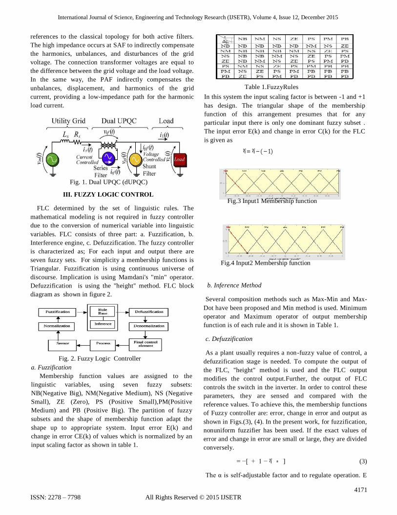
Table 1.FuzzyRules
In this system the input scaling factor is between -1 and +1
has design. The triangular shape of the membership
function of this arrangement presumes that for any
particular input there is only one dominant fuzzy subset .
The input error E(k) and change in error C(k) for the FLC
is given as
ሻ = ሻ − ( − 1)
Fig.3 Input1 Membership function
Fig.4 Input2 Membership function
b. Inference Method
Several composition methods such as Max-Min and Max-
Dot have been proposed and Min method is used. Minimum
operator and Maximum operator of output membership
function is of each rule and it is shown in Table 1.
c. Defuzzification
As a plant usually requires a non-fuzzy value of control, a
defuzzification stage is needed. To compute the output of
the FLC, "height" method is used and the FLC output
modifies the control output.Further, the output of FLC
controls the switch in the inverter. In order to control these
parameters, they are sensed and compared with the
reference values. To achieve this, the membership functions
of Fuzzy controller are: error, change in error and output as
shown in Figs.(3), (4). In the present work, for fuzzification,
nonuniform fuzzifier has been used. If the exact values of
error and change in error are small or large, they are divided
conversely.
= −[ + 1 − ሻ ∗ ] (3)
The α is self-adjustable factor and to regulate operation. E

International Journal of Science, Engineering and Technology Research (IJSETR), Volume 4, Issue 12, December 2015
4172
ISSN: 2278 – 7798 All Rights Reserved © 2015 IJSETR
is the error of the system, C is the change in error and u is
the control variable. If the system is not in balanced it
indicates an error 'E' if the value is large. While the error 'E'
value is small it indicates that the system is near to balanced
state. If system is unbalanced, the control variables should
be enlarge to balance the system as early as possible. For
system stability overshoot plays an important role. For
restraining oscillations and system stability it requires less
overshoot. 'C' plays an important role, while the role of 'E' is
diminished. The optimization is done by α. The set of Fuzzy
controller rules is given in Table 1.
IV. POWER CIRCUIT
The power circuit of the proposed scheme of dUPQC is
made up of two four-wire three-phase converters connected
back to back and their respective output filters, as shown in
Fig.5. Three single-phase transformers are used to connect
the SAF to the utility grid, and PAF is connected to the
load. The design specifications of the dUPQC as shown in
Table 3. The passive components are shown in Table 2.
Fig.5 Power circuit of the dUPQC.
TABLE 1
Leakage inductance of SAF coupling
Transformer
Llg=2.33mH
Transformer ratio of the SAF
coupling Transformer
n=1
SAF connection inductance Lsf=650µH
PAF connection inductance Lpf=650µH
DC Link Capacitance Cb =3mF
TABLE2: COMPONENT SPECIFICATION OF POWER MODULES
V. OUTPUT PASSIVE FILTER DESIGN
Single-phase wiring diagram ofdUPQC, is shown in Fig. 6.
The grid impedance is Zs = jωLs + Rs, and leakage
impedance of coupling transformer is Zlg = jωLlg + Rlg, in
series and shunt filters, the voltage sources is vsc and vpc
and the harmonic which are generated from the switches are
composed by the components. The high frequency of
iUPQC is filtered by the output passive filters for sinusoidal
grid current and load voltage as shown in Fig.6.
Fig.6 Single-phase wiring diagram of the dual UPQC
SAF and PAF output impedances is as shown in Fig.7 and
Fig.8. The current source is in series and connected to
voltage source vsc and inductance Lsf, in PAF. The transfer
function of PAF in high-frequency filter is derived in
equation (1) and circuit is shown in Fig.8.
Fig.7 Equivalent circuit as viewed by SAF.
Fig.8 Equivalent circuit as viewed by PAF
The high frequency filter transfer function of the PAF is
derived by analysing the circuit as shown in Fig.8.
Power design of inductor Lpf and cut off frequency of filter
capacitor Cpf which is of 2.9 kHz and 10μF. The transfer
function of SAF in high-frequency filter is derived in
equation (2) and circuit is shown in Fig.7. and also the α,β,γ
equations (3),(4) and (5).
Input line to line RMS voltage Vin=220V
Output nominal power Po=2500VA
DC link voltage Vb=400V
Utility grid frequency fgrid=50Hz
Switching frequency of
SAFs and PAFs fs=20KHz Transformer ratio n=1
International Journal of Science, Engineering and Technology Research (IJSETR), Volume 4, Issue 12, December 2015
4173
ISSN: 2278 – 7798 All Rights Reserved © 2015 IJSETR
Here cutoff frequency of filter capacitor Cpf which is of 45-
kHz and 1μF. The low cutoff frequency response is to reduce
the filter bandwidth of the SAF, and grid voltage contents the
harmonic. The leakage impedance of coupling transformers is
of low-frequency attenuation is undesirable and intrinsic
towards the characteristic. As per the previous articles, it deal
with the same dUPQC control strategy, the output filter of
inductor is impose of voltage and SAF current and through the
filter its frequency is sinusoidal with current. It is a narrow
band frequency control to distort the current drained from the
utility grid. The usage of high-power coupling transformers,
with low leakage inductance, and the design of higher voltage
dc link, allowing the imposition of higher current rate of
change on the filter output inductor, and solutions to change
the characteristics of the filter in low frequencies.
VI. PROPOSED CONTROL SCHEME
The proposed iUPQC control structure is an ABC reference
frame based on the compensation of harmonics, unbalances,
disturbances, and displacement . To compensate we are using
the SAF is a current loop and PAF is a voltage loop in order
to ensure the sinusoidal grid current and load voltage with low
harmonic distortion. The dc link voltage is a reference
amplitude for the current loop, in the power factor converter
control schemes of SAF. With the sinusoidal references for
both SAF and PAF controllers are generated by a digital signal
processor (DSP), and to ensure the grid voltage synchronism
using a phase locked loop.
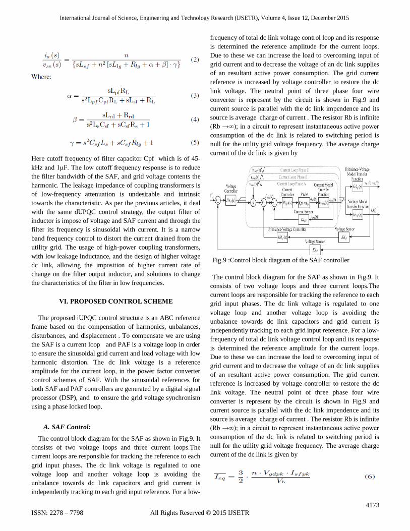
A. SAF Control:
The control block diagram for the SAF as shown in Fig.9. It
consists of two voltage loops and three current loops.The
current loops are responsible for tracking the reference to each
grid input phases. The dc link voltage is regulated to one
voltage loop and another voltage loop is avoiding the
unbalance towards dc link capacitors and grid current is
independently tracking to each grid input reference. For a low-
frequency of total dc link voltage control loop and its response
is determined the reference amplitude for the current loops.
Due to these we can increase the load to overcoming input of
grid current and to decrease the voltage of an dc link supplies
of an resultant active power consumption. The grid current
reference is increased by voltage controller to restore the dc
link voltage. The neutral point of three phase four wire
converter is represent by the circuit is shown in Fig.9 and
current source is parallel with the dc link impendence and its
source is average charge of current . The resistor Rb is infinite
(Rb →∞); in a circuit to represent instantaneous active power
consumption of the dc link is related to switching period is
null for the utility grid voltage frequency. The average charge
current of the dc link is given by
Fig.9 :Control block diagram of the SAF controller
The control block diagram for the SAF as shown in Fig.9. It
consists of two voltage loops and three current loops.The
current loops are responsible for tracking the reference to each
grid input phases. The dc link voltage is regulated to one
voltage loop and another voltage loop is avoiding the
unbalance towards dc link capacitors and grid current is
independently tracking to each grid input reference. For a low-
frequency of total dc link voltage control loop and its response
is determined the reference amplitude for the current loops.
Due to these we can increase the load to overcoming input of
grid current and to decrease the voltage of an dc link supplies
of an resultant active power consumption. The grid current
reference is increased by voltage controller to restore the dc
link voltage. The neutral point of three phase four wire
converter is represent by the circuit is shown in Fig.9 and
current source is parallel with the dc link impendence and its
source is average charge of current . The resistor Rb is infinite
(Rb →∞); in a circuit to represent instantaneous active power
consumption of the dc link is related to switching period is
null for the utility grid voltage frequency. The average charge
current of the dc link is given by

International Journal of Science, Engineering and Technology Research (IJSETR), Volume 4, Issue 12, December 2015
4174
ISSN: 2278 – 7798 All Rights Reserved © 2015 IJSETR
Through equation (6), the voltage loop transfer fumction is
obtained and is presented by equation (7)
Where: Vgdpk - Peak of grid voltage;
Vb - dc link voltage;
Rb - load equivalent resistance;
Cb - Total dc link equivalent capacitance;
n - Transformer ratio;
The open loop transfer function (OLTFv) is given by
equation (8):
Where: Kmfs - Multiplier gain;
Kvsf - Voltage sensor gain;
Kisf - Current sensor gain;
Fig.10 Equivalent circuit of the SAF voltage loop.
Fig.11 Single-phase equivalent circuit of SAF
A proportional integral (PI) controller is designed to regulate,
and ensures a crossover frequency of 4 Hz and a phase margin
of 45◦ with total voltage loop frequency, and including the
open-loop transfer function (OLTFv), controller transfer
function (Hvsf ), compensated loop transfer function
(OLTFv+ Hvsf ). Under the unbalanced voltage loop condition
the grid current reference is CL1 and CL2 is equilibrium the
voltage loop in a dc link capacitor. To analysis of these
function a current isc(t) is a neutral point, and d(t) is a duty
cycle. The single-phase four wire convertor is of two current
sources on the inverter switches. The unbalanced voltage loop
transfer function is obtained by mesh analysis and Laplace is
given by
The open-loop transfer function (OLT Fd) is given by eqn (10)
A proportional integral (PI) controller is designed to eliminate,
and ensures a crossover frequency of 0.5Hz and a phase
margin of 50◦ with frequency of differential voltage loop , and
including the open-loop transfer function (OLTFd), controller
transfer function (Hdsf ), compensated loop transfer function
(OLTFd + Hdsf ). It consists of three identical current loops,
except for the 120◦ phase displacements. To decoupling the
voltage loop and its source on the coupling transformer and
the current loop transfer function as shown in Fig.11.The
dynamic model of an circuit has an average value related to
the switching period and voltage vs(t) and vL(t) are constants.
The current loop transfer function and small signal is analyzed
by Laplace is given by
and Ls - series grid
in
Rs – series grid resistance
Llg – Leakage inductance of the coupling transformer
Rlg – Series resistance of the coupling transformer
The open loop transfer function (OLTFi) is given by eqn (13)
Where
K pwmsf - Series filter PWM modulator gain;
The K pwmsf gain equals the inverse peak value of the
triangular carrier. A proportional integral (PI) controller is
designed to tack the current reference, and ensures a crossover
frequency of 5 kHz and a phase margin of 70◦ with frequency
response of current loop, and including the open-loop transfer
function (OLTFi), controller transfer function (Hisf ),
compensated loop transfer function (OLTFi + Hisf ).

International Journal of Science, Engineering and Technology Research (IJSETR), Volume 4, Issue 12, December 2015
4175
ISSN: 2278 – 7798 All Rights Reserved © 2015 IJSETR
B. PAF Control
A control block diagram of shunt active filter is shown in
Fig.12.The control scheme of three identical load voltage
and towards feedback loops in 120◦ phase displacement.
Fig.12 Control block diagram of the PAF voltage loop
The transfer function of voltage loop is analyzed by a
single-phase equivalent circuit as shown in Fig.13.The
voltage loop transfer function is using average values for
switching period and small signal is analyzed by Laplace is
given
Fig.13 Single-phase equivalent circuit of PAF.
Where Gvpf (s) = VL (s)/D(s).
The open loop transfer function (OLT F vpf ) is given by
equation(15):
Where:
K pwmpf - Shunt filter PWM modulator gain;
An additional (PID) pole controller is designed to track the
voltage reference, and ensures a crossover frequency in a
proportional integral derivate of 4 kHz and a phase margin
of 35◦ with frequency response of voltage loop, and
including the open-loop transfer function (OLTFvpf ),
controller transfer function (Hvpf ), compensated loop
transfer function (OLTFvpf + Hvpf ).
VII. SIMULATION OF dUPQC AND SIMULINK
RESULTS
Simulation was built in several steps from grid source to
load, Dual UPQC operation at different loads is as shown in
figure 14. Power Circuit of DUPQC is made up of two four
wire three-phase converters connected back-back and their
respective output filters as shown in figure 15. The Control
structure is an ABC reference frame based where SAF and
PAF are controlled in an independent way. SAF Control block
is as shown in figure 16 and PAF control block is as shown in
figure 17.
Fig. 14 Simulink design of Dual UPQC
Fig. 16 SAF Control Block

International Journal of Science, Engineering and Technology Research (IJSETR), Volume 4, Issue 12, December 2015
4176
ISSN: 2278 – 7798 All Rights Reserved © 2015 IJSETR
Fig. 15 Power Circuit of Dual UPQC
Fig. 17 PAF Control Block
The result is obtained through fuzzy based Dual Unified
Power Quality Conditioner for power quality improvement.
From grid source to load we are eliminating the harmonics
using SAF and PAF filters and Fuzzy Logic Controller and
injecting the dip voltage and compensating with DC link
current load to discrete the RMS voltage. Hence the result
output is without harmonics from grid source to load.
FIG.18.(a) Source Voltages (Vabc )(200V/div, 5ms/div)
FIG.18.(b)Source Current (Iabc) ( 20A/div, 5ms/div)
Fig.18.(c) Load Voltage (Vabcl) (200V/div, 5ms/div)
Fig.18.(d) Load Current (Iabcl)(20A/div, 5ms/div)
Fig.18.(e) PAF Currents (IFabc) (10A/div, 5ms/div)
Fig.18. (f) SAF Voltages (VFabc) (20V/div, 2.5ms/div)

International Journal of Science, Engineering and Technology Research (IJSETR), Volume 4, Issue 12, December 2015
4177
ISSN: 2278 – 7798 All Rights Reserved © 2015 IJSETR
Fig 19(a) Waveform of three phase source voltages with
voltage dip in phase A and load voltage with FLC.
Fig 19(b) Waveform of three phase load voltage and source
currents during a voltage dip in phase A with FLC
Fig 19(c) Waveform of three phase Load Voltages (200V/div,
5ms/div) and Load Currents (10A/div, 5ms/div) during a load
step from 50% to 100% with FLC .
Fig 19 (d) Waveform of Load Voltages (200V/div, 5ms/div)
and Load Currents (10A/div, 5ms/div)during a load step from
100% to 50% with FLC.
Fig 19(e) Waveform of DC Link Voltages (100V/div,
50ms/div) and Load currents (10A/div, 50ms/div) during a
load step from 100% to 50% with FLC.
VIII. CONCLUSION
The results obtained with iUPQC using Fuzzy Logic
Controller and design with Matlab Simulation Technique in
ABC reference frame works very well and was able to
compensate the harmonics from nonlinear load current. The
proposed scheme of iUPQC using fuzzy controller in ABC
reference frame of both the active filters and their control
loops are generated by a digital control system blocks and to
related to other proposed controls its utilization is better for
a sinusoidal reference and to eliminate the harmonic from
source to load. The main advantages of this proposed
control in relation to other proposed schemes were the
utilization of sinusoidal references for both series and shunt
active filters controls without the need for complex
calculations or coordinate transformations..Both the active
filters from source to load are dip by the RMS voltage in
phase ''A'' to eliminate the harmonics from grid source
voltage to load current using fuzzy controller. The results
validate the proposed dUPQC control scheme proving that
the power quality can be meaningfully better with Fuzzy
controller which uses only synchronized sinusoidal
references.
REFERENCES
[1] Raphael J. Millnitz dos Santos, Jean Carlo da Cunha, and
Marcello Mezaroba, Member, IEEE “A Simplified Control
Technique for a Dual Unified Power Quality Conditioner”,
ieee transaction on industrial electronics,vol.61.no.11,Nov
2014.
[2] M. Aredes, K. Heumann, and E. Watanabe, “An
universal active power line conditioner,” IEEE Trans. on
International Journal of Science, Engineering and Technology Research (IJSETR), Volume 4, Issue 12, December 2015
4178
ISSN: 2278 – 7798 All Rights Reserved © 2015 IJSETR
Power Deliv., vol. 13, no. 2, pp. 545– 551, Apr 1998.
[3] H. Fujita and H. Akagi, “The unified power quality
conditioner: the integration of series and shunt-active
filters,” IEEE Trans. on Power Electron., vol. 13, no. 2, pp.
315–322, Mar 1998.
[5] B. Han, B. Bae, S. Baek, and G. Jang, “New
configuration of upqc for medium-voltage application,”
IEEE Trans. on Power Deliv., vol. 21, no. 3, pp. 1438–
1444, July 2006.
[6] S. Chakraborty, M. Weiss, and M. Simoes,
“Distributed intelligent energy management system for a
single-phase high-frequency ac mi- crogrid,” IEEE Trans.
on Ind. Electron., vol. 54, no. 1, pp. 97–109, Feb 2007.
[7] M. Forghani and S. Afsharnia, “Online wavelet
transform-based control strategy for upqc control system,”
IEEE Trans. on Power Deliv., vol. 22, no. 1, pp. 481–491,
Jan 2007.
[8] A. Jindal, A. Ghosh, and A. Joshi, “Interline unified
power quality conditioner,” IEEE Trans. on Power Deliv.,
vol. 22, no. 1, pp. 364–372, Jan 2007.
[9] Y. Kolhatkar and S. Das, “Experimental investigation
of a single-phase upqc with minimum va loading,” IEEE
Trans. on Power Deliv., vol. 22, no. 1, pp. 373–380, Jan
2007.
[10] M. Basu, S. Das, and G. Dubey, “Investigation on the
performance of upqc-q for voltage sag mitigation and
power quality improvement at a critical load point,” IET
Generation Transmission Distribution, vol. 2, no. 3, pp.
414–423, May 2008.
[11] V. Khadkikar and A. Chandra, “A new control
philosophy for a unified power quality conditioner (upqc) to
coordinate load-reactive power demand between shunt and
series inverters,” IEEE Trans. on Power Deliv., vol. 23, no.
4, pp. 2522–2534, Oct 2008.
[12] M. Aredes and R. Fernandes, “A dual topology of
unified power quality conditioner: The iupqc,” in 13th
European Conf. on Power Electron. and Appl., Sept 2009,
pp. 1–10.