A Novel Binocular Vision System for Surveillance Application · disadvantage of the above vision...
8
A Novel Binocular Vision System for Surveillance Application Zhigao Cui and Aihua Li 502 Faculty, Xi’an Institute of High-tech, Xi’an, China Email: [email protected], [email protected] Abstract—Visual surveillance system has been well studied in past decades. Because of the conflict between surveillance range and resolution of single-camera system, visual surveillance using multiple cameras has attracted increasing interest in recent years. In multi-camera systems, dual- camera system which contains active camera such as PTZ (pan-tilt-zoom) camera is the simplest and typical one. The superiority of this system lies in that it can obtain multi- resolution information and depth information. But as far as we know, few of the dual systems make full use of the two superiorities. In this paper, we propose a new binocular vision system which is composed of two PTZ cameras. Different from other systems, stereo rectification is used to establish correspondence between two image coordinates. Then, both global and detailed image information can be obtained. Furthermore, we use the depth information to help solve the occlusion problem in tracking. The experimental results on indoor surveillance environments have demonstrated the effectiveness and robustness of our system. Index Terms—Binocular Vision System, PTZ (Pan-Tilt- Zoom) Camera, Stereo Rectification, Occlusion I. INTRODUCTION With the rapid demands of security and safety, vision- based surveillance technologies have become an active subject in the field of computer vision [1-3]. Some large research projects have been conducted in many countries, e.g., the VSAM project supported by DARPA, the ESPRIT PASSWORDS project in Europe and Japan’s Cooperative Distributed Vision project. These systems have been well applied in commercial, law enforcement and military fields. The aim of vision-based surveillance system is to replace traditional passive surveillance system and accomplish the entire surveillance task as automatically as possible. There are several important factors in visual surveillance: global information, specific attention with high resolution (local information), stereo information and so on. According to the number of cameras, the visual surveillance system can be classified into monocular and multi-camera system. Systems using single camera (monocular) have been widely applied in the past decades [4-6]. However, they are limited by their fixed view angles, fixed resolutions and limited depth information. Due to rapid progress in computer vision, camera control, network cooperation [7] technology, hardware development, and so on, multi-camera systems’ superiority become more and more obvious. Binocular vision system is a simple and typical one. In the past decades, lots of related works have been published. We only review some of them which we consider typical. Ref. [8] proposes a vision system using two omnidirectional cameras. This type of vision system is mainly used for robot vision, which can enlarge view field. Ref. [9] proposes a vision system with one omnidirectional camera and one PTZ camera. This kind of vision system is mostly applied in indoor environment. The omnidirectional camera is used for monitoring the whole surveillance scene, and PTZ camera is used for acquiring high resolution image of interested target. The two cameras work in a fixed master-salve mode. The main disadvantage of the above vision systems is the usage of the omnidirectional camera, whose image resolution is low and uneven. This drawback has great limitation in real application. In addition to binocular vision system mentioned above, dual static, static plus active or dual active system are the mostly well applied vision systems in real application. Traditional dual static system could get depth information by stereo vision. Generally speaking, the larger the baseline, the more difficult the correspondence between two image points can be build. This kind of system can be integrated as a vision unit to improve its stability. All these systems work on a symmetrical mode. Ref. [10] proposes an object tracking method that combines color and depth information using dual static cameras. The works in [11] propose that use of plan-view maps to represent stereo information more efficiently. The main drawback of this kind of systems is that it could not obtain multi-resolution and multi-visual-angle information. Static plus active or dual active system always works on master-slave mode, which means that the two cameras are asymmetrical. In [12], Zhou et al. present a master-slave system for acquiring biometric imagery of interesting subject in an outdoor environment. The relationship between static image coordinates and active camera’s PTZ parameters is contained in a sample- interpolated mapping. Ref. [13] is similar to Ref. [12] in that it is also for outdoor scene, but it assumes that the ground in the area can be viewed as planar, and a linear transform associate with a mapping between object height in the master image and height in the slave image is applied to align two images. Bodor et al. present in Ref. [14] a system for both indoor and outdoor scene. Their JOURNAL OF MULTIMEDIA, VOL. 8, NO. 4, AUGUST 2013 307 © 2013 ACADEMY PUBLISHER doi:10.4304/jmm.8.4.307-314
Transcript of A Novel Binocular Vision System for Surveillance Application · disadvantage of the above vision...
A Novel Binocular Vision System for
Surveillance Application
Zhigao Cui and Aihua Li 502 Faculty, Xi’an Institute of High-tech, Xi’an, China
Email: [email protected], [email protected]
Abstract—Visual surveillance system has been well studied
in past decades. Because of the conflict between surveillance
range and resolution of single-camera system, visual
surveillance using multiple cameras has attracted increasing
interest in recent years. In multi-camera systems, dual-
camera system which contains active camera such as PTZ
(pan-tilt-zoom) camera is the simplest and typical one. The
superiority of this system lies in that it can obtain multi-
resolution information and depth information. But as far as
we know, few of the dual systems make full use of the two
superiorities. In this paper, we propose a new binocular
vision system which is composed of two PTZ cameras.
Different from other systems, stereo rectification is used to
establish correspondence between two image coordinates.
Then, both global and detailed image information can be
obtained. Furthermore, we use the depth information to
help solve the occlusion problem in tracking. The
experimental results on indoor surveillance environments
have demonstrated the effectiveness and robustness of our
system.
Index Terms—Binocular Vision System, PTZ (Pan-Tilt-
Zoom) Camera, Stereo Rectification, Occlusion
I. INTRODUCTION
With the rapid demands of security and safety, vision-
based surveillance technologies have become an active
subject in the field of computer vision [1-3]. Some large
research projects have been conducted in many countries,
e.g., the VSAM project supported by DARPA, the
ESPRIT PASSWORDS project in Europe and Japan’s
Cooperative Distributed Vision project. These systems
have been well applied in commercial, law enforcement
and military fields. The aim of vision-based surveillance
system is to replace traditional passive surveillance
system and accomplish the entire surveillance task as
automatically as possible. There are several important
factors in visual surveillance: global information, specific
attention with high resolution (local information), stereo
information and so on.
According to the number of cameras, the visual
surveillance system can be classified into monocular and
multi-camera system. Systems using single camera
(monocular) have been widely applied in the past decades
[4-6]. However, they are limited by their fixed view
angles, fixed resolutions and limited depth information.
Due to rapid progress in computer vision, camera control,
network cooperation [7] technology, hardware
development, and so on, multi-camera systems’
superiority become more and more obvious. Binocular
vision system is a simple and typical one. In the past
decades, lots of related works have been published. We
only review some of them which we consider typical. Ref.
[8] proposes a vision system using two omnidirectional
cameras. This type of vision system is mainly used for
robot vision, which can enlarge view field. Ref. [9]
proposes a vision system with one omnidirectional
camera and one PTZ camera. This kind of vision system
is mostly applied in indoor environment. The
omnidirectional camera is used for monitoring the whole
surveillance scene, and PTZ camera is used for acquiring
high resolution image of interested target. The two
cameras work in a fixed master-salve mode. The main
disadvantage of the above vision systems is the usage of
the omnidirectional camera, whose image resolution is
low and uneven. This drawback has great limitation in
real application.
In addition to binocular vision system mentioned
above, dual static, static plus active or dual active system
are the mostly well applied vision systems in real
application. Traditional dual static system could get depth
information by stereo vision. Generally speaking, the
larger the baseline, the more difficult the correspondence
between two image points can be build. This kind of
system can be integrated as a vision unit to improve its
stability. All these systems work on a symmetrical mode.
Ref. [10] proposes an object tracking method that
combines color and depth information using dual static
cameras. The works in [11] propose that use of plan-view
maps to represent stereo information more efficiently.
The main drawback of this kind of systems is that it could
not obtain multi-resolution and multi-visual-angle
information. Static plus active or dual active system
always works on master-slave mode, which means that
the two cameras are asymmetrical. In [12], Zhou et al.
present a master-slave system for acquiring biometric
imagery of interesting subject in an outdoor environment.
The relationship between static image coordinates and
active camera’s PTZ parameters is contained in a sample-
interpolated mapping. Ref. [13] is similar to Ref. [12] in
that it is also for outdoor scene, but it assumes that the
ground in the area can be viewed as planar, and a linear
transform associate with a mapping between object height
in the master image and height in the slave image is
applied to align two images. Bodor et al. present in Ref.
[14] a system for both indoor and outdoor scene. Their
JOURNAL OF MULTIMEDIA, VOL. 8, NO. 4, AUGUST 2013 307
© 2013 ACADEMY PUBLISHERdoi:10.4304/jmm.8.4.307-314
system disregards the base line between two cameras, and
uses planar mapping from pixel in static image to pan and
tilt parameters of PTZ camera. Li et al. [15] propose a
mater-slave surveillance system for indoor scene. The
method uses a mosaic image created by images of slave
camera to estimate the relationship between static master
camera image plane and pan-tilt controls of slave camera.
All these systems mentioned above use static and active
cameras. Bimbo et al. in Ref. [16] propose a novel
framework exploiting two PTZ cameras to achieve the
task of relating the feet position of a person in the image
of the master camera to head position in the image of the
salve camera. The system also uses a global map or a
mosaic image to realize master-salve configuration. The
main advantage of these systems mentioned above is that
it could obtain global information and local multi-scale
information. But all these works did not use depth
information.
In this paper, a novel binocular vision system using
two PTZ cameras for indoor scene is presented. Different
from other systems, the proposed system can work on
multimode: asymmetrical mode and symmetrical mode.
In asymmetrical mode or master-salve mode, we propose
a rectification-disparity-based method to establish
correspondence between two image coordinates, and it
does not need any pre-configuration, such as image
mosaic, mapping construction, etc. Then, the salve
camera could capture high resolution image to assist
master camera’ task. In symmetrical mode, we use
images from the two cameras to estimate the depth of
object located in common field of view (FOV). The
calculated depth information is used to help solve the
occlusion problem in tracking. The experimental results
on indoor surveillance environments have demonstrated
the effectiveness and robustness of our system. The paper
is organized as follows: Section II gives an overall
description of the PTZ camera calibration. Section III
describes the stereo rectification method of dual PTZ
cameras. Section IV introduces our proposed system,
which consists of two modules, i.e. high resolution visual
attention and object tracking using depth information.
Section V gives the experimental results. Section VI
summarizes the paper.
II. PTZ CAMERA CALIBRATION
Calibration of PTZ camera plays an important role in
the visual system using PTZ cameras. In our system, PTZ
camera calibration is an elementary preparation. This
preparation can be done off-line. Our method is similar to
[17] which is feature based combined with the parameters
inquired from the PTZ camera. In order to calibration the
PTZ camera, we first make some assumptions as follows:
(1) The rotation axes of pan and tilt are orthogonal and
intersect at the origin of the camera coordinate system. In
this cases, the extrinsic matrix can be directly calculated
from the pan and tilt parameters.
(2) The camera’s pixel aspect ratio 1 , and
skew 0s .
(3) The principal point 0 0( , )u v is fixed, and we use
zoom center to replace the principal point.
With the rapid improvement of camera manufacturing,
these assumptions can be well satisfied. Based on the
above assumptions, the simplified camera model can be
written as:
( ) ( , )x Z P T K R X (1)
where x and X are image coordinates and world
coordinates respectively, is a scale factor. In (1),
( )ZK is the intrinsic matrix which can be determined by
the zoom parameter:
0
0
( ) 0
( ) 0 ( )
0 0 1
f Z u
Z f Z v
K (2)
The extrinsic matrix ( , )P TR can be determined by the
pan and tilt parameters which can be acquired from the
camera:
cos( ) 0 sin( )
( , ) sin( )sin( ) cos( ) cos( )sin( )
sin( )cos( ) sin( ) cos( )cos( )
P P
P T P T T P T
P T T P T
R (3)
A. Principal Point Estimation
As mentioned above in assumption (3), we use zoom
center to replace the principal point. To estimate the
zoom center, we capture successive images 0 , , zI I from
the camera at varying zoom level with fixed pan and tilt
parameters, where z is the maximum zoom level of the
camera. Then we detect and match SIFT feature points
[18] between ( 1,..., )kI k z and 0I . For each of the
matched points, we can obtain a straight line in the image
plane. Ideally all the straight lines should converge at one
point, i.e. the zoom center. So zoom center can be
calculated by (4). Where ( 1, , )i iy k x b i n is the
straight line determined by each of the matched points,
n is the total number of the matched points.
2
2,1
( )min
1
ni i
x yi i
y k x b
k
(4)
Taking derivatives with respect to x and y . Then we
have
2 2 21 1 1
2
22 211 1
1
1 1 1
11 1
n n ni i
i i ii i i
nn ni ii i
ii i ii i
k b
k k kx
y k bk k
kk k
(5)
The solution of the above equation can be viewed as
the estimation of the zoom center. Considering the
existence of mismatching points, we use RANSAC
method [19] to obtain a robust estimation of the zoom
center finally. Fig. 1 shows our experiment result, where
the black lines are the straight lines determined by the
308 JOURNAL OF MULTIMEDIA, VOL. 8, NO. 4, AUGUST 2013
© 2013 ACADEMY PUBLISHER
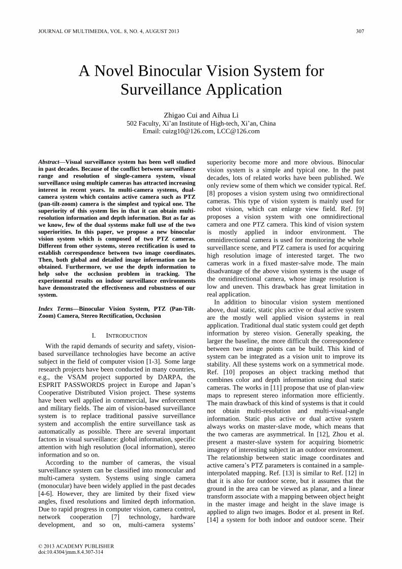
matched points, and the solid circle is the estimated zoom
center. The size of image is 320 240 .
Figure 1. Zoom center estimation result.
(a) (b)
(c)
Figure 2. PTZ camera calibration verification. The top two images are
the origin images captured from one of the two PTZ cameras. The
bottom image is the warping result according to our calibration
procedure. The PTZ parameters: (a) 1 [91.35, 11.23,2.00]PTZ and
(b) 2 [87.44, 9.23,9.00]PTZ .
B. Focal Length Estimation at Different Zoom Level
As shown in (2), the focal length is determined by the
zoom parameter. So we first estimate focal length at a
specified zoom value Z . Two images under the same
zoom value but different pan and tilt parameters are
captured. We assume the parameters of the two images
are ( , , )P T Z and ' '( , , )P T Z respectively. Then we use
SIFT feature points to establish correspondence between
the two images. For each of the matched points, we have
0
0
0
' ' '
0
0
0 ( , )
0 0 1
0
0 ( , )
0 0 1
i i
i i
f u
f v P T
f u
f v P T
x R X
x R X
(6)
As the extrinsic matrix R can be calculated by (3), and
the principal point 0 0( , )u v has been estimated in previous
content. So solving (6), we can obtain the estimation of
focal length for each of matched points. In order to
improve the robustness, we use all the matched points to
calculate the mean value as the final result of focal length.
After focal length has been estimated at several
discrete zoom levels, we choose a proper model to fit
these samples. In our study, we use (7) for approximation.
The four unknown parameters1p ,
2p ,3p and
4p can be
solved by using curve fitting tools.
2 4
1 3( )p Z p Z
f Z p e p e (7)
To verify the effectiveness of our calibration procedure,
we capture two images from the PTZ camera shown in
Fig. 2 (a) and (b) at different parameters. We use the
camera calibration result to warp image (b) to image (a)
with the same image coordinates. The result is shown in
Fig. 2 (c). The result shows that the warped image fits the
origin image well.
III. STEREO RECTIFICATION USING DUAL PTZ
CAMERAS
In traditional dual static system, the two cameras have
the same intrinsic parameters then the acquired images
are known as a rectified pair of stereo images. In these
images, corresponding points lie on a same horizontal
scan lines. So stereo matching algorithm can be directly
applied to calculate the disparity or depth information. In
dual PTZ camera system, it’s hard to directly estimate
disparity because that the two cameras may have different
extrinsic and intrinsic parameters especially the focal
length. Stereo rectification is a way to reduce the
searching scope in stereo matching from 2D to 1D. Many
stereo rectification methods have been proposed in the
past years [20-24]. In this paper, we use spherical
rectification method [23] to rectify images captured from
PTZ cameras. The reason for choosing this method lies in
that it can rectify images under arbitrary PTZ settings.
Meanwhile, disparity obtained by this method could
reflect the depth of the scene.
The main idea of spherical rectification method is
using two spherical surfaces as the bridge to achieve fast
and robust stereo rectification. It includes three steps: (1)
estimate a rotation matrix and establish spherical
coordinate system for each of the PTZ camera, the goal of
this step is to make sure the longitude components of
corresponding points be the same after coordinate
conversion from the camera coordinate to spherical
coordinate; (2) use PTZ camera model to map the image
plane to the unit spherical surface according to current
PTZ parameters; (3) the rectification is applied from the
sphere to rectified plane. This method is independent to
specific PTZ parameters, which is very convenient in
application. More details can be found in [23]. Fig. 3
shows an example of spherical rectification for two
images with quite different PTZ settings.
In our system, we use spherical rectification method to
establish correspondence between two image coordinates.
The conversion between origin image coordinate and
rectified image coordinate are frequently used in our
JOURNAL OF MULTIMEDIA, VOL. 8, NO. 4, AUGUST 2013 309
© 2013 ACADEMY PUBLISHER

system. So we summarize the conversion procedure as
follows.
(a) (b)
(c)
Figure 3. Example of spherical rectification: (a) and (b) are the origin
images captured from the two PTZ cameras with different parameters;
(c) is the rectification result. The PTZ parameters: (a)
1 [92.31, 10.65,5.00]PTZ and (b) 2 [93.28, 12.62,6.31]PTZ .
C. From Origin Image Coordinate ( , )x y to Rectified
Image Coordinate ( , )r rx y
Step1. Get camera coordinate X by the camera
model 1 1 x X R K , where is a scale factor
and T[ , ,1]x x y . R and K are the extrinsic matrix and
intrinsic matrix respectively, and can be obtained from
the calibration result (see (2) and (3)).
Step2. Use (8) to transform X to spherical coordinate
and obtain longitude and latitude coordinate ( , ) .
Where rR is rotation matrix which can transform the
camera coordinate to spherical coordinate. ( )r mX is the
m th component of vector rX .
arctan( (3), (2))
arccos( (1))
r
r
r r
r
X R X
X X
X
(8)
Step3. Adjust ( , ) to ( , ) by cot so that
the disparity can be preserved [23].
Step4. Calculate linear transformation parameters and
transform ( , ) to ( , )r rx y .
D. From Rectified Image Coordinate ( , )r rx y to Origin
Image Coordinate ( , )x y
Step1. Linear transform ( , )r rx y to ( , ) by using the
calculated transformation parameters.
Step2. Calculate the longitude and latitude coordinates
( , ) by 1tan ( 1/ ) .
Step3. Get corresponding camera coordinate X from
( , ) by (9). Where 1
r
R is the inverse matrix of rR .
1
(1) cos
(2) sin cos
(3) sin sin
r
r
r
r
r
X
X
X
X = R X
(9)
Step4. Get origin image coordinate ( , )x y from the
camera coordinate X by camera model (see (1)).
IV. THE PROPOSED SYSTEM
A. System Overview
Visual tracking
Need high
resolution
information?
Call object tracking using depth
information part
Call high resolution visual attention part
No
Need depth
information to
deal with
occlusion?
Yes
System initialization
Exit?
Tracking
database
Yes
Figure 4. System flow chart.
For our system, the hardware configuration is
composed of two PTZ cameras. The flow chart of our
system is shown in Fig. 4. Before main procedure starts,
an initialization procedure is needed. We first choose one
camera as the static view, and the other camera will be
served as the active camera. Then, in order to reduce the
computational complexity, some parameters can be pre-
calculated, i.e. camera calibration, stereo rectification
parameters, etc. The main procedure is composed of one
main thread and some other assistant threads. The main
thread is a common visual tracking loop in the static view,
including foreground extraction, objects detection and
tracking. The other assistant threads include high
resolution visual attention and object tracking using depth
information. Both of the two assistant threads need the
active camera’s cooperation. The visual tracking in static
view has been well studied in past decades. So we mainly
consider the two parts, i.e. the high resolution visual
attention and object tracking using depth information. In
high resolution visual attention part, two cameras work
on asymmetrical or master-salve module, and we use the
stereo rectification result and disparity to build the
relationship between two camera image coordinates.
Therefore, visual attention of multi-resolution can be
obtained. In object tracking using depth information part,
two cameras work on symmetrical mode, and we estimate
depth information on the rectified image fair. So that it
can be used for object tracking under the situation of
occlusion. In summary, the proposed system has the
310 JOURNAL OF MULTIMEDIA, VOL. 8, NO. 4, AUGUST 2013
© 2013 ACADEMY PUBLISHER
advantage of both traditional dual static and static-active
system.
B. High Resolution Visual Attention
In high resolution visual attention part, the two
cameras work on asymmetrical mode or master-salve
mode. The key technique of high resolution visual
attention is to calculate the new PTZ parameters of the
salve camera according to the master’s PTZ setting and
the selected region in master camera’s image. So the
slave camera could cover that region with a higher
resolution. Traditional methods mainly have two kinds of
control strategies: sampling-interpolation method and
mosaic image-based method. The first method constructs
a mapping from every pixel coordinates in static image to
PT parameters (such as [12]). This method has two
drawbacks. First, it assumes that the baseline is too small
comparing to the depth of the scene. So if the scene has
great change in depth, such as indoor environment, this
method may have large error. Second, if the master
camera’s view changes, the pre-configurations should be
re-done. The second method uses a mosaic image created
by snapshots of slave camera to estimate the relationship
between static master camera image plane and pan-tilt
controls of slave camera (such as [15, 16]). This method
relies on feature matches of master camera image and
salve camera mosaic image, and when the scene
appearance changes, the mosaic image should be updated.
To overcome the drawbacks of these methods, we
proposed another approach which directly uses rectified
image and disparity to calculate new PTZ parameters.
Rectified image pair and disparity map is a bridge
between the two images coordinates, so that two image
coordinates can be mapped from one to another by
rectification mapping added a disparity translation. We
denote 1I and
2I as the master camera image and salve
camera image respectively, 1 1 1( , , )P T Z and
2 2 2( , , )P T Z as
the parameters of the master and salve camera. We
denote as the selected region in master camera’s image.
The procedure of our method is listed as follows:
Step1. Use spherical rectification method to rectify 1I
and 2I . We denote the rectified images as 1rI and 2rI .
Step2. Find the center 1c of the region in image 1I .
Then calculate 1c ’s corresponding location 1rc in rectified
image 1rI (see detailed procedure in section III).
Step3. Use graph cuts based stereo matching algorithm
[25] to estimate the mean disparity d at 1rc . Denote
2rc as the corresponding point in rectified image 2rI of the
salve camera image 2I , where T
2 1 [ ,0]r rc c d .
Step4. Calculate 2c in 2I from corresponding 2rc in
2rI (see detailed procedure in section III).
Step5. Calculate new PTZ parameters ' ' '
2 2 2( , , )P T Z given point 2c and the origin PTZ parameters
2 2 2( , , )P T Z of the slave camera. This step can be divided
into two parts, the PT parameters and Z parameter
calculation. Let 2 ( , )s sc x y , and the principal point
is0 0( , )u v . According to (7) and zoom value of slave
camera2Z , we can calculate the focal length f . Then the
absolute angles of pan and tilt parameters are
0
0
arctan arctan
arctan arctan
ss
ss
x uxP
f f
y vyT
f f
(10)
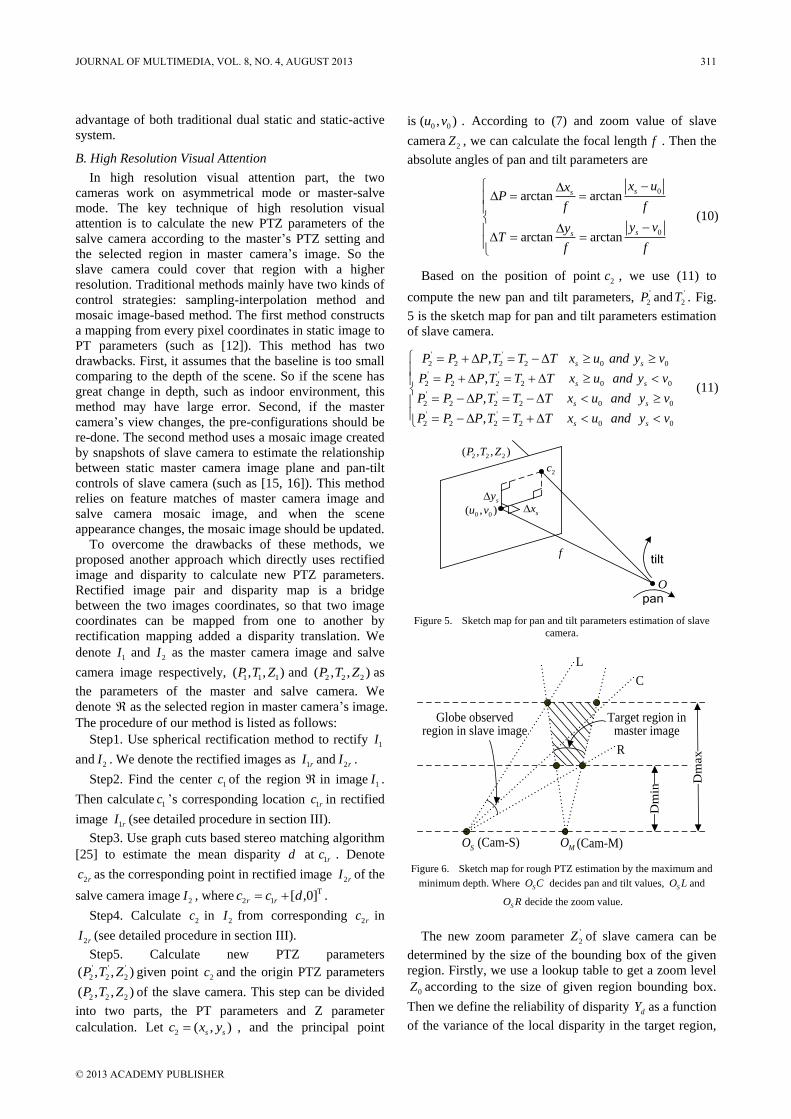
Based on the position of point 2c , we use (11) to
compute the new pan and tilt parameters, '
2P and '
2T . Fig.
5 is the sketch map for pan and tilt parameters estimation
of slave camera.
' '
2 2 2 2 0 0
' '
2 2 2 2 0 0
' '
2 2 2 2 0 0
' '
2 2 2 2 0 0
,
,
,
,
s s
s s
s s
s s
P P P T T T x u and y v
P P P T T T x u and y v
P P P T T T x u and y v
P P P T T T x u and y v
(11)
O
0 0( , )u v
2c
sxsy
ftilt
pan
2 2 2( , , )P T Z
Figure 5. Sketch map for pan and tilt parameters estimation of slave
camera.
Dm
ax
MOSO (Cam-S) (Cam-M)
Target region in master image
Dm
in
Globe observed region in slave image
L
R
C
Figure 6. Sketch map for rough PTZ estimation by the maximum and
minimum depth. Where SO C decides pan and tilt values, SO L and
SO R decide the zoom value.
The new zoom parameter '
2Z of slave camera can be
determined by the size of the bounding box of the given
region. Firstly, we use a lookup table to get a zoom level
0Z according to the size of given region bounding box.
Then we define the reliability of disparity dY as a function
of the variance of the local disparity in the target region,
JOURNAL OF MULTIMEDIA, VOL. 8, NO. 4, AUGUST 2013 311
© 2013 ACADEMY PUBLISHER

which satisfies [0,1]dY . We use dY as a weight, so the
final zoom parameter '
2 0( , )dZ Z Z R (in our
system, '
2 0 (0.7 0.3 )dZ Z R ). That’s means if the
reliability of disparity is low, we lower down the zoom
level. Otherwise, we give a higher zoom level.
If the target region is not visible in the salve camera
image, we can’t estimate the disparity translation on the
two rectified images. In this situation, we first estimate
rough PTZ parameters by the maximum maxD and
minimum minD depth, see Fig. 6. Then after the salve
camera moves to the rough PTZ position, we use
procedure described above to estimate precise PTZ
parameters.
C. Object Tracking Using Depth Information
Depth information is very useful in visual surveillance.
And the depth information can improve object
segmentation and tracking in case of multiple occluding
objects. All work before use dual static cameras. In this
paper, the depth information is introduced to our dual
PTZ camera system. In this part, the two cameras work
on symmetrical mode. As we know, when occlusion
happens, part of the occluded object is invisible. So the
occluding and occluded objects have different depth.
Although the depth information estimated by vision
approach is always less credible because of the
uncertainty of stereo matching, in our system, this coarse
depth information is adequate in that we only need to
give a depth order of occluded objects.
In our system, we implement a tracking loop in static
camera procedure which works well with no occlusion.
Under occlusion situation, the tracking procedure will
send a message to active camera. Then two cameras can
calculate depth information by spherical rectification and
stereo matching. In order to reduce computational work,
we only estimate the depth information in foreground
area. The prior knowledge of segmentation and tracking
comes from the tracking history which can be obtained
from the tracking database, see Fig. 4. The prior
knowledge includes the number of objects in the
occlusion area and previous location of each object. Then
we classify each foreground pixel into objects according
to location and depth information of each pixel. To
improve the robustness of our system, we also use a post
process of validation. The validation considers the
proportion of segmentation region. If the region is too
small, the segmentation is invalid. For valid segmentation,
the timestamp, segmentation region and depth
information will be updated into tracking database.
We summarize the procedure as follows:
Step1. Use spherical rectification method to rectify
images of the two cameras.
Step2. Estimate the disparity map in the foreground
region by using graph cuts based stereo matching
algorithm [25].
Step3. Collect prior knowledge from the tracking
database, such as the objects number in occlusion area
n and the previous location of each object.
Step4. Classify all the foreground pixels into n classes
according its disparity and coordinates.
Step5. Calculate the property of each new class, such
as area, centre and depth.
Step6. Validate the segmentation result. We consider
the proportion of segmentation area, that a too small
value suggests an invalid segmentation.
Step7. Update new class centre and depth into tracking
database for valid segmentation result.
V. EXPERIMENTAL RESULTS
The validity of our system has been evaluated on an
indoor environment. The system runs on one computer
with Intel 3.0G CPU and 1.5G memory. Two SONY EVI
D70 cameras were placed on the top window, at about 1.2
meters far from each other. Images from both cameras
were taken at 320 240 pixels of resolution.
(a)
(b)
Figure 7. Results of high resolution visual attention. The top two
images of (a) and (b) are the origin images of the master and salve
camera respectively. The bottom images of (a) and (b) are salve camera
images after moving to newly estimated values. (a) The selected object
is visible in the salve camera image; (b) The selected object is invisible
in the salve camera image.
Firstly, we present the experimental results of high
resolution visual attention. The experiments try to explain
the robust result in two cases of salve camera’s state: the
selected object is visible in the salve camera image and
the selected object is invisible in the salve camera image.
Fig. 7 shows the results under these two conditions. In the
initialization, the target region is selected in master
camera image highlighted by white box. The parameters
312 JOURNAL OF MULTIMEDIA, VOL. 8, NO. 4, AUGUST 2013
© 2013 ACADEMY PUBLISHER
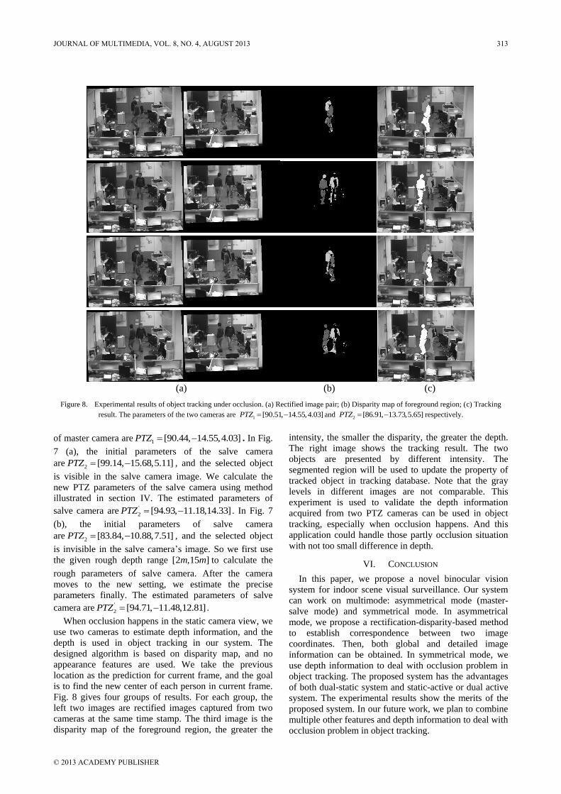
(a) (b) (c)
Figure 8. Experimental results of object tracking under occlusion. (a) Rectified image pair; (b) Disparity map of foreground region; (c) Tracking
result. The parameters of the two cameras are 1 [90.51, 14.55,4.03]PTZ and 2 [86.91, 13.73,5.65]PTZ respectively.
of master camera are 1 [90.44, 14.55,4.03]PTZ . In Fig.
7 (a), the initial parameters of the salve camera
are 2 [99.14, 15.68,5.11]PTZ , and the selected object
is visible in the salve camera image. We calculate the
new PTZ parameters of the salve camera using method
illustrated in section IV. The estimated parameters of
salve camera are '
2 [94.93, 11.18,14.33]PTZ . In Fig. 7
(b), the initial parameters of salve camera
are 2 [83.84, 10.88,7.51]PTZ , and the selected object
is invisible in the salve camera’s image. So we first use
the given rough depth range [2 ,15 ]m m to calculate the
rough parameters of salve camera. After the camera
moves to the new setting, we estimate the precise
parameters finally. The estimated parameters of salve
camera are '
2 [94.71, 11.48,12.81]PTZ .
When occlusion happens in the static camera view, we
use two cameras to estimate depth information, and the
depth is used in object tracking in our system. The
designed algorithm is based on disparity map, and no
appearance features are used. We take the previous
location as the prediction for current frame, and the goal
is to find the new center of each person in current frame.
Fig. 8 gives four groups of results. For each group, the
left two images are rectified images captured from two
cameras at the same time stamp. The third image is the
disparity map of the foreground region, the greater the
intensity, the smaller the disparity, the greater the depth.
The right image shows the tracking result. The two
objects are presented by different intensity. The
segmented region will be used to update the property of
tracked object in tracking database. Note that the gray
levels in different images are not comparable. This
experiment is used to validate the depth information
acquired from two PTZ cameras can be used in object
tracking, especially when occlusion happens. And this
application could handle those partly occlusion situation
with not too small difference in depth.
VI. CONCLUSION
In this paper, we propose a novel binocular vision
system for indoor scene visual surveillance. Our system
can work on multimode: asymmetrical mode (master-
salve mode) and symmetrical mode. In asymmetrical
mode, we propose a rectification-disparity-based method
to establish correspondence between two image
coordinates. Then, both global and detailed image
information can be obtained. In symmetrical mode, we
use depth information to deal with occlusion problem in
object tracking. The proposed system has the advantages
of both dual-static system and static-active or dual active
system. The experimental results show the merits of the
proposed system. In our future work, we plan to combine
multiple other features and depth information to deal with
occlusion problem in object tracking.
JOURNAL OF MULTIMEDIA, VOL. 8, NO. 4, AUGUST 2013 313
© 2013 ACADEMY PUBLISHER

REFERENCES
[1] I. Ahmad, Z. He, M. Liao, F. Pereira, and M.-T. Sun,
“Special issue on video surveillance”, IEEE Transactions
on Circuits and Systems for Video Technology, vol. 18, pp.
1001-1005, 2008.
[2] T. Gao, P. Wang, C Wang, and Z. Yao, “Feature particles
tracking for moving objects”, Journal of Multimedia, vol. 7,
no.6, pp. 408-414, 2012.
[3] D. Kieran, J. Weir, and W. Yan, “A framework for an
event driven video surveillance system”, Journal of
Multimedia, vol. 6, no.1, pp. 3-13, 2012.
[4] C. Wren, A. Azarbayejani, T. Darrell, and A. Pentland,
“Pfinder: real-time tracking of the human body”, IEEE
Transactions on Pattern Analysis and Machine Intelligence,
vol. 19, pp. 780-785, 1997.
[5] C. Pai, H. Tyan, Y. Liang, H. Liao and S. Chen,
“Pedestrian detection and tracking at crossroads”, Pattern
Recognition, vol. 37, pp.1025-1034, 2004.
[6] I. Haritaoglu, D. Harwood, and L.S. Davis, “W4: real-time
surveillance of people and their activities”, IEEE
Transactions on Pattern Analysis and Machine Intelligence,
vol. 22, pp. 809-830, 2000.
[7] X Zhu, Y Gui, and H Xu, “Enhanced differentiated
surveillance for static and random mobile sensor networks”,
Journal of Networks, vol. 6, no 10, pp. 1483-1490, 2011.
[8] G. Adorni, S. Cagnoni, M. Mordonini, and A. Sgorbissa,
“Omnidirectional stereo systems for robot navigation”, in
Proc. IEEE Workshop on Omnidirectional Vision and
Camera Networks, pp.79-89, 2003.
[9] C. Chen, Y. Yao, D. Page, B. Abidi, A. Koschan, and
M.Abidi, “Heterogeneous fusion of omnidirectional and
PTZ cameras for multiple object tracking”, IEEE
Transactions on Circuits and Systems for Video
Technology, vol. 18, no.8, pp. 1052-1063, 2008.
[10] R. Munoz-Salinas, E. Aguirre, M. Garcia-Silvestre, and A.
Gonzalez, “A multiple object tracking approach that
combines colour and depth information using a confidence
measure”, Pattern Recognition Letters, vol. 29, pp. 1504-
1514, 2008.
[11] R. Munoz-Salinas, “A Bayesian plan-view map based
approach for multiple-person detection and tracking”,
Pattern Recognition, vol. 41, pp. 3665-3676, 2008.
[12] X.H. Zhou, R.T. Collins, T. Kanade, and P. Metes, “A
master-slave system to acquire biometric imagery of
humans at a distance”, ACM SIGMM International
Workshop on Video Surveillance, pp. 113-120, 2003.
[13] A.W. Senior, A. Hampapur, and M. Lu, “Acquiring multi-
scale images by pan-tilt-zoom control and automatic multi-
camera calibration”, IEEE Workshop on Application on
Computer Vision, pp. 433-438, 2005.
[14] R. Bodor, R. Morlok, and N. Papanikolopoulos, “Dual-
camera system for multi-level activity recognition,” Proc.
of the IEEE/RJS International Conference on Intelligent
Robots and Systems, vol. 1, pp. 643-648, 2004.
[15] Y. Li, L. Song, and J. Wang, “Automatic weak calibration
of master-salve surveillance system based on mosaic
image”, International Conference on Pattern Recognition,
pp. 1824-1827, 2010.
[16] A.D. Bimbo, F. Dini, G. Lisanti, and F. Pernici,
“Exploiting distinctive visual landmark maps in pan-tilt-
zoom camera networks”, Computer Vision and Image
Understanding, vol. 114, pp. 611-623, 2010.
[17] S.N. Sinha and M. Pollefeys, “Pan-tilt-zoom camera
calibration and high-resolution mosaic generation”,
Computer Vision and Image Understanding, vol. 103, pp.
170-183, 2006.
[18] D.G. Lowe, “Distinctive image features from scale-
invariant keypoints”, International Journal of Computer
Vision, vol. 60, pp. 91-101, 2004.
[19] M.A. Fischler, R.C. Bolles, “Random sample consensus: a
paradigm for model fitting with applications to image
analysis and automated cartography”, Communications of
ACM, vol. 24, pp. 381-395, 1981.
[20] M. Pollefeys and S.N. Sinha, “Iso-disparity surfaces for
general stereo configurations”, European Conference on
Computer Vision, vol. 3, pp.509-520, 2004.
[21] C.T. Loop and Z. Zhang, “Computing rectifying
homographies for stereo vision”, IEEE Conference on
Computer Vision and Pattern Recognition, pp.1125-1131,
1999.
[22] R.I. Hartley, “Theory and practice projective rectification”,
International Journal of Computer Vision, vol. 35, pp.
115-127, 1999.
[23] D. Wan, J. Zhou, and D. Zhang, “A spherical rectification
for dual-PTZ camera system”, IEEE International
Conference on Acoustics, Speech and Signal Processing,
vol. 1, pp. 777-780, 2007.
[24] S. Kumar, C. Micheloni, C. Piciarelli, and G.L. Foresti,
“Stereo rectification of uncalibrated and heterogeneous
images”, Pattern Recognition Letters, vol. 31, pp. 1445-
1452, 2010.
[25] Y. Boykov, O. Veksler, and R. Zabin, “Fast approximate
energy minimization via graph cuts”, IEEE Transactions
on Pattern Analysis and Machine Intelligence, vol. 23, pp.
1222-1239, 2001.
Zhigao Cui born in 1984, Hengshui, Hebei province, China. He
is currently a doctor of Xi’an Institute of High-tech of China.
His research interests include binocular vision surveillance and
image processing.
Aihua Li was born in 1966. Professor and Ph.D. supervisor in
Xi’an Institute of High-tech of China. His main research
interests include pattern recognition, signal processing and
computer vision.
314 JOURNAL OF MULTIMEDIA, VOL. 8, NO. 4, AUGUST 2013
© 2013 ACADEMY PUBLISHER