
A NON-LINEAR FINITE ELEMENT APPROACH FOR …alexandria.tue.nl/repository/freearticles/605480.pdfA...
15
hr. J. Solids Slrucfures Vol. 30, No. 9, pp. 1239-1253, 1993 002&7683/93 S6.00+ .30 Printed in Great Britain 0 I993 Pergamon Press Ltd A NON-LINEAR FINITE ELEMENT APPROACH FOR THE ANALYSIS OF MODE-I FREE EDGE DELAMINATION IN COMPOSITES J. C. J. SCHELLEKENS Delft University of Technology, Department of Civil Engineering, P.O. Box 5048, 2600 GA Delft, The Netherlands and R. DE BORST Delft University of Technology, Department of Civil Engineering/TN0 Building and Construction Research, P.O. Box 5048, 2600 GA Delft, The Netherlands (Received 5 March 1992 ; in revisedform 5 October 1992) Abstract-Free edge delamination of uniaxially stressed layered specimens is simulated using non- linear finite element analysis. Generalized plane strain elements and interface elements have been developed for this purpose. Thermal and hygroscopic effects have been taken into account for the modelling of the plys, and a mode-1 fracture model which incorporates strain softening has been used for the interface behaviour. The out-of-plane loading is controlled via an indirect displacement control technique, which permits tracing the entire loading history. Using non-linear finite element analysis free edge delamination in different graphite/epoxy laminates is examined. The numerical results are in good agreement with experimental evidence and do not suffer from spurious mesh dependence. Also the effects of laminate thickness (size effect) can be described properly. 1. INTRODUCTION In recent years the application of composite materials in structural components has become increasingly popular. Especially in aircraft structures, composites are preferred to con- ventional materials because of their high strength/stiffness versus weight ratios. However, the relatively limited existing predictive capabilities for the growth of delamination in laminated composites have delimited using the full potential of these materials. Due to the varying fibre orientations and the anisotropy of the material, each ply of a laminated composite behaves independently of the other plys. Large edge stresses are then necessary to preserve compatibility of deformations. Together with matrix cracks transverse stresses near the free edge are primarily responsible for the initiation of delamination. To gain more insight in the complex phenomenon of delamination, we need procedures that give us accurate predictions of delamination onset and growth. In this contribution we shall focus on free edge delamination in uniaxially loaded laminates, which has been the subject of much research since the early 1970s (Crossman and Wang, 1982 ; Kim and Soni, 1984 ; O’Brien, 1982, 1985 ; Pagano, 1974 ; Pagan0 and Soni, 1989 ; Pipes and Pagano, 1970 ; Wang et al., 1985; Wang, 1989). Although finite element analysis combined with stress-based fracture criteria like the one proposed by Tsai and Wu (197 1) are often used to predict the failure of a composite structure, it is widely recognized that the results of such a procedure should be regarded with caution because they strongly depend upon the finite element discretization. To avoid this problem of mesh dependence Kim and Soni (1984) have used an average stress criterion. The introduction of the ply thickness as a length scale, which results in a so-called non- local model, is essential in their approach. However, delamination does not necessarily progress at the location where the stresses have the maximum values, but grows at the interface where the energy release rate exceeds the fracture toughness of the material. This casts doubts on failure predictions that are purely based on stress criteria. In view of the above arguments a crack-extension or crack-closure method seems more appropriate in delamination analysis (O’Brien, 1982, 1985; Schellekens and de Borst, 1991a ; Wang et al., 1985 ; Wang, 1989). Since these procedures calculate the energy release rate from nodal forces and displacements rather than from stresses and strains, the results 1239
Transcript of A NON-LINEAR FINITE ELEMENT APPROACH FOR …alexandria.tue.nl/repository/freearticles/605480.pdfA...

hr. J. Solids Slrucfures Vol. 30, No. 9, pp. 1239-1253, 1993 002&7683/93 S6.00+ .30
Printed in Great Britain 0 I993 Pergamon Press Ltd
A NON-LINEAR FINITE ELEMENT APPROACH FOR THE ANALYSIS OF MODE-I FREE EDGE
DELAMINATION IN COMPOSITES
J. C. J. SCHELLEKENS Delft University of Technology, Department of Civil Engineering, P.O. Box 5048,
2600 GA Delft, The Netherlands
and
R. DE BORST Delft University of Technology, Department of Civil Engineering/TN0 Building and
Construction Research, P.O. Box 5048, 2600 GA Delft, The Netherlands
(Received 5 March 1992 ; in revisedform 5 October 1992)
Abstract-Free edge delamination of uniaxially stressed layered specimens is simulated using non- linear finite element analysis. Generalized plane strain elements and interface elements have been developed for this purpose. Thermal and hygroscopic effects have been taken into account for the modelling of the plys, and a mode-1 fracture model which incorporates strain softening has been used for the interface behaviour. The out-of-plane loading is controlled via an indirect displacement control technique, which permits tracing the entire loading history. Using non-linear finite element analysis free edge delamination in different graphite/epoxy laminates is examined. The numerical results are in good agreement with experimental evidence and do not suffer from spurious mesh dependence. Also the effects of laminate thickness (size effect) can be described properly.
1. INTRODUCTION
In recent years the application of composite materials in structural components has become increasingly popular. Especially in aircraft structures, composites are preferred to con- ventional materials because of their high strength/stiffness versus weight ratios. However, the relatively limited existing predictive capabilities for the growth of delamination in laminated composites have delimited using the full potential of these materials.
Due to the varying fibre orientations and the anisotropy of the material, each ply of a laminated composite behaves independently of the other plys. Large edge stresses are then necessary to preserve compatibility of deformations. Together with matrix cracks transverse stresses near the free edge are primarily responsible for the initiation of delamination. To gain more insight in the complex phenomenon of delamination, we need procedures that give us accurate predictions of delamination onset and growth. In this contribution we shall focus on free edge delamination in uniaxially loaded laminates, which has been the subject of much research since the early 1970s (Crossman and Wang, 1982 ; Kim and Soni, 1984 ; O’Brien, 1982, 1985 ; Pagano, 1974 ; Pagan0 and Soni, 1989 ; Pipes and Pagano, 1970 ; Wang et al., 1985; Wang, 1989).
Although finite element analysis combined with stress-based fracture criteria like the one proposed by Tsai and Wu (197 1) are often used to predict the failure of a composite structure, it is widely recognized that the results of such a procedure should be regarded with caution because they strongly depend upon the finite element discretization. To avoid this problem of mesh dependence Kim and Soni (1984) have used an average stress criterion. The introduction of the ply thickness as a length scale, which results in a so-called non- local model, is essential in their approach. However, delamination does not necessarily progress at the location where the stresses have the maximum values, but grows at the interface where the energy release rate exceeds the fracture toughness of the material. This casts doubts on failure predictions that are purely based on stress criteria.
In view of the above arguments a crack-extension or crack-closure method seems more appropriate in delamination analysis (O’Brien, 1982, 1985; Schellekens and de Borst, 1991a ; Wang et al., 1985 ; Wang, 1989). Since these procedures calculate the energy release rate from nodal forces and displacements rather than from stresses and strains, the results
1239

1240 J. C. J. SCHELLEKENS and R. DE BORS~
(a) cubic line interface (b) nodal displacements
(c) tractions and relative
displacements
Fig. 1. Cubic line interface element with nodal degrees-of-freedom.
are mesh independent, although a certain level of mesh refinement is necessary. A dis- advantage of these linear fracture mechanics options is that, before we can determine the interface that is the most critical, the energy release rate has to be calculated at each location where delamination may initiate. This can become an expensive exercise, especially for large structures.
In the proposed procedure generalized plane-strain elements with cubic interpolations are used to model the plys of the laminate. A geometrically non-linear formulation is developed for these elements, which have three translational degrees-of-freedom per node, so that the warping of the cross-section can be described. To properly account for the stresses that are induced during the manufacturing process thermal and hygroscopic effects are included in the constitutive fo~ulation for the pfys. The plys are connected by eight- noded line interface elements which have the ability to model the geometric discontinuity that arises during the delamination process. Initially, these interface elements have a zero thickness with four pairs of overlapping nodes (Fig. 1). After initiation of delamination the nodes of a pair are released.
Initiation of delamination in the ply interface occurs when the stress normal to the plys exceeds the strength ft of the ply interface. For this reason, initiation of delamination suffers to a certain extent from mesh sensitivity. That is, for smaller elements the high stress gradients are captured more accurately and higher peak stresses are computed, which cause violation of the stress-based delamination initiation criterion.
The situation is different with respect to delamination propagation. The stress-strain behaviour after the onset of delamination is governed by a softening type of response as shown in Fig. 2. The quintessence of the approach is that the surface under the softening curve is equal to the critical energy release rate G, in the ply interface of the laminate. This ensures on one hand a correct energy release during delamination propagation, so that propagation is independent of the mesh refinement, and on the other hand it results in a proper description of the size effect, i.e. a thicker laminate fails at a lower ultimate strain (more brittle).
Fig. 2. Traction-relative displacement relations for interface elements.
Free edge delamination 1241
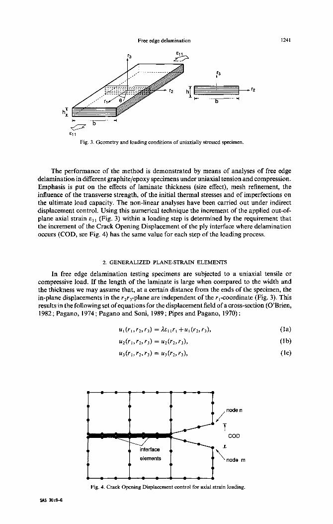
Fig. 3. Geometry and loading conditions of uniaxially stressed specimen.
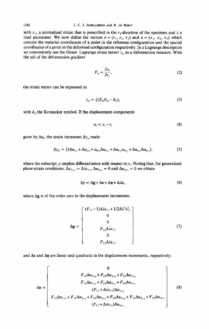
The performance of the method is demonstrated by means of analyses of free edge delamination in different graphite/epoxy specimens under uniaxial tension and compression. Emphasis is put on the effects of laminate thickness (size effect), mesh refinement, the influence of the transverse strength, of the initial thermal stresses and of imperfections on the ultimate load capacity. The non-linear analyses have been carried out under indirect displacement control. Using this numerical technique the increment of the applied out-of- plane axial strain E, , (Fig. 3) within a loading step is determined by the requirement that the increment of the Crack Opening Displacement of the ply interface where delamination occurs (COD, see Fig. 4) has the same value for each step of the loading process.
2. GENERALIZED PLANE-STRAIN ELEMENTS
In free edge delamination testing specimens are subjected to a uniaxial tensile or compressive load. If the length of the laminate is large when compared to the width and the thickness we may assume that, at a certain distance from the ends of the specimen, the in-plane displacements in the r,r,-plane are independent of the I ,-coordinate (Fig. 3). This results in the following set of equations for the displacement field of a cross-section (O’Brien, 1982 ; Pagano, 1974 ; Pagan0 and Soni, 1989 ; Pipes and Pagano, 1970) :
/
node n
f
1 COD
\ node m
l_=!==Lzl Fig. 4. Crack Opening Displacement control for axial strain loading.
SAS 30:9-G
1242 J. C. J. SCHELLEKENS and R. DE BORST
with E, , a normalized strain that is prescribed in the r,-direction of the specimen and A a load parameter. We now define the vectors r = (r ,, r2, r3) and x = (x,, x2, x3) which contain the material coordinates of a point in the reference configuration and the spatial coordinates of a point in the deformed configuration respectively. In a Lagrange description we conveniently use the Green-Lagrange strain tensor yii as a deformation measure. With the aid of the deformation gradient
F..=aX’ 1’ arj'
the strain tensor can be expressed as
with 6, the Kronecker symbol. If the displacement components
Ui = Xi-ri
(3)
(4)
grow by Aui, the strain increment Arij reads :
AYij = f (Aui,r, + Auj,r, + uk,r,Auk.rj + A~k,r~uk,~~ + Au~,~~Au~,,), (5)
where the subscript ,ri implies differentiation with respect to ri. Noting that, for generalized plane-strain conditions, Au,,,, = Ale, ,, AU*.,, = 0 and AUK,,, = 0 we obtain
Ay = Ag+Ae+A~+A~,,
where Ag is of the order zero in the displacement increments,
Ae =
Ag =
(F,, - l)Aclle,, + 1/2A1%:,
0
0
FIzAAE~,
0
F,,Als,,
,
and Ae and 89 are linear and quadratic in the displacement increments, respectively :
(6)
(7)
(8)

and
Aq =
c
Free edge delamination 1243
0
l/2((A~,,,,)2+(A~~.~~)2+(A~~,~~)2)
1/2((A~,,~,)*+(A~2,r,)*+(A~3.r,)*)
0
Au,,r,Au,,r, +Au2,r2Au2.r, +Au~r,Au3,r,
0
(9)
(10)
The contribution Ah, is due to the applied strain loading :
Extension of eqn (6) to include hygrothermal effects yields :
Ay = Ag+Ae+Aq+AJs,+ATia+AC$, (11)
where ATi and ACi are the incremental changes in temperature and moisture content in the
current loading step, say i, and a = (~1, r, az2, a33, ~1~2, a23, a3d and b = (PII, fi2*, b33, B12,
jl23, B3 ,) contain the thermal and hygroscopic expansion coefficients, respectively. Assuming that there are no other non-linear effects in the plys the stress increment at iteration j is then given by
Aaj = Dp(Agj + Aej + Aqj + AIjsl+ AT+ + ACJ), (12)
with DP the elastic stress-strain matrix for the plys and AAj the value of the incremental load parameter at iteration j. Subtracting the relation for the stresses at the end of iteration j- 1 from eqn (12) results in
aj = aj- 1 + Dp(dgj + dej + dqj + dJjs[), (13)
where the d-symbol denotes the iterative change of a quantity from iteration j- 1 to iteration j.
For the derivation of the element stiffness matrix and the element load vector, the principle of virtual work is utilized. Because of the absence of external loadings in the r2r3- plane the equilibrium equation that refers to the undeformed reference configuration reads :
(14)
where V,, denotes the volume of the body in the undeformed state. The variation of the Green-Lagrange strain 6yj = 6yj_ I + 6(dyj) is given by
67, = 6(&j) + S(dej) + d(tij), (15)
since the variation of the strain at the end of the previous iteration vanishes, 6yj_, = 0, and

1244 J. C. J. SCHELLEKENS and R. DE BOR~T
since ATi and AC are constant during the loading/time step. We now substitute eqns (13) and (15) in the virtual work expression and linearize in order to apply Newton’s method for the solution of the set of non-linear equations. Transferring the terms that are of the order zero in the displacement increments to the right-hand side gives :
s 6(dej)TD,dej d Vo +
s 6(dqj) ‘(aj _ I+ D,dgj + djD+,) d Vo
Vll VO
=- s s(dej)‘(Uj_ 1 +Dpdgj+dljD,el) dVo* (16) VO
In the following we shall describe the discretization of the virtual work equation. The linear part dej of the incremental strain vector is related to the incremental nodal displace- ment vector da = (dui,daf, . . . ,dd(, da:, . . . , dd;, da:, . . . , dd;) through
dej = B,daj.
BL denotes the linear strain displacement matrix, which is equal to [cf. eqn (8)]
(17)
BL =
0 0 0
f'12n.r~ F22n,r2 F32n,r,
f'13n,rl F23%, F33n,r,
(FI 1 +dlj~~ I)n,r2 0 0
F, 3n,12+ F12n,,, F23n,r2 +F22n.,, F33n.rz + F32°~~x
(FI I+ dAj& 1 I )%, 0 0
In eqn (18) we have used the notation
n,,, = WI,,,, N2,+, . . . , NJ,
W-3)
(19)
with n being the number of element nodes and N,, . . . , N, the interpolation polynomials. With the aid of eqn (17) the first term of eqn (16) can be written as
s 6(dej)TD,dej d ?‘o = 6(daj)’ s
BzD,oBL d I’0 daj. VII VII
We next introduce the non-linear strain displacement matrix BNL :
BNL =
0 0 o- 0 0 0
0 0 0
4* 0 0
0 a,,* 0
0 0 a.% a .I3 0 0
0 a,+ 0
0 0 ?r3 _
(20)
(21)
with a,rj = alari. Then, the second term in the left-hand side of the virtual work expression

Free edge delamination 1245
becomes
s G(dt/i)T(aj_ I+ Dpdgj + dAjD+/) d Vo = G(daj)T s
B&L@ + E)BNL d Vodaj. (22) VII VO
The 9 x 9 matrices E and E are equal to :
and
GW
Wb)
with Qij the Second Piola-Kirchhoff stress tensor and os,ij given by
a, = Dp(dg+dh,),
uS = ~“~,*~~~g9,22~~g,~3,~~,,2,~~,23,~~,~,]T. (24)
Substitution of eqns (17) and (22) into eqn (16), and requiring that the virtual work principle holds for any virtual displacement increment yields
K,da, = - I
BTUj_ 1 dV,-d;lj f
B:Dg, d V,, - VO VO s
RZDpdgj d Vo 3 (25) VO
where
Kj = s
B:DpBL d Vo + s
BiL(X+E)BNL dV,. VO VO
(26)
3. INDIRECT DISPLACEMENT CONTROL FOR STRAIN LOADING
A major drawback of load-controlled calculations is the fact that no limit points can be passed. Riks (1979) has developed an arc-length method to overcome this limitation. In this method the incremental load factor is constrained by the norm of the incremental displacement vector. Although the arc-length control method has proven to be fairly successful, it has been reported to fail in the case of highly localized failure modes. It was suggested by de Borst (1987) that the displacement norm should in these cases be calculated by considering a displacement vector that contains only the dominant degrees-of-freedom.
In conventional strain loading the incremental nodal displacement vector daj for iteration j in a loading step is determined from eqn (25). If we define q as a normalized external load vector :
q= - f
B:D& d Vo, (27) VO
and the internal force vector p as :
pi-1 = - s BTUj_1 dVo+Alj-i s
R;D,e, d V, - VO VO s
Bl D&j d VO 3 (28) VO

1246 J. C. J. SCHELLEKENS and R. DE BORST
then eqn (25) can be rephrased as :
Kjdaj = Aljq + pi- 1) w
since the iterative change dAj of the load parameter equals d;lj = ALj- A;lj_, . In an arc- length modification of strain loading this process can be represented by the following set of equations [e.g. de Borst (1987)] :
da; = K;‘pj_ ,, (30)
day = Kj ‘q,
da, = da; + d;ljda$‘.
(31)
(32)
The incremental displacement vector daj is determined on the basis of the requirement that the Crack Opening Displacement (COD) of the interface between the two plys where determination occurs should have the same value for each iteration (Fig. 4) :
d(COD) = O*dq--dq = 0. (33)
In this relation 4 is the change in displacement in the thickness direction of the laminate of node n from iteration j- 1 to j.
Substituting eqn (32) in eqn (33) yields the value for the incremental load parameter :
(34)
The total incremental displacement vector from which the strains and stresses are calculated is then obtained from
Aaj = Aaj- 1 +daj. (35)
4. FORMULATION OF INTERFACE ELEMENTS AND DISCRETE CRACKING
The individual plys in the laminate are connected by interface elements (Schellekens and de Borst, 1991a, b, 1992, Fig. 1). In the elastic stage of the calculation no additional deformations are allowed in the finite element model because of the introduction of the interface elements in the finite element model. Therefore a sufficiently high dummy stiffness has to be supplied. With the differential operator matrix L and the interpolation matrix H defined as [e.g. Rots (1988) and Schellekens and de Borst (1993)] :
[
-1 +l 0 0 0 0
L=
0 0 -1 +l 0 0
0 0 0 0 -1 +l 1 and
r nOOOO0 1 10 n 0 0 0 01
OOnOOO
H’OOOnOO’
OOOOnO
(36)
(37)
10 0 0 0 0 nJ

Free edge delamination
with n the interpolation polynomial vector and the nodal displacement vector
1247
a = (a:, a:, . . . , d;, a:, a:, . . . , d2, at, a:, . . . , al), (38)
the relative displacement vector v is related to the nodal displacements through
v = LHa. (39
If we denote the tangential stiffness matrix by D,, the tractions t = (t,, t,, t,) are obtained from
t = D,v. (40)
For a line interface element in a generalized plane-strain situation the tangential element stiffness matrix then reads
s <=+I
K= BTD,B detJ dt, (41) {=-I
in which r is the iso-parametric coordinate and detJ is the determinant of the Jacobian matrix :
detJ = [(ar,/ay)*+(ar3/ay)*]“*.
Once the elastic limit in an integration point of the interface element is exceeded the traction-relative displacement relation D1 becomes non-linear and is determined by a discrete fracture model. In the present model delamination is initiated purely in mode-I, that is when the traction t,, normal to the plys exceeds the transverse tensile strength fi of the ply interface in the composite laminate. The traction and stiffness in mode-1 delamination are then gradually reduced to zero (c$ Fig. 2 for a linear softening type of post-cracking response). As stated in the Introduction the surface under the softening curve is equal to the critical energy release rate G, in the ply interface of the composite material. When the fracture energy has been released completely, there is an internal stress-free geometrical discontinuity.
For the derivation of the non-linear stiffness relation we shall use a decomposed approach (Rots, 1988) in which the total incremental relative displacement vector in iter- ation j consists of an elastic part A$’ and an inelastic part which is equal to the crack relative displacement A$. In the crack model the incremental tractions Atj for the intact material are given by
Atj = D,A$, (42)
with Avy being the incremental elastic relative displacement vector. The incremental crack- relative displacements Avy are related to the incremental tractions according to
At. = DrAvV J I, (43)
where Dy’ is the crack stiffness matrix which is dependent on the mode-1 post crack relation. The total incremental relative displacement is written as
Avj = A$ + A$=. (44)
Substituting eqns (42) and (43) in eqn (44) results in
Atj = [D;‘+(Dy)-‘I-‘Av~, (45)

1248 J. C. J. SCHELLEKENS and R. DE BURST
or using the Sherman-Morrison-Woodbury formula
Atj = [Dl -DI[Dy+DI]-‘D,]Avj. (46)
With interface elements the tractions and relative displacements have to be evaluated in the local coordinate system of the integration points. In a geometrically non-linear analysis the relative displacement nodal displacement matrix B, that refers to the global coordinate system has to be transformed to the local nst-coordinate system in the integration points. With the updated coordinates the local axes in an integration point are determined
by
1
(
ax, ax2 nT=I Q,-ag,ag,
> (47)
(48)
tT = (l,O,O), (49)
with I = [(ax,/a<)‘+ (ax,/a<)‘] l/2. The introduction of a rotation matrix R = [n, s, t] allows expression of the local relative displacement-nodal displacement matrix B, as
Bl = BgRT. (50)
For the interface elements the true tractions t, are related to the nominal tractions t through
(51)
with A,, the element surface in the reference configuration and A, the surface of the element in the actual configuration.
5. FREE EDGE DELAMINATION IN GRAPHITE-EPOXY LAMINATES
To demonstrate the capabilities of the present approach free edge delamination was simulated in various symmetric graphite/epoxy laminates. The specimens were subjected either to tensile or to compressive strain loading. The mechanical and thermal properties of the graphite/epoxy prepreg AS-3501-06 are collected in Table 1 (Wang, 1989). The values for G,, and v23 are estimates. In the non-linear analysis the laminates are exposed to a temperature drop equal to AT = - 125°C to account for the residual thermal stresses that are present in the laminate due to the forming process. Hygroscopic effects were not included in the analyses (AC = 0). The total width of the laminates and the thickness of the plys were equal to 25.0 mm and 0.132 mm, respectively (Fig. 5). Because of symmetry considerations only a quarter of the cross-section of the specimen was modelled. Cubic twelve-noded generalized plane-strain elements were used to model the individual plys and cubic line interface elements were supplied to connect the plys. Calculations have shown
Table 1. Material properties for AS-3501-06 graphite/epoxy
Young’s moduli [MPa] Shear moduli [MPa] Poissons ratio’s Thermal exp. coeff.
El, E 22 E33
G12 G,, G,,
5.5 * lo+’ 5.5 ’ lo+) 5.5 * 10’)
“12 “13 V23
0.29 alI 0.29 a22 0.3 aj3
0.36. 1O-6 “C-’ 28.8. 1O-6 “C-’ 28.8. 1O-6 “C-’

t
r3
c
Free edge delamination 1249
/ 5 mm. 1
0.396 mm
- 12
12.5 mm.
Fig. 5. Finite element mesh and dimensions of a uniaxially stressed specimen.
that cubic elements are well suited to represent the high stress gradients near the free edge. Along the r,-axis of the laminate the nodal translations in the r,-direction were prevented, while translations in r,- and r,-direction are suppressed along the r,-axis.
The continuum elements were integrated using 4 x 4 GauBian scheme. For the interface elements a 4-point Newton-Cotes integration rule was applied, since a Gaul3 scheme results in spurious oscillations in the stress profiles at locations where high stress gradients exist (Schellekens and de Borst, 1993). The initial stiffness of the interface elements was chosen equal to D = 10 + 8 N mm- 3. For the transverse tensile strength of graphite/epoxy a value of ft = 51.6 N mm-’ (Tsai, 1988) was substituted. In all the non-linear analyses the post- failure behaviour of the interface elements was determined by a linear softening relation. To achieve a rate-controlled delamination a fracture toughness equal to G,, = 0.175 N mm- ’ has been used, which value was provided by Wang (1989).
A first series of simulations was performed to investigate the mesh sensitivity of the results. Three different finite element meshes were used with a varying number of elements over the width of the specimen. In all cases the element height was chosen equal to the ply thickness. The part of the specimen within 5 mm of the free edge was modelled using 50, 100 and 200 elements respectively for each ply (element lengths : 0.1, 0.05 and 0.025 mm). The remaining 7.5 mm was modelled using three elements per ply. The non-linear analyses start with a stepwise decrease of the temperature to - 125°C followed by the application of the uniaxial strain load. Figure 6 shows the results for the three different meshes. The obtained value for the ultimate uniaxial strain E, = 0.516% is in good agreement with the result E, = 0.53% that can be derived from data of Wang et al. (1985) and Wang (1989). Even more importantly, it is observed that, upon mesh refinement, the different analyses converge to the same solution. The snap-back behaviour in the left diagram of Fig. 6 was computed using indirect displacement control with the crack opening displacement (COD) as a constraint for the determination of the load parameter 811. Only with this technique the sharp snap back in the laminate response could be simulated in a stable manner. Figure
Bl I [N/mm 2] % El1
350.0 , 0.6
300.0 - 50,100,200
250.0 -
200.0 -
150.0 -
100.0 -
50.0 -
0.0 0.0 O:l 012 013 014 015 0.6
0.5- k
0.4 - 50,100,200
o.3 / elements
0.2-
0.1 -
0.0 0.0 110 2!0 310 410 I
(4
0
delamination [mm]
(b)
Fig. 6. Mesh-sensitivity study for free edge delamination in a uniaxially loaded specimen. (a) Axial load versus applied uniaxial strain. (b) Applied uniaxial strain versus delamination length.

1250 J. C. J. SCHELLEKENS and R. DE BORST
Sl I [N/mm 2]
Fig. 7. Enlarged graph of snap-back behaviour of a uniaxially stressed specimen.
320.0 -
300.0- //
0.b ’ 0.b ’ Oh9 ’ 0 % El,
Fig. 8. Deformed laminate at a delamination length of 4.37 mm.
7 shows the snap back behaviour in more detail. A deformed geometry of the mesh with 100 elements per ply for a delamination of 4.37 mm is presented in Fig. 8. The scale of deformation is 1 .O. Also the effect of mesh refinement in the vertical direction on the ultimate uniaxial load was examined. To this end the [ + 25/90], laminate was modelled taking 1, 2 or 3 elements over one ply thickness. The element length in these analyses was equal to 0.1 mm. In Fig. 9 the results of these simulations are depicted. Similar to the results of the previous analyses hardly any effect of mesh refinement on the results is encountered.
To investigate the effect of the value of the tensile strength on the ultimate tensile strain two additional analyses with the [ + 25/901s were carried out in which fr was varied between 90% and 110% of the original value (46.44 N mm-* and 56.76 N mm-‘). The results of Fig. 10 show a maximum shift of only 1.2% in the values for the ultimate uniaxial strain. The fact that the variation is small is a convenient outcome, since there can be a considerable experimental scatter in the determination of the transverse tensile strength.
B1 1 [N/mm 2]
350.0
300.0 - I,2 and 3
250.0 -
200.0 -
150.0 -
% El1
. 0.6
0.5- \
0.4 -
o 3 / eiements 1 2 and 3
per ply
50.0 - 0.1 -
0.0 0.0 o!l 012 013 014 015
0.0 0.6 0.0 ll0 210 310 410 5.0
% El, delamination [mm]
(a) (b)
Fig. 9. Effect of mesh refinement in the thickness direction of the laminate. (a) Axial load versus applied uniaxial strain. (b) Applied uniaxial strain versus delamination length.

Free edge delamination
Table 2. Effect of the fracture toughness G, on the ultimate strain
Gf Percentage Failure strain Percentage
1251
0.13125 N mm-’ 75% 0.432% 84% O.l75Nmm-’ 100% 0.516% 100% 0.21875Nmm-’ 125% 0.589% 114%
Til I [N/mm * ]
(4 % El,
% El1
0.6
0.4 - ft = 51.6 N/mm” f 10%
0.3- A
0.2-
0.1 -
0.0 0.0 1to 2fo 310 410 so
delamination [mm] (bf
Fig. 10. Effect of a 10% variation of the tensile strength on the delamination process of a uniaxially loaded specimen. (a) Axial load versus applied uniaxial strain. (b) Applied uniaxial strain versus
delamination length.
Table 2 shows the impact on the ultimate strain of the same 6-ply laminate when the value of the fracture toughness is varied between 75% and 125% of its original value. The results indicate that the ultimate strain depends linearly on the square root of the fracture toughness of the material. Thus, it is essential to have an accurate prediction of the fracture toughness in order to predict a correct value of the ultimate strain.
Analyses on [ f 25,/90& and [ f 45,/0,/90,], (n = 1,2, 3) laminates were performed to assess the capability of our approach to deal with the effect of the laminate thickness (size effect). In the analyses again a fracture toughness G,, equal to 0.175 N mm- ’ and an element length of 0.05 mm were used. Figure 11 illustrates the effect of the laminate thickness on
ww90”1,
% EiJ
0.5
0.4
0.3 _.
0.2
0.1 - n-1 n=2 n=3
0.0 I I L 6 15 18 number of plys
[*45,/0,/90,],
% EiJ
0.6
/
z& \
\ 0.6 \
0.4 ‘*.*
.*A 0.3
_-__
number of piys
A q,(n) calculated. t Q(n) experiment.
_-- E,(n) =EJl)/J;;
Fig. 11. Ultimate strains in t&axially loaded specimens. Comparison between numerical and experimental results.

1252 J. C. J. SCHELLEKENS and R. DE BORST
Table 3. Experimental values for the ultimate strain for different laminates
Stacking sequence Loading type Experimental failure strain?
[02/90*/*45& compression
[90,/0,/+45,1, compression
[*45/90/01, tension
[&45/O/901, tension
I&25/901, tension
-0.62% -0.54%
0.88% 0.67% 0.53%
t Data derived from Wang (1989).
the laminate response for both stacking sequences. We observe an inverse dependence of the ultimate strain on the square root of the laminate thickness, as indicated by the dashed line. Crossman and Wang (1985) and O’Brien (1982, 1985) have reported the same dependence.
For a number of laminates the straightforward procedure as was used for the analyses of the [ f 25,/90,], and the [ f 45,/0,/90,], laminates did not lead to an accurate prediction of the ultimate strain. As a result of high compressive thermal stresses at the midplane interface the calculated values of the failure strain exceeded the experimental values with percentages up to 22.5%. To come to a better understanding of this discrepancy these laminates were modelled with an initial edge crack. The introduction of an initial defect can be justified by the fact that in reality laminated composites contain initial imperfections which may either be introduced during the manufacturing process or may be material imperfections. In the following the influence of the size of these initial imperfections on the ultimate strain of the composite is investigated. For the laminates listed in Table 3 the length of the pre-crack was varied between 0.0 mm and 0.20 mm with an increment of 0.05 mm. From the results we observe that the impact of the initial crack length on the failure strain can be significant depending on the stacking sequence of the laminate. In fact, comparison of the results from Fig. 12 with the experimental values that are collected in Table 3 supports the claim [cJ Wang (1990)] that there is a critical length of the initial flaw in a laminate which is in the order of the ply thickness.
6. CONCLUDING REMARKS
A fully non-linear finite element approach which accounts for thermal and hygroscopic effects has been proposed for the analysis of free edge delamination problems in composite laminates. No spurious influence of mesh refinement on delamination growth is encountered. This is a result of the inclusion of the fracture energy in the constitutive relations for the interface elements which yields a softening type of response after the onset of delamination.
----A---- [f%i/go],
’ olo oh5 o.io 0.45 0.
flaw length [mm]
Fig. 12. Influence of the initial edge flaw length on the ultimate strain (numerical results).

Free edge delamination 1253
The obtained value for the ultimate strain for the [ + 25/901S laminates corresponds with the value obtained by Wang et al. (1985) and Wang (1989). It has been demonstrated that the ultimate uniaxial strain is rather insensitive to variations of the tensile strength fi. This is advantageous since there can be a substantial experimental scatter in the determination of the transverse strength. Furthermore the method results in a proper treatment of size effects.
Acknowledgements-The calculations reported in this paper have been carried out using a pilot version of the DIANA finite element programme of TN0 Building and Construction Research.
REFERENCES
Crossman, F. W. and Wang, A. S. D. (1982). The dependence of transverse cracking and delamination on ply thickness in graphite/epoxy laminates. In Damage in Composite Materials (Edited by K. L. Reifsnider), ASTM STP 775, pp. 118-139. ASTM, PA.
de Borst, R. (1987). Computation of post-bifurcation and post-failure behaviour of strain-softening solids. Comput. Struct. 25,21 l-224.
Kim, R. Y. and Soni, S. R. (1984). Experimental and analytical studies on the onset of delamination in laminated composites. J. Composite Materials 18, 7&76.
O’Brien, T. K. (1982). Characterisation of delamination onset and growth in a composite laminate. In Damage in Composite Materials (Edited by K. L. Reifsnider), ASTM STP 775, pp. 282-297. ASTM, PA.
O’Brien, T. K. (1985). Analysis of local delaminations and their influence on composite laminate behaviour. In Delamination and Debonding of Materials (Edited by W. S. Johnson), ASTM STP 876, pp. 282-297. ASTM, PA.
Pagano, N. J. (1974). On the calculation of interlaminar normal stress in composite laminates. J. Composite Materials 8,65-8 1.
Pagano, N. J. and Soni, S. R. (1989). Models for studying free-edge effects. In Interlaminar Response of Composite Materials (Edited by N. J. Pagano), pp. 168. Elsevier, Amsterdam.
Pipes, R. B. and Pagano, N. J. (1970). Interlaminar stresses in composite laminates under uniform axial extension. J. Composite Materials 4, 538-544.
Riks, E. (1979). An incremental approach to the solution of snapping and buckling problems. Znt. J. Solids Structures 15, 529-55 1.
Pipes, R. B. and Pagano, N. J. (1970). Interlaminar stresses in composite laminates under uniform axial extension. J. Composite Materials 4, 538-544.
Riks, E. (1979). An incremental aproach to the solution of snapping and buckling problems. Znt. J. Solids Structures 15, 529-55 1.
Rots, J. G. (1988). Computational modeling of concrete fracture. Dissertation, Delft University of Technology, Delft.
Schellekens, J. C. J. and de Borst, R. (1991a). Application of linear and nonlinear fracture mechanics options to free edge delamination in laminated composites. HERON 36(2), 3748.
Schellekens, J. C. J. and de Borst, R. (1991b). Numerical simulation of free edge delamination in graphite epoxy specimen under uniaxial tension. In Composite Structures (Edited by I. H. Marshall), pp. 647-657. Elsevier, London and New York.
Schellekens, J. C. J. and de Borst, R. (1992). Simulation of free edge delamination via finite element techniques. In New Advances in Computational Structural Mechanics (Edited by P. Ladeveze and 0. C. Zienkiewicz), pp. 397410. Elsevier, London and New York.
Schellekens, J. C. J. and de Borst, R. (1993). On the integration of interface elements. Int. J. Num. Meth. Engng 36,43366.
Tsai, S. W. (1988). Composites Design. Think Composites, Dayton, OH. Tsai, S. W. and Wu, E. M. (1971). A general theory of strength for anisotropic materials. J. Composite Materials
5,58-80. Wang, A. S. D. (1989). Fracture analysis of interlaminar cracking. Interlaminar Response of Composite Materials
(Edited by N. J. Pagano), pp. 69-109. Elsevier, Amsterdam. Wang, A. S. D., Slomiana, M. and Bucinell, R. B. (1985). Delamination crack growth in composite laminates. In
Delamination and Debonding of Materials (Edited by W. S. Johnson), ASTM STP 876, pp. 135-167. ASTM, PA.


