A New Unified Power Quality Conditioner for Grid ... · A New Unified Power Quality ... devices...
6
978-1-4799-7678-2/15/$31.00 ©2015 IEEE A New Unified Power Quality Conditioner for Grid Integration of PV System and Power Quality Improvement Feature Distribution System PRAKASH VODAPALLI Department of EEE, TallaPadmavathi College of Engineering, Warangal (Dt); Telangana, India. Mail id: [email protected] Dr. T. RAMA SUBBA REDDY Department of EEE, VignanInst of Technology & Science, Hyderabad; Telangana, India. Mail id: [email protected] Dr. S. TARA KALYANI Department of EEE, JNTUH, Hyderabad; Telangana, India. Mail id: [email protected] Abstract—Unified power quality conditioner (UPQC) is one of the most advanced flexible AC transmission system (FACTS) devices that can simultaneously and independently control both the real and reactive power Quality in a transmission line. The utilization of UPQC can result in significant reliability benefits in modern power systems. This paper proposes a reliability network model for a UPQC, which incorporates the network behavior without and with renewable operating modes. The proposed model divides the UPQC operating modes into four states, namely network without UPQC, with UPQC, power system network without renewable energy sources under UPQC state and finally in order to improve the power quality in power system networkwith PV as renewable energy source under UPQC. The final model also incorporates un-effected source current due the impact of load variationswith UPQC in order to decide appropriate load curtailment in the reliability evaluation process. The performance of the proposed model is verified using a test system, and compared with different reliability models of UPQC. Various operating schemes, such as power system network with and with UPQCand with res based UPQC are used to illustrate the advantages of the developed models, and to examine the impacts of UPQC to improve power quality in power system network MATLAB/SIMULINK software is used. Keywords—Power Quality, UPQC, Load Variation, Voltage Sags, Renewable Energy Source. I. INTRODUCTION The demand of efficient and high quality power is escalating in the world of electricity. Today’s power systems are highly complex and require suitable structure of new effective and reliable devices in deregulated electric power industry for flexible power Quality control. In the late 1980s, the Electric Power Research Institute (EPRI) introduces a new approach to solve the problem of designing, controlling and operating power systems, the proposed concept is known as Flexible AC Transmission Systems (FACTS) [1]. It is reckoned conceptually a target for long term development to offer new opportunities for controlling power in addition to enhance the capacity of present as well as new lines [2] in the coming decades. Its main objectives are to increase power transmission capability, voltage control, voltage stability enhancement and power system stability improvement. Its first concept was introduced by N.G.Hingorani in April 19, 1988. Since then different kind of FACTS devices have been recommended. FACTS controllers are based on voltage source converters and includes devices such as Static Var Compensators (SVCs), static Synchronous Compensators (STATCOMs), Thyristor Controlled Series Compensators (TCSCs), Static Synchronous Series Compensators (SSSCs) and Unified Power Quality Conditioner (UPQC).Among them UPQC is the most different and efficient device which was introduced in 1991. In UPQC, the transmitted power can be controlled by changing three parameters namely transmission magnitude voltage, impedance and phase angle. Unified Power Quality Conditioner (UPQC) is the most promising version of FACTS devices as it serves to control parallely all three parameters (voltage, impedance and phase angle) at the same time. Therefore it is chosen as the focus of investigation. For the last few years, the focus of research in the FACTS area is mainly on UPQC. Many researchers have proposed various approaches of installing UPQC in power systems [3, 4, 5]. The concepts of characteristics have been broadly reported in the literature [5]. The impact of load variations on source current is analyzed with the proposed UPQC with and without PV as renewable energy source circuit configuration shown in fig.1. II. OPERATING PRINCIPLE OF UPQC The UPQC is the most versatile and complex of the FACTS devices, combining the features of the STATCOM and the SSSC. The main reasons behind the wide spreads of UPQC are: its ability to pass the real power quality bi-directionally, maintaining well regulated DC voltage, workability in the vast range of operating conditions etc.The basic components of the UPQC are two voltage source inverters (VSIs) sharing a common dc storage capacitor, and connected to the power system through coupling transformers. One VSI is connected to in shunt to the transmission system via a shunt transformer, while the other one is connected in series through a series transformer. The DC terminals of the two VSCs are coupled and this creates a path for active power exchange between the converters. Therefore, a different range of control options is available compared to STATCOM or SSSC.
Transcript of A New Unified Power Quality Conditioner for Grid ... · A New Unified Power Quality ... devices...

978-1-4799-7678-2/15/$31.00 ©2015 IEEE
A New Unified Power Quality Conditioner for GridIntegration of PV System and Power Quality
Improvement Feature Distribution SystemPRAKASH VODAPALLI
Department of EEE,TallaPadmavathi College of Engineering,
Warangal (Dt); Telangana, India.Mail id: [email protected]
Dr. T. RAMA SUBBA REDDYDepartment of EEE,
VignanInst of Technology &Science,
Hyderabad; Telangana, India.Mail id: [email protected]
Dr. S. TARA KALYANIDepartment of EEE,
JNTUH,Hyderabad; Telangana, India.
Mail id: [email protected]
Abstract—Unified power quality conditioner (UPQC) is one ofthe most advanced flexible AC transmission system (FACTS)devices that can simultaneously and independently control boththe real and reactive power Quality in a transmission line. Theutilization of UPQC can result in significant reliability benefits inmodern power systems. This paper proposes a reliability networkmodel for a UPQC, which incorporates the network behaviorwithout and with renewable operating modes. The proposedmodel divides the UPQC operating modes into four states,namely network without UPQC, with UPQC, power systemnetwork without renewable energy sources under UPQC stateand finally in order to improve the power quality in powersystem networkwith PV as renewable energy sourceunder UPQC. The final model also incorporates un-effectedsource current due the impact of load variationswith UPQC inorder to decide appropriate load curtailment in the reliabilityevaluation process. The performance of the proposed model isverified using a test system, and compared with differentreliability models of UPQC. Various operating schemes, such aspower system network with and with UPQCand with res basedUPQC are used to illustrate the advantages of the developedmodels, and to examine the impacts of UPQC to improve powerquality in power system network MATLAB/SIMULINK softwareis used.
Keywords—Power Quality, UPQC, Load Variation, VoltageSags, Renewable Energy Source.
I. INTRODUCTION
The demand of efficient and high quality power is escalatingin the world of electricity. Today’s power systems are highlycomplex and require suitable structure of new effective andreliable devices in deregulated electric power industry forflexible power Quality control. In the late 1980s, the ElectricPower Research Institute (EPRI) introduces a new approach tosolve the problem of designing, controlling and operatingpower systems, the proposed concept is known as Flexible ACTransmission Systems (FACTS) [1]. It is reckonedconceptually a target for long term development to offer newopportunities for controlling power in addition to enhance thecapacity of present as well as new lines [2] in the comingdecades. Its main objectives are to increase powertransmission capability, voltage control, voltage stabilityenhancement and power system stability improvement. Its first
concept was introduced by N.G.Hingorani in April 19, 1988.Since then different kind of FACTS devices have beenrecommended. FACTS controllers are based on voltage sourceconverters and includes devices such as Static VarCompensators (SVCs), static Synchronous Compensators(STATCOMs), Thyristor Controlled Series Compensators(TCSCs), Static Synchronous Series Compensators (SSSCs)and Unified Power Quality Conditioner (UPQC).Among themUPQC is the most different and efficient device which wasintroduced in 1991. In UPQC, the transmitted power can becontrolled by changing three parameters namely transmissionmagnitude voltage, impedance and phase angle. UnifiedPower Quality Conditioner (UPQC) is the most promisingversion of FACTS devices as it serves to control parallely allthree parameters (voltage, impedance and phase angle) at thesame time. Therefore it is chosen as the focus of investigation.For the last few years, the focus of research in the FACTS areais mainly on UPQC. Many researchers have proposed variousapproaches of installing UPQC in power systems [3, 4, 5]. Theconcepts of characteristics have been broadly reported in theliterature [5]. The impact of load variations on source currentis analyzed with the proposed UPQC with and without PV asrenewable energy source circuit configuration shown in fig.1.
II. OPERATING PRINCIPLE OF UPQCThe UPQC is the most versatile and complex of the FACTSdevices, combining the features of the STATCOM and theSSSC. The main reasons behind the wide spreads of UPQCare: its ability to pass the real power quality bi-directionally,maintaining well regulated DC voltage, workability in the vastrange of operating conditions etc.The basic components of theUPQC are two voltage source inverters (VSIs) sharing acommon dc storage capacitor, and connected to the powersystem through coupling transformers. One VSI is connectedto in shunt to the transmission system via a shunt transformer,while the other one is connected in series through a seriestransformer. The DC terminals of the two VSCs are coupledand this creates a path for active power exchange between theconverters. Therefore, a different range of control options isavailable compared to STATCOM or SSSC.
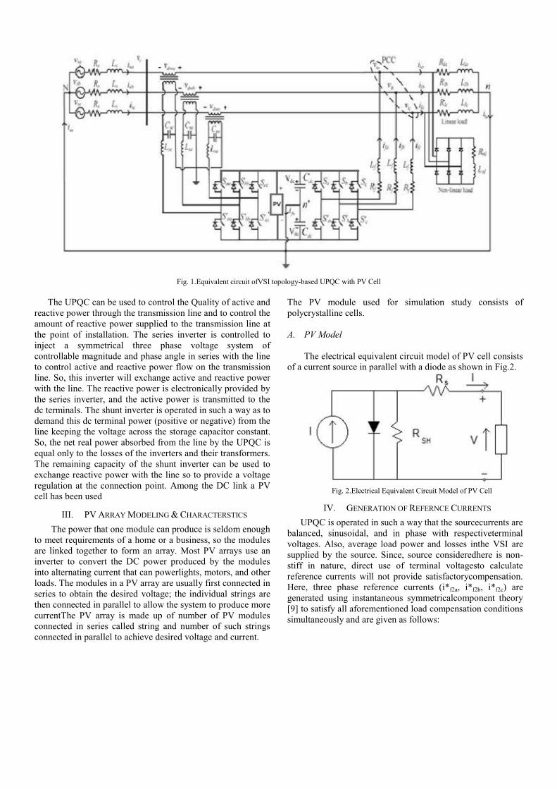
Fig. 1.Equivalent circuit ofVSI topology-based UPQC with PV Cell
The UPQC can be used to control the Quality of active andreactive power through the transmission line and to control theamount of reactive power supplied to the transmission line atthe point of installation. The series inverter is controlled toinject a symmetrical three phase voltage system ofcontrollable magnitude and phase angle in series with the lineto control active and reactive power flow on the transmissionline. So, this inverter will exchange active and reactive powerwith the line. The reactive power is electronically provided bythe series inverter, and the active power is transmitted to thedc terminals. The shunt inverter is operated in such a way as todemand this dc terminal power (positive or negative) from theline keeping the voltage across the storage capacitor constant.So, the net real power absorbed from the line by the UPQC isequal only to the losses of the inverters and their transformers.The remaining capacity of the shunt inverter can be used toexchange reactive power with the line so to provide a voltageregulation at the connection point. Among the DC link a PVcell has been used
III. PV ARRAY MODELING & CHARACTERSTICS
The power that one module can produce is seldom enoughto meet requirements of a home or a business, so the modulesare linked together to form an array. Most PV arrays use aninverter to convert the DC power produced by the modulesinto alternating current that can powerlights, motors, and otherloads. The modules in a PV array are usually first connected inseries to obtain the desired voltage; the individual strings arethen connected in parallel to allow the system to produce morecurrentThe PV array is made up of number of PV modulesconnected in series called string and number of such stringsconnected in parallel to achieve desired voltage and current.
The PV module used for simulation study consists ofpolycrystalline cells.
A. PV Model
The electrical equivalent circuit model of PV cell consistsof a current source in parallel with a diode as shown in Fig.2.
Fig. 2.Electrical Equivalent Circuit Model of PV Cell
IV. GENERATION OF REFERNCE CURRENTS
UPQC is operated in such a way that the sourcecurrents arebalanced, sinusoidal, and in phase with respectiveterminalvoltages. Also, average load power and losses inthe VSI aresupplied by the source. Since, source consideredhere is non-stiff in nature, direct use of terminal voltagesto calculatereference currents will not provide satisfactorycompensation.Here, three phase reference currents (i*f2a, i*f2b, i*f2c) aregenerated using instantaneous symmetricalcomponent theory[9] to satisfy all aforementioned load compensation conditionssimultaneously and are given as follows:

= - = - ( )
= - = - ( ) (1)
= - = - ( )where, v+
tal, v+tbl, and v+
tc1are fundamental positivesequencevoltages at the respective phase load terminal andΔ+
1=( v+tal)2+( v+
tbl)2+( v+tcl)2. Here, Plavgrepresents
average loadpower and Plossrepresents the total looses in theinverter.Average load power is calculated using a movingaveragefilter for better performance during transients and canhavea window width of half cycle or full cycle dependinguponthe type of harmonics present in the load currents.Totallosses in the inverter Ploss, computed using aproportionalintegral(PI) controller, helps in maintaining the dclink voltage(vdc1 + vdc2) at a predefined reference value (2Vdcref) bydrawing a set of balanced currents from the sourceand isgiven as follows:
(2)
Where, Kp, Ki, and e = 2Vdcref-(vdc1+vdc2) areproportionalgain, integral gain, and voltage error of the PIcontroller respectively.An error current control signal, u(t) isobtained by subtractingactual filter injected currents at loadside from the referencefilter currents. u(t) is regulated arounda predefined hysteresisband h using hysteresis currentcontroller (HCC) and IGBTswitching pulses are generatedaccording to relationship givenbelow:If u(t) ≥h, then upper switch of a leg is TURN ON andlowerswitch is TURN OFF.Else If u(t) ≤- h, then upper switch of a leg is TURN OFFandlower switch is TURN ON.
V. MATLAB MODELING & SIMULATION RESULTS
Fig. 3. Simulink model of power system network without UPQC
Below figure shows the source current with harmonics and sourcevoltage with distortions.
Fig. 4.Simulated wave form of Source current and Source voltagewithout UPQC.
Below figure shows the load current drawn by diode bridge rectifierand RL loads
Fig. 5.Simulated wave form of the load current.
Below figure shows the source voltage, compensating voltage andload voltage under Sag applied from 1.9 sec to 2 sec without UPQC.
Fig. 6.Simulated output wave form of Source voltage, CompensatingVoltage and Load Voltage without UPQC.

Below figure shows the simulink model of the power system networkwith UPQC
Fig. 7. Simulink model of power system network with UPQC.
Below figure shows the source current without harmonics and sourcevoltage without distortions due to UPQC
Fig. 8.Simulated wave form of Source current and Source voltagewith UPQC.
Below figure shows the load current drawn by diode bridge rectifierand RL loads
Fig. 9.Simulated wave form of the load current.
Below figure shows the source voltage, compensating voltage andload voltage under Sag applied from 1.9 sec to 2 secs with UPQC.
Fig. 10.Simulated output wave form of Source voltage,Compensating Voltage and Load Voltage with UPQC.
Fig. 11. Simulated output wave form of the Voltage across C1 and C2capacitors.
Fig. 12.Simulated output wave form of the filter side currents withUPQC.
Below figures shows the simulink model of the power systemnetwork with variable load under normal Dc link based UPQC

Fig.13. Simulink model of power system network with UPQC under normalDc link.
Below figure shows the variations in source current withoutharmonics and source voltage without distortions with UPQC undernormal Dc link
Fig. 14. Simulated wave form of variations in Source current and Sourcevoltage with UPQC under normal Dc link .
Below figure shows the variation in load currents drawn by differentdiode bridge rectifiers and RL loads
Fig. 15.Simulated wave form of the load current.
Fig. 16. Simulated output wave form filter currents not changing.
Below figure shows the power system network with UPQC with PVcell due to which even the variable loads drawing the un balancedcurrents the source currents will be in constant magnitude.
Fig.17.Simulink model of the power system network with UPQC under PV asRenewable Energy sources.
Fig.18.Simulink model of Photo Voltaic Cell for UPQC.
Below figure shows the balanced source current without harmonicsand source voltage without distortions with UPQC under Pv cell
Fig. 19. Simulated wave form of constant Source current and Sourcevoltage with PV cell based UPQC.
Below figure shows the variations in load currents drawn by differentdiode bridge rectifiers and RL loads

Fig. 20.Simulated wave form of the load current.Below figure shows the filter currents changing its magnitude form 1to 1.5 sec to reduce the variable load effects on the source currents.
Fig. 21. Simulated output wave form filter currents changing toreduce variations of source currents.
VI. CONCLUSION
UPQC topology has been proposed in this paper which has thecapability to compensate voltage sagsand current harmonics.The analysis has taken with and without UPQC under PV asrenewable energy sources. The proposed method is validatedthrough MATLAB simulation. This simulation study showsthat the source current harmonics reduced with UPQC andfinal it has proven that the best among the 4 conditions isUPQC with PV as renewable energy source, which maintainsthe source currents with constant magnitude even the loadcurrents are varying.
REFERENCES
[1]SrinivasBhaskarKaranki, NageshGeddada, Mahesh K. Mishra, and B.Kalyan Kumar, A Modified Three-Phase Four-Wire UPQC Topology WithReduced DC-Link Voltage Rating IEEE transactions on industrial electronics,vol. 60, no. 9, September[2]Rosli Omar and 2N.A. Rahim 3.Voltage Disturbances Mitigation in LowVoltage Distribution System Using New Configuration of Dynamic VoltageRestorer (DVR), World Applied Sciences Journal 10(12): 1480-1489, 2010ISSN 1818-4952 IDOSI Publications, 2010[3]S.F.Torabi, D. Nazarpour, Y. Shayestehfard, Compensation Of Sags AndSwells Voltage Using Dynamic Voltage Restorer (Dvr) During Single LineTo Ground And Three-Phase Faults, International Journal on “Technical and
Physical Problems of Engineering” (IJTPE) September 2012 Issue 12 Volume4 Number 3.[4] Sanjay A Deokar, Laxman M Waghmare, DVR Control Strategy ForDynamic Power Quality Disturbance Mitigation, International Journal ofScientific and Research Publications, Volume 2, Issue 11, November 2012[5]MR. Shaktisinh N. GOHIL, 2 PROF. M. V. MAKWANA, A ComparativeAnalysis of UPQC for Power Quality Improvement, Journal Of Information,Knowledge And Research In Electrical EngineeringISSN: 0975 – 6736| NOV 12 TO OCT 13 | VOLUME – 02, ISSUE - 02 .[6]Rosli OmarAnd NasrudinAbd Rahim, Mitigation Of Voltage Sags/SwellsUsing Dynamic Voltage Restorer (Dvr), ARPN Journal Of Engineering AndApplied Sciences, Vol. 4, No. 4, June 2009[7] M. Bollen, Understanding Power Quality Problems: Voltage Sags andInterruptions. IEEE press, New York, 1999.[8] S. V. R. Kumar and S. S. Nagaraju, “Simulation of DSTATCOM andDVR in Power Systems ,” ARPN Journal of Engineering and AppliedScience, vol. 2, no. 3, pp. 7–13, 200[9]Yash Pal†, A. Swarup* and Bhim Singh, A Novel Control Strategy of
Three-phase, Four-wire UPQC for Power Quality Improvement, Journal ofElectrical Engineering & Technology Vol. 7, No. 1, pp. 1~8, 2012.[10] S. Srikanthan and Mahesh K. Mishra, “DC capacitor voltage equalizationin neutral clamped inverters for DSTATCOM application,” IEEETransactionson Industrial Electronics, vol. 57, no. 8, pp. 2768 –2775, Aug. 2010. [11] B.Singh and J. Solanki, “A comparison of control algorithms for DSTATCOM,”IEEE Transactions on Industrial Electronics, vol. 56, no. 7, pp. 2738 –2745,July 2009[12] S. Rahmani, N. Mendalek, and K. Al-Haddad, “Experimental design of anonlinear control technique for three-phase shunt active power filter,” IEEETransactions on Industrial Electronics, vol. 57, no. 10, pp. 3364 –3375, Oct.2010.[13] M. Kesler and E. Ozdemir, “Synchronous-reference-frame-based controlmethod for UPQC under unbalanced and distorted load conditions,” IEEETransactions on Industrial Electronics, vol. 58, no. 9, pp. 3967 –3975, Sept.2011.[14] V. Khadkikar and A. Chandra, “A novel structure for three-phasefourwire distribution system utilizing unified power Quality conditioner(UPQC),” IEEE Transactions on Industry Applications, vol. 45, no. 5, pp.1897 –1902, Sept.-Oct. 2009 [15] , “A new controlphilosophy for a unified power Quality conditioner (UPQC) to coordinateload-reactive power demand between shunt and series inverters,” IEEETransactions on Power Delivery, vol. 23, no. 4, pp. 2522 –2534, Oct. 2008.