Alternative Positron-Target Design for Electron-Positron ...
Upload
mary-jamesCategory
view
213download
1
Nuclear Instruments and Methods in Physics Research A307 (1991) 207-212 207 North-Holland
A new target design and capture strategy for high-yield positron production in electron linear colliders *
Mary James 1, Rick Donahue, Roger Miller and W.R. Nelson Stanford Linear Accelerator Center, Stanford University, Stanford, CA 94309, USA
Received 17 May 1990 and in revised form 22 April 1991
Monte Carlo calculations were performed using EGS4 to simulate the production of positrons by a high-energy electron beam incident on thin wire targets. A 1 nun diameter, 10 radiation length long tungsten-alloy wire was chosen as an optimal target. The new target, combined with an appropriate capture strategy, could triple the yield of the high-energy positron production systems currently in use.
I . I n t r o d u c t i o n
Positron beams at high-energy accelerators are pro- duced in an electromagnetic cascade shower initiated by a high-energy electron beam incident on high-Z target material. To maximize positron yield, the thickness of the target is shown to be equal to shower maximum in the target material. Simulations Of the electromagnetic shower reveal that large numbers of low-energy positrons are produced as the shower progresses. Most of these low-energy positrons are reabsorbed before reaching the downstream edge of the target. Present targets have transverse dimensions on the order of 1 cm. In this article we examine the possibility of using a small diameter "wi re" target in order to allow positrons to emerge from the sides, thereby avoiding reabsorption. A different capture strategy [1] designed to maximize the capture of positrons emitted from the proposed wire target is also presented.
2. P o s i t r o n y i e l d s f r o m a w i r e t a r g e t
The EGS4 Code System [2] was used to simulate positron production in tungsten wires of varying diame- ters. The model assumed a 33 GeV electron pencil beam incident on a 6 radiation length (r.1.) wire. A Gaussian smearing was performed on the output rays to account for finite beam spots. Fig. 1 shows positron yields in the
* Work supported by Department of Energy contract DE- AC03-76SF00515.
] Present address: Reed College, Dept. of Physics, Portland, OR 97202, USA.
energy range of 5 to 20 MeV [3] for tungsten (and uranium) wires with radii ranging from 0.001 to 1 cm surrounded by vacuum. The yields are normalized to the calculated yield from a 6 r.1. semi-infinite slab of tungsten, which reasonably approximates the present SLC positron target.
YieM is defined as any positron that ultimately passes through the plane of the downstream end of the target, regardless of its distance from the central axis, its transverse momentum, or its arrival t ime at the plane [ 4 ] .
At very small wire radii, h igh -enJgy charged par- ticles and photons escape from the sides of the wire, precluding the development of a substantial electromag- netic cascade. At large wire radii the shower reaches maximum development, but many of the low-energy positrons are reabsorbed before reaching the down-
3 : i t : : : : : i : I : : : : 1 : I t : : : : t i n l
9 z >- - ~ W -
O 2 r r
O_ n l _> 1 F--
5 LU
10-s 10-2 10 q 10 0
TARGET RADIUS (crn)
Fig. 1. Yield of 5 to 20 MeV positrons from 6 r.1. wires as a function of radius (normalized to the yield from a 6 r.l.
semi-infinite tungsten target).
0168-9002/91/$03.50 © 1991 - Elsevier Science Publishers B.V. All rights reserved
208 M. James et al. / High-yield positron production in electron linear colliders
E3 ._1 LU
Z © rr I.- O o.. 2 U.I >
I - - . < ._J LU r r
o 4
t l I Vacuum-clad
/ / ~ ~ ~ Be-clad~
~ 6 e+/inc.) I I I
6 8 10 TARGET Length (tungsten r.I.)
12
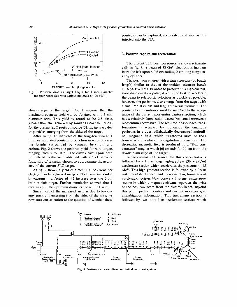
Fig. 2. Positron yield vs target length for 1 mm diameter tungsten wires clad with various materials (5-20 MeV).
s t ream edge of the target. Fig. 1 suggests tha t the m a x i m u m posi t ron yield will be ob ta ined with a 1 m m diameter wire. This yield is found to be 2.5 t imes greater than tha t achieved by similar EGS4 calculat ions for the present SLC pos i t ron source [5], the increase due to particles emerging from the sides of the target.
After fixing the d iameter of the tungsten wire to 1 mm, we s imulated pos i t ron produc t ion in wires of vary- ing lengths su r rounded by vacuum, beryl l ium and carbon. Fig. 2 shows the posi t ron yield for wire targets ranging from 5 to 10 r.1. The curves have again been normal ized to the yield ob ta ined with a 6 r.1. semi-in- finite slab of tungsten chosen to approximate the geom- etry of the current SLC target.
As fig. 2 shows, a yield of almost 100 posi t rons per electron can be achieved using a 10 r.1. wire suspended in vacuum - a factor of 4.3 increase over the 6 r.1. inf ini te slab target. Fur ther s imulat ion showed tha t 1 m m was still the op t i m um diameter for a 10 r.1. wire.
Since most of the increased yield is due to low-en- ergy posi t rons emerging from the sides of the wire, we now turn our a t ten t ion to the quest ion of whether these
posi t rons can be captured, accelerated, and successfully injected into the SLC.
3. Positron capture and acceleration
The present SLC pos i t ron source is shown schemati- cally in fig. 3. A beam of 33 G e V electrons is incident f rom the left upon a 0.6 cm radius, 2 cm long tungsten- alloy cylinder.
The posi t rons emerge with a t ime s t ructure (or bunch length) similar to that of the incident electron b u n c h ( - 6 ps, F W H M ) . In order to preserve this high-current , shor t - t ime dura t ion pulse, it would be best to accelerate the beam to relativistic velocities as quickly as possible; however, the posi t rons also emerge from the target with a small radial extent and large t ransverse momenta . The pos i t ron beam emi t tance must be matched to the accep- tance of the current accelerator capture section, which has a relatively large radial extent bu t small t ransverse m o m e n t u m acceptance. The required phase-space trans- format ion is achieved by immers ing the emerging posi t rons in a quasi-adiabat ical ly decreasing longitudi- nal magnet ic field, which t ransforms most of their t ransverse m o m e n t u m into longi tudinal m o m e n t u m . The decreasing magnet ic field is p roduced by a " f lux con- cen t ra to r" magnet which [6] extends for 10 cm from the downs t ream edge of the target.
In the current SLC source, the flux concen t ra to r is followed by a 1.5 m long, h igh-gradient (30 M e V / m ) accelerator section which accelerates the pos i t rons to 45 MeV. This high-gradient section is followed by a 0.5 m ins t rument drift space, and then one 3 m, low-gradient accelerator section. Next comes a 3 m ins t rumen ta t ion section in which a magnet ic chicane separates the orbi t of the posi t ron beam from the electron beam. Beyond this point, profi le moni tors and current moni to rs give unambiguous informat ion. This ins t rument section is followed by two more 3 m accelerator sections which
20-3C ~0 4A
't Targ i =
. I
I High Gcadient [ (girder 510) Z = 0 2 m 2.35 Booster
Caplure Seclion
K~slmn ~ SLED C~Wy
in Horizonl al Plane
~Jad,~o~ O~ooJs e+ ~ ~ u ~ 4 e ~ BPMr~
e* ~ A - - V
P~OF 7'5S
Instrument Sec~on Booster
~1 ~q Fig. 3. Positron-dedicated linac and initial transport system.

M. James et aL / High-yield positron production in electron linear colliders 209
boost the mean particle energy to 200 MeV - the design energy of the 180 ° bend magnets that steer the beam into the positron return line.
To understand and optimize positron capture down- stream of the target, the dynamics of positrons undergo- ing acceleration in a sinusoidal longitudinal electric field must be examined. The change in the particle's energy as a function of position along the central axis is given by
d7 _ eE sin/9 (1) d z mo c2 '
where mo c2 = rest mass energy of the positron, 7 = particle energy in units of m0 c2, e = charge of the positron, E = electric field strength, and z = distance along the central axis. The change in the particle's phase with respect to this accelerating field, 8, is given by
dO 2~r( 1 1 ) d z - 3 ̀ flw flz ' (2)
where 3' = wavelength of the accelerating field, flw = velocity of the accelerating wave in units of c, and flz = axial positron velocity in units of c.
Expressing flz in terms of 3' and the transverse momentum Pt in units of moc, eq. (2) becomes
dO 2 ~ ( 1 7 ) - - 2,1/2 . (3) dz 3 ̀ flw (3`2 _ 1 - P t )
For a velocity of light capture section, flw = 1. If the section is immersed in a uniform axial magnetic field, the transverse momentum, Pt can be considered con- stant, since the radial rf forces are small. For this case we can integrate eqs. (1) and (3) yielding
2nr mo c2 [ 2,tl/2~ c o s O = = c o s O X ~ - ~ 3 ` _ ( 3 ' 2 _ 1 _ p t ) ), (4)
which gives the orbits in longitudinal phase space, 3', O. Particles whose positions in phase space are on the
right side of fig. 4 are decelerated by the E field until they lag in phase enough to drop behind the field null (O = 0) and are accelerated. They eventually reach a velocity nearly synchronous with the wave velocity, after which their phase with respect to the wave is constant•
The shaded area represents the phase-space trajecto- ries of particles with transverse momenta between 0 and 2moc and with an asymptic phase of - 9 0 o. The dashed line represents particles with transverse momentum equal to 2moc. Given their higher total momen tum for the same longitudinal momentum, they are accelerated
8 0
(~ 60 - o E)')
40
uJ o9 < " r 2O I:L
0 -
ii I!i ii I I
if! 111
L J i ̧
i i i -200 -100 0 100 200
P H A S E ( d e g r e e s )
Fig. 4. Longitudinal phase-space trajectories of positrons with transverse momentum (0 < Pt < 2moc). The horizontal axis is phase with respect to the accelerating field phase null. The
vertical axis is longitudinal momentum in units of moc.
"F
o_
8°i 60
4O
2O
0
-200 - 100 I, 400
300 II I I
II1 lOO
-200 -100
2500 - 2ooo_t_,,,,_/11,,,, 1 I ILII
oo-ilii i , III
0 ~ " " ' ' '
-200 -100 PHASE
1500 v
lOOO 13_
100
(a) 80
I 2O0 -2OO
(c)
0 100
(b) 60 t 40
2O
0
-100
oov/
°°VI 1 2 0 0 r l
J 2o0
ii(d)
I uJ I O 100 200 -200 -100 0 100 200
PHASE (degrees) (e)
I 100 200
(degrees)
Fig. 5. Longitudinal emittance of positron bunch at five posi- tions along the current SLC capture system (see text). The vertical smear of points in (a) is a direct result of time not
being included in the original EGS calculations.

210 M. James et aL / High-yield positron production in electron linear colliders
less by the E field and therefore follow a trajectory with higher minimum longitudinal momenta.
Figs. 5a-5e represent the calculated longitudinal emittance of the positron bunch at five positions along the current SLC capture system. Fig. 5a represents some 63 e+/ inc ident e - emerging from the target with a phase of - 3 ps (1 o at S-band - 1 ps). Fig. 5b repre- sents the longitudinal emittance of the bunch as it emerges from the flux concentrator. The particle trajec- tories in the capture system were calculated using the ETRANS ray-tracing code [7]. The lower longitudinal- momentum particles lag in phase because of their smaller longitudinal velocities and their longer (spiral) path- lengths through the flux concentrator. By the end of the flux concentrator, the bunch has a phase extent of - 80 ps. Only 8 e+ /e - arrive at the entrance to the high- gradient accelerator section, where the mean energy is increased to - 45 MeV.
At the end of the 9 m low-gradient accelerator the bunch has a mean energy of - 190 MeV (see fig. 5c). A total of 5.3 e + / e - reach this point, 90% of which are within the transverse acceptance of the positron return line. About 70% of the remaining positrons, or 3.5 e + / e - , are within the 20 MeV acceptance of the 180 o return line bends (see fig. 5d). The length of the positron bunch determines its final energy spread at the entrance to the SLC damping rings. The 30 ps bunch length results in a 4% energy spread by the time the positrons are accelerated to 1 GeV at the entrance to the damping ring. As the damping ring acceptance is _+ 1%, a loss of 25% occurs (see fig. 5e). Thus in the current positron source, - 2.5 e + / e - arrive at the injection point of the damping ring.
4. W i r e t a r g e t a n d n e w c a p t u r e s t r a t e g y
Our proposed design combines the higher yield "wire" target with a low-gradient continuous accelera- tion capture scheme proposed in ref. [1].
To understand how to optimize the capture in longi- tudinal phase space, we look at eqs. (3) and (4). To the second order in Pt/"/ and 1/"/, eq. (3) can be approxi- mated by
dO 2,~ dz - ~ -
1 ( 1 fiww- 1 + - - + 2"/2
1 1 ]1/2 2y2
/ (5)
In a drift region "/ is constant, and if we let flw = 1, this equation represents the phase lag of a particle with energy " /and normalized transverse momentum Pt rela- tive to a velocity of light particle moving parallel to the
axis. In an adiabatically tapered magnetic field the transverse momentum varies as
-- [ B ( z ) ~1/2 P t ( z ) - P t 0 ~ } • (6)
In drifting a distance D between the e + target and the accelerator the phase slip relative to a velocity of light particle is
A 0 = ~-,, + 2 ~ 0 0 f ° B e dz . (7)
This can also be written as
( 0 2 02 1p ) A 0 = - ~-,, K + , (s)
where
1 D K = ff( fo Bz dz; (9)
B 1 = the uniform magnetic field in the capture accelera- tor section, and
Ph = the transverse momentum in the capture section. Using eqs. (4) and (6) we can find the condition for
two positrons which were created in the target at the same time to have the asymptotic phase. First, consider two positrons with Pt = 0 and different energies, "/1 and "/2. They will have the same asymptotic phase if
eE2sln~o12= 1 [ ]'2"/1 1 (10) moc -D l ~ ]'
where ~ is the mean sin 0 for the two particles as they enter the accelerator sections. Clearly, sin 0 must be positive which is the region where the particles are decelerated. We can also make the asymptotic phase O~ independent of the transverse momentum for some en- ergy "/3 chosen to be between "/1 and "/2. Using eq. (6) to find the phase with which the particles enter the acceler- ator, and eq. (4) to determine their asymptotic phase, we find the condit ion to be
e E ~ = T r - - ~"' v03 1 "y32 (11) mo cz K ("/2- 1) 1/2'
where sm~ff~o 3 is the mean value of sin 0 for the two particles entering the structure with differant transverse momenta. Again we find we want to decelerate.
If "/2 >> "/1 (in our case, they are 40 and 2, respec- tively), "/2 >> 1, and ~ = sm~ff-~0 > we can simplify further and combine eqs. (10) and (11) to yield
K "/3 - ( 1 2 )
D "/1'
1 eE2sln~m2---- 9"/1, (13)
mo£

M. James et al. / High-yield positron production in electron linear colliders 211
where K / D is the ratio of the average magnetic field in the flux concentrator (or tapered field solenoid) drift region to the constant magnetic field in the accelerator section. Since we would like to cancel the transverse momentum effect on asymptotic phase near the mini- mum energy, where it has the largest impact, we want K / D to be as near to unity as possible. This means we must taper down the magnetic field in the flux con- centrator as fast as possible, consistent with the large broad-band acceptance in transverse phase space. Sec- ondly, since the left hand side of eq. (13) is roughly the rate of acceleration in the capture region, we would like D to be rather small.
We propose to replace the first 1.5 m accelerator section and the following 0.5 m instrumentation section of the SLC positron source with a 2 m section closely coupled to the following 3 m section. This 5 m capture region is to have an accelerating gradient of 12 M e V / m .
Figs. 6a -6e represent the calculated longitudinal emittance of the positron bunch at five positions along the proposed capture system. Fig. 6a represents 195 e ÷ / e - emerging from the 1 mm diameter, 10 r.l. wire target. Low-energy positrons emerging from the sides reach the plane of the downstream edge of the target as
looi , loo_ :-t///////l/ll/l//I 60 .:i
0 0 -200 -100 0 100 200
0 : J I -200
5OO
400
T 3 0 0
v 2OO
IO0
0 - 200
-100 0 100 -100
IJ -100 100 PHASE (degrees)
200 -200
(e) 500
400
300
2O0
100
C 200 -200
0
II II -100 100 PHASE (degrees)
100 200
(f)
I 200
Fig. 6. Longitudinal emittance of positron bunch at six posi- tions along the proposed capture system (see text).
much as 100 ps behind the first positrons. Fig. 6b shows the longitudinal phase space occupied by the positrons which emerge from the flux concentrator Some 16.5 e + / e - occupy a phase extent of - 80 ps. Their distri- bution in phase space is quite similar to that of fig. 5b. Rather than inject this beam into a high-gradient accel- erator section, to minimize any further phase spread we chose to inject the beam into a back-based, low-gradient accelerating field. We chose the phase and gradient of the rf such that the phase occupied by the beam lay along the "contour lines" of the particle orbits as shown in fig. 6b. The beam's subsequent trajectory in phase space results in the smallest possible asymptotic phase spread.
In order for this strategy to work the positrons must be uniformly accelerated with no drift sections until all the positrons have energies > 10 MeV. Since some positrons are decelerated from 20 MeV down to low energy and then are reaccelerated, this takes about 30 MeV of acceleration, or about 3 m of the 5 m low-gradi- ent accelerator. Thus, for this strategy, we eliminate the 0.5 m instrumentation section that serves little purpose since both electrons and positrons are in the beam at this point.
Figs. 6c -6e illustrate the motion of the beam as it traverses the 5 m low-gradient ( E = 12 M e V / m ) accel- erator (fig. 6c), followed by 6 m of high-gradient ( E = 29 M e V / m ) accelerator (figs. 6d and 6e). We propose to replace the quadrupole focusing on the final 6 m accel- erator section with solenoidal focusing, which eliminates losses due to the represent transverse acceptance at the entrance to this structure. We find that 9.5 e + / e - arrive at the end of the 6 m low-gradient structure with a phase extent of - 15 ps. Note that most of the positrons are initially decelerated, yet the final phase spread of the beam is significantly less than that of the present source.
Because of the reduced phase extent of the beam at the 190 MeV point, only 2% are lost in the 180 ° bend leading to the positron return line (fig. 6f). The 15 ps bunch length is small enough to accelerate all particles to 1 GeV within the 1% energy acceptance of the damping ring.
Our simulations predict that 9.3 e + / e - can be pro- duced within a suitable phase space for damping ring acceptance - more than tripling the present yield.
5. Summary of results
Since it is possible to upgrade the target and capture system separately, we divided the simulations as fol- lows: 1) The production of positrons by the wire target (WT),
but injected into the current capture system (CC). 2) The production of positrons by the SLAB target
212 M. James et aL / High-yieM positron production in electron linear colliders
I I I. I
1 0 0 x = ~ o =~
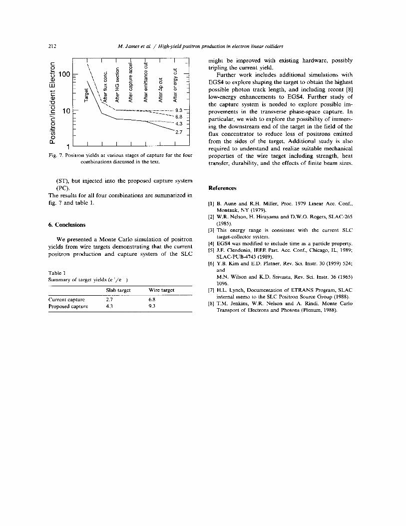
, - 10 ~.~ " " . . . . . . . :--'c-~2.~. . . . . 9.3 - - ' 6 . 8
. . . . . . . . . . . . . . . . . 4 3
a . ] I I I I I t I
Fig. 7. Positron yields at various stages of capture for the four combinations discussed in the text.
might be improved with existing hardware , possibly tr ipling the current yield.
Fur ther work includes addi t ional s imulat ions with EGS4 to explore shaping the target to ob ta in the highest possible p h o t o n track length, and including recent [8] low-energy enhancemen t s to EGS4. Fur the r s tudy of the capture system is needed to explore possible im- provements in the t ransverse phase-space capture. In particular, we wish to explore the possibil i ty of immers- ing the downs t ream end of the target in the field of the flux concent ra tor to reduce loss of pos i t rons emi t ted from the sides of the target. Addi t iona l s tudy is also required to unde r s t and and realize sui table mechanica l propert ies of the wire target including strength, heat transfer, durabil i ty, and the effects of finite beam sizes.
(ST), but injected into the proposed capture system ( P C ) .
The results for all four combina t ions are summarized in fig. 7 and table 1.
6 . C o n c l u s i o n s
We presented a M o n t e Car lo s imulat ion of pos i t ron yields f rom wire targets demons t ra t ing that the current pos i t ron produc t ion and capture system of the SLC
Table 1 Summary of target yields (e÷/e - )
Slab target Wire target
Current capture 2.7 6.8 Proposed capture 4.3 9.3
R e f e r e n c e s
[1] B. Aune and R.H. Miller, Proc. 1979 Linear Acc. Conf., Montauk, NY (1979).
[2] W.R. Nelson, H. Hirayama and D.W.O. Rogers, SLAC-265 (1985).
[3] This energy range is consistent with the current SLC target-collector system.
[4] EGS4 was modified to include time as a particle property. [5] J.E. Clendenin, IEEE Part. Acc. Conf., Chicago, IL, 1989;
SLAC-PUB-4743 (1989). [6] Y.B. Kim and E.D. Platner, Rev. Sci. Instr. 30 (1959) 524;
and M.N. Wilson and K.D. Srivasta, Rev. Sci. Instr. 36 (1965) 1096.
[7] H.L. Lynch, Documentation of ETRANS Program, SLAC internal memo to the SLC Positron Source Group (1988).
[8] T.M. Jenkins, W.R. Nelson and A. Rindi, Monte Carlo Transport of Electrons and Photons (Plenum, 1988).