Pemeriksaan Segmen Anterior Dr.halimah Pagarra, Sp.M(K); Dr.junaedi Sirajuddin, Sp.M(K)

A NEW STRUCTURE OF 12S-8P HYBRID
EXCITATION FLUX SWITCHING MOTOR USING
SEGMENTAL ROTOR
HASSAN ALI SOOMRO
UNIVERSITI TUN HUSSEIN ONN MALAYSIA

UNIVERSITI TUN HUSSEIN ONN MALAYSIA
STATUS CONFIRMATION FOR MASTER’S THESIS
A NEW STRUCTURE OF 12S-8P HYBRID EXCITATION FLUX
SWITCHING MOTOR USING SEGMENTAL ROTOR
ACADEMIC SESSION : 2015/2016
I, HASSAN ALI SOOMRO, agree to allow this Master’s Thesis to be kept at the Library under the
following terms:
1. This Master’s Thesis is the property of Universiti Tun Hussein Onn Malaysia.
2. The library has the right to make copies for educational purposes only.
3. The library is allowed to make copies of this report for educational exchange between
higher educational institutions.
4. ** Please Mark (√)
CONFIDENTIAL
(Contains information of high security or of great
importance to Malaysia as STIPULATED under the
OFFICIAL SECRETS ACT 1972)
RESTRICTED
(Contains restricted information as determined by
the Organisation/institution where research was
conducted)
FREE ACCESS
_________________________
Approved by,
__________________________
(WRITER’S SIGNATURE)
(SUPERVISOR’S SIGNATURE)
Permanent Address :
H.NO; 06, VIP ROAD BHANGWAR
COLONY, NAWABSHAH, SINDH,
PAKISTAN.
Date: ______________________
Supervisor’s name
DR. ERWAN BIN SULAIMAN
Date : ________________________
NOTE:
** If this Master’s Thesis is classified as CONFIDENTIAL or RESTRICTED,
Please attach the letter from the relevant authority/organisation stating
reasons and duration for such classifications.

A NEW STRUCTURE OF 12S-8P HYBRID EXCITATION FLUX SWITCHING
MOTOR USING SEGMENTAL ROTOR
HASSAN ALI SOOMRO
A thesis submitted in
fulfilment of the requirement for the award of the
Degree of Master of Electrical Engineering
Faculty of Electrical & Electronic Engineering
Universiti Tun Hussein Onn Malaysia
MARCH, 2016

ii
I hereby declare that the work in this thesis is my own except for quotations and
summaries, which have been duly acknowledged.
Student : ……………………………………………………
HASSAN ALI SOOMRO
Date : …………………………………………………….
Supervisor : …………………………………………………….
DR. ERWAN BIN SULAIMAN
DECLARATION
15 MARCH, 2016

iii
DEDICATION
To my beloved mother and father
DEDICATION

iv
ACKNOWLEDGEMENT
In the name of ALLAH, the most Gracious and the Most Merciful.
Alhamdulillah, all praises to Allah Almighty for His grace and blessings given to me
for the completion of my master’s studies successfully.
I also wish to express my gratitude to my supervisor, Dr. Erwan Bin
Sulaiman, for his guidance, invaluable help, advice, and patience on my project
research. Without his constructive and critical comments, continuous encouragement,
and good humour while facing difficulties, I could not have completed this research.
I am also very grateful to him for guiding me to think critically and independently.
I acknowledge, with many thanks, to the Office for Research, Innovation,
Commercialization and Consultancy Management (ORICC) for awarding me
scholarship for my master’s programme. I am much honoured to be the recipient for
this award. Receiving this scholarship has secured my financial position and
provided me the motivation and drive to successfully complete my studies.
Without support from the technical staff and my lab fellows of FSM research
group, this research would not have been undertaken. My sincere thanks to all my
FSM group friends who facilitated me every time with their technical knowledge.
It has been a very pleasant and enjoyable experience to work in UTHM with
a group of highly dedicated people, who have always been willing to provide help,
support, and encouragement whenever needed. I would like to thank all my friends
during my stay in UTHM. Life would never have been that exciting and joyful
without you.
Finally, I would like to give my sincerest gratitude to my parents for their
endless love, support, and for always making compromises to let me try whatever I
consider is worth doing.

v
ABSTRACT
The efficient use of energy enables commercial and industrial facilities to minimise
production costs, increase profits, and stay competitive. The majority of electrical
energy consumed in most industrial facilities is used to run electric motors.
Therefore, there is a need for researchers to develop advanced electric motors with
less cost and high efficiency. There has been a recent interest in flux switching motor
(FSM) in which all flux sources are positioned in stator that make the rotor simple,
robust, and brushless. The development of research has been with toothed rotor
structures, which exploit changes of paths for the stator teeth, but this structure
produces less torque and power. Hence, the use of a segmental rotor structure has
been developed, which gives significant gains. The primary function of the segments
is to provide a defined magnetic path for conveying the flux to adjacent armature coil
in stator as the rotor rotates. This design gives shorter end-winding than with a
toothed rotor structure, which requires fully-pitched coils. Hence, permanent magnet
FSM (PMFSM) and field excitation FSM (FEFSM) with segmental rotor have been
developed, but due to their infirmity of less torque generation inherit from less flux
linkage, a new structure of hybrid excitation FSM (HEFSM) is proposed. The
proposed design HEFSM I is analysed using a commercial 2D FEA package, JMAG-
designer software. Initially, HEFSM I has been improved and optimised by using
deterministic optimisation techniques and achieved torque and power of almost 48%
and 56% more than the initial HEFSM I, and almost 3% and 8% more than target
values respectively. Additionally, an alternate structure of HEFSM II has been
proposed, investigated, and optimised. Finally, optimised HEFSM II has achieved
torque and power almost 14% and 13% more than target values respectively. The
novel structure HEFSM II with segmental rotor has produced higher performances
than existing PMFSM and FEFSM, proving their suitability towards efficient and
reliable motors.

vi
ABSTRAK
Kecekapan penggunaan tenaga membolehkan kemudahan perdagangan dan
perindustrian bagi mengurangkan kos pengeluaran, meningkatkan keuntungan, dan
kekal berdaya saing. Sebahagian besar tenaga elektrik yang digunakan dalam
kemudahan perindustrian adalah untuk memacu motor elektrik. Oleh itu, adalah
perlu bagi para penyelidik untuk membangunkan motor elektrik dengan melibatkan
kos yang rendah dan kecekapan yang tinggi. Sejak kebelakangan ini, terdapat minat
yang dipamerkan oleh penyelidik di dalam motor fluks beralih (FSM) di mana semua
sumber fluks ditempatkan di dalam pemegun dan membuatkan pemutar lebih
ringkas, lasak dan tanpa keperluan berus karbon. Pembangunan penyelidikan telah
membuktikan bahawa struktur pemutar bergigi yang mengeksploitasi perubahan
laluan bagi gigi pemegun tetapi struktur ini menghasilkan tork dan kuasa yang
rendah. Oleh itu, penggunaan struktur pemutar bersegmen yang terkini telah
dibangunkan, yang mana telah memberikan beberapa kelebihan yang besar. Fungsi
utama segmen adalah untuk memberi laluan magnet yang ditetapkan untuk
mengalirkan fluks ke gegelung angker bersebelahan dalam pemegun pada ketika
pemutar berputar. Reka bentuk ini menjadikan hujung penggulungan lebih pendek
berbanding dengan struktur pemutar bergigi yang memerlukan gegelung sepenuhnya
bernada. Oleh itu, motor fluks beralih dengan magnet kekal (PMFSM) dan motor
fluks beralih dengan medan pengujaan (FEFSM) bersama pemutar segmen telah
dibangunkan namun disebabkan kelemahan mereka yang kurang baik dari segi
penghasilan tork akibat daripada kekurangan fluks yang berhubung, struktur baru
iaitu motor fluks beralih dengan pengujaan hibrid (HEFSM) adalah diperkenalkan.
Reka bentuk HEFSM I yang dicadangkan dianalisis menggunakan pakej komersial
2D-FEA, JMAG software ver. 13.0, yang dikeluarkan oleh JSOL Corporation. Pada
mulanya HEFSM I telah ditambahbaik dan dioptimumkan dengan menggunakan
teknik pengoptimuman berketentuan dan masing-masing mencapai tork dan kuasa
hampir 48% dan 56% lebih daripada HEFSM I yang dicadangkan dan hampir 3%

vii
dan 8% lebih daripada nilai sasaran. Sebagai tambahan, struktur alternatif HEFSM II
telah dicadangkan, disiasat dan dioptimumkan. Akhirnya HEFSM II yang
dioptimumkan telah mencapai tork dan kuasa hampir 14% dan 13% lebih tinggi
daripada nilai sasaran masing-masing. Struktur novel HEFSM II dengan pemutar
segmen menghasilkan prestasi yang lebih tinggi daripada yang sedia ada iaitu
PMFSM dan FEFSM, membuktikan kesesuaian mereka terhadap nilai kecekapan
motor dan boleh dipercayai.
viii
TABLE OF CONTENTS
DECLARATION ii
DEDICATION iii
ACKNOWLEDGEMENT iv
ABSTRACT v
ABSTRAK vi
TABLE OF CONTENTS viii
LIST OF TABLES xii
LIST OF FIGURES xiii
LIST OF SYMBOLS AND ABBREVIATIONS xviii
LIST OF PUBLICATIONS xix
LIST OF AWARDS xxi
CHAPTER 1 INTRODUCTION 1
1.1 Research Background 1
1.2 Problem Statement 3
1.3 Objectives of the Study 3
1.4 Scope 4
1.5 Thesis Outline 6
1.6 Summary of the Chapter 7
CHAPTER 2 LITERATURE REVIEW 8
2.1 Introduction 8

ix
2.2 Permanent Magnet Synchronous Motor (PMSM) 11
2.3 Field Excitation Synchronous Motor (FESM) 12
2.4 Hybrid Excitation Synchronous Motor (HESM) 13
2.5 Flux Switching Motor (FSM) 14
2.5.1 FSM Using Toothed Rotor Structure 15
2.5.2 FSM Using Segmental Rotor Structure 24
2.6 Comparison of Toothed and Segmental Rotor
Structure 27
2.7 Performance Analysis of Toothed Rotor Motors 29
2.7.1 Performance Analysis of 12S-10P FEFSM
with Toothed Rotor 29
2.7.2 Performance Analysis of HEFSM with
Toothed Rotor 33
2.8 Performance Analysis of Segmental Rotor Structure 36
2.8.1 Analysis of Flux Lines and Flux Distributions
of FEFSM with Segmental rotor 36
2.8.2 Torque Analysis vs Ja at Various Je of
FEFSM with Segmental Rotor 37
2.8.3 Performance Analysis of PMFSM with
Segmental Rotor 38
2.9 Optimisation 43
2.9.1 Traditional FSM Design 43
2.10 Summary of the chapter 45
CHAPTER 3 METHODOLOGY 46
3.1 Introduction 46
3.2 Design and Investigation of PMFEM, FEFSM,
and HEFSM with Segmental Rotor 47
3.2.1 Design of PMFSM, FEFSM, and HEFSM
with Segmental Rotor 48
3.2.2 Investigation of Operating Principle for
PMFSM, FEFSM, and HEFSM 51
3.3 Performance Analysis of PMFSM, FEFSM, and
HEFSM with Segmental Rotor 53

x
3.3.1 No Load Analysis 54
3.3.2 Load Analysis 55
3.4 Optimisation and Comparison 57
3.5 Summary of Chapter 59
CHAPTER 4 RESULTS AND DISSCUSSION 60
4.1 Introduction 60
4.2 Design and Investigation Results of FEFSM,
PMFSM, and HEFSM I 60
4.2.1 Design Results of FEFSM, PMFSM, and
HEFSM I 61
4.2.2 Investigation of Operating Principles of
PMFSM, FEFSM, and HEFSM I 63
4.3 Performance Analysis on the Basis of 2-D FEA 69
4.3.1 No Load Analysis Results 69
4.3.2 Load Analysis Results 75
4.4 Design Improvement of Initial Design of
HEFSM I 78
4.5 Performance Comparison of Initial and Improved
Design of HEFSM I 80
4.6 Optimisation of Improved design of HEFSM I 82
4.6.1 Parameter Sensitivity of Optimised Design 82
4.6.2 Performance of Optimised Design of
HEFSM I with Segmental Rotor 84
4.6.3 Torque and Power vs Speed Characteristics
of Initial Design and Optimised Design 87
4.7 Losses Analysis and Efficiencies of PMFSM,
FEFSM, Initial HEFSM I, and Optimised HEFSM I 88
4.8 Alternate Proposed Design HEFSM II with
Segmental Rotor 92
4.8.1 Design and Investigation of HEFSM II
with Segmental Rotor 93
4.9 Performance Analysis and Comparison of Initial
Design HEFSM II and Optimised Design HEFSM I 96

xi
4.9.1 Flux Distribution of Initial HEFSM II and
Optimised HEFSM II at no Load Condition 96
4.9.2 Induced EMF of initial HEFSM II and
Optimised HEFSM I 98
4.9.3 Magnetic Flux Lines and Flux Strengthening
of Optimised HEFSM I and Initial
HEFSM II 98
4.9.4 Torque vs Various Je at Various Armature
Current Densities Ja of Optimised HEFSM I
and Initial HEFSM II 100
4.10 Optimisation of Initial Design of HEFSM II 102
4.10.1 Parameter Sensitivity of Optimised Design
HEFM II 102
4.10.2 Performance of Optimised Design of
HEFSM II with Segmental Rotor 104
4.10.3 Torque and Power vs Speed Characteristics
of Optimised HEFSM II and
Optimised HEFSM I 106
4.11 Rotor Mechanical Strength Analysis 108
4.12 Losses and Efficiencies of Optimised HEFSM II 108
4.13 Summary of the Chapter 113
CHAPTER 5 CONCLUSION AND FUTURE WORKS 114
5.1 Conclusion 114
5.2 Future Works 115
5.3 Summary of the Chapter 115
REFERENCES 116

xii
LIST OF TABLES
1.1 Design restrictions and specification of HEFSM 5
1.2 Material selection for stator, rotor, armature coil,
and FEC 5
2.1 Design restrictions and specification of HEFSM 28
3.1 Design parameters of PMFSM, FEFSM and
HEFSM 49
4.1 Design specification of PMFSM, FEFSM and
HEFSM I 63
4.2 Design parameters and specification of improved
and optimised design of HEFSM I with segmental
rotor 84
4.3 Design specification of initial HEFSM I and initial
HEFSNM II 94
4.4 Design parameters and specification of initial
HEFSM II and optimised design HEFSM II with
segmental rotor 103
4.5 Detailed loss analysis of all designs of HEFSM
with segmental rotor 112
5.6 Overall performance and comparison of all designs 113

xiii
LIST OF FIGURES
2.1 The classification of the main types of electric
motors 10
2.2 Interior permanent magnet synchronous motor 12
2.3 Field excitation synchronous motor 13
2.4 Field excitation synchronous motor 14
2.5 A simplified flux-switch alternator scheme 16
2.6 Principle Operation of E-Core HEFSM 17
2.7 Three-phase structure of FSM toothed rotor 18
2.8 12S-10P PMFSM with toothed rotor 19
2.9 Operation principle of PMFSM 19
2.10 18S-14P FEFSM with toothed rotor 21
2.11 Operation principles of FEFSM 21
2.12 (a) 6S-4P HEFSM (b) 12S-10P inner
FE HEFSM 22
2.13 The operating principle of the proposed HEFSM 23
2.14 Basic segmental rotor scheme with field winding
excitation 25
2.15 Basic segmental rotor scheme with PM
excitation 25
2.16 Flux distribution in stator teeth with field
excitation 26
2.17 Basic working principle of PMFSM with segmental
rotor 27
2.18 Open circuit field distribution of FEC at four rotor
positions, θr 30
2.19 EMF of various FEC 30
2.20 Cogging torque 31

xiv
2.21 Torque and power vs speed characteristics 32
2.22 Losses and efficiency 32
2.23 Flux lines of HEFSSM by permanent magnet 33
2.24 Flux lines of HEFSSM by both permanent magnet
and DC field excitation 34
2.25 Torque and power versus speed characteristics 34
2.26 Estimated motor loss and efficiency 35
2.27 FE Coil flux lines at Je of 30A/mm2
(a) 12S-8P FESF motor (b) 24S-10P FESF motor 36
2.28 FE Coil flux distributions at Je of 30A/mm2
(a) 12S-8P FESF motor (b) 24S-10P FESF motor 37
2.29 Comparisons of maximum flux vs Je for 12S-8P
and 24S-10P FESF motor 37
2.30 Torque Vs Je 6S-8P 38
2.31 Torque Vs Je 12S-10P 38
2.32 Induced phase EMF at 500 r/min. (a) Waveform
(b) Harmonic spectra 40
2.33 Static torque of PMFSM 41
2.34 Variation of torque and motor efficiency with
current at 500 r/min 42
2.35 Power factor and terminal voltage with current
at 500 r/min 43
2.36 Flow diagram of electric machine design process
commonly used by engineers 44
3.1 General work flow chart of project implementation 47
3.2 Work flow of design and investigation 48
3.3 Work flow for coil test analysis 51
3.4 Circuit for U, V, and W coil test 53
3.5 Performance analysis flow chart 54
3.6 General flow diagram of optimisation 58
4.1 Stators of FEFSM, PMFSM, and HEFSM I 61
4.2 Design of segmental rotor of PMFSM, FEFSM,
and HEFSM I 62

xv
4.3 Design of armature coil of PMFSM, FEFSM, and
HEFSM I 62
4.4 Design of FEC of FEFSM and HEFSM I 63
4.5 Graph of 6 coil flux pattern of PMFSM 64
4.6 Graph of 6 coil flux pattern of FEFSM 65
4.7 Graph of 6 coil flux pattern of HEFSM I 66
4.8 Armature coil arrangement of PMFSM, FEFSM,
and HEFSM I with segmental rotor 67
4.9 U, V, and W fluxes in the armature coil 68
4.10 Flux distribution of (a) PMFSM (b) FEFSM and
(c) HEFSM I with segmental rotor 70
4.11 Induced voltage of PMFSM, FEFSM, and HEFSM I 71
4.12 Cogging torque of PMFSM, FEFSM, and HEFSM I 72
4.13 Magnetic flux lines of (a) PMFSM (b) FEFSM and
(c) HEFSM I 73
4.14 Flux strenghtening of FEFSM and HEFSM I 74
4.15 U phase flux of PMFSM, FEFSM, and HEFSM I 75
4.16 Torque vs Armature current densities Ja Flux
strengthening of FEFSM and HEFSM I 77
4.17 Power vs Armature current densities Ja at maximum
field current density Je 30 A/mm2 78
4.18 Improved design 79
4.19 Flux lines of Initial and Improved design 79
4.20 Flux strengthening of Initial and Improved design
of HEFSM I 80
4.21 Torque vs field current density Je at maximum
armature current density Ja of 30 Arms/mm2 81
4.22 Power vs armature current density Ja at maximum
field current density of 30 A/mm2 81
4.23 Segment span at 390 and 40
0 83
4.24 Parameters of improved design HEFSM I with
segmental rotor 83
4.25 Parameters of optimised design HEFSM I with
segmental rotor 84

xvi
4.26 Flux distribution of optimised design of HEFSM I
with segmental rotor 85
4.27 Magnetic flux lines of optimised design of HEFSM I
with segmental rotor 85
4.28 Torque vs Je for optimised design of HEFSM I with
segmental rotor 86
4.29 Power vs Ja at maximum Je of 30 A/mm2 86
4.30 Torque vs speed characteristics of initial and
optimised design of HEFSM I 87
4.31 Power vs speed characteristics of initial and
optimised design of HEFSM I 88
4.32 Torque and power vs speed characteristic. 89
4.33 Estimated coil end length, Lend 89
4.34 Motor losses and efficiencies at different operating
points 91
4.35 Iron losses and copper losses distribution 92
4.36 Design of proposed HEFSM II with segmental rotor 93
4.37 Graph of 6 coil flux pattern of (a) Armature coil 1
(b) Armature coil 3 (c) Armature coil 2
(d) Armature coil 5 (e) Armature coil 3
(f) Armature coil 6. 95
4.38 Armature coil arrangement of initial HEFSM II 96
4.39 Flux distribution of optimised HEFSM I and initial
HEFSM II 97
4.40 Induced EMF of optimised HEFSM I and initial
HEFSM II 98
4.41 Flux lines of (a) Optimised HEFSM I (b) Initial
HEFSM II 99
4.42 Flux strengthening of optimised HEFSM I and
initial HEFSM II 100
4.43 Torque vs various Je at various Ja 101
4.44 Parameters of Optimised HEFSM II with
segmental rotor 103

xvii
4.45 Flux distribution and flux lines of optimisation
HEFSM II 104
4.46 Torque characteristics of Optimised HEFSM II 105
4.47 Comparison of torque characteristics of FEFSM,
PMFSM, initial HEFSM I, optimised HEFSM I,
and optimised HEFSM II at maximum Ja of 30
Arms/mm2 105
4.48 Power characteristics vs Ja of FEFSM, PMFSM,
initial HEFSM I, optimised HEFSM I and optimised
HEFSM II at maximum Je 106
4.49 Torque vs speed characteristics of optimised
HEFSM I and HEFSM II 107
4.50 Power vs speed characteristics of optimised
HEFSM I and HEFSM II 107
4.51 Mechanical stress analysis of initial and optimised
designs of HEFSM I 109
4.52 Torque vs speed characteristics of optimised
HEFSM II 110
4.53 Motor losses and efficiencies at different operating
points 111
4.54 Iron losses and copper losses distribution 111

xviii
LIST OF SYMBOLS AND ABBREVIATIONS
A Ampere
AC Alternating Current
B Flux Density [T]
f Frequency [Hz], [rad/s]
I Current [A]
J Current Density [A/m2]
L Length [m]
N Number of turns
p Number of Poles
R Resistance [ohm]
r Radius [m]
rpm Revolution Per Minute
T Torque [Nm]
t Time [s]
V Voltage [V]
EMF Electromotive Force
FEA Finite Element Analysis
FEC Field Excitation Coil
FEFSM Field Excitation Flux Switching Machine or Motor
FSM Flux Switching Machine or Motor
HEFSM Hybrid Excitation Flux Switching Machine or Motor
HEV Hybrid Electrical Vehicles
IMs Induction Motors
PM Permanent Magnet
PMFSM Permanent-Magnet Flux Switching Machine or Motor
SRM Switched Reluctance Machine or Motor
SRM Synchronous Reluctance Machine or Motor

xix
LIST OF PUBLICATIONS
Journals:
(i) Hassan Ali, Erwan Sulaiman, Mohd Fairoz Omar, Mahyuzie Jenal,
“Design studies and performance of a novel 12S- 8P HEFSM with
segmental rotor”, Journal of Electrical Systems, 5-6 December 2015, Shah
Alam, Malaysia. (ISI).
(ii) Hassan Ali, Erwan Sulaiman, F. Khan and S.M. Naufal, “Magnetic Flux
Analysis of Various Flux Switching Motors Using Segmental Rotor for
Hybrid Electric Vehicles”, Journal of Electrical Systems, 5-6 December
2015, Shah Alam, Malaysia. (ISI).
(iii) Hassan Ali Soomro, Erwan Sulaiman and Faisal Khan, “Comparative
Performance of FE-FSM, PM-FSM and HE-FSM with Segmental Rotor”,
Applied Mechanics and Materials. Vol. no 773-774, pp. 776-780 (2015).
(SCOPUS).
(iv) Hassan Ali Soomro, Erwan Sulaiman and Mohd Fairoz Omar,
“Performance Comparison and Analysis of (HEFSM) and (FEFSM) Using
Segmental Rotor Structure”, Applied Mechanics and Materials, vol. 695,
pp. 778-782 (2015).(SCOPUS).
(v) Hassan Ali, Erwan sulaiman, Mubin Aizat and Zhafir Aizat, “Improved
Design of Three Phase Hybrid Excitation Flux Switching Motor with
Segmental Rotor”, Applied Mechanics and Materials, vol. no. 785, pp. 295-
299, (2015). (SCOPUS).

xx
Proceedings:
(i) Hassan Ali, Erwan Sulaiman, Mahyuzie Bin Jenal, Faisal Khan, “A novel
structure of hybrid excitation flux switching motor with segmental rotor”
Malaysian Technical Universities Conference on Engineering And
Technology (MUCET 2015).
(ii) Hassan Ali, E. Sulaiman, Mohd Fairoz Omar and Mahyuzie Bin Jenal,
“Comparison of Three Phase and Single Phase FEFSM with Segmental
Rotor”, 8th Malaysian Technical Universities Conference on Engineering &
Technology (MUCET 2014).
(iii) Hassan Ali Soomro, Erwan Sulaiman and Faisal Khan, “Comparative
Performance of FE-FSM, PM-FSM and HE-FSM with Segmental Rotor”,
International Integrated Engineering Summit Conference (IIES 2014).
(iv) Erwan Sulaiman, Hassan Ali, Mubin Aizat and Zhafir Aizat, “Improved
Design of Three Phase Hybrid Excitation Flux Switching Motor with
Segmental Rotor”, 9th International Power Engineering and Optimisation
Conference, (PEOCO2015).
(v) E.Sulaiman, H. Ali, and M.Z.Ahmad, “Magnetic Flux Analysis of Various
Flux Switching Motors Using Segmental Rotor for Hybrid Electric
Vehicles”, IEEE International Magnetics Conference (Intermag 2015).

xxi
LIST OF AWARDS
(i)
(ii)
Silver Medal at Malaysia Technology Expo, The Leading International
Invention and Innovation Expo, Putra World Trade Centre, Kuala Lumpur,
12-14 February, 2015.
Certificate of Participation at Research and Innovation Festival 2014,
Dewan Tunku Mahkota Ismail (DTMI), Dewan Terbuka and Dewan Sekitar
(DTMI).

1CHAPTER 1
INTRODUCTION
1.1 Research Background
As the term electrical machine includes motors and generators, machines operating
as motors utilise energy conversion, to give a greater variety of configurations and
sizes. Much of the insights in the proceeding discussion is applicable to the motoring
class of electrical machines, which is estimated to account for 60-70% of the
electrical energy utilisation in the developed world [1, 2]. The global trends and
influence of new technologies on the development of the electrical machines, in
response to economic and environmental pressures, are briefly recounted with a
reference to the position of developing flux switching machines [3].
The first concept of flux switching machine (FSM) was founded and
published in mid-1950s. FSM consists of all flux sources in the stator. Besides the
advantage of brushless machines, FSM has a single piece of iron rotor structure that
is robust, and can be used for high-speed applications, and the total control is
maintained over the field flux [4]. Firstly, a permanent magnet flux switching
machine (PMFSM), which is a permanent magnet (PM) single-phase limited angle
actuator, or more well known as Laws relay, with four stator slots and four rotor
poles was developed. It is extended into a single-phase generator with four stator
slots, and four or six rotor poles. Over the past ten years, many new FSM topologies
have been developed for various applications, ranging from low-cost domestic
appliances, automotive, wind power, aerospace, and others [5].

2
There are major advantages if both the field and armature windings of a
synchronous machine can be on the stator and all brushes are eliminated, whilst
complete control is maintained over the field flux. The operation of the motor is
based on the principle of switching flux. FSM is a form of salient rotor reluctance
machine with a novel topology, combining the principles of the induction generator
and the switched reluctance machine (SRM). The concept of FSM involves changing
the polarity of the flux linking the armature winding by motion of the rotor [6].
In general, there are three main classes of FSM, namely PMFSM, having only
permanent magnet for their main flux source; field excitation flux switching machine
(FEFSM), having only field excitation coil (FEC) for their main flux sources; and
hybrid excitation flux switching machines (HEFSM). Hybrid excitation flux
switching machines (HEFSMs) are those which utilize primary excitation by
permanent magnets (PMs) and secondary excitation by means of DC field excitation
coil (FEC). Normally, PMFSMs have relatively poor flux weakening performance
but can be operated beyond base speed in the flux weakening region by means of
controlling the armature winding current. By applying negative d-axis current, the
PM Field can be counteracted but with the disadvantage of increase in copper loss
and thereby reducing the efficiency, reduced power capability, and also possible
irreversible demagnetization demagnetisation of the PMs. Thus, HEFSM is an
alternative option where the advantages of both PM machines and DC FEC
synchronous machines are combined. As such, HEFSMs have the potential to
improve flux weakening performance, power and torque density, variable flux
capability, and efficiency, which have been researched extensively over many years
[7, 9].
On the other hand, recently researchers have developed the use of segmental
rotor construction for SRMs and two-phase flux switching motors, which give
significant advantages over other topologies. Whereas segmental rotors are used
traditionally to control the saliency ratio in synchronous reluctance machines, the
primary function of the segments in this design is to provide a defined magnetic path
for conveying the field flux to adjacent stator armature coils as the rotor rotates. As
each coil arrangement is around a single tooth, this design gives shorter end-
windings than the toothed rotor structure, which requires fully-pitched coils. There
are significant advantages with this arrangement as it uses less conductor materials
and may improve the overall motor efficiency. There is a choice to use either a field

3
winding or PM, or a combination of both for primary excitation [10]. More recently,
rotors with segments have been used in a novel way to produce bipolar flux linkages
in the armature windings, promising higher torque densities. This arrangement
enables use of single-tooth concentrated windings, reducing power loss, and saving
copper [11]. Topologies for three-phase segmented-rotor flux-switching machines
employing a DC field winding are presented in [12] and examined on the basis of the
peak armature flux linkage, induced phase EMF, and torque capability. The basic
principle of these types of machines is based on an unconventional configuration,
using a segmental rotor to modulate and switch polarity of the flux linkages in the
armature windings.
1.2 Problem Statement
In recent researches, segmental rotor FSM is designed in a manner such that bipolar
flux is achieved in armature winding. However, the main problems of three-phase
segmented-rotor flux-switching machines employing a DC field winding and PM are
less torque generation, high cost, and low efficiency. Besides these, flux in PMFSM
with segmental rotor cannot be controlled because of constant flux production. On
the other hand, flux strengthening in FEFSM with segmental rotor is very weak. [13,
14]
A new structure of hybrid excitation flux switching motor HEFSM using
segmental rotor is proposed in this work to overcome these problems, and designed
in which both permanent magnet and field excitation coil are used to generate bipolar
flux in armature coil to produce maximum torque and high efficiency. The amount of
copper losses and the weight of this new structure will be compared with the
PMFSM and FEFSM to see if significant reduction can be achieved. Also, due to the
use of FEC, flux can be easily controlled, and due to PM, flux strengthening will also
be increased.
1.3 Objectives of the Study
The main objective of this study is to develop a new structure of HEFSM using
segmental rotor that will have a much lower copper losses and lighter than PMFSM

4
and FEFSM. To achieve the main objective, there are some specific objectives that
have to be fulfilled, which are:
(i) To design and investigate the operating principle of PMFSM, FEFSM,
and HEFSM using segmental rotor.
(ii) To analyse the performance of PMFSM, FEFSM, and HEFSM
including no load and load conditions such as cogging torque, flux
distribution, EMF, and torque characteristics.
(iii) To optimise the performance characteristics of HEFSM with
segmental design.
1.4 Scope
The design restrictions, target specifications, and parameters of the proposed
12Slots-8Poles HEFSM using segmental rotor for HEV applications are listed in
Table 1.1. The electrical restrictions related with the inverter such as maximum 415V
DC bus voltage and maximum 100 A inverter current are set. Assuming the water
jacket system is employed as the cooling system for the machine, the limit of the
current density is set to the maximum 30Arms/mm2 for armature winding and
30A/mm2
for FEC, respectively. The outer diameter, the motor stack length, the rotor
diameter, and the air gap of the main part of the machine design being 150 mm, 70
mm, 60 mm, and 0.3 mm respectively, are identical with those existing FEFSM and
PMFSM using segmental rotor. The materials used for stator, rotor, PM, armature
coil, and FEC are illustrated in Table 1.2. Commercial FEA package, JMAG-
Designer ver.13.0, released by Japan Research Institute (JRI) is used as 2D-FEA
solver for this design.

5
Table 1.1: Design restrictions and specification of HEFSM [15]
Items 12S-8P HEFSM
Max. DC-bus voltage inverter (V) 415
Max. inverter current (A) 100
Max. current density in armature winding, JA (Arms/mm2) 30
Max. current density in excitation winding, JE (A/mm2) 30
Stator outer diameter (mm) 150
Stator yoke depth (mm) 11
Stator tooth width (mm) 12.5
Rotor diameter (mm) 90
Segment span (degrees) 40°
Segment separation (degrees) 5°
Air gap length (mm) 0.3
Number of turns per field tooth coil 44
Number of turns per armature tooth coil 44
Table 1.2: Material selection for stator, rotor, armature coil, and FEC [16]
Parts Material use
Stator 35H210
Rotor 35H210
Armature coil Copper
FEC Copper
PM NEOMAX35AH
6
1.5 Thesis Outline
This thesis deals with the design, investigation, and optimisation of a new structure
(HEFSM) employing segmental rotor. Basically, this thesis is divided into five
chapters and the summary of each chapter is given below.
(a) Introduction
The first chapter introduces the research including the background of FSM
and explanation regarding toothed and segmental rotor. Problems of existing
motors employing segmental rotor, research objectives, research scope, and
methodology are discussed in this chapter.
(b) Literature Review
This chapter explains the literature of electrical motor and classification of
electrical motor including flux switching motors. The study design and
analysis of toothed and segmental rotor are also explained in this chapter.
Finally, the optimisation process is also discussed in this chapter.
(c) Methodology
This chapter describes the project implementation of this research. The
project implementation is divided into three parts including design, analyses,
and optimisation. The design is divided into two parts, which are geometry
editor and JMAG-Designer. Then, the design is analysed at no load and load
conditions such as flux linkage, cogging torque, induced voltage and torque,
and power vs. maximum Je. Finally, the “deterministic optimisation method”
is used and treated to all parameters until the optimum performances are
achieved.
(d) Results
This chapter describes performances of PMFSM, FEFSM, and proposed
HEFSM using segmental rotor. This chapter is divided into three parts:
design and investigation results, performance analysis, and optimisation.
Initially, the design and performance of proposed design HEFSM I was
analysed at load and no load conditions on the basis of 2-D FEA. The initial
design of HEFSM was then improved by relocating the PM position and by
using optimisation technique to achieve adequate and target results. An
alternate structure of HEFSM with segmental rotor was proposed by reducing
the number of FEC coil slots and PMs. Finally, the proposed design HEFSM

7
II was optimised and achieved the target values such as maximum torque and
power with smooth flux distribution around the stator and rotor segments.
(e) Conclusion
The final chapter describes and concludes the research and the comparison of
analysis of the research with previous work. Suggestions for future work are
described in this chapter.
1.6 Summary of the Chapter
In this chapter, the introduction about FSM has been explained including
tooth rotor structure and segmental rotor machines. The problems and
drawbacks of existing motors employing segmental rotor, research scope, and
research methodology have been discussed.

2CHAPTER 2
LITERATURE REVIEW
2.1 Introduction
A motor or an electrical motor is a device that has brought about one of the biggest
advancements in the fields of engineering and technology ever since the invention of
electricity. An electric motor is an electro-mechanical device that converts electrical
energy into mechanical energy. The very basic operating principle of an electrical
motor lies on the fact that force is experienced in the direction perpendicular to
magnetic field and the current, when field and electric current are made to interact
with each other. Electric motors are always associated with involving rotating coils,
which are driven by the magnetic force. This force is produced by a reaction between
magnetic field and magnetic current. Equation (2.1) and Equation (2.2) show the
voltage and torque of DC motor respectively. Ever since the invention of motors, a
lot of advancements have been taken place in this field of engineering and it has
become a subject of extreme importance for modern engineers [17-18].
(2.1)
(2.2)
where E is the voltage applied, Eb is the back EMF produce, Ia and Ra are the
armature current and resistance respectively, T is the torque produced, ka is constant,
and ɸ is the flux produced.

9
AC electric motor can also be classified as induction motors (IMs),
synchronous motors (SMs), and switch reluctance motors (SRMs), as illustrated in
Figure 2.1. IMs are well-suited to applications requiring variable speed operation. It
is made up of the stator, or stationary winding, and the rotor. It is called “IMs”
because the rotor voltage is induced in the rotor windings instead of physically
connected by wires [19-20]. Additionally, it is built without the main DC field circuit
at all. The distinguishing feature of IMs is that no DC field current is required to run
the motor. It operates on the basis of interaction of induced rotor currents and the air
gap field [21].
The first reference to the term SRMs was made by Nasarin in 1969 and the
term became popular from 1980s onwards, through the efforts of the first commercial
exploiters of the technology, Switched Reluctance Drives Ltd. SRMs do not contain
any permanent magnets and the operation of stators is the same as brushless DC
motors while the rotors consist only of laminated iron. The operation of the SRM
where the salient poles tend to align to minimise reluctance in normal operation leads
to high normal forces acting on the stator structure. Harmonics of these normal
forces will resonate at the natural frequency resonant modes of the stator structure,
thus producing acoustic noise [23].

10
Electrical
Motor
DC Motors AC Motors
Induction
Motor (IM)
Field Excitation (FE)
SRM
Hybrid excitation
(HE) SRM
Permanent magnet
(PM) SRM
Synchronous
Motor (SM)
Switched Reluctance
Motor (SRM)
Flux Switching Motor
(FSM)
Figure 2.1: The classification of the main types of electric motors [22]
On the other hand, SMs are AC motors that have a field circuit supplied by an
external DC source. The stator has electromagnets, resulting in the creation of a
magnetic field, which rotates in time with the oscillations of the line current. The
rotation period of SM is equal to an integral number of AC cycles. Equation (2.3)
and equation (2.4) show the speed and voltage of synchronous motors [23].
(2.3)
(2.4)
where S is the speed of rotor, f is the frequency, P is the number of poles, I is
the current, and ɸ is the flux.
SMs can be classified as permanent magnet synchronous motors (PMSMs),
field excitation synchronous motors (FESMs), hybrid excitation synchronous motors
(HESM), and flux switching motor (FSM). The rotor of PMSM contains PM, the

11
rotor for FESM has field excitation (FE) winding, while the rotor for HESM is the
combination of both PM and FE, and FSM is a type of SM that contains robust rotor
structure without PM and FE winding [24].
2.2 Permanent Magnet Synchronous Motor (PMSM)
A permanent magnet synchronous motor (PMSM) is a motor that uses permanent
magnets to produce an air gap magnetic field rather than using electromagnets. These
motors have significant advantages, attracting the interest of researchers and
industries for applications such as traction, automobiles, robotics, and aerospace
technology. Permanent magnet synchronous machines have been applied to servo
drives for a long time, and nowadays, there are quite a number of large permanent
magnet synchronous machines available for industrial use. In wind generators, the
development is currently in the direction of permanent magnet machines. In
principle, vector control is required for controlling the PMSMs [25].
The basic idea of the vector control algorithm is to decompose stator currents
into a magnetic field-generating part and a torque-generating part. Both components
can be controlled separately after decomposition. The structure of the motor
controller (vector control controller) is almost the same as a separately excited DC
motor, which simplifies the control of a PMSM The vector control of the PMSM is
derived from its dynamic model. Considering the currents as inputs, the three
currents and torque are shown in equations (2.5), (2.6), (2.7), and (2.8) respectively
[26]. Figure 2.2 shows the structure of interior PMSM.
(2.5)
(2.6)
(2.7)
(2.8)
Where α is the angle between the rotor field and stator current phases, ωr is the
electrical rotor speed.

12
PMs
Figure 2.2 Interior permanent magnet synchronous motor [26]
2.3 Field Excitation Synchronous Motor (FESM)
Synchronous motor drives are well-suited for rolling mill applications, where good
performance is required both at zero and high speed in field weakening. Synchronous
machines are used mainly in large drives, for example rolling mill drives in steel
factories. Especially in applications, where a widespeed range is needed, electrically
excited synchronous motor drives are preferred due to their large field weakening
range. During the past decade, a new control method called DTC (Direct Torque
Control) has been developed for electrical machines. DTC has been first applied to
asynchronous motor drives. According to the experience of Pyrhonen, DTC control
method is applicable to synchronous motor drives as well. With a nominal stator flux
linkage, the excitation control has an important role of current balancing reactive
power control, because stator currents are not controlled in DTC, but the reactive
power balance is defined totally by the excitation control. In the field weakening
range, the excitation control defines the static and dynamic limits for the DTC
controlled synchronous motor drive performance. [27].
In rolling mill applications, high torque is required in the whole speed range.
In the case of an inverter drive, this means over dimensioning of the stator inverter,
because large torque requires more current when the flux is reduced. The load angle
gets high in the field weakening range, and the torque producing stator current
component is mainly on the d-axis. To keep the drive stable, we must compensate the
large d-axis stator current component with a high excitation current. Thus, the

13
excitation current may be the limiting factor for the maximal torque, and the
maximal stator current cannot be used. Figure 2.3 shows the diagram of a field
excitation synchronous motor [28].
Figure 2.3: Field excitation synchronous motor [28]
2.4 Hybrid Excitation Synchronous Motor (HESM)
The hybrid excitation synchronous motor (HESM) combines the advantages of the
two abovementioned machines. Therefore, HESM is of great significance for it
widens the flux regulation range, which is a crucial requirement in many applications
such as electrical propulsion and generation systems. Researchers have proposed
several structures of HESM. Spooner and Khatab presented a variety of hybrid
configurations of AC and DC machines [29], such as the hybrid excitation
synchronous machines that combine permanent-magnet (PM) excitation with wound
field excitation, as shown in Figure 2.4. The goal behind using two excitation field
sources is to combine advantages of PM excited machines and wound field
synchronous machines. Wound field excitation is used to control excitation flux in
the air gap, which improves flux weakening capability. Hybrid excitation allows the
design of machines with a relatively low armature magnetic reaction by controlling
excitation flux and at the same time, the extension of the speed operation range.
Furthermore, it improves efficiency in the most frequently used operating zones of
the traction motor. Machines with a relatively low armature magnetic reaction have
better power factor, which implies a lower power rating for the power converters
connected to them. From the design’s point of view, hybrid excitation offers an
Rotor Pole
Stator Pole
DC Source

14
additional degree of freedom and improves energy efficiency of the traction motor.
The degree of freedom is the hybridisation ratio α of the hybrid excitation machines.
It is the ratio of the PM excitation flux Φa to the maximum value of the total
excitation flux Φe max [30].
Figure 2.4: Field excitation synchronous motor [30]
2.5 Flux Switching Motor (FSM)
Flux switching machines in general are typified by having all excitation sources on
the stator, providing simpler cooling options in principle, leaving the rotor to carry
neither windings nor magnets and essentially providing the brush gear and slip rings.
Another obvious advantage of this arrangement is the simplicity of the rotor, which
allows easy manufacture and attainment of relatively high speeds in operation. The
induced voltage v, in the armature system of a rotating electrical machine is
predicted by Faraday’s law at a specified mechanical angular speed wr, the change of
flux linkages dɸ, with position ɵ.as in equation 2.9 [31].
(2.9)
The theory of flux switching machine (FSM) was first founded and published
in the mid-1950s. Firstly, a permanent magnet flux switching machine (PMFSM), i.e.
permanent magnet (PM) single-phase limited angle actuator, or more well-known as
PMs Excitation coils

15
Laws relay, which have four stator slots and four rotor poles, was developed. Later, it
was extended to a single-phase generator, having four stator slots, with four or six
rotor poles. Over the past ten years so many novels and new FSM topologies have
been developed for various applications, ranging from low-cost domestic appliances,
automotive, wind power, aerospace, and others [32-33].
Generally, according to rotor structure, FSMs can be categorised into two
classes, which are FSMs using toothed rotor structure and FSMs using segmental
rotor structure.
2.5.1 FSM Using Toothed Rotor Structure
The basic and common arrangement of the flux switching machine using a toothed-
rotor is based on the principle of Rauch’s flux switch alternator, as shown in Figure
2.5 [34]. The fundamental principle is illustrated in rectilinear representation in
Figure 2.6, showing an elementary cell that contains a PM, FEC, armature winding,
and a toothed-rotor [35].
The operating principle and definition of flux switching can be described either
by changing flux in the stator or changing flux in the rotor. Figure 2.6 explains the
operating principle of E-Core HEFSM in three different conditions. In Figure 2.6(a),
both fluxes of PM and FEC flow from stator to rotor pole P2 and return back to the
stator by rotor pole P1. At this stage, it is obvious that rotor pole P2 received the flux
from the stator. Meanwhile, in Figure 2.6(b), when the rotor moves to the left side
approximately by half electric cycles, both fluxes from the stator flow to rotor pole
P3 in between FEC winding on the right side. It is clear that the stator flux switches
its polarity through rotor pole P3, as receiving flux while rotor pole P2 brings the
flux back to the stator to form a complete flux cycle. Finally, Figure 2.6(c) depicts
the condition where rotor pole P3 is in similar condition with rotor pole P2 in Figure
2.6(a) to form one electric cycle. At this stage, the flux from the stator flows through
stator teeth between PM and armature coil to rotor pole P3 while rotor pole P2 brings
the flux to the stator, simultaneously. Since the direction of both PM and FEC fluxes
are in the same polarity, both fluxes are combined and move together into the rotor,
hence producing more fluxes with a so-called hybrid excitation flux [35].

16
Based on this concept, a rotary elementary single-phase concept has been
discussed in [36], while a practical single phase concept of four U-stator cores, four
magnets, and a four-tooth rotor has been credited with industrial application [37].
More extensive developments and applications on these structures have been
published on multiphase arrangements. Figure 2.7 illustrates the main line of
evolution of the flux switching structure of three-phase toothed rotor [38]. FSMs
using toothed rotor are further divided into three categories, which are PM FSMs,
field excitation FSMs, and hybrid excitation FSMs.
Figure 2.5: A simplified flux-switch alternator scheme [34]
(a) (b)

17
Figure 2.6: Principle Operation of E-Core HEFSM [35]
(a)
(b)
(c)

18
Figure 2.7: Three-phase structure of FSM toothed rotor [38]
2.5.1.1 Permanent Magnet Flux Switching Motor (PMFSM)
Permanent magnet flux switching motor (PMFSM) is simple in construction with
robust toothed rotor structure as shown in Figure 2.8. The stator consists of PM and
armature windings. Due to this it provides some advantages such as easy cooling of
all active parts and better suitability for high-speed applications [39]. PMFSM is
popular due to its high-power density and efficiency. PMFSM uses PMs to generate
flux. The generated flux produced is fixed and will not change-diverged, which
means flux is constant [40-42].
However, in proportion of HEV becoming popular, the increase of the usage
of rare-earth magnet results in the increase of the price. This caused serious concern
about high cost [5]. The general operating principle of the PMFSM is illustrated in
Figure 2.9, where the black arrows show the flux line of PM. From the figure, when
the relative position of the rotor poles and a particular stator tooth are as in Figure
2.9(a), the flux-linkage corresponds to one polarity. However, the polarity of the
flux-linkage reverses as the relative position of the rotor poles and the stator tooth
changes as shown in Figure 2.9(b), i.e., the flux linkage switches polarity as the
salient pole rotor rotates [43].
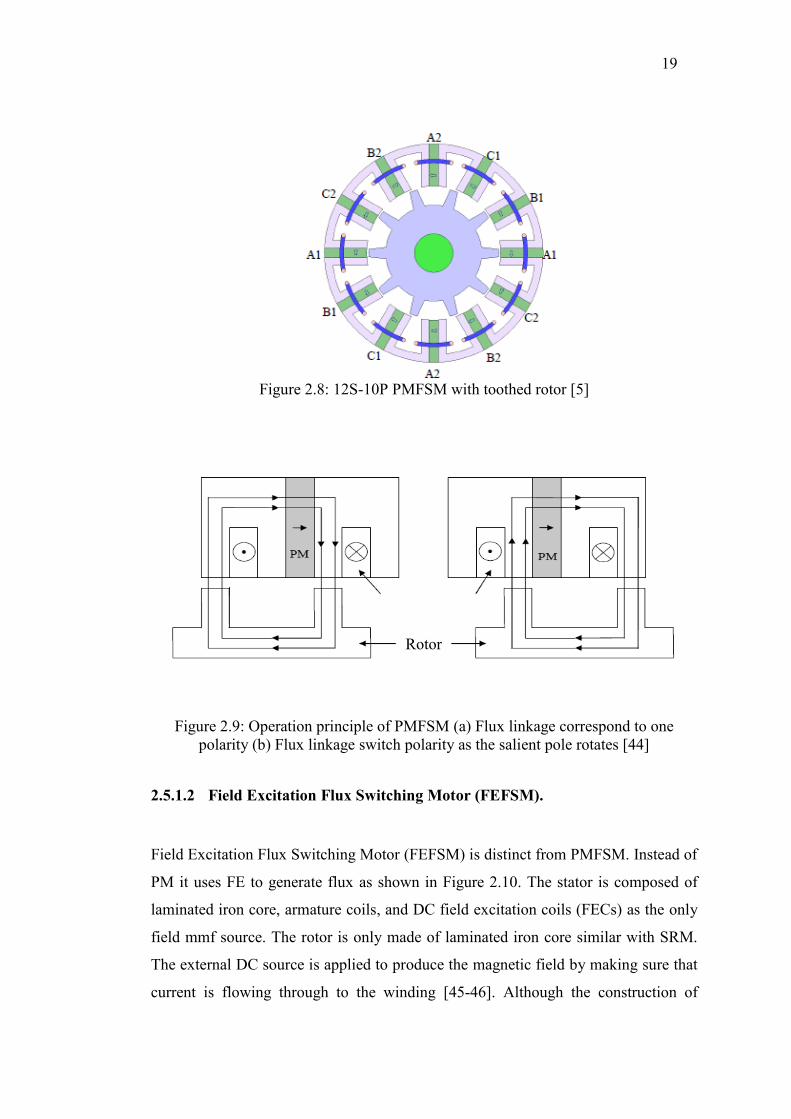
19
Figure 2.8: 12S-10P PMFSM with toothed rotor [5]
Figure 2.9: Operation principle of PMFSM (a) Flux linkage correspond to one
polarity (b) Flux linkage switch polarity as the salient pole rotates [44]
2.5.1.2 Field Excitation Flux Switching Motor (FEFSM).
Field Excitation Flux Switching Motor (FEFSM) is distinct from PMFSM. Instead of
PM it uses FE to generate flux as shown in Figure 2.10. The stator is composed of
laminated iron core, armature coils, and DC field excitation coils (FECs) as the only
field mmf source. The rotor is only made of laminated iron core similar with SRM.
The external DC source is applied to produce the magnetic field by making sure that
current is flowing through to the winding [45-46]. Although the construction of
(a) (b)
Rotor
Armature coil

20
FEFSM is not as simple as PMFSM because of the use of external DC source, the
main advantages of FEFSM are that it can control the flux and there is no use of rare-
earth magnet, resulting in cost reduction [47].
The operating principle of the FEFSM is illustrated in Figure 2.11. Figure
2.11 (a) and (b) show the direction of the FEC fluxes into the rotor while Figure 2.11
(c) and (d) illustrate the direction of FEC fluxes into the stator, which produces a
complete one-cycle flux. Similar with PMFSM, the flux linkage of FEC switches its
polarity by following the movement of salient pole rotor which creates the term “flux
switching”. Each reversal of armature current shown by the transition between
Figures 2.11(a) and (b), causes the stator flux to switch between the alternate stator
teeth [5].
Figure 2.10: 18S-14P FEFSM with toothed rotor [48]

21
(a) (b)
(c) (d)
Armature coil
Armature coil
Figure 2.11: Operation principles of FEFSM (a) θe=0° and (b) θe=180° flux moves
from stator to rotor (c) θe=0° and (d) θe=180° flux moves from rotor to stator [49]
2.5.1.3 Hybrid Excitation Flux Switching Motor (HEFSM)
Hybrid Excitation Flux Switching Motor (HEFSM) is the combination of PM and
FEC, where PM is used as the primary source of excitation and FEC as the secondary
source of excitation as shown in Figure 2.12. HEFSM requires significantly less
magnet and has higher torque density compared with a conventional PMFSM. To
easily adjust the main flux, which is fixed in PMFSM, HEFSM was developed to
improve the starting/low-speed torque and high-speed flux-weakening capabilities,
which are required for HEV [50-51].

22
By applying negative d-axis current, the PM flux can be counteracted but
with the disadvantage of copper loss, which reduces the efficiency and power
capability, and also possible irreversible demagnetisation of the PMs. Thus, HEFSM
is an alternative option where the advantages of both PM machines and DC FEC
synchronous machines are combined. As such, HEFSMs have the potential to
improve flux weakening performance, power and torque density, variable flux
capability, and efficiency, which have been researched extensively over many years
[52-53].
The operating principle of the proposed HEFSM is illustrated in Fig. 2.13,
where the red and blue lines indicate the flux from PM and FEC, respectively. In Fig.
2.13(a) and (b), since the direction of both PM and FEC fluxes are in the same
polarity, both fluxes are combined and move together into the rotor, hence producing
more fluxes with a so-called hybrid excitation flux.
Figure 2.12. (a) 6S-4P HEFSM (b) 12S-10P inner FE HEFSM [54]
(a
) (b
)
(a) (b)

23
Figure 2.13: The operating principle of the proposed HEFSM (a) θe=0° - more
excitation (b) θe=180° - more excitation (c) θe=0° - less excitation (d) θe=180° - less
excitation [54].
Furthermore in Fig. 2.13(c) and (d), where the FEC is in reverse polarity, only
the flux of the PM flows into the rotor while the flux of the FEC moves around the
stator outer yoke, which results in less flux excitation. An advantage of the DC FEC
is that the flux of the PM can easily be controlled with variable flux control
capabilities as well as under field weakening and or field strengthening excitation.
Overview of various FSMs, design and performance features, various machine
topologies, variable flux capability as well as their relationships with doubly-salient
PM machines and flux reversal PM machines have also been discussed in [54].
(a) (b)
(c) (d)

24
2.5.2 FSM Using Segmental Rotor Structure
In the previous sections, the discussion of flux switching machine was on rotors with
toothed or salient structure rotor. With a complete loop coil-turn arrangement, a
standard configuration in electrical machines with multi-turn windings, the windings
are long-pitched, if not fully-pitched, and invariably overlap. For switched reluctance
motor configurations, an arrangement has been suggested for producing mutual
coupling of single-tooth coils using a segmental rotor. This configuration maintains
the production of higher torque densities by the principle of the changing mutual
inductance, and has a further advantage of reduced copper usage and power loss due
to shorter end-windings. Meanwhile, the use of a segmental rotor as applied to flux
switching machines has been proposed by another researcher for field-winding
excitation into one with single-tooth windings [56]. Thus, for flux switching
machines employing a segmental rotor, there is, firstly, the attraction of achieving
higher torque densities due to operating with bipolar flux and secondly, a reduction
of copper losses and material due to shorter end-windings.
Figure 2.14 and Figure 2.15 show the basic principle of FSMs using a
segmented rotor with field excitation winding and with PM, respectively. For the two
rotor positions shown in the figures, while the field flux F1 and F2 are unchanged,
there is a change of polarity of the armature flux linkages on A1 and A2 as the rotor
segments S1 as S2 rotate. It is easy to follow that the scheme can be implemented
with PM excitation by replacing the field winding on F1 and F2 with radially acting
PMs on the field teeth structures, as shown in Figure 2.15. In practice, significant
benefits of short endings appear with the 8/4-configuration if a single-phase topology
is sought, whilst the 12/6 is another possible configuration with significantly shorter
end-windings [57].