A new probe for measuring small electric fields in … new probe for measuring small electric fields...
10
A new probe for measuring small electric fields in plasmas FL L. Stenzel Department of Physics, Um’uersity of California, Los Angeles, Calr’ fornia 90024-1547 (Received 25 June 1990; acceptedfor publication 17 September 1990) A dipolar double probe has been developedfor in’siru measurements of small electric fields in laboratory plasmas. The probe measures dc to ac electric fields (OQS 20 MHz) with high sensitivity (Emi”= 10 pV/cm) and responds to both space charge electric fields (E,, = - V#P) and inductive electric fields (Ei = - dA/dt). Using voltage-to-frequency conversion, the probe signal is obtained free of errors and loading effects by a transmission line. Various examplesof useful applications for the new probe are presented, such as measurements of (i) dc ambipolar fields, (ii) ac space-charge fields of ion acoustic waves, (iii) ac inductive fields of whistler waves, and (iv) mixed inductive and space-charge electric fields in current-carrying magnetoplasmas. I. INTRODUCTlON Although for many problems in plasma physics the knowledgeof electric fields is important, there are not too many reliable methods to measure small time-varying elec- tric fields in collisionless plasmas. While strong electric fields can be measured with spectroscopic techniques (Stark effect) I*’or deflections of particle beams,3P4 weaker fields are mostly obtained with probes or antennas. Space- charge electric fields can be derived from local measure- ments of the plasma potential, E = - V4P, using Lang- muir probes5’6 or emissive probes.“* Inductive electric fields, E = - aA/&, in general require the knowledge of all currents in spaceand time so as to calculate the vector potential A from first principles,”a method which is rarely applied.” In the general casewhere both space-charge and inductive fields are present, dipolar probes are used.“*‘2 These measurethe open-loop voltage of an insulated wire dipole with two exposedend electrodes,which is propor- tional to the component of E = - V4 - aA/dt along the dipole axis 6 Ve = E-6? The end (electrodes should measure differences in the plasma (space) potential $P but often measure differencesin the floating potential spect to ground. The resonator’sQ-value is chosenso as to yield a fast time response ( - 50 ns) and a sufficiently steep slope dV/df for frequency demodulation with high sensi- tivity (Emin? 10 pV/cm). Only a few passivecomponents are used in the voltage-to-frequencyconverter which fits into the movable probe shaft near the dipole. The entire probe has operated reliably for long times in a high- temperature environment created by a large hot cathode. Several useful applications of the probe are presented and others are suggested. From the measurement of ambi- polar electric fields and ion drifts, the effective ion-neutral collision frequency is obtained. From measurement of elec- tric and magnetic fields of whistler waves, the phaseveloc- ity, direction of propagation,and energy flow are obtained. When a current in a magnetoplasmais switched on, the propagating front contains a whistler wave electric held while in steady state, electrostatic fields build up normal to the current channel. From space- and time-resolved elec- tric field measurements, one can obtain the space-charge density, p = eV*E, and magnetic field variations, aB/ at = - VxE. 4fr=dp - (kTJe) ln( Tdnp’Time)“2, II. PROBE DESIGN AND CONSTRUCTION which is only appropriate if there are no temperature gra- dients or significant electron tails. In the present experiment a dipolar double probe is used to measure general time-varying electric fields in a Maxwellian afterglow plasma.The major new feature is the method of measuring a small open-loop voltage and trans- ferring the information from an in situ dipole to an external instrument. This task is accomplishedby applying the di- pole signal to a voltage-dependent capacitance (Varactor diode) which shifts the resonance frequency of a l-GHz L-C circuit. The transmission line only carries the frequency-modulated microwave signal, hencedoes not in- troduce signal errors due to ac pickup. The resonantcircuit represents a high impedance comparedto the probe imped- ance, hence the open-loop voltage is measured properly. The resonator is magnetically coupled to the transmission line but electrically floating, hencethe dipole is highly im- mune to large common-mode potential variations with re- The principle of operation of the dipole double probe is shown schematically in Fig. 1. An electrically insulated linear dipole of length 2d has two exposedend electrodes floating in the plasma [Fig. 1(a)]. In the presence of an electric field E due to potential gradients - V+ and/or time varying vector potentials - swat, an open-loop volt- age V, = I E*dl z 2Ed will developat the dipole terminals. This voltage is applied via two resistors 2RE 1 kSZto an L-C resonant circuit (f,,- 1000 MHz). The resistors serve to isolate the high frequency signal from the dipole (R ) l/w,,,CO). The capacitance consists of a fixed ce- ramic capacitor Ce = 10 pF and a voltage-dependent capac- itor (Gallium-Arsenide Varactor diode, Varian VAT- 11l- NlO) with 0.75 .ZZ Ccu) < 1.5 pl? for - 4< V<O V. The dipole voltage drops off essentially across the diode since the inductance (L-25 nH) has a negligible impedance comparedto that of the junction capacitance (C(,) z 1 pF) at the relatively low frequencies associated with Vdctj. The 130 Rev. Sci. Instrum. 62 (I), January 1991 @ 1990 American Institute of Physics 130 Redistribution subject to AIP license or copyright, see http://ojps.aip.org/rsio/rsicr.jsp
Transcript of A new probe for measuring small electric fields in … new probe for measuring small electric fields...

A new probe for measuring small electric fields in plasmas FL L. Stenzel Department of Physics, Um’uersity of California, Los Angeles, Calr’fornia 90024-1547
(Received 25 June 1990; accepted for publication 17 September 1990)
A dipolar double probe has been developed for in’siru measurements of small electric fields in laboratory plasmas. The probe measures dc to ac electric fields (OQS 20 MHz) with high sensitivity (Emi”= 10 pV/cm) and responds to both space charge electric fields (E,, = - V#P) and inductive electric fields (Ei = - dA/dt). Using voltage-to-frequency conversion, the probe signal is obtained free of errors and loading effects by a transmission line. Various examples of useful applications for the new probe are presented, such as measurements of (i) dc ambipolar fields, (ii) ac space-charge fields of ion acoustic waves, (iii) ac inductive fields of whistler waves, and (iv) mixed inductive and space-charge electric fields in current-carrying magnetoplasmas.
I. INTRODUCTlON
Although for many problems in plasma physics the knowledge of electric fields is important, there are not too many reliable methods to measure small time-varying elec- tric fields in collisionless plasmas. While strong electric fields can be measured with spectroscopic techniques (Stark effect) I*’ or deflections of particle beams,3P4 weaker fields are mostly obtained with probes or antennas. Space- charge electric fields can be derived from local measure- ments of the plasma potential, E = - V4P, using Lang- muir probes5’6 or emissive probes.“* Inductive electric fields, E = - aA/&, in general require the knowledge of all currents in space and time so as to calculate the vector potential A from first principles,” a method which is rarely applied.” In the general case where both space-charge and inductive fields are present, dipolar probes are used.“*‘2 These measure the open-loop voltage of an insulated wire dipole with two exposed end electrodes, which is propor- tional to the component of E = - V4 - aA/dt along the dipole axis 6 Ve = E-6? The end (electrodes should measure differences in the plasma (space) potential $P but often measure differences in the floating potential
spect to ground. The resonator’s Q-value is chosen so as to yield a fast time response ( - 50 ns) and a sufficiently steep slope dV/df for frequency demodulation with high sensi- tivity (Emin? 10 pV/cm). Only a few passive components are used in the voltage-to-frequency converter which fits into the movable probe shaft near the dipole. The entire probe has operated reliably for long times in a high- temperature environment created by a large hot cathode.
Several useful applications of the probe are presented and others are suggested. From the measurement of ambi- polar electric fields and ion drifts, the effective ion-neutral collision frequency is obtained. From measurement of elec- tric and magnetic fields of whistler waves, the phase veloc- ity, direction of propagation, and energy flow are obtained. When a current in a magnetoplasma is switched on, the propagating front contains a whistler wave electric held while in steady state, electrostatic fields build up normal to the current channel. From space- and time-resolved elec- tric field measurements, one can obtain the space-charge density, p = eV*E, and magnetic field variations, aB/ at = - VxE.
4fr=dp - (kTJe) ln( Tdnp’Time)“2, II. PROBE DESIGN AND CONSTRUCTION
which is only appropriate if there are no temperature gra- dients or significant electron tails.
In the present experiment a dipolar double probe is used to measure general time-varying electric fields in a Maxwellian afterglow plasma. The major new feature is the method of measuring a small open-loop voltage and trans- ferring the information from an in situ dipole to an external instrument. This task is accomplished by applying the di- pole signal to a voltage-dependent capacitance (Varactor diode) which shifts the resonance frequency of a l-GHz L-C circuit. The transmission line only carries the frequency-modulated microwave signal, hence does not in- troduce signal errors due to ac pickup. The resonant circuit represents a high impedance compared to the probe imped- ance, hence the open-loop voltage is measured properly. The resonator is magnetically coupled to the transmission line but electrically floating, hence the dipole is highly im- mune to large common-mode potential variations with re-
The principle of operation of the dipole double probe is shown schematically in Fig. 1. An electrically insulated linear dipole of length 2d has two exposed end electrodes floating in the plasma [Fig. 1 (a)]. In the presence of an electric field E due to potential gradients - V+ and/or time varying vector potentials - swat, an open-loop volt- age V, = I E*dl z 2Ed will develop at the dipole terminals. This voltage is applied via two resistors 2RE 1 kSZ to an L-C resonant circuit (f,,- 1000 MHz). The resistors serve to isolate the high frequency signal from the dipole (R ) l/w,,,CO). The capacitance consists of a fixed ce- ramic capacitor Ce = 10 pF and a voltage-dependent capac- itor (Gallium-Arsenide Varactor diode, Varian VAT- 11 l- NlO) with 0.75 .ZZ Ccu) < 1.5 pl? for - 4< V<O V. The dipole voltage drops off essentially across the diode since the inductance (L-25 nH) has a negligible impedance compared to that of the junction capacitance (C(,) z 1 pF) at the relatively low frequencies associated with Vdctj. The
130 Rev. Sci. Instrum. 62 (I), January 1991 @ 1990 American Institute of Physics 130
Redistribution subject to AIP license or copyright, see http://ojps.aip.org/rsio/rsicr.jsp
d
C(V) R
L
-.-I ‘co 1% iF=-v@ -a,Oat
-l/.2 ?S o) (Lc(vd)’ d
+d;=ZdE
ps+ (large line shift)
Af
FIG. 1. Schematic drawing of the dipole double probe and its principle of operation. (a) The dipole, consisting of two conducting spheres and two insulated wires each of length d, is attached to a high-impedance reso- nance circuit containing a varactor diode. (b) The open-loop voltage of the dipole shifts the resonance frequency of the I-GHz L-C circuit. For small line shifts, frequency-demodulation on the slope of the resonance curve is suitable. The purpose of the voltage-to-frequency conversion is to eliminate errors and loading by the transmission line to the floating di- pole.
latter are restricted by 2RCo= 10 ns. At frequencies well below the plasma frequency (f Q fpk 1 GHz) the probe impedance is given by the differential resistance of its I-V curve, I (13) = zisat - Zcsate - cV/kTc, near the floating poten- tial, eVH= (kT,)ln(l,,,/Zwat), i.e., RdirE (dV/dI) y = k7’JeZ,,t. For typical plasma parameters (n,- lOI6 cm-“, AT,- 1 eV), and probe sizes (area A-50 mm2) one has Rdirz800 CR. For low frequencies the source resis- tance is much smaller than the load resistance given by the diode leakage current (RIoad= 100,...,500 kfl, to be shown below). However, with increasing frequency the load due to the capacitance C0 presents a reduced response for f L ( 2nRd,&) - ’ = 20 MHz. The dipole voltage is usually too small to bias the diode into the forward direction (V, < +a5 VI.
The resonance line of the L-C resonator sketched in Fig. 1 (b) is shifted by the diode voltage V& For large frequency shifts the entire line should be swept out while for small shifts, which are of primary interest, the frequency-demodulation can be done at the slope of the resonance curve. By applying a constant signal frequency fe and measuring the local slope (8 V,r/Jf )fO a small res- onance frequency shift Af gives rise to a proportional am-
S,ona, Generator P
Zd-2.5cm
FIG. 2. Schematic drawing of the probe construction. The dipole is con- nected via a IO-cm parallel line to the resonator, which is mounted inside a grounded metallic probe shaft. A microwave signal is magnetically coupled through the resonator, which is electrically floating with the dipole.
plitude shift AL’,, = (aP’,r/Jf )fOAf. Although a high Q resonator with a large slope would yield a high sensitivity, it would also limit the time response of the probe, t = Af - ’ = Q/f,,,. For f,,, > 1 GHz and Af N 20 MHz, a resonator with Qz 50 is appropriate. The applied rf signal to the resonance circuit is kept small ( Vrf z 1 mV) so as to avoid nonlinearities due to rectification and self-biasing of the varactor diode.
The construction of the probe and the typical measure- ment setup are sketched in Fig. 2. The dipole (2.5 cm full length, 0.5-mm-diam Cu wire, insulated with 1-mm-diam ceramic tubing) is connected via a lo-cm-long parallel line to the resonant circuit located inside a 12.5-mm-diam stainless-steel probe shaft. The shaft shields the resonator from the plasma so that frequency shifts arise only from the varactor diode. The resonant circuit and dipole are electrically floating with respect to the grounded probe shaft, which not only minimizes perturbations of the plasma (I = 0) but greatly suppresses common mode sig- nals when the plasma potential fluctuates uniformly with respect to ground.
A cw microwave signal (0.8 <f < 1.5 GHz) is applied via a 50-R coaxial cable, coupled inductively to the reso- nant circuit, and transmitted similarly to a broadband am- plifier with video detector. The rectified rf signal 1 V,rl is displayed on a digital oscilloscope synchronized to the plasma production rate.
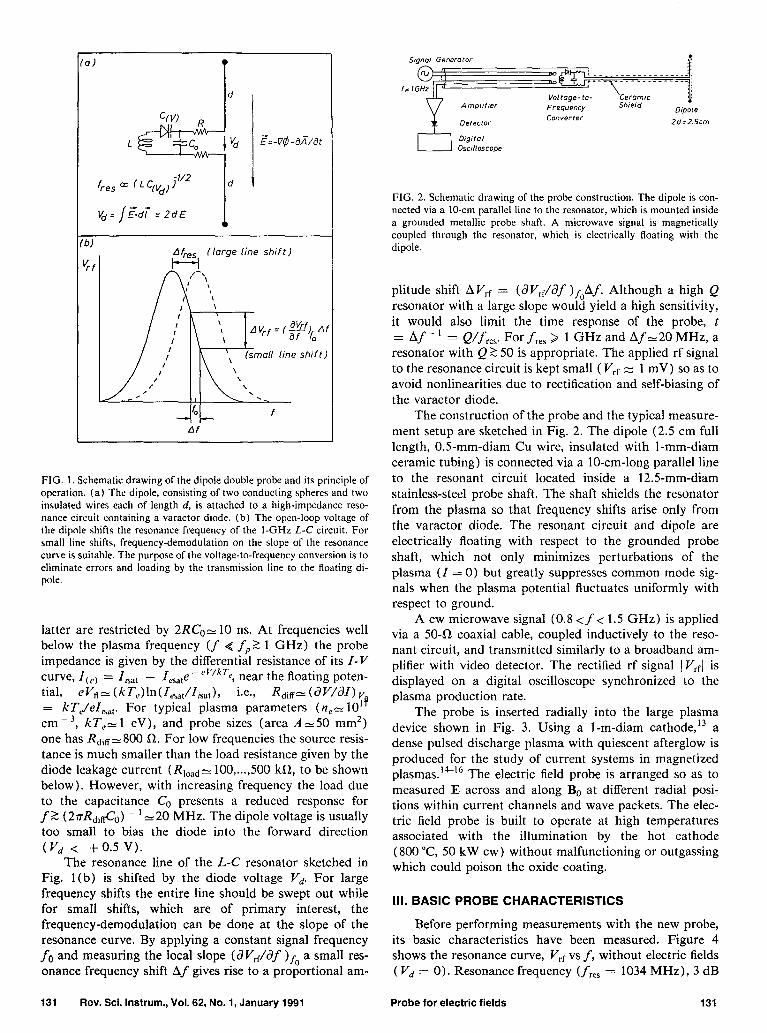
The probe is inserted radially into the large plasma device shown in Fig. 3. Using a 1-m-diam cathode,13 a dense pulsed discharge plasma with quiescent afterglow is produced for the study of current systems in magnetized plasmas.‘“‘6 The electric field probe is arranged so as to measured E across and along Be at different radial posi- tions within current channels and wave packets. The elec- tric field probe is built to operate at high temperatures associated with the illumination by the hot cathode (800 “C, 50 kW cw) without malfunctioning or outgassing which could poison the oxide coating.
III. BASIC PROBE CHARACTERISTICS
Before performing measurements with the new probe, its basic characteristics have been measured. Figure 4 shows the resonance curve, V,r vs f, without electric fields ( Vd = 0). Resonance frequency (f,,, = 1034 MHz), 3 dB
131 Rev. Sci. Instrum., Vol. 62, No. 1, January 1991 Probe for electric fields 131
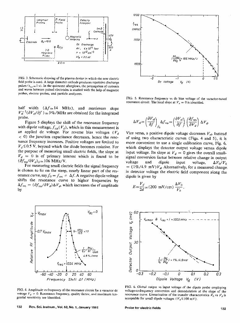
FIG. 3. Schematic drawing of the plasma device in which the new electric field probe is used. A large diameter cathode produces repetitive discharge pulses (&,z 1 s). In the quiescent afterglows, the propagation of currents and waves between pulsed electrodes is studied with the help of magnetic probes, electric probes, and particle analyzers.
half width (ADZ 14 MHz), and maximum slope Y; * (~YI’,f/af ) =S%/MHz are obtained for the integrated probe.
Figure 5 displays the shift of the resonance frequency with dipole voltage, f,.,,( Yd), which in this measurement is an applied dc voltage. For reverse bias voltages ( Vd < 0) the junction capacitance decreases, hence the reso- nance frequency increases. Positive voltages are limited to Vd50.5 V, beyond which the diode becomes resistive. For the purpose of measuring small electric fields, the slope at Vd = 0 is of primary interest which is found to be (~fre./Wd),, 106 MHz/V.
For measuring small electric fields the signal frequency is chosen to lie on the steep, nea.rly linear part of the res- onance curve, say f. = f res + Af. A negative dipole voltage shifts the resonance curve to higher frequencies by Af,, = (df,,,/i?V,)AVd, which increases the rf amplitude
4 ( , , ,~=p4;>, , , j -60 -10 -20 0 20 40 60
Frequency Shtft Af (MHz)
FIG. 4. Amplitude vs frequency of the resonance circuit for a varactor dc voltage V, = 0. Resonance frequency, quality factor, and maximum tan- gential sensitivity are identified.
132 Rev. Sci. Instrum., Vol. 62, No. 1, January 1991
Rc Voltage vd (v)
FIG. 5. Resonance frequency vs dc bias voltage of the varactor-tuned resonance circuit. The local slope at V, = 0 is identified.
AV,= ($$;fres= ($) (g) AVd
Vice versa, a positive dipole voltage decreases Vrp Instead of using two characteristic curves (Figs. 4 and 5), it is more convenient to use a single calibration curve, Fig. 6, which displays the detector output voltage versus dipole input voltage. Its slope at V, = 0 gives the overall small- signal conversion factor between relative change in output voltage and dipole input voltage, AVdVo = ( 1%/4.9 mV) Vk Alternatively, for a measured change in detector voltage the electric field component along the dipole is given by
E=$= (200 mV/cm) av,. vo
I 1 f f I
V 0max 2 f=1&j0MHz---------
I I g %3 -0.2
I 1 I I -0.1 0 0.1 0.2 0.3
Dip&e Voltqe Vd (VI
FIG. 6. Global output vs input voltage of the dipole probe employing voltage-to-frequency conversion and demoduJation at the slope of the resonance curve. Linearization of the transfer characteristics V,, vs V, is acceptable for small dipole voltages ( V,S 100 mV).
Probe for electric fields 132

I& (PA) I
Rreverse = 0.5 M Q -25
FIG. 7. dc current voltage characteristics for the varactor diode showing the typical differential resistance R = dV/dI and limit of positive dc bias due to forward conduction ( Vdc 5 + 0.5 V).
la)
lb)
I(t)
(02A, div.)
(38mV cni ‘/ div.)
This calibration holds only when the video detector voltage is proportional to the applied rf voltage, which has been found to require VOZ 10 m V for the tunnel diode in use (Microwave Associates MA-7700AM05).
The current-voltage characteristics of the varactor di- ode has been measured and is shown in Fig. 7. For reverse dc bias ( V,, < 0), the leakage resistance is R-500 k!& while for forward bias voltages up to V,,-0.5 V the resis- tance is R 2 100 kR. In this regime the diode represents a negligible load for the double probe. Although for Vdc > 0.5 V the diode no longer behaves as a capacitor, one can
always reverse the sign of the dipole voltage by a 180” rotation and thereby still measure fields with E> 1.25 V/cm.
The time response of the dipole probe is of particular interest for measuring transient electric fields. Figure 8 dis- plays the result of a test measurement in vacuum where a time-varying electric field is created by applying a pulsed voltage to a plane disk electrode. As schematically shown in Fig. 8(a), the dipole probe is placed near the electrode so as to measure the field E, along its axis. Instead of the disk voltage V(,) its derivative, i.e., the displacement cur- rent Z = C dV/dt is measured and displayed in Fig. 8(b). The 3 ps long voltage pulse has fast rise and fall times (At 5 50 ns) which are fully resolved by the electric field probe.
Finally, a test measurement of a known electric field configuration in a plasma has been performed which is explained in Fig. 9. An insulated straight wire is passed radially through the magnetized afterglow plasma (n,= 10” cm - 3, kT,S 1 eV) across the uniform axial magnetic field BO( B0 = 20 G). A current is pulsed through the wire (Z-O.8 A, At- 1 11s) such that there is an induc- tive electric field E = - aA/dt parallel to the long wire where
A,= &Z/2r) ln(@T) is the predicted vector potential in free space (Y,, is an integration constant).” Since the electric field is perpen- dicular to the magnetic field only a small cross-field current
1 <Cd? Vacuum
--__ ,y --.
‘,- -_ ,
-7
-. 4
VII, --._ z‘
- 4
I \\,- -_,
Time t (50nsec/div)
FIG. 8. Test of the time response of the electric field probe. (a) Schematic test setup for measuring the field normal to a charged disk in free space. (b) Capacitive current to the disk, I(,, = CdV/dt, and electric field E,a V(,, showing a temporal resolution Ar S 50 ns.
J = neE,xB,,/Bi is induced which, to first order, does not modify the electric field from its free-space configuration. As shown in Fig. 9(a), the dipole probe is arranged so as to measure the electric field versus radial distance from the
la
(b)
‘It, (OLiA/
divl
Ey (t) (32mV cn$‘div)
*Y(t) (Z7nVs cmi!4d;v)
Jr
Plasma
TV t Ftt, = -aCat
I===+ -7
Ayfr) = $j lnl+)
Time t (0.2 ,us/div)
FIG. 9. Test measurement of a known inductive electric field in a plasma with the new dipole probe. (a) Schematic setup consisting of a straight wire with pulsed current Zctj across B, which produces a time varying vector potential measured with the electric field probe. (b) Typical time waveform of current, electric field, and vector potential, A, = - SE,, dt.
133 Rev. Sci. Instrum., Vol. 62, No. 1, January 1991 Probe for electric fields 133

-50’ I
IO fbt ’ , I ,
AY f=OBfls
(Rvs) cm 6
4
2
a : a
0 k
0,: 270” _ Data
0
Least-square fit y=o*blnr ------A
-b =&/2n = 2.2 nVs/cm
I : IIA I # 1 1 2 3 L 5
r (Cnr)
FIG. 10. Polarization and radial field dependence of the test measure- ments described in Fig. 9. (a) Peak electric field component vs dipole angle 63 with respect to B,,. For dI/dt > 0 the induced electric field points in the direction opposite to the current flow. (b) The vector potential A,* (t = 1 ps) shows a logarithmic radial dependence from which the current in the wire is found by a least-square curve fit.
wire. Figure 9(b) shows typical waveforms of current ~0,~ electric field EYC t), and vector potential A, = - J E,,dt. The electric field arises from the time vari- ation of the current and, consistent with Lenz’s law, is induced in the direction opposite to the primary current (dI/dt > 0). The vector potential is parallel to the current and approximately follows its tirne variation. Since the di- pole can be rotated, the direction of E can be measured in the plane perpendicular to the probe shaft. Figure IO(a) shows the observed electric field component along the di- pole axis, E*d/d, versus angle 0 with respect to B,. The sinusoidal variation EC,, oc sin 0 ilndicates the proper linear polarization of the dipole and confirms that E is parallel to the wire. The spatial variation of the vector potential A,(r) versus distance r from the wire is shown in Fig. lO( b). The data confirm the logarithmic dependence and a least-square curve fit yields the current in the wire accurate to within - 20%. Thus, the dipole probe responds properly to inductive as well as to electrostatic fields.
IV. APPLICATIONS
Having tested and calibrated the new electric field probe, it will now be shown to yield useful information in various basic plasma experiments. These start with a sim- ple case of a dc space-charge field, then progress to elec- trostatic and electromagnetic wave fields, and finally show a case of a mixed field EC,, = -- VC$ - aA/dt produced by pulsed currents in a magnetized plasma.
1 1 PROBE CtiRRiffTS I :~%%?
TIME T (Zis’divl 7. I 1 I I i
xlato (b) 7
“62
/
x
co&
6-
x /
x
L , I I 1 ! I
a 5 to 15 20 2.5 30 A.? (COll
ic) Er =-2tmv/cm PO
1oF
FIG. I I. Measurement of a weak de electrostatic field in a nonuniform, unmagnetized afterglow plasma. (a) Langmuir probe traces at different axial positions from which gradients in density and plasma potential are derived. (b) Axial density profile and electric field, calculated from Bolt- zmaan’s relation, at the location of the electric field probe (Ar~5 cmf. (c) Polar plot of electric field component Ecos 6,, YS dipole angle @(, indicating E.3 - 21 mV/cm pointing in the direction opposite to Vn.
A. Ambipolar electric fields
When the pulsed dc discharge shown in Fig. 3 is op- erated without a confining magnetic field (I& = 0) the plasma exhibits an axial density gradient due to the radial loss of ionizing electrons. Figure 11 (a) shows Langmuir probe traces I( V) at different axial positions z which, upon evaluation, yield the axial electron density profile neCzI shown in Fig. 11 (b). The electron temperature kT,c= 1.16 eV exhibits a negligible gradient. The plasma potential r$,, defined by the “knee” of the I-V curve and practically obtained by the intersection of the extrapolated characteristics of the electron retardation and saturation regimes, shows an axial gradient A~$/hz= 17 mV/cm. Since the accuracy of determining the plasma potential is rather limited (Sa+,,~O.lkT,/e~O.l V), a large probe sep- aration (AZ= 25 cm) is required in order to obtain a reli- able value for the electric lield (A45,- 17 i 4 mV/cm),
134 Rev. Sci. instrum., Vol. 62, No. 1, January 1991 Probe for electric fields 134

‘d AFTERGLOW PLASMA
;;fr:y n
--IA n 6n 6F
____ AZ - ir PLANE
EXCITER -b 0 DIPOLE PROBE
‘6) 1 POLARIZATION
Time I ( 50 /z/d, vl t i 5Ops/dtvl
FIG. 12. Measurements of the time-dependent electrostatic field of an ion acoustic wave. (a) Experimental setup. (b) Probe signals at different dip4e angles Q,, showing that the electric field is polarized along the direction of wave propagation ( ed = 0’). (c) Comparison between electric field 6E:, ,, and density perturbation I%,,) which are related by Boltz- mann’s law.
hence the spatial resolution of this measurement is an or- der of magnitude worse than that of the dipole probe. Nev- ertheless, the average electric field is close to the theoreti- cally expected value for the ambipolar electric field, given by the Boltzmann relation, E = (kTJe) (Vn/n) e 18 mV/ cm, for z = 5 cm where the dipole is located.
The electric field measurement with the dipole probe is displayed in Fig. 11 (c) . The dipole voltage V, is recorded at different dipole angles ed, and the calculated electric field projection VJd = E cos 8 is displayed in a polar plot. The largest positive signal yields E-21 mV/cm ( f 10%) with the dipole pointing in the direction opposite to the density gradient. Thus, the dipole measures the appropri- ate space-charge electric field in magnitude and direction with good spatial resolution (AZ-2.5 cm).
B. ac electrostatic fields
The present experiment will show measurements cf the electric field of an ion acoustic wave, explore the sensitivity limits of the probe, and combine ion drift data with ambi- polar electric field data in order to obtain ion neutral col- lision rates.
Figure 12 (a) presents a schematic view of the experi- mental setup. A positive pulse applied to a plane electrode (15 cm diam) produces a density perturbation Sn which propagates as a sound wave in the unmagnetized nonuni- form afterglow plasma. Since the wave propagates against the ion drift ud associated with the ambipolar electric field,
c
‘b) 6E, 7 MAX
1 0.2 0.4 6 TIME t (ms)
FIG. 13. Propagation of the perturbed electric field SE, in the experiment of Fig. 12. (a) Electric field SE, vs time f at different axial distances AZ from the exciter. Fields as weak as 6E,= 10 pV/cm, corresponding to &z/n 5 9 x 10 - ‘, can be resolved by signal averaging. (b) Time-of-flight diagram for the perturbed field showing subsonic propagation speed due to a superimposed ion drift.
E, = (kT,/e) (&z/n dz), the observed phase velocity uph is lower than the sound speed, c, = ( kT,/mi)“2, uphCc, - vti The relative density perturbation &z/n is obtained
from the ion saturation current of a Langmuir probe, the wave electric field SE is measured with the dipole probe.
Figure 12(b) shows the time dependence of the electric field signal at different dipole angles. When the dipole is perpendicular to the direction of wave propagation (8 = 90”, 270”) essentially no electric field is observed. The field SE is polarized along the wave vector k(f5’ = 0, 360”) characteristic for a longitudinal wave. Figure 12(c) shows a comparison between the wave electric field SE,,,, and the relative density perturbation Sn(,)/n. The electric field is observed to be proportional to the time derivative of the density, SE,a J(Sn)/dt, and since space and time deriva- tives are related by a constant phase velocity, d/dz =-- upi ‘d/dt, the observation demonstrates the relation predicted by Boltzmann’s law, E, = - (kTJe) (Vn/n). The latter yields a peak electric field Em,,,- 6.4 mV/cm (kT, = 0.32 eV, - X lo4 cm/s
n/Vn-(n/Sn)Uphdt-(6%)-‘7.4 X 40 ,us- 50 cm), which is in good agree-
ment with the probe measurement SE,,,,2:6.8 mV/cm. The propagation of the ion acoustic pulse is shown in
Fig. 13 (a), which displays the electric field SE, versus time at different distances AZ between exciter and dipole probe. The field amplitude decays rapidly (note change in scal- ing) due to both geometric spread and collisional damping. With the help of signal averaging (ensemble averages over 100 repeated experiments) wave electric fields of SE,- 100 pV/cm can be resolved with a signal-to-noise ratio S/N- 10. Thus a typical value for the probe resolu- tion (S/N = 1) is 6E,i,,- 10 pV/cm. Figure 13 (b) pre- sents a time-of-flight diagram for the perturbed electric field. The null between maximum and minimum of the perturbation electric field (Snmax) propagates at a speed ~~~-7.4 X lo4 cm/s, which is less than the sound speed,
135 Rev. Sci. Instrum., Vol. 62, No. 1, January 1991 Probe for electric fields 135

EXCITER
“p ’ to = 0.8 ms 3
A.? t -2
-5’ J
"d G
- (%I
FIG. 14. Measurement of small ion drifts from the Doppler shift of test ion acoustic waves. (a) Experimental setup. (b) Density perturbations Sn,,, and time-of-flight trajectory AZ,,; for propagation against (AZ> 0) and with (Az<O) the axial density gradient. Drift and sound speed are derived from difference and average of upstream and downstream prop- agation. (c) Normalized drift speed, ud/c,, and electron temperature, k7’,” vs afterglow time, t,. From measurements of ambipolar electric fields and ion drifts, the ion-neutral collision frequency is obtained.
c, = ( kTe/mi) 1’2 ‘5 8.8 x lo4 cm/s. The discrepancy is ex- plained by a small ion drift which is measured as explained in Fig. 14.
With a symmetric short-wire probe an ion acoustic perturbation is excited both with and against the density gradient [Fig. 14(a)]. From the difference in the propaga- tion speed, the ion drift associated with the ambipolar elec- tric field is obtained. Figure 14(b) displays a few typical density perturbations Sn(,, at different positions AZ and the resultant time-of-flight trajectories. The propagation speed along the density gradient (u _ ) is smaller than against it (u + > v _ ), from which sound and drift speed are calcu- lated
c$=(v+ + v-)/2-0.93x lo5 cm/s,
vd=(u+ --u-)/2=0.27X105 cm/s.
13s Rev. Sci. Instrum., Vol. 62, No. 1, January 1991 Probe for electric fields 136
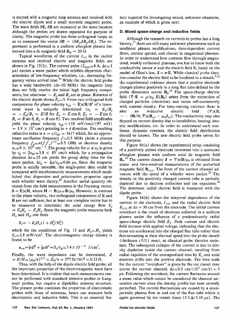
FIG. 15. Measurement of electromagnetic fields of a whistler wave. (a) Experimental setup showing wave excitation with an insulated magnetic loop antenna, propagation along a static magnetic field B,, and indepen- dent measurements of the electric field with the dipole probe and mag- netic fields with a magnetic probe. (b) Typical waveforms of the current I,,, through the exciter loop and the electric field Eytr) and magnetic field B,,,, at a distance AZ = 25 cm from the exciter. The current pulse excites a wave packet with decreasing tone vs time. i.e., the characteristic disper- sion of low-frequency whistlers. Point measurements of E and B yield the direction of wave propagation, the refractive index, hence plasma param- eters, and the energy flow and density of the wave.
Such measurements are performed at different afterglow times from which the decay of the electron temperature and the normalized ion drift speed are evaluated [Fig. 14(c)].
Having measured the ambipolar electric field (Fig. 11) and the ion drift speed (Fig. 14), the ion-neutral collision frequency y,, can be calculated from momentum balance, rniv,,,vd = eE. At t,-0.1 ms in the afterglow, one has Y,,Z 1. I X lo4 s - ‘. Such collisions of low temperature ions CkTi z kTJlO=O.l eV) are often dominated by charge- exchange processes which are difficult to measure other- wise.‘a The mean free path of a 0. l-eV argon ion is I = Vi/Y~n~ 6.3 cm (pc = 4 X 10 - 4 Tort-). LOW frequency ion acoustic waves such as shown in Fig. 13(a) are subject to strong collisional damping (v/w~O.2).
C. Inductive electric fields
Another useful application of the dipole probe is the measurement of rotational electric fields (V.E = 0, V XE = - &I/&). For a low frequency whistler wave, both electric and magnetic fields have been measured which yield the phase velocity U@, = E/B, direction of wave propagation and energy flow from the Poynting vector ExH, and plasma parameters (e$ or w,) via the refractive indexn* = (c/uph)* = 1 - c$/w(o - w,).‘~
Figure 15 (a) shows schematically how a whistler wave
is excited with a magnetic loop antenna and received with the electric dipole and a small movable magnetic probe. The wave fields SE, 6B are measured at the same location although the probes are drawn separated for purpose of clarity. The magnetic probe has three orthogonal loops, so as to measured the vector SB = (SB,,SB,,,SB,). The ex- periment is performed in a uniform afterglow plasma im- mersed into a dc magnetic field Be= = 20 G.
Typical waveforms of the current ICtj in the exciter antenna and received electric and magnetic fields are shown in Fig. 15(b). The current pulse (I,,,-4 A, At, 1 ps) excites a wave packet which exhibits dispersion char- acteristics of low-frequency whistlers, i.e., decreasing fre- quency versus arrival time.” While the electric field probe has a wide bandwidth (dc-20 MHz) the magnetic loop does not fully resolve the initial high frequency compo- nents, but otherwise - E,, and B, are in phase. Rotation of the electric dipole shows &E-O. From two orthogonal field components the phase velocity vph = EXB/B2 of a trans- verse wave is uniquely determined (u, = E,/B,,
-E/B, = E/Bfor E, = Ecostl, Ey = -Esin8, FX = B sin 8, B,, = B cos 0). Two resolved field amplitudes yield the phase velocity uph = (18 mV/cm)/(97 mG) = 1.9 X 10’ cm/s pointing in + z direction. The resulting refractive index is n = c/$h = 1617 which, for an approx- imate oscillation frequency f-O.5 MHz yields a plasma frequency fp-n(f f ,) “22: 8.5 GHz or electron density n,~9 X IO” cm - 3. The group velocity for w < w, is given by ug = 2Uph2:3.8 X 10’ cm/s which, for a propagation distance AZ-25 cm yields the group delay time for the wave packet, At, = A.&,-O.66 ,us. Since the magnetic probe is axially movable, the single-point data could be compared with interferometric measurements which estab- lished that dispersion and polarization properties agree with whistler wave theory.20 Another useful quantity ob- tained from the field measurements is the Poynting vector, S = EXH, where H = B/p=B/p,. However, in contrast to the phase velocity, two orthogonal components of E and B are not sufficient, but at least one complete vector has to be measured to determine the axial energy flow S, = EJY,, - Eflx. Since the magnetic probe measures both H, and H,,, one finds
S,= - Eflx( 1 + Hi/H;)
which for the conditions of Fig. 15 and H,,-H, yields S,-2.8 mW/cm’. The electromagnetic energy density is found to be
uc,,=feE2 + -&H2=Sz/vgY7.4x lo- ” J/cm3.
Finally, the wave impedance can be determined, 2 = E/H, (/LO/E) u2 = Zdn = 377 a/1617 = 0.23 R.
Thus, with the help of the dipole electric field probe, all the important properties of the electromagnetic wave have been determined. It is evident that such measurements can- not be performed with standard emissive probes or Lang- muir probes, but require a dipolelike antenna structure. The present probe combines the properties of electrostatic probes with those of antennas, hence can measure both electrostatic and inductive fields. This is an essential fea-
ture required for investigating mixed, unknown situations, an example of which is given next.
D. Mixed space-charge and inductive fields
Although the research on currents to probes has a long history,21 there are still many unknown phenomena such as nonlinear plasma modifications, time-dependent current flows, current spread, and closure in magnetized plasmas. In order to understand how currents flow through magne- tized, weakly collisional plasmas, one has to know both the conductivity tensor u and the electric field E, based on the model of Ohm’s law, J = WE. While classical probe theo- ries consider the electric field to be localized to a sheath,5’22 the experimental evidence shows that a positive electrode charges plasma positively in a long flux tube defined by the probe dimension across BeI The space-charge electric field (V*E = p/co, E.LBo) arises from the extraction of charged particles (electrons) and varies self-consistently with current density. For time-varying currents there is also an inductive electric field (VXEi = - aB/&, V XB,,) = pOJCt,). The conductivity may also depend on current density due to instabilities, heating, den- sity modifications, etc. In order to understand such non- linear, dynamic currents, the electric field distribution should be known. The new electric field probe serves for this purpose.
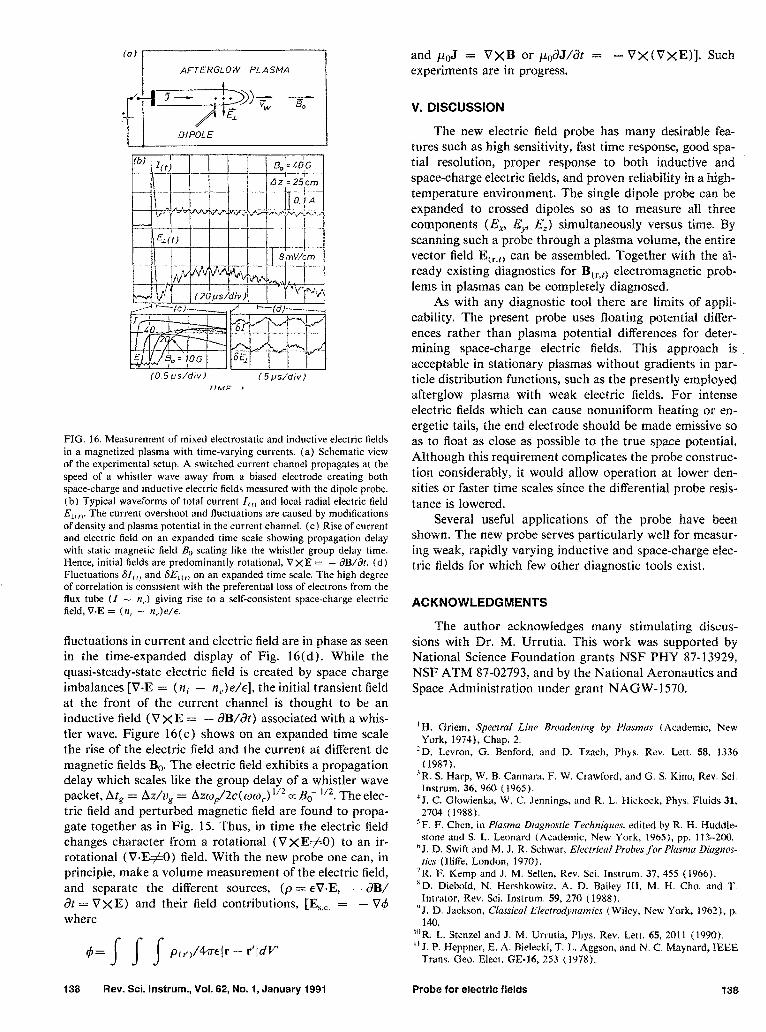
Figure 16(a) shows the experimental setup consisting of a positively pulsed electrode immersed into a quiescent afterglow plasma with uniform axial dc magnetic field BP” The current density J = VxB/pO is obtained from space- and time-resolved measurements of the perturbed magnetic field BC,,t). The front of the current channel ad- vances with the speed of a whistler wave packet.20 The density in the positively charged current tube is partially depleted due to electron collection and ion expulsion.‘4 The dominant radial electric field is measured with the dipole probe.
Figure 16(b) shows the temporal dependence of the current to the electrode, I(,), and the radial electric field ELCtj at AZ = 30 cm from the electrode. The initial current overshoot is the result of electrons collected in a uniform plasma under the influence of a predominantly radial space-charge electric field El. Peak current and electric field increase with applied voltage, indicating that the elec- trons are accelerated into the charged flux tube rather than free-streaming at their thermal speed into the probe sheath (thickness s SO.1 mm), as classical probe theories main- tain. The subsequent collapse of the current is due to den- sity depletion inside the current channel, resulting from radial expulsion of the unmagnetized ions by EL and axial electron drifts into the positive electrode. The time scale for the current “overshoot” is given by the ion transit time across the current channel, At-O.5 cm/( lo5 cm/s) = 5 ps. Following the overshoot, the current fluctuates around a mean value which cannot be considered the classical sat- uration current since the density profile has been severely perturbed. The current fluctuations are caused by a quasi- periodic plasma flow in and out of the flux tube which is again governed by ion transit times (5 <, At 5 10 ys). The
137 Rev. Sci. Instrum., Vol. 62, No. 1, January 1991 Probe for electric fields 137
(0) AFTERGLOW PLASM4
pz!Ipp~ Tg-
I DiPOL E
(0.5/.is/div) (5pddiv) TlMF ,
FIG. 16. Measurement of mixed electrostatic and inductive electric fields in a magnetized plasma with time-varying currents. (a) Schematic view of the experimental setup. A switched current channel propagates at the speed of a whistler wave away from a biased electrode creating both space-charge and inductive electric fields measured with the dipole probe. (b) Typical waveforms of total current I,,, and local radial electric field E t(,,. The current overshoot and fluctuations are caused by modifications of density and plasma potential in the current channel. (cl Rise of current and electric field on an expanded time scale showing propagation delay with static magnetic field S,, scaling like the whistler group delay time. Hence, initial fields are predominantly rotational, V)(E = - aB/&. (d) Fluctuations Sit,, and 6E,,,, on an expanded time scale. The high degree of correlation is consistent with the preferential loss of electrons from the flux tube (1 - n,) giving rise to a self-consistent space-charge electric field, V*E = (n, - n,)e/e.
fluctuations in current and electric field are in phase as seen in the time-expanded display of Fig. 16(d). While the quasi-steady-state electric field is created by space charge imbalances [V-E = (ni - n,)e/‘c], the initial transient field at the front of the current channel is thought to be an inductive field (VXE = - dB/&) associated with a whis- tler wave. Figure 16(c) shows on an expanded time scale the rise of the electric field and the current at different dc magnetic fields BO. The electric field exhibits a propagation delay which scales like the group delay of a whistler wave packet, his = AZ/V, = Azw~~c~~ww,) I’* a B& “2. The elec- tric field and perturbed magnetic field are found to propa- gate together as in Fig. 15. Thus, in time the electric field changes character from a rotational (V xE#O) to an ir- rotational (V.E#O) field. With the new probe one can, in principle, make a volume measurement of the electric field, and separate the different sources, (p = eV.E, - dB/ dt = VXE) and their field contributions, [E,,,, = - VC$ where
4=sss pcit/4mjr -- r’[dV’
and j.+I = VxB or p,aJ/& = - Vx(VxE)]. Such experiments are in progress.
v. DISCUSSIQN The new electric field probe has many desirable fea-
tures such as high sensitivity, fast time response, good spa- tial resolution, proper response to both inductive and space-charge electric fields, and proven reliability in a high- temperature environment. The single dipole probe can be expanded to crossed dipoles so as to measure all three components (E,, E,,, E,) simultaneously versus time. By scanning such a probe through a plasma volume, the entire vector field EC,,t, can be assembled. Together with the al- ready existing diagnostics for Bt,,f) electromagnetic prob- lems in plasmas can be completely diagnosed.
As with any diagnostic tool there are limits of apph- cability. The present probe uses floating potential differ- ences rather than plasma potential differences for deter- mining space-charge electric fields. This approach is acceptable in stationary plasmas without gradients in par- ticle distribution functions, such as the presently employed afterglow plasma with weak electric fields. For intense electric fields which can cause nonuniform heating or en- ergetic tails, the end electrode should be made emissive so as to float as close as possible to the true space potential. Although this requirement complicates the probe construc- tion considerably, it would allow operation at lower den- sities or faster time scales since the differential probe resis- tance is lowered.
Several useful applications of the probe have been shown. The new probe serves particularly well for measur- ing weak, rapidly varying inductive and space-charge elec- tric fields for which few other diagnostic tools exist.
ACKNOWLEDGMENTS
The author acknowledges many stimulating discus- sions with Dr. M. Urrutia. This work was supported by National Science Foundation grants NSF PHY 87-13929, NSF ATM 87-02793, and by the National Aeronautics and Space Administration under grant NAGW-1570.
‘II. Griem, Spectral Line Broadening by Plasmas (Academic, New York, 1974), Chap. 2.
‘D. Levron, G. Benford, and D. Tzach, Phys. Rev. Lett. 58. 1336 (1987).
“R. S. Harp, W. El. Cannara, F. W. Crawford, and G. S. Kino, Rev. Sci. Instrum, 36, 960 (1965).
‘J, C. Glowienka, W. C. Jennings, and R. L. Hickock, Phys. Fluids 31, 2704 (1988).
“F. F. Chen, in Plasma Diagnostic Techniques, edited by R. H. Huddle- stone and S. L. Leonard (Academic, New York, 1965), pp. 113-200.
hJ. D. Swift and M. J. R. Schwar, Electrical Probes for Plasma Diagnos- tics (Iliffe, London, 1970).
‘R. F. Kemp and J. M. Sellen, Rev. Sci. Instrum. 37, 455 f 1966). ‘D. Diebold, N. Hershkowitz, A. D. Bailey III, M. H. Cho, and T.
Intrator, Rev. Sci. Instrum. 59, 270 (1988). “J. D. Jackson, Classical Electrodynamics (Wiley. New York, 19621, p.
140. “‘R. L. Stenzel and J. M. Urrutia, Phys. Rev. Lett. 65, 2011 (1990j, ‘t J P Heppner, E. A. Bielecki, T. L. Aggson, and N. C. Maynard, IEEE
Trans. Geo. Elect. GE-16, 253 (1978).
138 Rev. Sci. Instrum., Vol. 62, No. 1, January 1991 Probe for electric fields 138

“R. L. Stenzel, W. Gekelman, and N. Wild, .I. Geophys. Res. 87, 111 (1982).
‘“R. L. Stenzel and W. F. Daley, U. S. Patent No. 4,216,405 (1980). “R. L. Stenzel and J. M. Urrutia, J. Geophys. Res. 95, 6209 (1990). “J. M. Urrutia and R. L. Stenzel, Phys. Rev. Lett. 57, 715 (1986). lbR. L. Stenzel and J. M. Urrutia, Geophys. Res. Lett. 16, 361 (1989). “R. K. Wangsness, Electromagnetic Fields (Wiley, New York, 1986), p.
256. ‘“S. C. Brown, Basic Data of Plasma Physics, 1966 (MIT Press, Cam-
bridge, 1967). 19R. A. Helliwell, Whistlers and Related Ionospheric Phenomena (Stan-
ford Univ. Press, Stanford, 1965), Chap. 1. *‘J. M. Urrutia and R. L. Stenzel, Phys. Rev. Lett. 62, 272 (1989). 2’1 Langmuir, in Collected Works of Irving Langmuir, edited by C. G.
’ Suits (Pergamon, New York, 1961), Vols. 3-5. 22L. Schott, in Plasma Diagnostics, edited by W. Lochte-Holtgreven
(Wiley, New York, 1968), Chap. 11.
139 Rev. Sci. Instrum., Vol. 62, No. 1, January 1991 Probe for electric fields 139