A New Post-Collimation Trimmer for Neutron …accelconf.web.cern.ch/AccelConf/c98/papers/a-29.pdfW ~...
4
A NEW POST-COLLIMATION TRIMMER FOR NEUTRON THERAPY AT N AC A. MULLER, H.N. JUNGWIRTH, A.N. SCHREUDER, H.A. SMIT AND F.M. SMITH National Accelerator Centre, P. O. Box 72, Faure 7131, South Africa The versatility of the isocentric system for neutron therapy at the National Accelerator Centre (NAC) has been dramatically improved by the provision of more flexible beam shaping . This was achieved by commissioning a new and economical multi - leaf post-collimation trimmer designed and constructed in-house. The inexpensive trimmer consists of two sets of sixteen iron plates, which are moved by a single air-driven actuator against a simple and cheap wooden insert made to define each new field profile. The mechanical layout and pneumatic design as well as the simple manual control system of this device are presented. 1 Introduction A total of 945 patients have been treated in various clin- ical trials on the NAC p(66)/Be(40) isocentric neutron therapy facility [1] up to March 1998. In addition to the existing treatment protocols, a new protocol for the treatment of prostate cancer with fast neutrons is be- ing formulated at NAC following recent evidence from clinical trials which demonstrated the efficacy of con- formal field shaping in reducing patient morbidity [2,3]. Existing means of beam shaping, which employed 12 cm thick tungsten blocks and custom made steel blocks, was considered inadequate to provide the field shaping re- quired by this new protocol. Experimental investigations showed, however, that a multi-leaf post collimator device could be used effectively [4]. The multi-leaf trimmer had to be added to our ex- isting neutron therapy unit NT66R-490 from Elven Pre- cision (see figure 1), which was installed in 1985. The new device replaces the original gamma-shutter assem- bly, and it should fit into the contour of the existing hood, with restricted space particularly towards the iso- centre. An area of 150 x 150 mm 2 for field shaping was requested, with the possibility to revert to the full square field of 290 x 290 mm 2 whenever necessary. On each side, sixteen leaves of chemically pure iron were specified, each 10 mm thick and 150 mm high, and the whole unit had to be rotatable through 360 degrees. An additional layer of 50 mm thick borated polyethylene shielding material had to fit between the existing rectangular jaw collima- tor and the new multi-leaf trimmer. To contain costs, the trimmer configuration had to be simple and to allow for manufacture in our workshop. 2 Design Concept After some preliminary tests, the configuration shown in figure 2 was chosen. The sixteen iron plates on each side form two leaf-packs held in rectangular open frames, Figure 1: Arrangement on the neutron therapy gantry. in which they can slide with one degree of freedom. These frames move radially in opposite direction, so that the aligned plates meet at the centerline on the inward stroke. A pressed-wood "core" insert, representing the projected shape of the area to be treated, can be placed centrally in the path of the plates. Hence, on moving the frames inward, those plates which come into contact with the core are stopped and a cavity is formed around the insert. At the end of the inward stroke, the plates are clamped so that the shape of the cavity is preserved. For this process to function properly, the friction be- tween the plates and the frame must be greater than the friction between adjoining plates. Consequently, this setting-up operation can only be done when the beam axis is vertical, either up or down . The clamped leaf- packs are then opened a short distance, so that the in- sert can be removed, and afterwards are closed again. Proceedings of the 15th International Conference on Cyclotrons and their Applications, Caen, France 119
Transcript of A New Post-Collimation Trimmer for Neutron …accelconf.web.cern.ch/AccelConf/c98/papers/a-29.pdfW ~...

A NEW POST-COLLIMATION TRIMMER FOR NEUTRON THERAPY AT N AC
A. MULLER, H.N. JUNGWIRTH, A.N. SCHREUDER, H.A. SMIT AND F.M. SMITH
National Accelerator Centre, P. O. Box 72, Faure 7131, South Africa
The versatility of the isocentric system for neutron therapy at the National Accelerator Centre (NAC) has been dramatically improved by the provision of more flexible beam shaping . This was achieved by commissioning a new and economical multi- leaf post-collimation trimmer designed and constructed in-house. The inexpensive trimmer consists of two sets of sixteen iron plates, which are moved by a single air-driven actuator against a simple and cheap wooden insert made to define each new field profile. The mechanical layout and pneumatic design as well as the simple manual control system of this device are presented.
1 Introduction
A total of 945 patients have been treated in various clinical trials on the NAC p(66)/Be(40) isocentric neutron therapy facility [1] up to March 1998. In addition to the existing treatment protocols, a new protocol for the treatment of prostate cancer with fast neutrons is being formulated at NAC following recent evidence from clinical trials which demonstrated the efficacy of conformal field shaping in reducing patient morbidity [2,3]. Existing means of beam shaping, which employed 12 cm thick tungsten blocks and custom made steel blocks, was considered inadequate to provide the field shaping required by this new protocol. Experimental investigations showed, however, that a multi-leaf post collimator device could be used effectively [4].
The multi-leaf trimmer had to be added to our existing neutron therapy unit NT66R-490 from Elven Precision (see figure 1), which was installed in 1985. The new device replaces the original gamma-shutter assembly, and it should fit into the contour of the existing hood, with restricted space particularly towards the isocentre. An area of 150 x 150 mm 2 for field shaping was requested, with the possibility to revert to the full square field of 290 x 290 mm 2 whenever necessary. On each side, sixteen leaves of chemically pure iron were specified, each 10 mm thick and 150 mm high, and the whole unit had to be rotatable through 360 degrees. An additional layer of 50 mm thick borated polyethylene shielding material had to fit between the existing rectangular jaw collimator and the new multi-leaf trimmer. To contain costs, the trimmer configuration had to be simple and to allow for manufacture in our workshop.
2 Design Concept
After some preliminary tests, the configuration shown in figure 2 was chosen. The sixteen iron plates on each side form two leaf-packs held in rectangular open frames,
Figure 1: Arrangement on the neutron therapy gantry.
in which they can slide with one degree of freedom. These frames move radially in opposite direction, so that the aligned plates meet at the centerline on the inward stroke. A pressed-wood "core" insert, representing the projected shape of the area to be treated, can be placed centrally in the path of the plates. Hence, on moving the frames inward, those plates which come into contact with the core are stopped and a cavity is formed around the insert. At the end of the inward stroke, the plates are clamped so that the shape of the cavity is preserved.
For this process to function properly, the friction between the plates and the frame must be greater than the friction between adjoining plates. Consequently, this setting-up operation can only be done when the beam axis is vertical, either up or down . The clamped leafpacks are then opened a short distance, so that the insert can be removed, and afterwards are closed again.
Proceedings of the 15th International Conference on Cyclotrons and their Applications, Caen, France
119

~--------W TA. RGET
I
Figure 2: Schematic layout of the multi-leaf trimmer.
Finally, the trimmer must be turned into the correct an-
A double-acting pneumatic cylinder rotates a central drive-gear which meshes with two idler gears. These idler gears each drive a rack which is mounted on the leaf-pack carriage . The two racks are arrayed 180 degrees around the centre of the drive-gear, thus moving the carriages simultaneously in opposite direction. The two leaf-packs have a stroke of 76 mm each, but the outward movement is restricted to only 1 mm before the insert is released for removal. This is done by means of a ratchet, which is automatically pushed into the path of a pin mounted on the drive gear as soon as the coreholder is installed (see figure 4) . The core-holder for the full field of 290x290 mm2 has a cut-out which prevents the stop from being activated .
gular position and locked. The gantry is now ready to Ratchet
be rotated into position for treatment. Pin
After treatment, the gantry has to be rotated into vertical position again, and the frames are unclamped and moved out against two stops, so that the plates on each side are re-aligned for starting a new cycle. The Core-holder
stopper bars provided for this purpose must be easily re- with cut -out
movable, so that the plates can be moved out far enough for the full square field of 290x290 mm2 to be used. Figure 4: Backstop for removal of core insert.
3 Mechanical Configuration
3.1 Drive system
We investigated a variety of drive systems utilising A.C . or stepping motors, a pneumatic actuator, and even one based on hand operation. A solution using gears driven by an air cylinder as shown in figure 3 was chosen for its simplicity, low cost and ease of operation.
I [-AF - PACK I I~AME
t;dl ~~~ r I)NI UMAl Ie I CYI IND[R
DRIVE GEAR IDLER GEAR
RACK
Figure 3 : Schemat ic representation of the drive system .
3.2 Leaf-pack structure and clamping mechanism
As is shown in figure 5, the leaf-pack is supported by a frame mounted permanently on linear ball-bearings which are carried by the gearbox. The leaf-pack is installed on the support frame using only two screws and a locating pin, thus making the exchange of leaf-packs a quick and easy operation. This may be necessary if their activation becomes too high . The removed leaf-packs can then be stored to cool down to acceptable radiation levels for re-use .
The leaf-pack frame is built up from 20 mm stainless steel plates machined all round. The leaves are ground to a surface finish of l.6 /-Lm and to a thickness of 10 ± 0.03 mm. After grinding, the leaves are first electroless nickel-plated and then heat treated for 5 hours at 350°C. This process provides protection against corrosion and also a significant reduction in the friction coeffi cient. Each leaf is fitted with a pin at the outside edge of the plate to prevent it from accidentally falling out of the fr ame .
To determine the correct force needed for clamping
Proceedings of the 15th International Conference on Cyclotrons and their Applications, Caen, France
120
SU PPORTFRAM E LEAF - PACK
PNEUMATIC
LEAF CLAMP
Figure 5: Layout of the leaf-pack and its support structure.
the leaves, we used a specially made testing tool. These tests showed that the clamping force has to be at least 2200 N for safe operation. To achieve such a force within the confined space available, we use two compression springs of 200 N each, pressing onto a pin with a ratio of 6.4, thus producing a clamping force of 2560 N. To allow the leaves to slide, we have to release the clamping force. This is done with a single-acting pneumatic clamping module of rectangular shape, which is positioned in line with the springs and exerts a force of 500 N at 6 bar air pressure.
3.3 Mounting frame and rotating structure
The mounting frame is shown in figure 6 and consists of a central stiffening structure with two side plates to provide the near-circular shape required for the rotational bearing. This bearing is made up from six equi-spaced groups of three ball-bearings each, two for axial location and one for radial positioning . The circular bearing rail, on which the whole assembly can be rotated, is mounted on four pedestals which fit the holes left by the removed gamma shutter. A cam-operated clamp locks the trimmer assembly in the required angular position on the rail.
PLATE
PNlU MATI C CONTRO L U".JiT AND PAN EL MOU NTING FRAME
Figure 6: Mounting frame and installation.
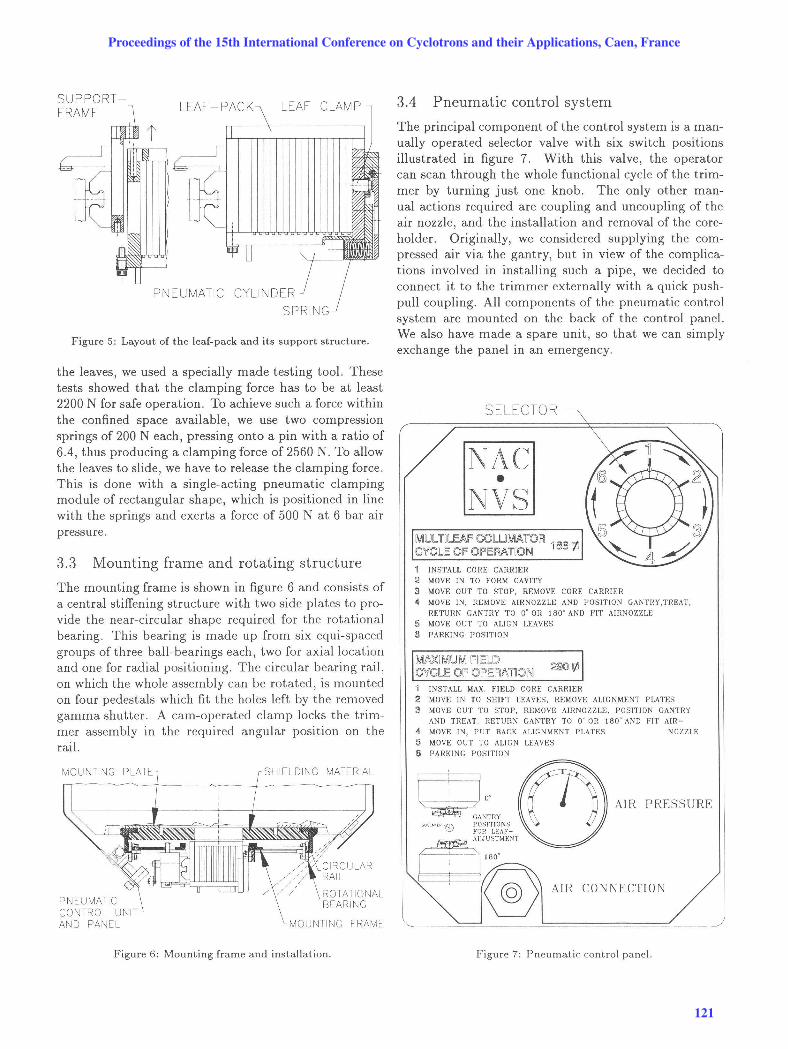
3.4 Pneumatic control system
The principal component of the control system is a manually operated selector valve with six switch positions illustrated in figure 7. With this valve, the operator can scan through the whole functional cycle of the trimmer by turning just one knob. The only other manual actions required are coupling and uncoupling of the air nozzle, and the installation and removal of the coreholder . Originally, we considered supplying the compressed air via the gantry, but in view of the complications involved in installing such a pipe, we decided to connect it to the trimmer externally with a quick pushpull coupling. All components of the pneumatic control system are mounted on the back of the control panel. We also have made a spare unit, so that we can simply exchange the panel in an emergency.
SELECTOR
MllDl UJEAF COl UIMA r OPl 100!tl C'1fClE Of OIF'EM nON
INSTALL CORE CARRIER 2 MOVE IN TO FORM CAVITY
3 MOVE OUT TO STOP. REMOVE CORE CARRIER 1\ MOVE IN. REMOVE AIRNOZZLE AND POSITION GANTRY,TREAT,
HETURN GANTRY TO 0" OR I BO" AND FIT AIRNOZZLE
5 MOVE OUT TO ALIGN LEAVES
!l PARKING POSITION
MAXIMUM IFIIEW C'1fCU; OIF OIPEM~110N 1 INSTALL MAX. FIELD CORE CARRIER
2 MOVE IN TO SHIrT LEAVES. REMOVE ALIGNMENT PLATES 3 MOVE OUT TO STOP, REMOVE AIRNOZ ZLF., POSITION GANTRY
AND THEAT. RETURN GANTRY TO 0 " Oil 180" AND rTr AIH-
1\ MOVE IN, PUT BACK AI.lGNMENT PLATES
5 MOVE OUT TO ALIGN LEAVES
16 PARKING POSITION
NOZZLE
AIR PRESS URE
AJH CONNECTION
~~~-----~------- .. ~-- -- -- ---
Figure 7: Pneumatic control panel.
Proceedings of the 15th International Conference on Cyclotrons and their Applications, Caen, France
121

4 Assembly and Installation
4.1 Manufacture and assembly
Manufacture of all components was done in our mechanical workshop, except the surface grinding and nickelplating of the leaves, which were contracted out to specialised companies. No problems out of the ordinary were encountered at any fabrication stage.
The initial assembly of the trimmer was done on a special frame , thus enabling us to test all its functions before installation on the gantry. At this stage, we also extensively involved personnel of our medical radiation group, so that they could familiarize themselves with the operation of the trimmer and make suggestions for improvements.
The attachment for positioning the core-holder plate was modified to save space towards the isocentre. A quick-release mechanism for the two leaf alignment bars was incorporated, and saftey guards were added to cover them. Down-stream from the trimmer, a ring-shaped plate was installed, with mounting pads for the original tungsten blocks needed when treating large field areas. A cut-out in this plate allows the laser beam for patient alignment to pass through to the isocentre.
A further modification was introduced on the guide system of the leaf-pack frames. These frames were originally supported by the ball guides only, but this was found not to be rigid enough. An additional support bearing was provided on the opposite side, which runs in a straight guide rail.
4.2 Installation
The installation of the trimmer went as planned, except for the need to fit a counterweight, so that the unit could also be rotated eas ily with the gantry axis in a horizontal position. The scale indicating the angular position of the trimmer was also relocated, so that it could be read off more easily. Part of the gantry hood had to be cut away and new mounting brackets were made for it.
5 Operational Results
The versatility of our isocentric gantry for neutron therapy was dramati cally improved by the provision of more fl exible beam shaping with the new multi-leaf t.rimmer. Figure 8 shows the t.rimmer set up for a treatment session. Although the trimmer is in use since July 1997, all it.s capabiliti es are not fully exploited yet, because the existing treatment planning program cannot fully accommodate multi-leaf collim ators .
After about 5 months of operation , it was found that. t.he clamping force was no longer sufficient, and t.he leaves
started to slide when the gantry turned through the horizontal position . Resetting the clamping pins proved to be a simple matter, however, and the trimmer now functions without any problem.
Figure 8: The multi-leaf trimmer set up for treatment.
Acknowledgments
The authors want to thank the personnel of the medical radiation group for their enthusiastic support and cooperation in this project. We are also grateful to the staff of our mechanical workshop for the high quality of their work, and to Mr W.A.G. Nel for compiling this paper.
References
[1] D.T.L. Jones, A.N. Schreuder, J.E. Symons and M Yudelev, "The NAC Particle Therapy Facilities", H adronthempy in Oncology, 1994; 307.
[2] M. Austin-Seymour et al., "Impact of a multi-leaf collimator on treatment morbidity in localised carcinoma of the prostate", Int. J. Radiat. Oncol. Bioi. Phys. , 1994; 30:1065-1071.
[3] T.W. Griffin, G.E. Laramore, "Neutron radiation and prostate cancer", Int. J. Radiat. Oneol. Bioi. Phys., 1995; 33:231-232.
[4] D.T.L. Jones et al., "Experimental Investigations of a Multiblade Trimmer for Neutron Therapy" , Journal of Braehytherapy Int 'l, 1997; 13:59-66.
Proceedings of the 15th International Conference on Cyclotrons and their Applications, Caen, France
122