
A new method for crankpin bearing fault diagnosis … new method for crankpin bearing fault...
13
A new method for crankpin bearing fault diagnosis based on dynamic pressure simulation and condition monitoring JINJIE ZHANG*, ZHINONG JIANG, YINAN XIE, NA LU Diagnosis and Self-Recovery Engineering Research Center Beijing University of Chemical Technology P.O. Box. No. 130, NO.15 of North Third Ring Road, Beijing 100029 P.R. CHINA [email protected] Abstract: - Connecting rod is a crucial part of the reciprocating compressor and the crankpin bearing fault of connecting rod is always the obstacle in fault diagnosis. Normally the condition monitoring of connecting rod and dynamic analysis are based on cylinder dynamic pressure monitoring which is also an important method for fault diagnosis. However, it is hard to diagnose crankpin bearing fault in realistic when it comes to the reciprocating compressor unfit for installing pressure transducers because there is no indicator hole or the pressure is too high. In this paper, a new method is presented to deal with above problems. The theoretical three-dimensional models of cylinder and valves of the experiment platform are established to finish the numerical simulation of dynamic pressure which has been compared with the actual measured dynamic pressure signals. Dynamic analysis of crankpin bearing with actual fault is applied to find out the abnormal impact phases. Contrasting results show that actual vibration impact phases are consistent with those of theoretical calculation. The realistic fault maintenance finally confirms the effectiveness of the new method. Key-Words: - Connecting rod; Reciprocating compressor; Crankpin bearing; Numerical simulation; Dynamics analysis 1 Introduction Reciprocating compressor is the crucial equipment of process industry such as refining, pipeline and chemical engineering [1]. Significant accidents happen frequently due to structure complexity and numerous vibration sources within low accuracy rate of fault diagnosis. How to improve the accuracy of fault diagnosis of reciprocating compressor always confuse the operators in keeping the compressor in good operating condition. Nowadays, an increasing number of reciprocating compressors have installed the on-line monitoring systems to monitor the faults as leakage of valve, abrasion of supporting ring, loosening of the piston rod locknut as well as fracture of piston rod. But there are few remarkable improvements of crankpin bearing fault diagnosis. Connecting rod connects with crankpin and crosshead respectively transferring rotation into reciprocation and transmitting torque from crankshaft. It is difficult to install the transducers on connecting rod as it does not contact with compressor’s body. Abrasion of crankpin bearing, a common fault of connecting rod, will lead to Babbitt Metal abrasion at the early stage and result in lubricating oil pressure dropping. It is much likely to induce abrasion of main bearings, even fracture of the connecting rod bolt or crankshaft. Traditional crankpin bearing fault diagnosis is based on the real-time monitoring of cylinder dynamic pressure because the actual crankpin bearing working state is closely related to the load condition of the compressor and the mass of moving components. So it cannot conduct fault diagnosis effectively until acquire the data of the real-time operating condition of reciprocating compressor. When it comes to the reciprocating compressors with too high pressure or without indicator holes, operators cannot install dynamic pressure sensors and have no access to get the cylinder dynamic pressure signals. As a result, it is hard to diagnose connecting rod faults as bearing abrasion of crankpin bearing, fracture of connecting rod bolt, which have bad influences on enterprise security and steady production. Most researchers paid attention to the field of intelligent diagnosis algorithms and feature extraction. Support vector machines, neural networks and other methods have been used in fault feature extraction and classification of reciprocating compressor and motor [2-5]. The actual faults diagnosis researches are inclined to take advantage of indicator diagram [4, 6, 7]. Structure dynamic and fault analysis of reciprocating machine mainly concentrates on small compressors and the engines WSEAS TRANSACTIONS on SYSTEMS Jinjie Zhang, Zhinong Jiang, Yinan Xie, Na Lu E-ISSN: 2224-2678 614 Issue 12, Volume 12, December 2013
Transcript of A new method for crankpin bearing fault diagnosis … new method for crankpin bearing fault...

A new method for crankpin bearing fault diagnosis based on dynamic pressure simulation and condition monitoring
JINJIE ZHANG*, ZHINONG JIANG, YINAN XIE, NA LU Diagnosis and Self-Recovery Engineering Research Center
Beijing University of Chemical Technology P.O. Box. No. 130, NO.15 of North Third Ring Road, Beijing 100029
P.R. CHINA [email protected]
Abstract: - Connecting rod is a crucial part of the reciprocating compressor and the crankpin bearing fault of connecting rod is always the obstacle in fault diagnosis. Normally the condition monitoring of connecting rod and dynamic analysis are based on cylinder dynamic pressure monitoring which is also an important method for fault diagnosis. However, it is hard to diagnose crankpin bearing fault in realistic when it comes to the reciprocating compressor unfit for installing pressure transducers because there is no indicator hole or the pressure is too high. In this paper, a new method is presented to deal with above problems. The theoretical three-dimensional models of cylinder and valves of the experiment platform are established to finish the numerical simulation of dynamic pressure which has been compared with the actual measured dynamic pressure signals. Dynamic analysis of crankpin bearing with actual fault is applied to find out the abnormal impact phases. Contrasting results show that actual vibration impact phases are consistent with those of theoretical calculation. The realistic fault maintenance finally confirms the effectiveness of the new method. Key-Words: - Connecting rod; Reciprocating compressor; Crankpin bearing; Numerical simulation; Dynamics analysis 1 Introduction
Reciprocating compressor is the crucial equipment of process industry such as refining, pipeline and chemical engineering [1]. Significant accidents happen frequently due to structure complexity and numerous vibration sources within low accuracy rate of fault diagnosis. How to improve the accuracy of fault diagnosis of reciprocating compressor always confuse the operators in keeping the compressor in good operating condition.
Nowadays, an increasing number of reciprocating compressors have installed the on-line monitoring systems to monitor the faults as leakage of valve, abrasion of supporting ring, loosening of the piston rod locknut as well as fracture of piston rod. But there are few remarkable improvements of crankpin bearing fault diagnosis. Connecting rod connects with crankpin and crosshead respectively transferring rotation into reciprocation and transmitting torque from crankshaft. It is difficult to install the transducers on connecting rod as it does not contact with compressor’s body. Abrasion of crankpin bearing, a common fault of connecting rod, will lead to Babbitt Metal abrasion at the early stage and result in lubricating oil pressure dropping. It is much likely to induce abrasion of main bearings, even fracture of the connecting rod bolt or crankshaft. Traditional
crankpin bearing fault diagnosis is based on the real-time monitoring of cylinder dynamic pressure because the actual crankpin bearing working state is closely related to the load condition of the compressor and the mass of moving components. So it cannot conduct fault diagnosis effectively until acquire the data of the real-time operating condition of reciprocating compressor.
When it comes to the reciprocating compressors with too high pressure or without indicator holes, operators cannot install dynamic pressure sensors and have no access to get the cylinder dynamic pressure signals. As a result, it is hard to diagnose connecting rod faults as bearing abrasion of crankpin bearing, fracture of connecting rod bolt, which have bad influences on enterprise security and steady production.
Most researchers paid attention to the field of intelligent diagnosis algorithms and feature extraction. Support vector machines, neural networks and other methods have been used in fault feature extraction and classification of reciprocating compressor and motor [2-5]. The actual faults diagnosis researches are inclined to take advantage of indicator diagram [4, 6, 7]. Structure dynamic and fault analysis of reciprocating machine mainly concentrates on small compressors and the engines
WSEAS TRANSACTIONS on SYSTEMS Jinjie Zhang, Zhinong Jiang, Yinan Xie, Na Lu
E-ISSN: 2224-2678 614 Issue 12, Volume 12, December 2013

[8-12]. Some researchers focus on the working principle and efficiency of the mechanism systems. Different theoretical analysis models have been built to make optimizations [13-15]. The research on the dynamic analysis of connecting rod most focuses on the engine and short compressor, concentrating on the effect of the oil film properties , structure optimization,failure analysis of the connecting rod with different methods [16-19]. Today, computer technology has been widely used in various industries [20-22]. The alarm methods and fault diagnosis expert system have been presented to improve the lever of the reciprocating compressor fault diagnosis [23, 24].
However there are no records about research of reciprocating compressor crankpin bearing fault diagnosis based on simulated dynamic pressure from
above literatures. In this paper, we focus on the need for diagnosing
the crankpin bearing fault and a new method based on cylinder dynamic pressure simulation has been presented. In order to solve the difficulties, this new method simulates reciprocating compressor cylinder dynamic pressure with thermodynamics study to analyze the forces on the connecting rod and captures the early feature of crankpin bearing fault based on the actual operating parameters and structure parameters. This method has positive effect on the reciprocating compressor connecting rod fault diagnosis: dynamic pressure transducers needless, low cost of fault monitoring, no risks aroused by processing indicator holes or installing dynamic pressure transducers.
Nomenclature a acceleration (m/s2) Subscripts f the friction force (N) pis the piston F force (N) pis-in inside of the piston L length of connecting rod (m) pis-out outside of the piston M mass (kg) rod the piston rod N rotate speed of crank (r/min) vp the valve plate p pressure (Pa) cb the crankpin bearing R radius of crank (m) cro the crosshead S area (m2) cy-in inside of the cylinder t time (s) cy-out outside of the cylinder v reciprocating motion speed (m/s) con the connecting rod x displacement (m) pin the crosshead pin cb-x direction along the X-axis on the crankpin Greek letters cb-y direction along the Y-axis on the crankpin ω angular speed of crank (rad/s) cb-cf direction from crankpin to crankshaft
α the angle between the connecting rod and the positive direction of the X-axis cb-con direction from connecting rod to crankpin
β the angle between the direction of the force on the crankpin bearing and the positive direction of the X axis
con-re the part takes reciprocating motion of connecting rod
θ the angle between the crank and the negative direction of the X-axis con-ro the part takes rotary motion of connecting
rod
δ the angle between the direction of the force on the crankpin bearing and the positive direction of the X'-axis
pin-x direction along the X-axis on the crosshead pin
λ the ratio of the crank radius and connecting rod length pin-y direction along the Y-axis on the crosshead
pin 2 Theoretical simulation of dynamic pressure
Different from other researches on cylinder dynamic pressure numerical simulation which are based on mathematical modeling, the paper applies the CFD software: FLUENT software, to simulate
the pressure in the whole reciprocating process. FLUENT software has been used in the flow analysis of valves and design of the reciprocating compressor, but seldom in fault diagnosis [25, 26]. Compared with mathematical models, the FLUENT software has several advantages:
WSEAS TRANSACTIONS on SYSTEMS Jinjie Zhang, Zhinong Jiang, Yinan Xie, Na Lu
E-ISSN: 2224-2678 615 Issue 12, Volume 12, December 2013

It has lower theoretical error than mathematic models when modeling the valve and the flow structure of reciprocating compressor.
It can realize parametric modeling when simulating theoretical dynamic pressure of different compressor structure and different working condition parameters.
2.1 The simulation object
The simulation and analysis object is a 2D type reciprocating compressor which is single stage and drove by motor. The parameters of the compressor are shown in Table 1 and the compressor is shown in Fig.1. In production process, the compressor has been drilled the indicator holes to install the dynamic pressure transducers which can monitor the pressure of the cylinder. As a result, we can compare the simulation pressure signals with the actual signals.
Table 1 The operation parameters of the reciprocating compressor
Operating parameters Value Operating parameters Value Working speed 495r/min Crank radius 0.09m Connect rod length 0.45m Cylinder radius 0.125m Clearance volume 0.001269m3 Rated discharge volume 12 m3/min The suction pressure 100KPa The discharge pressure 200/300KPa The suction temperature 27℃ The discharge temperature 90℃ The suction valve equivalent stiffness 8000N/m The discharge valve equivalent
stiffness 6000N/m
The spring pre-compression of suction valve 0.004m The spring pre-compression of
discharge valve 0.004m
The displacement of suction valve plate 0.002m The displacement of discharge valve
plate 0.002m
The suction valve number in one side of the cylinder 2 The discharge valve number in one
side of the cylinder 2
Fig.1 The reciprocating compressor 2.2 The simulation models
This compressor is comprised with two cylinders which have the same structure and working stage. As a result, we can only build the model of one cylinder and its valves to simulate the dynamic pressure of the compressor. The geometry model of flow structure in the valve and cylinder is shown in Fig.2. Some simplifications are made as follows: Leakages in valve are neglected in the model. The valve flow channel is simplified with no
rounding, which is more convenient for meshing.
Because of the symmetrical characteristic, the model is half built to reduce the computational effort.
Fig.2 The geometry model of valves and cylinder
In CFD analysis, the mesh quality directly affects
the calculation accuracy and convergence rate. The valve model was separated in three parts in order to apply structured hexahedral mesh because the hexahedral mesh has the best effect in all kinds of meshes. As we separated the model, we need to set the contact property of the three parts as INTERFACE to ensure that the parts will communicate with each other. In addition, we apply
WSEAS TRANSACTIONS on SYSTEMS Jinjie Zhang, Zhinong Jiang, Yinan Xie, Na Lu
E-ISSN: 2224-2678 616 Issue 12, Volume 12, December 2013

the unit which interval size is 0.002m to mesh the cylinder because the size of the cylinder is larger than others meshed with the unit which interval size is 0.001m. The final number of grids is 1132880. The mesh model of the flow structure is shown in Fig.3. 2.3 Dynamic mesh and boundary conditions
During the operation of reciprocating compressor, the valve plate will moves frequently and the volume of the cylinder will be changed by reciprocating movement of piston. Dynamic mesh is used to simulate the motions of the piston. Three mesh schemes are adopted: soothing, layering and remeshing. The motion of the valve plate and piston are complex and need to use UDF to define the motions. 2.3.1 Dynamic mesh of the cylinder part
Fig.3 The mesh model of the flow structure
MrodMcro
Mcon
α θ
Mpis
x
L R
pis
Fig.4 Structure of moving parts
The piston does reciprocating movement. At the beginning, crank is at the horizontal position and the piston is at the outer dead point of the cylinder. After time t, the piston displacement is xpis and the crank angle is θ . Define the crank radius as R and the connect rod length as L, as shown in Fig.4. The ratio of the crank radius and the connect rod length isλ .
The displacement and crank angle can be calculated by:
)sin2
cos1( 2θλθ +−= Rx , (1)
tNt *60
2πωθ == , (2)
In Eq. (2), N is the working speed of crankshaft. The velocity of piston displacement is pisv which is defined as:
)sincossin( θθθλω +== Rxv pispis . (3) 2.3.2 Dynamic mesh of valve
The motion of the valve plate is determined by the force acting on it. Here we consider the following three contributions to the resulting force: the pressure difference across the valve acting on an effective area vpS of the valve plate, the force of springs and
the gravity of valve plate, as shown in Fig.5. And other forces, like viscous force and friction force, can be neglected without any great error. UDF function is composed to define the valve plate motion. The energy loss per collision is estimated by rebound coefficient which is set to be 0.2.
Fig.5 Force on valve plate of suction valve
2.3.3 Boundary conditions The working medium is ideal gas.
WSEAS TRANSACTIONS on SYSTEMS Jinjie Zhang, Zhinong Jiang, Yinan Xie, Na Lu
E-ISSN: 2224-2678 617 Issue 12, Volume 12, December 2013
The inlet pressure is set to 100KPa. Meanwhile, the outlet pressure is set to 200K Pa and 300K Pa.
Standard K-E turbulent model is employed. Heat exchange with the surroundings has been
taken into consideration. With all these settings done, iterative computation
begins. 2.4 Simulation results
Based on the solutions, the numerical dynamic pressure in cylinder of the compressor is simulated. In order to analyze the simulation effects of the models, we compare the results with those of the mathematical models, in addition to the experimental data. According to the different operation conditions of reciprocating compressor, we carried out the experiments on the cylinder of two kinds of discharge pressures: 200KPa and 300KPa.
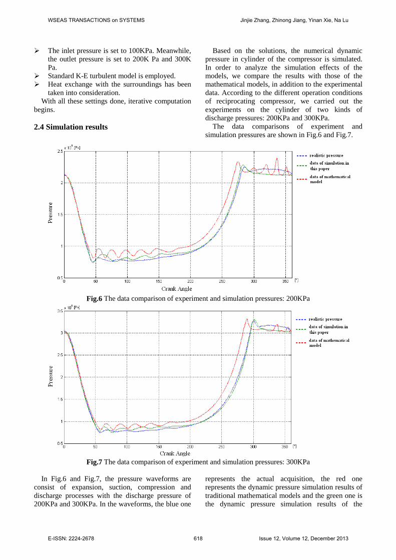
The data comparisons of experiment and simulation pressures are shown in Fig.6 and Fig.7.
Fig.6 The data comparison of experiment and simulation pressures: 200KPa
Fig.7 The data comparison of experiment and simulation pressures: 300KPa
In Fig.6 and Fig.7, the pressure waveforms are consist of expansion, suction, compression and discharge processes with the discharge pressure of 200KPa and 300KPa. In the waveforms, the blue one
represents the actual acquisition, the red one represents the dynamic pressure simulation results of traditional mathematical models and the green one is the dynamic pressure simulation results of the
WSEAS TRANSACTIONS on SYSTEMS Jinjie Zhang, Zhinong Jiang, Yinan Xie, Na Lu
E-ISSN: 2224-2678 618 Issue 12, Volume 12, December 2013

method in this paper. It can get conclusions that the simulation results of traditional mathematical models have significant differences in suction, compression and exhaust stage with the actual data. However the simulation results of FLUENT software agree with
the actual data very well because it has applied the entity modeling method to simulate the structure of reciprocating compressor.
The error analysis is shown in Table 2.
Table 2 Error analysis of simulation results
Different discharge pressure 200KPa 300KPa
Mathematical model
Simulation of this paper
Mathematical model
Simulation of this paper
Total error 10.47% 3.07% 11.78% 3.64% Error of expansion process 3.5% 1.04% 2.75% 2.21% Error of suction process 14.4% 4.91% 14.35% 6.14% Error of compress process 15.6% 1.85% 17.96% 2.26% Error of discharge process 2.73% 2.81% 4.70% 2.52%
According to the results, it can get conclusions as
follows: The FLUENT software can take simulation of
the dynamic pressure effectively and the errors will be acceptable in engineering.
The simulation accuracy of the model with FLUENT software is better than that of the mathematical models.
The method in this paper can be applied to simulate the real dynamic pressure in cylinders in order to analyze the working conditions of the parts in reciprocating motion.
3 Dynamic analysis of connecting rod
The crankpin bearing is the key node transmitting torque from crankshaft in the motion. Because of the coercive lubrication of reciprocating compressors, abrasion of crankpin bearing in stable operating condition seldom happens. However, due to the operating condition changes frequently in the production, the dynamic pressure in cylinder is unstable. This affects the dynamics behaviors of crankshaft and connecting rod. Therefore, in such conditions, Babbitt Metal on the crankpin bearing under dynamic loads will be easily worn with fatigue. The lubricant film will be damaged, the fatigue surface will expand rapidly, the vibration and noise will occur. So vibration monitoring is an effective method to capture the feature of crankpin bearing fault.
However, the vibration signals of reciprocating compressor has significant angular characteristics in
phase domain and almost reciprocating compressors in plants cannot monitor the dynamic pressure, it is unable to do the dynamics analysis for the moving parts of the compressor. How to confirm the abnormal phases is the critical task in fault diagnosis.
This paper establishes theoretical models of the key parts of reciprocating compressor to take mechanical analysis based on dynamic pressure simulation. The dynamic analysis of crankpin bearing makes the fault feature extraction possible, which laid the foundation for the realization of the early alarming and diagnosis of the faults. 3.1 The dynamics models 3.1.1 The mechanical models of reciprocating motion
The piston components, piston rod and crosshead components make reciprocating movements whose mass are pisM , rodM and croM , as shown in Fig.8. However, the connecting rod is the component which makes composite motions of reciprocating and rotary. The connecting rod is comprised with the rod body, the bolts, the crankpin bearing and connecting rod pin bushing. The whole mass of connecting rod is
conM . Normally, The conM will be separated in two parts: reconM − and roconM − , which represent the mass concentrate in connecting rod pin with reciprocating motion and the mass concentrate in the crankpin bearing with rotary motion, as shown in Fig.9.
conroconrecon MMM =+ −− , (4)
021 =− −− LMLM roconrecon . (5)
WSEAS TRANSACTIONS on SYSTEMS Jinjie Zhang, Zhinong Jiang, Yinan Xie, Na Lu
E-ISSN: 2224-2678 619 Issue 12, Volume 12, December 2013

X
YFcb-cf
Fcb-con
Pin
PoutMpis
Mrod
McroMcon
α θFpinFpin-y
Fpin-x
Fcb
Fig.8 The key components of reciprocating compressor
Mcon
Mcon-re Mcon-ro
L1 L2
L
Fig.9 The mass separation of connecting rod
Defining the rotary speed as ω , pressure in
outside cylinder as outcyp − , the press area at the
outside of the piston as outpisS − , pressure in inside
cylinder as incyp − , the press area at the inside of the
piston as inpisS − . We established the coordinate
system whose origin is the center of the crankshaft. The X-axis is taken to be horizontal and the Y-axis is taken to be vertical. The positive direction of the X-axis is from piston to crank shaft, as shown in Fig. 8.
As concentrating part of mass of the connecting rod which take reciprocating motion to the crosshead pin, we can define the force on the crosshead pin exerted by connecting rod as pinF
, as shown in
Fig.8. The pinF
can be divided into two parts:
xpinF −
and ypinF −
. xpinF −
and ypinF −
are along the X-axis and Y-axis respectively. The forces of all the components which take reciprocating motion can be expressed as follows:
rodpisxpininpisincyoutpisoutcy MMFfSpSp +=+++ −−−−− ()(
aMM reconcro)−++ (6)
In reciprocating motion, the friction force will be ignored usually. Improving the Eq. (6) as:
outpisoutcyreconcrorodpisxpin SpaMMMMF −−−− −+++=
()(
)inpisincy Sp −−+ (7)
On the direction of X-axis, the acceleration of all the components which take the reciprocating motion can be defined as:
)cos2cos(*2 θθλω += Ra . (8) In the Eq. (8), λ is defined as the ratio of the
crank radius and connecting rod length, α is defined as the angle between the connecting rod and the positive direction of the X-axis, θ is defined as the angle between the crank and the negative direction of the X-axis. The relationship amongλ , α andθ can be defined as:
)sinarcsin( θλα = , (9)
whereθαλ
sinsin
==LR .
From Fig. 8, we can get the equation:
αcos/xpinpin FF −=
. (10)
According to the law of action and reaction, on the crankpin bearing, the force from crankpin to the bearing can be defined as concbF −
which is along the
centre line of connecting rod. concbF −
can be calculated as follows:
−+++== −− aMMMMFF reconcrorodpispinconcb
)[(
αcos/)]( inpisincyoutpisoutcy SpSp −−−− + (11)
3.1.2 The mechanical models of rotary motion In addition to reciprocating motion, the connecting
rod also rotates around the center of the crankshaft. The mass of connecting rod which takes rotate motion can be concentrated at the center of crankpin bearing simply as shown in Fig.9. The mass can be defined as roconm − . Centrifugal inertia force of the mass is along the crank radius outward.
Therefore, the force from crankpin to the crankpin bearing can be defined as cfcbF −
whose direction
WSEAS TRANSACTIONS on SYSTEMS Jinjie Zhang, Zhinong Jiang, Yinan Xie, Na Lu
E-ISSN: 2224-2678 620 Issue 12, Volume 12, December 2013

is along the crank radius inward. The calculation equation for cfcbF −
is:
2ωRMF roconcfcb −− = . (12)
According to the mechanics analysis of the reciprocating and rotary motions, the composition of
forces on the crankpin bearing can be defined as cbF
which can be calculated by:
cfcbconcbcb FFF −− += . (13)
3.2 Dynamics analysis results
The abrasion of crankpin bearing is difficult to be simulated in experiments and easily leads to the
abrasion on the surface of crankpin, so we take a reciprocating compressor in plant as object to make dynamic analysis of connecting rod under the real working condition.
The compressor is a horizontal reciprocating compressor with two-stage at a plant of Petrochina. The abrasion fault of crankpin bearing in this compressor occurred on July 8 in 2013 with dropping of lubricating oil pressure in the second stage cylinder and increasing of vibration on crank case. Then the compressor stopped automatically due to effect of the vibration protection system. The compressor information is shown in Table 3. As shown in Fig.10, the on-line monitoring system has been installed on the compressor.
Table 3 Information of the compressor
The parameters Value The parameters Value Unit number K202B Drive mode motor Cylinder quantity 2 Compress medium hydrogen Suction pressure of second stage 0.853MPa Discharge pressure of second stage 2.426MPa The piston diameter of second stage 643.9mm The piston rod diameter of second stage 130mm
The piston mass of second stage 290Kg The piston rod mass of second stage 247.7Kg The crosshead mass of second stage 585Kg The connecting rod mass of second
stage 538Kg
The radius of crank shaft 180 mm The ratio of crank radius and connecting rod length 0.2
Explosion-proof
box
Explosion-proof
boxCrankcase
Motor
Compressor platform range
Piston roddispleasement
Crankcase vibrationKey phase
Instrument lines
Main Signal cables
Main Signal cables
Cabinet
Valve temperature
Fig.10 Schematic diagram showing transducers positions and the compressor’s structure
According to the structure parameters in Table 3, we simulated the theoretical dynamic pressure of the second-stage cylinder under the history operation
condition, as shown in Fig.11. Based on the above dynamics models, we made mechanics analysis for the compressor and acquired the feature of force
WSEAS TRANSACTIONS on SYSTEMS Jinjie Zhang, Zhinong Jiang, Yinan Xie, Na Lu
E-ISSN: 2224-2678 621 Issue 12, Volume 12, December 2013

trend on crankpin bearing in the crank coordinate system. So the abrasion phase can be located
precisely. Specific results are shown in Fig.12.
Fig.11 The dynamics pressure of the second stage
Fig.12 The trend of force on the crankpin bearing in crank coordinate system
Usually the angle used in reciprocating compressor fault diagnosis refers to the relative rotary angle of crank [13, 19, 27]. It is the start point when the piston locates at outer dead point of cylinder. After time t, multiplying the speed by time, we get the rotary angle: tωθ = . But the actual specific abrasion position cannot be determined in the crank coordinate system. It has to convert the
angle into the crankpin bearing coordinate system. So in this paper, we established the coordinate system in which the X'-axis is taken to be the center line of the connecting rod and the Y'-axis is taken to be the vertical of the center line. This coordinate system not only rotates but also swings around the center of crankshaft, as shown in Fig.13.
X
Y
X’Y’
Fcb-x
Fcb-yFcb
α
Pin
PoutMpis
MrodMcro
Mcon
β
δ
Fig.13 Different coordinate systems of the reciprocating compressor Assuming that when the crank angle is tωθ = ,
the force on the crankpin bearing is cbF . The angle between the force direction and the X-axis is β and the angle between the center line of the connecting rod and the X-axis isα . At this time, in the crankpin bearing coordinate system, the angle between force direction and the X'-axis is αβ − .
Taking the structure parameters and the results of dynamic pressure simulation into the dynamics models of the reciprocating compressor and solving the models, we applied the polar diagrams to express the tendency of the force on the crankpin bearing, as shown in Fig.14 and Fig.15. Fig.14 was drawn referring to the crank coordinate system and Fig.15 was drawn referring the crankpin bearing coordinate system.
Fig.15 The force waveform on crankpin bearing in the crankpin bearing coordinate system
WSEAS TRANSACTIONS on SYSTEMS Jinjie Zhang, Zhinong Jiang, Yinan Xie, Na Lu
E-ISSN: 2224-2678 622 Issue 12, Volume 12, December 2013

Fig.14 The force waveform on crankpin bearing in the crank coordinate system
It can get conclusions from above results as: (1) The force acting on the crankpin bearing of the
second stage presents alternations. At the first half cycle, in the crank coordinate system the biggest peak value of the force occur at the angle of 120°, and at the second half cycle the angle is 290°. Therefore the abrasion of the crankpin bearing will
occur at the two angles of 120°and 290°easily. (2) In the crankpin bearing coordinate system, the
abrasion area occur at the angles of 330°and 210°near the junction of the two crankpin bearings.
The conclusions play an important role in fault diagnosis. They can be used to extract the feature of vibration signals and be used for positioning the abrasion of crankpin bearing precisely. 4 The application results
As shown in Fig.10, the compressor has been installed the on-line monitoring system which comprised with following transducers: accelerometer, proximity probe, temperature transducer and key-phase transducer. These transducers will record the faults data in different periods. There are two acceleration transducers installed on the crank case. V2 measure point is near the second stage cylinder which has the fault. In Fig.16, it has shown the vibration tendency of the crank case in different periods. We can see the historical waveforms that the vibration waveforms of crankcase become worse and worse as the fault deteriorating.
(a) The vibration waveform in normal period
(b) The vibration waveform at the beginning of the fault
(c) The vibration waveform when the fault deteriorated Fig.16 The crankcase vibration waveforms of the fault in different periods
WSEAS TRANSACTIONS on SYSTEMS Jinjie Zhang, Zhinong Jiang, Yinan Xie, Na Lu
E-ISSN: 2224-2678 623 Issue 12, Volume 12, December 2013
Choosing a waveform in normal period as object to be compared with waveforms of different periods, we calculate the variances of different waveforms phases. The single cycle waveform has been divided into 36 sections and we get the feature of different phases of different historical waveforms, as shown in Fig.17.
Fig.17 The variances of different waveforms in different phases
As shown in Fig.17, in crank coordinate system,
the vibration waveform has abnormal at 110°compared with normal waveform at the beginning of the fault. When the fault deteriorated, the abnormities occur from 40° to 150°and it is the worst at the angle of 110° . However there are no dramatic changes at the angles behind 180°of the vibration waveform.
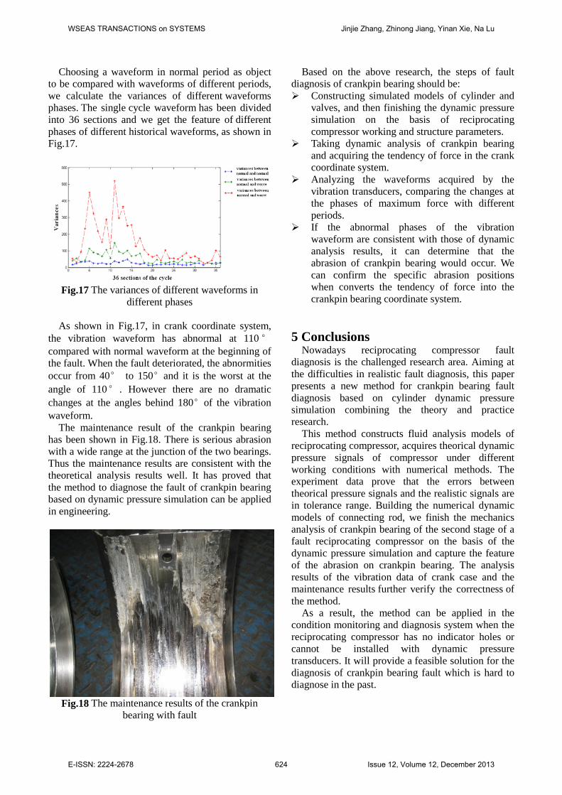
The maintenance result of the crankpin bearing has been shown in Fig.18. There is serious abrasion with a wide range at the junction of the two bearings. Thus the maintenance results are consistent with the theoretical analysis results well. It has proved that the method to diagnose the fault of crankpin bearing based on dynamic pressure simulation can be applied in engineering.
Fig.18 The maintenance results of the crankpin bearing with fault
Based on the above research, the steps of fault diagnosis of crankpin bearing should be: Constructing simulated models of cylinder and
valves, and then finishing the dynamic pressure simulation on the basis of reciprocating compressor working and structure parameters.
Taking dynamic analysis of crankpin bearing and acquiring the tendency of force in the crank coordinate system.
Analyzing the waveforms acquired by the vibration transducers, comparing the changes at the phases of maximum force with different periods.
If the abnormal phases of the vibration waveform are consistent with those of dynamic analysis results, it can determine that the abrasion of crankpin bearing would occur. We can confirm the specific abrasion positions when converts the tendency of force into the crankpin bearing coordinate system.
5 Conclusions
Nowadays reciprocating compressor fault diagnosis is the challenged research area. Aiming at the difficulties in realistic fault diagnosis, this paper presents a new method for crankpin bearing fault diagnosis based on cylinder dynamic pressure simulation combining the theory and practice research.
This method constructs fluid analysis models of reciprocating compressor, acquires theorical dynamic pressure signals of compressor under different working conditions with numerical methods. The experiment data prove that the errors between theorical pressure signals and the realistic signals are in tolerance range. Building the numerical dynamic models of connecting rod, we finish the mechanics analysis of crankpin bearing of the second stage of a fault reciprocating compressor on the basis of the dynamic pressure simulation and capture the feature of the abrasion on crankpin bearing. The analysis results of the vibration data of crank case and the maintenance results further verify the correctness of the method.
As a result, the method can be applied in the condition monitoring and diagnosis system when the reciprocating compressor has no indicator holes or cannot be installed with dynamic pressure transducers. It will provide a feasible solution for the diagnosis of crankpin bearing fault which is hard to diagnose in the past.
WSEAS TRANSACTIONS on SYSTEMS Jinjie Zhang, Zhinong Jiang, Yinan Xie, Na Lu
E-ISSN: 2224-2678 624 Issue 12, Volume 12, December 2013

Acknowledge This work was supported by the National Basic
Research Program of China (973 Program) under Grant No. 2012CB026000 and the National Natural Science Foundation of China under Grant No. 51135001. We also would like to thank various domain experts from PetroChina. References [1] H. Cui, L. Zhang, R. Kang, X. Lan, Research on fault diagnosis for reciprocating compressor valve using information entropy and SVM method, Journal of Loss Prevention in the Process Industries, 22 (2009) 864-867. [2] M. JIN, J. ZHINONG, A New Feature Reduction Method and Its Application in the Reciprocating Engine Fault Diagnosis, WSEAS transactions on signal processing, 8 (2012) 54-63. [3] V. Ghate, S. Dudul, Induction machine fault detection using support vector machine based classifier, WSEAS Transactions on Systems, 8 (2009) 591-603. [4] Zhinong Jiang, Jinjie Zhang, J. Ao, Research On Reciprocating Compressor Indicator Diagram Fault Recognition Based On Support Vector Machine, Fluid Machinery, 40 (2012) 21-25. [5] B.-S. Yang, W.-W. Hwang, D.-J. Kim, A. Chit Tan, Condition classification of small reciprocating compressor for refrigerators using artificial neural networks and support vector machines, Mechanical Systems and Signal Processing, 19 (2005) 371-390. [6] K. Feng, Z. Jiang, W. He, B. Ma, A recognition and novelty detection approach based on Curvelet transform, nonlinear PCA and SVM with application to indicator diagram diagnosis, Expert Systems with Applications, 38 (2011) 12721-12729. [7] F. Wang, L. Song, L. Zhang, H. Li, Fault Diagnosis for Reciprocating Air Compressor Valve Using PV Indicator Diagram and SVM, in: Information Science and Engineering (ISISE), 2010 International Symposium on, IEEE, 2010, pp. 255-258. [8] J. Cho, S. Moon, A numerical analysis of the interaction between the piston oil film and the component deformation in a reciprocating compressor, Tribology International, 38 (2005) 459-468. [9] C. Baldizzone, A. Gruttadauria, C. Mapelli, D. Mombelli, Investigation of Failure in a Crankpin of a Motorcycle Engine, Journal of failure analysis and prevention, 12 (2012) 123-129. [10] X.-l. Xu, Z.-w. Yu, Failure Investigation of a Diesel Engine Piston Pin, Journal of Failure Analysis and Prevention, 10 (2010) 245-248.
[11] B. Krishna, A. Verma, J.F. Welch, Failure analysis of cylinder clamping rods in diesel engines, Practical Failure Analysis, 1 (2001) 51-55. [12] A. Broatch, X. Margot, A. Gil, Computational study of the sensitivity to ignition characteristics of the resonance in DI diesel engine combustion chambers, Engineering Computations, 24 (2007) 77-96. [13] M. Elhaj, F. Gu, A. Ball, A. Albarbar, M. Al-Qattan, A. Naid, Numerical simulation and experimental study of a two-stage reciprocating compressor for condition monitoring, Mechanical Systems and Signal Processing, 22 (2008) 374-389. [14] J. Cho, D. Yang, Three-dimensional finite element simulation of connecting rod forging using a new remeshing scheme, Engineering Computations, 15 (1998) 777-803. [15] I.A. Sultan, A. Kalim, Improving reciprocating compressor performance using a hybrid two-level optimisation approach, Engineering Computations, 28 (2011) 616-636. [16] X.L. Xu, Z.W. Yu, Failure analysis of a diesel engine connecting rod, Journal of Failure Analysis and Prevention, 7 (2007) 316-320. [17] A. Francisco, A. Fatu, D. Bonneau, Using design of experiments to analyze the connecting rod big-end bearing behavior, Journal of tribology, 131 (2009). [18] P.K. Goenka, K.P. Oh, An optimum connecting rod design study―a lubrication viewpoint, Journal of tribology, 108 (1986) 487-496. [19] G.B. Daniel, K.L. Cavalca, Analysis of the dynamics of a slider–crank mechanism with hydrodynamic lubrication in the connecting rod–slider joint clearance, Mechanism and Machine Theory, 46 (2011) 1434-1452. [20] F. Neri, Learning and predicting financial time series by combining natural computation and agent simulation, in: Applications of Evolutionary Computation, Springer, 2011, pp. 111-119. [21] F. Zetian, X. Feng, Z. Yun, Z. XiaoShuan, Pig-vet: a web-based expert system for pig disease diagnosis, Expert Systems with Applications, 29 (2005) 93-103. [22] J.F.S. Gomes, F.R. Leta, Applications of computer vision techniques in the agriculture and food industry: a review, European Food Research and Technology, 235 (2012) 989-1000. [23] W. Zhong-Qing, J. Zhi-Nong, M. Bo, Z. Xin, The slow-changing alarm system of condition monitoring for rotating machinery, Wseas Transactions on Systems, 9 (2010) 52-61. [24] Z. JIANG, J. ZHANG, M. JIN, B. MA, An expert system based on multi-source signal integration for reciprocating compressor, WSEAS
WSEAS TRANSACTIONS on SYSTEMS Jinjie Zhang, Zhinong Jiang, Yinan Xie, Na Lu
E-ISSN: 2224-2678 625 Issue 12, Volume 12, December 2013

TRANSACTIONS on SYSTEMS, 12 (2013) 266-279. [25] P. Cyklis, CFD simulation of the flow through reciprocating compressor self-acting valves, in: International Compressor Engineering Conference, Purdue University, USA, 1994, pp. 427-432. [26] Y.V. Birari, S.S. Gosavi, P.P. Jorwekar, Use of CFD in design and development of R404a reciprocating compressor, in: International Compressor Engineering Conference, Purdue University, USA, 2006, pp. 1-7. [27] J. Becerra, F. Jimenez, M. Torres, D. Sanchez, E. Carvajal, Failure analysis of reciprocating compressor crankshafts, Engineering Failure Analysis, 18 (2011) 735-746.
WSEAS TRANSACTIONS on SYSTEMS Jinjie Zhang, Zhinong Jiang, Yinan Xie, Na Lu
E-ISSN: 2224-2678 626 Issue 12, Volume 12, December 2013


