A Network Architecture for Heterogeneous Mobile...
80
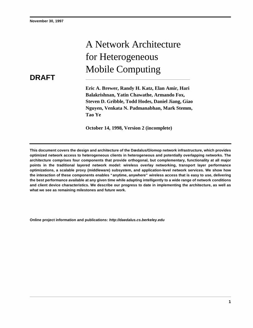
November 30, 1997 1 DRAFT A Network Architecture for Heterogeneous Mobile Computing Eric A. Brewer, Randy H. Katz, Elan Amir, Hari Balakrishnan, Yatin Chawathe, Armando Fox, Steven D. Gribble, Todd Hodes, Daniel Jiang, Giao Nguyen, Venkata N. Padmanabhan, Mark Stemm, Tao Ye October 14, 1998, Version 2 (incomplete) This document covers the design and architecture of the Dædalus/Glomop network infrastructure, which provides optimized network access to heterogeneous clients in heterogeneous and potentially overlapping networks. The architecture comprises four components that provide orthogonal, but complementary, functionality at all major points in the traditional layered network model: wireless overlay networking, transport layer performance optimizations, a scalable proxy (middleware) subsystem, and application-level network services. We show how the interaction of these components enables “anytime, anywhere” wireless access that is easy to use, delivering the best performance available at any given time while adapting intelligently to a wide range of network conditions and client device characteristics. We describe our progress to date in implementing the architecture, as well as what we see as remaining milestones and future work. Online project information and publications: http://daedalus.cs.berkeley.edu
Transcript of A Network Architecture for Heterogeneous Mobile...
November 30, 1997
1
DRAFT
A Network Architecture for Heterogeneous Mobile Computing
Eric A. Brewer, Randy H. Katz, Elan Amir, Hari Balakrishnan, Yatin Chawathe, Armando Fox, Steven D. Gribble, Todd Hodes, Daniel Jiang, Giao Nguyen, Venkata N. Padmanabhan, Mark Stemm, Tao Ye
October 14, 1998, Version 2 (incomplete)
This document covers the design and architecture of the Dædalus/Glomop network infrastructure, which providesoptimized network access to heterogeneous clients in heterogeneous and potentially overlapping networks. Thearchitecture comprises four components that provide orthogonal, but complementary, functionality at all majorpoints in the traditional layered network model: wireless overlay networking, transport layer performanceoptimizations, a scalable proxy (middleware) subsystem, and application-level network services. We show howthe interaction of these components enables “anytime, anywhere” wireless access that is easy to use, deliveringthe best performance available at any given time while adapting intelligently to a wide range of network conditionsand client device characteristics. We describe our progress to date in implementing the architecture, as well aswhat we see as remaining milestones and future work.
Online project information and publications: http://daedalus.cs.berkeley.edu

DRAFT
2 A Network Architecture for Heterogeneous Mobile Computing
DRAFT
3
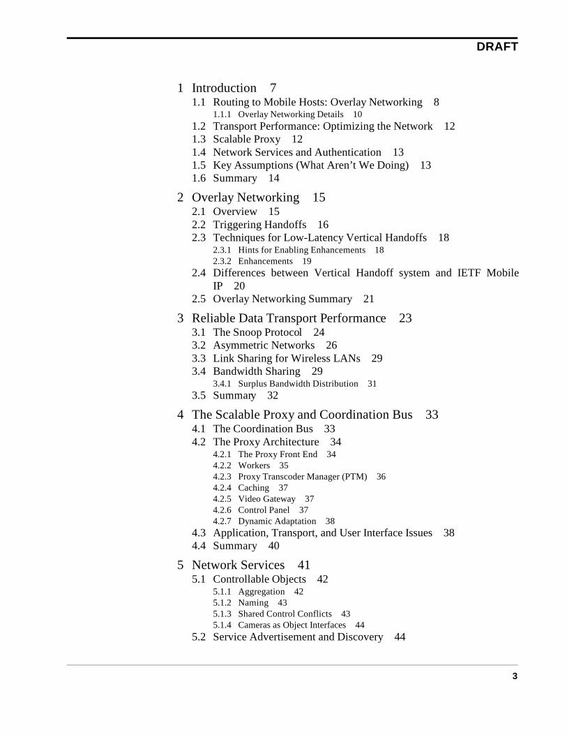
1 Introduction 71.1 Routing to Mobile Hosts: Overlay Networking 8
1.1.1 Overlay Networking Details 101.2 Transport Performance: Optimizing the Network 121.3 Scalable Proxy 121.4 Network Services and Authentication 131.5 Key Assumptions (What Aren’t We Doing) 131.6 Summary 14
2 Overlay Networking 152.1 Overview 152.2 Triggering Handoffs 162.3 Techniques for Low-Latency Vertical Handoffs 18
2.3.1 Hints for Enabling Enhancements 182.3.2 Enhancements 19
2.4 Differences between Vertical Handoff system and IETF MobileIP 20
2.5 Overlay Networking Summary 21
3 Reliable Data Transport Performance 233.1 The Snoop Protocol 243.2 Asymmetric Networks 263.3 Link Sharing for Wireless LANs 293.4 Bandwidth Sharing 29
3.4.1 Surplus Bandwidth Distribution 313.5 Summary 32
4 The Scalable Proxy and Coordination Bus 334.1 The Coordination Bus 334.2 The Proxy Architecture 34
4.2.1 The Proxy Front End 344.2.2 Workers 354.2.3 Proxy Transcoder Manager (PTM) 364.2.4 Caching 374.2.5 Video Gateway 374.2.6 Control Panel 374.2.7 Dynamic Adaptation 38
4.3 Application, Transport, and User Interface Issues 384.4 Summary 40
5 Network Services 415.1 Controllable Objects 42
5.1.1 Aggregation 425.1.2 Naming 435.1.3 Shared Control Conflicts 435.1.4 Cameras as Object Interfaces 44
5.2 Service Advertisement and Discovery 44
DRAFT
4
5.3 Mapping Client Controls to Exported Objects 455.3.1 Transduction Protocols 455.3.2 Complex Behaviors 45
5.4 Implementing Service Interaction 465.4.1 Basic Operation 465.4.2 System Setup 465.4.3 Message-level Detail 485.4.4 Client Bootstrap 485.4.5 Beaconing 495.4.6 Charon: Proxied Secure Access 505.4.7 Scoped Access Control 515.4.8 Client Interfaces 525.4.9 Naming Scheme 53
5.5 Prototype Mobile Services 545.5.1 Maps 545.5.2 Proxy and Gateway Autoconfiguration 555.5.3 Location Tracking 565.5.4 Printer Access 565.5.5 Motorized Cameras 565.5.6 405 Soda Room Interaction 575.5.7 326 Soda Room Interaction 59
5.6 Discussion 595.7 Related Work 605.8 Continuing Work and Future Directions 61
5.8.1 Wide-area issues 615.8.2 Building control and support 615.8.3 Delegating operations 625.8.4 Queued RPC 625.8.5 Maps 625.8.6 Interface specification grammar and compiler 625.8.7 Fault tolerance 625.8.8 Geographic locality 625.8.9 Multimedia collaboration control architecture 635.8.10 Conference control primitives for lightweight sessions 63
5.9 Conclusions 64
6 The Network Stacks 656.1 The Basestation Network Stack 65
6.1.1 Black-Box Basestations 656.1.2 Dædalus-Aware Basestations 65
6.2 The Client Network Stack 676.3 The Proxy Network Stack (for Clients) 686.4 Network Stack Summary 68
7 Summary 717.1 The Principles Revisited 717.2 Summary 73
8 Glossary 75

DRAFT
5
9 References 79

DRAFT
6
Introduction DRAFT
7
1 Introduction
“People and their machines should be able to access information and communicatewith each other easily and securely, in any medium or combination of media —voice, data, image, video, or multimedia — any time, anywhere, in a timely, cost-effective way.”
Dr. George H. HeilmeierIEEE Communication
October 1992
More than any other, this statement captures the broad goals of our project and the resultingarchitecture that is the subject of this document. The highlighted words carry tremendous conse-quences that form the driving principles of this work — in fact, we will derive the principles fromthese words, and the architecture from these principles.
Access Our mantra is “Access is the Killer App”, by which we mean that the key tomobile computing and portable devices — PDA’s, smart phones, and laptops— is not an application per se, but rather access to both my desktop environ-ment (at home or office) and to the internet at large.
Anytime, Anywhere The infrastructure required for this access must be permanently deployedand readily available from everywhere. Everywhere includes indoors, out-doors, in cities and in remote regions.
Principle 1: Heterogeneous Networks: The infrastructure must include wire-less networks that have a mixture of global and indoor coverage,thus requiring a heterogeneous collection of networks.
To optimize network performance, we must use support a variety of net-works and pick the best among them for the current location. We call thisOverlay Networking, since a set of networks are overlaid onto the samephysical area.
Principle 2: Scalable: The infrastructure must scale to support millions ofusers.
Principle 3: Highly Available: The infrastructure must be available all of thetime.
Easily It is not enough to have access; that access must be simple to use.
Principle 4: Transparent Access: The detection and setup of a network con-nection should be automatic. Users shouldn’t have to know whatnetworks are in range.
Principle 5: Localized Service: The detection and setup of local network ser-vices should be automatic. Users shouldn’t have to know whatservices are available at their current location.

Introduction DRAFT
8
Securely Access to your own stuff requires authentication. Access to local resourcesmay also require authentication, since not all visitors are treated the same.
Principle 6: Global Authentication: We must authenticate users using a glo-bally available security infrastructure, such as public-key cryp-tography or Kerberos.
Any Medium We must deal with a wide variety of data.
Principle 7: Multimedia: The infrastructure must support graphics, audioand video in addition to text.
Timely The performance should be the best possible (for the current location).
Principle 8: Performance: The user’s data should arrive as fast as possible.This includes selecting the best network, optimizing the networkperformance, and optimizing the content at the application level.
Cost Effective The infrastructure should be designed to minimize the costs and share andamortize resources as much as possible.
Principle 9: Heterogeneous Clients: Complexity should be pushed into theinfrastructure, where it can be amortized over all of the activeusers. The infrastructure should support both inexpensive clientdevices, such as smart phones, and more sophisticated comput-ers, such as high-end laptops.
Even with some network-level optimizations, there will be times the networkperformance is poor and we need application-level support. In particular, wewould like to optimize the data sent to reduce the demands on the client andnetwork without reducing the information content.
Principle 10: Dynamic Adaptation: The data sent to the user should be opti-mized for timeliness, carrying the most information in the leastamount of time. The nature of this adaptation depends on the cur-rent network, the preferences of the user, and the nature of thedata (text is much different than graphics).
These ten principles are driving forces behind the architecture. In the next four sections, welook at the key elements of the architecture and see how they meet these principles. These elementsare largely orthogonal; they can be used independently of one another, but they do work welltogether.
1.1 Routing to Mobile Hosts: Overlay Networking
Because we must deal with several overlapping networks to achieve the best performance, weneed a way to transparently switch networks. Furthermore, the best available network changes dueto mobility and congestion. Thus the first task of the architecture is simply to route packets to amobile host using the best available network. The overlay networking subsystem deals with thedetection of available networks, the selection of the best network, and the transparent switch toeither a another cell in the same network, or to a completely new network.

Introduction DRAFT
9
Figure 1 shows a series of overlapping networks. The mobile host can be in any of the ovals,and when in an oval it is typically also in an oval for each of the networks above it. For example, amobile host in a cell of an in-building network is typically also in a cell for each of the campus-area, metropolitan-area and regional networks. The mobile host can move among these cells eitherhorizontally (within a network) or vertically (between networks); a cell transition is called a hand-off, and overlay networking thus supports both vertical and horizontal handoffs.
Thus, the two key goals of overlay networking are to detect and monitor the currently availablenetworks and to manage handoffs. Thus overlay networking supports the principles of Heteroge-neous Networks and Transparent Access. The former comes by definition, since it assume multi-ple overlapping heterogeneous networks, and the latter comes from the detection of availablenetworks.
Overlay networking also helps with several other principles:
• Highly Available: by exploiting multiple networks, we achieve redundancy andthus improve availability of connectivity.
• Localized Services: the use of multiple networks, especially those with smallcells, such as IR, helps the infrastructure with the location of the client. This in turnenables accurate localized services. Note that just knowing which networks areavailable provides location information.
• Performance: overlay network improves performance by selecting the best avail-able network.
• Dynamic Adaptation: by knowing the current network used by a client, overlaynetworking helps with the parameters for dynamic adaptation, i.e., we can more
FIGURE 1. An overlay network withfour overlapping heterogeneousnetworks.

Introduction DRAFT
10
accurately tune the content for a user because we know the properties of their net-work connection.
Given this high-level description of overlay networking, we now look a level deeper andexplore the mechanisms of used.
1.1.1 Overlay Networking Details
Figure 2 shows the basic architecture. The mobile host is on the left and the server is at the topright. There are three overlaid networks shown, each as a horizontal plane; horizontal handoffoccurs between basestations on the same plane (network), while vertical handoff occurs betweenthe planes.
There are two kinds of basestations in practice: black-box basestations, those over which wehave no control, and Dædalus-aware basestations, we can influence enough to run our protocols.This distinction is important since we want to exploit existing deployed networks over which wehave essentially no control. Typically, black-box basestations have proprietary protocols for net-work detection and horizontal handoff. We can normally exploit the network detection stuff for ourpurposes, but control of handoffs is usually out of our control. Thus, black-box basestations typi-cally have the following responsibilities:
• Provide routing to client
• Manage local wireless network
With Dædalus-aware basestations, we have sufficient control such that we can control handoffsfairly precisely; they have the following responsibilities:
• Provide beacon to client
• Optimize network against wireless losses
G WG W
IPInternet
GW
GW
GW
Server
Proxy Host
Home AgentWireless Subnets
G W
Basestations ForeignAgent
LocalProxy Host
LocalServices
HorizontalHandoff
VerticalHandoff
Overlay IP
FIGURE 2. The basic system architecture has four components above the network level. In addition to clients and servers,basestations provide wireless connectivity, the home agent manages mobility and tracks the client, and proxies providescontent optimization and security.
Introduction DRAFT
11
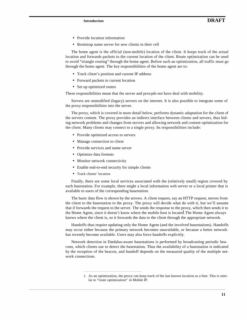
• Provide location information
• Bootstrap name server for new clients in their cell
The home agent is the official (non-mobile) location of the client. It keeps track of the actuallocation and forwards packets to the current location of the client. Route optimization can be usedto avoid “triangle routing” through the home agent. Before such an optimization, all traffic must gothrough the home agent. The key responsibilities of the home agent are to:
• Track client’s position and current IP address
• Forward packets to current location
• Set up optimized routes
These responsibilities mean that the server and proxy do not have deal with mobility.
Servers are unmodified (legacy) servers on the internet. It is also possible to integrate some ofthe proxy responsibilities into the server.
The proxy, which is covered in more detail below, performs dynamic adaptation for the client ofthe servers content. The proxy provides an indirect interface between clients and servers, thus hid-ing network problems and changes from servers and allowing network and content optimization forthe client. Many clients may connect to a single proxy. Its responsibilities include:
• Provide optimized access to servers
• Manage connection to client
• Provide services and name server
• Optimize data formats
• Monitor network connectivity
• Enable end-to-end security for simple clients
• Track clients’ location
Finally, there are some local services associated with the (relatively small) region covered byeach basestation. For example, there might a local information web server or a local printer that isavailable to users of the corresponding basestation.
The basic data flow is shown by the arrows. A client request, say an HTTP request, moves fromthe client to the basestation to the proxy. The proxy will decide what do with it, but we’ll assumethat if forwards the request to the server. The sends the response to the proxy, which then sends it tothe Home Agent, since it doesn’t know where the mobile host is located.1 The Home Agent alwaysknows where the client is, so it forwards the data to the client through the appropriate network.
Handoffs thus require updating only the Home Agent (and the involved basestations). Handoffsmay occur either because the primary network becomes unavailable, or because a better networkhas recently become available. Users may also force handoffs explicitly.
Network detection in Dædalus-aware basestations is performed by broadcasting periodic bea-cons, which clients use to detect the basestation. Thus the availability of a basestation is indicatedby the reception of the beacon, and handoff depends on the measured quality of the multiple net-work connections.
1. As an optimization, the proxy can keep track of the last known location as a hint. This is simi-lar to “route optimization” in Mobile IP.

Introduction DRAFT
12
At a high level, this a fairly complete picture of the architecture. The three major missing piecesare the optimizations of the transport layer, the proxy, and available services. The next three sub-sections cover these pieces.
1.2 Transport Performance: Optimizing the Network
There are many challenges presented by a heterogeneous collection of networks that togetherprovide wide-area wireless access anytime, anywhere. The primary problems are low bandwidth,high error rates, asymmetric performance, and high latency. We have extended TCP to mitigate allof these issues. We also multiplex many short connections to the same place over one long-livedconnection, called a “session”, which improves the performance of the connections.
Thus, the Transport Performance subsystem primarily supports the principle of Performance.It also supports several other principles:
• Highly Available: The improved error handling increases the availability of thenetwork.
• Multimedia: By allowing the application to indicated its requirements throughdelivery classes, the architecture allows better performance for multimedia data.For example, we can avoid retransmitting lost audio or video packets, since theywould likely arrive too late to be useful and the rendering of the data will probablybe OK without these packets.
• Dynamic Adaptation: Because we can monitor the connection between the clientand the proxy, we can tune the content based on the actual bandwidth, thus maxi-mizing the effectiveness of the transfer.
Although transport performance is largely an optimization in this architecture, the wide varietyof networks and network problems that we encounter indicates that these issues are not merely anoptimization, but required parts of practically useful system.
1.3 Scalable Proxy
A major component of the architecture is the scalable proxy, which provides dynamic adapta-tion of data sent to the user based on the user’s device, network connectivity and preferences. Itthus provides timely data despite the limitations of the network, and acts as intermediary betweenclient and server, thus hiding any disconnections or client limitations.
The proxy manages all of the data seen by the client and uses caching to improve performance.Thus, clients ask the proxy for a particular object and the proxy will get it either from the cache orfrom the internet. The proxy also handles authentication in order to provide access to restrictedresources (such as a user’s own e-mail).
The proxy is the key method by which we meet the goals of Heterogeneous Clients andDynamic Adaptation. In particular, since heterogeneous clients can’t all handle standard servers(e.g. HTML), the proxy transforms the data into formats that the client can handle. The proxy alsokeeps track of user preferences and current network conditions in order to perform dynamic adapta-tion in a way that increases the overall Performance of the system and supports HeterogeneousNetworks.
The proxy is also a key part of the Scalable, Highly Available architecture. It is designed to befault tolerant to scale to thousands of simultaneous users. By amortizing its resources over all of theactive users (but none of the inactive users), the proxy also leads to a more Cost Effective architec-ture.
Introduction DRAFT
13
Finally, the proxy supports Multimedia (through translations for image, PostScript and video),Localized Services (with name service), Global Authentication (by helping to authenticateimpoverished clients), and Transparent Access (by isolating mobility and connectivity problemsfrom legacy servers).
1.4 Network Services and Authentication
Finally, we provide mechanisms for the management and discovery of local resources, thusmaking the network easier to use well. In addition to automatically selecting the best available net-work, we provide a systematic way to automatically discover local resources such as maps or print-ers that increase the value of being connected.
For restricted resources and services, we need authentication to enable restricted access. Wehave designed and implemented an authentication system based on Kerberos [SNS88] that allowsinexpensive mobile devices to authenticate themselves end-to-end with the help an untrusted infra-structure. This resolves the conflicting goals of global authentication with low-cost mobile clientsthat can’t run Kerberos locally and don’t want to trust the local infrastructure with their credentials.
The Network Services subsystem is the key to the principles of Localized Service and GlobalAuthentication. It allows registration of local services and then provides those services to local cli-ents. The authentication work allows users to access any Kerberos resource whether local orremote. It supports Heterogeneous Networks and Heterogeneous Clients by allowing the varia-tions to affect the available services. For example, the service that allows you to see who else is inyour cell clearly depends on the network in use.
The subsystem is Scalable and will be Highly Available in the near future. It supports Multi-media by allowing a variety of local servers. Finally, it enables Transparent Access by automati-cally determining the available services and by help clients find local proxies and other keyservices such as SMTP and DNS.
1.5 Key Assumptions (What Aren’t We Doing)
Although this architecture is fairly complete vertical attack on the issues of heterogeneousmobile computing, there are several areas that we do not innovate and instead limit ourselves towhat is already available.
Networks We do not develop any new networks. Although all of the available wirelessnetworks have shortcomings, developing a new network is substantial workand is not really within our core knowledge base. Instead we take severalnetworks off of the shelf, although we may modify the link and transport lay-ers.
Client Hardware We limit ourselves to existing client hardware and operating systems. We domodify the networking and application software for the clients, but even thatwe prefer to avoid when possible. Section 4.3 has a discussion of the benefitsof modifying the client software to use our application support layer (ASL).
Servers We assume legacy servers for HTTP, FTP, news and e-mail. Many of thebenefits of the proxy could be merged into servers, but we do not do so, andeven if we did we could not affect a significant fraction of the servers.
Introduction DRAFT
14
1.6 Summary
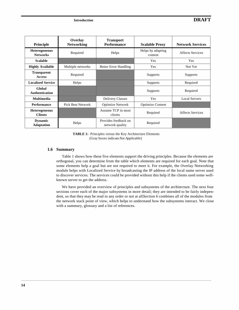
Table 1 shows how these five elements support the driving principles. Because the elements areorthogonal, you can determine from the table which elements are required for each goal. Note thatsome elements help a goal but are not required to meet it. For example, the Overlay Networkingmodule helps with Localized Service by broadcasting the IP address of the local name server usedto discover services. The services could be provided without this help if the clients used some well-known server to get the address.
We have provided an overview of principles and subsystems of the architecture. The next foursections cover each of the major subsystems in more detail; they are intended to be fairly indepen-dent, so that they may be read in any order or not at all. Section 6 combines all of the modules fromthe network stack point of view, which helps to understand how the subsystems interact. We closewith a summary, glossary and a list of references.
TABLE 1: Principles versus the Key Architecture Elements(Gray boxes indicate Not Applicable)
PrincipleOverlay
NetworkingTransport
Performance Scalable Proxy Network ServicesHeterogeneous
Networks Required Helps Helps by adapting content Affects Services
Scalable Yes Yes
Highly Available Multiple networks Better Error Handling Yes Not Yet
Transparent Access Required Supports Supports
Localized Service Helps Supports Required
GlobalAuthentication Supports Required
Multimedia Delivery Classes Yes Local Servers
Performance Pick Best Network Optimize Network Optimize Content
Heterogeneous Clients
Assume TCP in most clients Required Affects Services
DynamicAdaptation Helps Provides feedback on
network quality Required
Overlay Networking DRAFT
15
2 Overlay Networking
In this section we describe the work that our group has done in implementing mobility supportin Overlay Networks. This includes a Vertical Handoff system that enables mobility between heter-ogeneous wireless networks. We present an overview of the basic system, enhancements to thebasic system for low-latency handoffs, and point out differences between our system and IETFMobile IP.
2.1 Overview
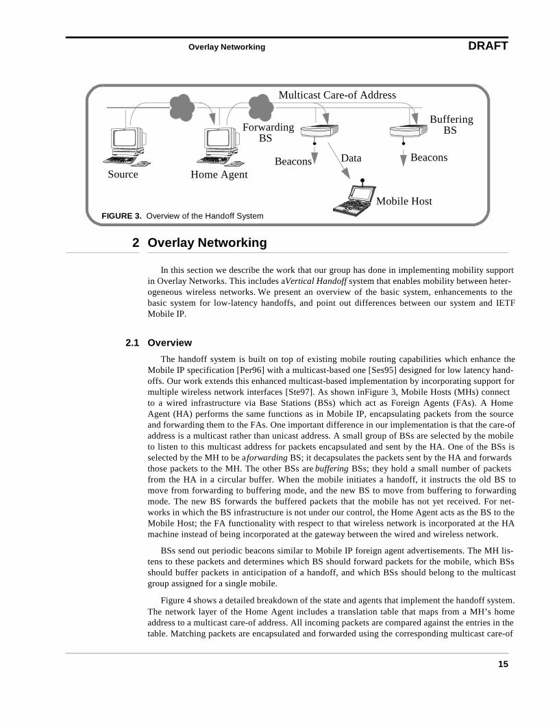
The handoff system is built on top of existing mobile routing capabilities which enhance theMobile IP specification [Per96] with a multicast-based one [Ses95] designed for low latency hand-offs. Our work extends this enhanced multicast-based implementation by incorporating support formultiple wireless network interfaces [Ste97]. As shown in Figure 3, Mobile Hosts (MHs) connectto a wired infrastructure via Base Stations (BSs) which act as Foreign Agents (FAs). A HomeAgent (HA) performs the same functions as in Mobile IP, encapsulating packets from the sourceand forwarding them to the FAs. One important difference in our implementation is that the care-ofaddress is a multicast rather than unicast address. A small group of BSs are selected by the mobileto listen to this multicast address for packets encapsulated and sent by the HA. One of the BSs isselected by the MH to be a forwarding BS; it decapsulates the packets sent by the HA and forwardsthose packets to the MH. The other BSs are buffering BSs; they hold a small number of packetsfrom the HA in a circular buffer. When the mobile initiates a handoff, it instructs the old BS tomove from forwarding to buffering mode, and the new BS to move from buffering to forwardingmode. The new BS forwards the buffered packets that the mobile has not yet received. For net-works in which the BS infrastructure is not under our control, the Home Agent acts as the BS to theMobile Host; the FA functionality with respect to that wireless network is incorporated at the HAmachine instead of being incorporated at the gateway between the wired and wireless network.
BSs send out periodic beacons similar to Mobile IP foreign agent advertisements. The MH lis-tens to these packets and determines which BS should forward packets for the mobile, which BSsshould buffer packets in anticipation of a handoff, and which BSs should belong to the multicastgroup assigned for a single mobile.
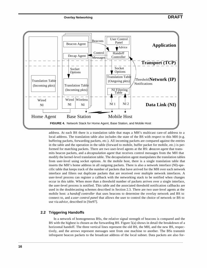
Figure 4 shows a detailed breakdown of the state and agents that implement the handoff system.The network layer of the Home Agent includes a translation table that maps from a MH’s homeaddress to a multicast care-of address. All incoming packets are compared against the entries in thetable. Matching packets are encapsulated and forwarded using the corresponding multicast care-of
Source Home Agent
BSBS
Multicast Care-of Address
ForwardingBuffering
Data
Mobile Host
BeaconsBeacons
FIGURE 3. Overview of the Handoff System
Overlay Networking DRAFT
16
address. At each BS there is a translation table that maps a MH’s multicast care-of address to alocal address. The translation table also includes the state of the BS with respect to this MH (e.g.buffering packets, forwarding packets, etc.). All incoming packets are compared against the entriesin the table and the operation in the table (forward to mobile, buffer packet for mobile, etc.) is per-formed for matching packets. There are two user-level agents at the BS: a beacon agent that trans-mits beacon packets, and a decapsulation agent that receives control messages from the MH thatmodify the kernel-level translation table. The decapsulation agent manipulates the translation tablesfrom user-level using socket options. At the mobile host, there is a single translation table thatinserts the MH’s home address in all outgoing packets. There is also a network interface (NI)-spe-cific table that keeps track of the number of packets that have arrived for the MH over each networkinterface and filters out duplicate packets that are received over multiple network interfaces. Auser-level process can register a callback with the networking stack to be notified when changesoccur in this table. When more than a threshold number of packets arrives over a single interface,the user-level process is notified. This table and the associated threshold notification callbacks areused in the doublecasting schemes described in Section 2.3. There are two user-level agents at themobile host: a handoff controller that uses beacons to determine the overlay network and BS toconnect to, and a user control panel that allows the user to control the choice of network or BS touse via advice, described in [Ste97].
2.2 Triggering Handoffs
In a network of homogeneous BSs, the relative signal strength of beacons is compared and theBS with the highest is chosen as the forwarding BS. Figure 5(a) shows in detail the breakdown of ahorizontal handoff. The three vertical lines represent the old BS, the MH, and the new BS, respec-tively, and the arrows represent messages sent from one machine to another. The BSs transmitinfrequent beacon packets to the broadcast address of the local subnet. Data packets are also for-
Translation Table
Beacon Agent
Decap Agent
SocketOptions
(Incoming pkts)
WiredNI
WirelessNI
Translation Table Translation Table
User Control
Handoff
Beacons
ControlMessages
NI Filtering
ThresholdNotifications
Home Agent Base Station Mobile Host
SocketOptions
(Incoming pkts)
NI 1 NI 2
(Outgoing pkts)
Table
Panel
Controller
Application
Transport (TCP)
Network (IP)
Data Link (NI)Wired
NI
Advice
FIGURE 4. Network Stack for Home Agent, Base Station, and Mobile Host

Overlay Networking DRAFT
17
warded from the old BS. At some point, the signal strength of the new BS is greater than that of theold BS, and the MH initiates a handoff to the new BS. It instructs the new BS to stop bufferingpackets and start forwarding packets to the MH. The MH also instructs the old BS to stop forward-ing packets and start buffering packets. In the homogeneous handoff system, the handoff latency ismeasured from the time the mobile decides that the new BS has a larger signal strength until thefirst data packet arrives from it.
In our system, while a MH roams within the cells that comprise a single overlay, handoffs hap-pen just as in the original system. The MH uses a channel-specific metric to compare different BSsand connects to the best one according to that metric. This allows the horizontal handoff system tooperate seamlessly underneath the vertical handoff system. For an overlay network that handlesmobility directly (for example, CDPD [CDPD] or Metricom’s Ricochet [Ricochet] network), oursystem does nothing and lets that network make all mobility decisions.
Figure 5(b) shows the breakdown of a typical vertical handoff. An upward handoff is initiatedwhen several beacons from the current overlay network are not received. The MH decides that thecurrent network is unreachable and hands over to the next higher network. Even though the MHcannot directly hear the old overlay network, it must still instruct the BS of the old overlay to stopforwarding packets. This request is routed through the new BS. The arrows represent the logicalendpoints of a message, not the path that the message takes from source to destination. Downwardvertical handoffs are initiated when several beacons are heard from a lower overlay’s NI. The MHdetermines that the mobile is now within range of the lower overlay’s NI and switches to the loweroverlay. The handoff starts when the lower overlay becomes reachable or unreachable, and endswhen the first data packet forwarded from the new overlay network arrives at the MH. As previ-ously mentioned, our system only depends on the presence or absence of packets to make verticalhandoff decisions.
OldBS
NewBS
MH
“StopForwarding”
“StartForwarding”
Late
ncy
Han
doff
FIGURE 5. (a) Breakdown of Horizontal Handoff
= Data Packet= Beacon Packet
(Weak)(Strong)
(Strong)(Weak)
= Handoff Message
“StopForwarding”
“StartForwarding”
Late
ncy
Han
doff
FIGURE 5. (b) Breakdown of Basic UpwardVertical Handoff
Old Overlay New OverlayMH
(via new BS)
Overlay Networking DRAFT
18
2.3 Techniques for Low-Latency Vertical Handoffs
One of the goals in our handoff system is to support interactive multimedia communicationacross multiple network interfaces, and for these applications, a latency measured in seconds isunacceptable. Even for non-real time applications such as non-interactive file transfers and WWWbrowsing, a latency of several seconds will lead to a loss of multiple data segments. Previous workhas also shown that packet losses during handoff has detrimental effects on reliable transport proto-cols such as TCP [Cac95]. With this in mind, we examined several enhancements to the base strat-egy that allow us to reduce handoff latency.
2.3.1 Hints for Enabling Enhancements
The schemes described in this section are used in situations where the application indicates thata low handoff latency (less than 300-500ms) is important, such as real time interactive voice orvideo. Even when an application indicates that low-latency handoff is important, these enhance-ments are not used continuously, because of bandwidth/power overheads. They are used only whenthe mobile is in a situation where it may hand off soon. Note that this is not the same as determiningthat a mobile must hand off immediately (i.e., the mobile is now disconnected). Alternative hintscan be used to predict that a handoff is likely. These include
• User input: The user can instruct the MH to be more aggressive about handoff byusing these enhancements. When the user is likely to leave the building, she canput the MH in a mode that uses these enhancements. The user can take the MH outof this state when not moving.
• Received signal strength: Although signal strength indicators, when present, maynot be a good indicator of imminent handoff, they do well at indicating the distancebetween a MH and BS. When a MH notices that the signal strength is graduallydecreasing it can assume that the user is moving away from a BS, and when thesignal strength is increasing a MH can assume that the user is moving toward a BS.When the best BS that a MH can hear has a low signal strength that has beendecreasing, a MH can assume that a vertical handoff may be likely and start usingsome of these enhancements.
• Geographic hints: We can use traces to predict which cells are the gateways to anew overlay network. Although the overlapping nature of wireless overlays meansthat a user can be potentially connected to multiple networks at once, the transi-tions between networks are a function of the building geography. A vertical hand-off is only possible from certain places in the building, and only certain cells coverthese locations (e.g. only one in-building RF cell is likely to cover the exit of anoffice building). The BSs covering these cells could add information in their bea-con packets indicating that this cell is near the exit to a building, and that a verticalhandoff to a wide-area network is likely.
• Handoff Frequency: The MH can also track the frequency of handoffs and usethese enhancements when more handoffs are occurring, indicating that movementout of this overlay’s coverage is more likely. This approach has been suggested forswitching between high-tier and low-tier PCS systems [Tek91].
• Missing a single beacon: We mentioned in Section 2.2 that the MH waits for multi-ple beacon packets before determining that an overlay is (un)reachable and switch-ing to a new overlay. The MH could turn on some of these optimizations aftermissing a single beacon packet, as an attempt to verify that an overlay is (un)reach-able.
Overlay Networking DRAFT
19
2.3.2 Enhancements
We can make the following enhancements to reduce handoff latency. All of these enhancementshave some additional cost in terms of power or overhead bandwidth.
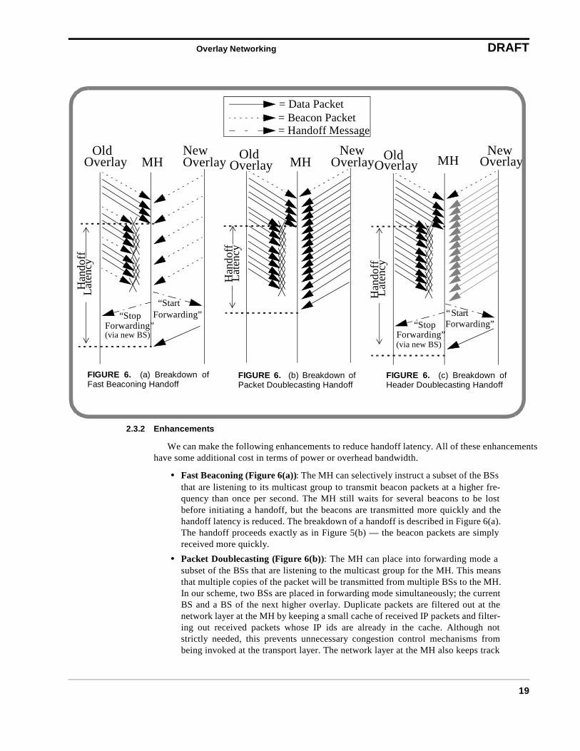
• Fast Beaconing (Figure 6(a)): The MH can selectively instruct a subset of the BSsthat are listening to its multicast group to transmit beacon packets at a higher fre-quency than once per second. The MH still waits for several beacons to be lostbefore initiating a handoff, but the beacons are transmitted more quickly and thehandoff latency is reduced. The breakdown of a handoff is described in Figure 6(a).The handoff proceeds exactly as in Figure 5(b) — the beacon packets are simplyreceived more quickly.
• Packet Doublecasting (Figure 6(b)): The MH can place into forwarding mode asubset of the BSs that are listening to the multicast group for the MH. This meansthat multiple copies of the packet will be transmitted from multiple BSs to the MH.In our scheme, two BSs are placed in forwarding mode simultaneously; the currentBS and a BS of the next higher overlay. Duplicate packets are filtered out at thenetwork layer at the MH by keeping a small cache of received IP packets and filter-ing out received packets whose IP ids are already in the cache. Although notstrictly needed, this prevents unnecessary congestion control mechanisms frombeing invoked at the transport layer. The network layer at the MH also keeps track
Overlay Overlay
“StopForwarding”
“StartForwarding”
Late
ncy
Han
doff
FIGURE 6. (a) Breakdown ofFast Beaconing Handoff
Old NewMH
= Data Packet= Beacon Packet= Handoff Message
(via new BS)
Overlay
Late
ncy
Han
doff
FIGURE 6. (b) Breakdown ofPacket Doublecasting Handoff
Old NewMHOverlay Overlay Overlay
“StopForwarding”
“StartForwarding”
Late
ncy
Han
doff
FIGURE 6. (c) Breakdown ofHeader Doublecasting Handoff
Old NewMH
(via new BS)
Overlay Networking DRAFT
20
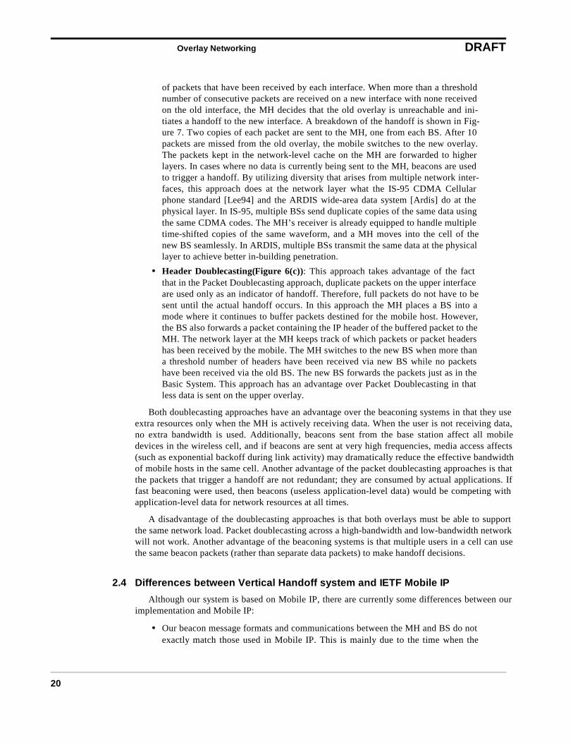
of packets that have been received by each interface. When more than a thresholdnumber of consecutive packets are received on a new interface with none receivedon the old interface, the MH decides that the old overlay is unreachable and ini-tiates a handoff to the new interface. A breakdown of the handoff is shown in Fig-ure 7. Two copies of each packet are sent to the MH, one from each BS. After 10packets are missed from the old overlay, the mobile switches to the new overlay.The packets kept in the network-level cache on the MH are forwarded to higherlayers. In cases where no data is currently being sent to the MH, beacons are usedto trigger a handoff. By utilizing diversity that arises from multiple network inter-faces, this approach does at the network layer what the IS-95 CDMA Cellularphone standard [Lee94] and the ARDIS wide-area data system [Ardis] do at thephysical layer. In IS-95, multiple BSs send duplicate copies of the same data usingthe same CDMA codes. The MH’s receiver is already equipped to handle multipletime-shifted copies of the same waveform, and a MH moves into the cell of thenew BS seamlessly. In ARDIS, multiple BSs transmit the same data at the physicallayer to achieve better in-building penetration.
• Header Doublecasting(Figure 6(c)): This approach takes advantage of the factthat in the Packet Doublecasting approach, duplicate packets on the upper interfaceare used only as an indicator of handoff. Therefore, full packets do not have to besent until the actual handoff occurs. In this approach the MH places a BS into amode where it continues to buffer packets destined for the mobile host. However,the BS also forwards a packet containing the IP header of the buffered packet to theMH. The network layer at the MH keeps track of which packets or packet headershas been received by the mobile. The MH switches to the new BS when more thana threshold number of headers have been received via new BS while no packetshave been received via the old BS. The new BS forwards the packets just as in theBasic System. This approach has an advantage over Packet Doublecasting in thatless data is sent on the upper overlay.
Both doublecasting approaches have an advantage over the beaconing systems in that they useextra resources only when the MH is actively receiving data. When the user is not receiving data,no extra bandwidth is used. Additionally, beacons sent from the base station affect all mobiledevices in the wireless cell, and if beacons are sent at very high frequencies, media access affects(such as exponential backoff during link activity) may dramatically reduce the effective bandwidthof mobile hosts in the same cell. Another advantage of the packet doublecasting approaches is thatthe packets that trigger a handoff are not redundant; they are consumed by actual applications. Iffast beaconing were used, then beacons (useless application-level data) would be competing withapplication-level data for network resources at all times.
A disadvantage of the doublecasting approaches is that both overlays must be able to supportthe same network load. Packet doublecasting across a high-bandwidth and low-bandwidth networkwill not work. Another advantage of the beaconing systems is that multiple users in a cell can usethe same beacon packets (rather than separate data packets) to make handoff decisions.
2.4 Differences between Vertical Handoff system and IETF Mobile IP
Although our system is based on Mobile IP, there are currently some differences between ourimplementation and Mobile IP:
• Our beacon message formats and communications between the MH and BS do notexactly match those used in Mobile IP. This is mainly due to the time when the
Overlay Networking DRAFT
21
Horizontal handoff system was implemented (in parallel to the formalization of theMobile IP specification).
• Our system assumes trust between MHs, FAs, and HAs. As a result, our implemen-tation does not implement the MH-HA and MH-FA authenticators described in[Per96].
• The care-of-address in our system is a multicast address, so there is no explicitcommunication between the FA and the HA.
The above differences could easily be resolved by making our implementation conform to theMobile IP one (i.e. changing message formats, adding functionality, etc.). There are some differ-ences, however, that cannot be resolved easily:
• Because of the optimizations we use for low-latency vertical handoffs, there areextra communication types between MHs and FAs (i.e. forward packet headers,beacon faster, etc.) which cannot be expressed only using Mobile IP messages.
• Although the policy that the MH uses for initiating handoffs is not explicitly spec-ifcied in Mobile IP, our policy for Vertical Handoffs is significantly different thanthe policy that most Horizontal Handoff systems use. We describe these differencesin more detail in [Ste97].
2.5 Overlay Networking Summary
Overlay networking allows a mobile device to detect new networks and to switch to the bestavailable network as the user moves around. Combined with the fast handoff optimizations, thisprovides fast, transparent access to the best network.
Figure 7 summarizes the performance of the basic handoff system and each of the enhance-ments for each of the upward vertical handoffs. We have learned the following things about theenhancements proposed to reduce handoff latency:
• Fast beaconing results in a decrease in latency proportional to the bandwidth over-head. This approach consumes bandwidth whether or not data is being sent to themobile device.
FIGURE 7. Comparison of Handoff Latency for BasicSystem and Enhancements
Overlay Networking DRAFT
22
• Packet doublecasting results in a loss-free zero latency handoff, but at a prohibitivecost.
• Header doublecasting results in a latency similar to the packet doublecastingscheme, but with a dramatic decrease in overhead.
• For handoffs between in-building and wide-area overlays, doublecastingapproaches have limited effect due to the latency-bound nature of the wide-areanetwork we used.
For the network interfaces in our overlay network structure, header doublecasting performs thebest for transitions between in-room and in-building networks, and beaconing works best for transi-tions between in-building and wide-area networks.
By providing seamless coverage to mobile clients as they roam in an Overlay Network structureconsisting of heterogeneous networks, the overlay networking subsystem meets the previouslydescribed principles of Scalability, Transparent Access , and support for Heterogeneous Net-works. By using optimizations to keep handoff latency low, we also meet the principles of Multi-media support and high Performance .
Reliable Data Transport Performance DRAFT
23
3 Reliable Data Transport Performance
A mobile networking environment presents several challenges to the problem of efficient reli-able data transport. In this section, we discuss the challenges posed by the presence of differenttypes of wireless links, and then present our solutions to them. In this discussion, data transportrefers to the transfer of bytes end-to-end, i.e. from a source host to a destination host. The perfor-mance of data transport can be quantified using several metrics such as throughput, goodput,latency and fairness. Given the emphasis on end-to-end transfer of data (which is, after all, whatreally matters to an end user), it is clear that any link (or subnetwork) in path from source to desti-nation has the potential to influence performance. In practice, performance is determined primarilyby the weakest link in the chain. As we elaborate in the remainder of this section, a mobile subnet isoften such a weakest link in the chain.
The de-facto standard protocol for reliable data transport in the Internet is TCP[rfc1123,Ste94].TCP provides a reliable byte-stream abstraction to the higher layers, delivering bytes in-order to theapplication. It achieves reliability by using cumulative acknowledgements (acks), which are sent bythe recveiver to the sender for all received data on a regular basis. These acks are used by thesender to determine the successful delivery or loss of data. In addition to this error control, TCPuses these regular acknowledgements to pace out new data at a consistent rate, a procedure calledack clocking [Jacobson88]. In the absence of any a priori knowledge of the state of the network,TCP uses the rate at which acks arrive to deduce what rates can be sustained on that connection.Therefore any irregularity in the acknowledgement stream gets manifested in the data stream in theimmediate future. To avoid overwhelming the network, TCP performs congestion control by gradu-ally opening its transmission window through the slow start and linear growth phases, and cuttingback its window by half or more when data loss happens. An implicit assumption here is that dataloss is caused by congestion, a valid assumption in traditional wired networks.
Many of the assumptions that TCP makes break down in mobile subnets that have differentkinds of wireless links. First, wireless links tend to be error-prone, resulting in bit-errors. This is theresult of interfering noise due to other wireless transmissions and/or self-interference (fades) due toreflections from physical objects in the environment. Wireless losses make TCP’s assumption, thatdata loss is always due to congestion, invalid, and often result in degraded end-to-end performance.Therefore, it is desirable to shield TCP from such losses, or make it aware of different types of net-work losses, in order to obtain good performance in networks with wireless links. Also, since themobile subnet with its wireless links tends to be located at the periphery of the internetwork, it isoften desirable to employ a local solution that does not impact the rest of the network. These con-siderations motivate our work on a transport-aware reliable link-layer protocol, called the snoopprotocol, described in Section 3.1.
A second problem arises due to network asymmetry. Due to technological and economic con-siderations, it is typically much easier to have a high bandwidth and more reliable link going from acentral base station to mobile nodes (the forward direction) than in the opposite (reverse) direction.In terms of bandwidth, the extent of asymmetry can range from 1:10 ro 1:1000. Examples of suchnetworks include broadband satellite or LMDS-based forward channels coupled with a dialupreverse channel, say using the cellular phone or packet radio network. Another form of asymmetry,called latency asymmetry, arises due to the nature of the media-access protocols in several packetradio networks, and results in large and variable delays. In both these cases, the process of transfer-ring data in one direction is significantly influenced by the traffic in the opposite direction. The netresult of each of these forms of asymmetry in the context of TCP is that ack clocking gets dis-rupted, thereby resulting in degraded performance. Our approach to mitigating this problemencompasses both techniques that operate end-to-end and those that operate just locally in the wire-
Reliable Data Transport Performance DRAFT
24
less subnet. As we discuss in Section 3.2, it is possible to use either approach to achieve similarperformance benefits.
The third problem that we address arises due to the characteristics of the media-access control(MAC) protocol used in wireless networks, especially wireless LANs. The MAC protocol used insuch networks are derived from the corresponding protocols used in wired networks. However,wireless networks are different from wired networks in certain important ways, which could signif-icantly impact data transport performance. For example, it is difficult to do collision detection inwireless networks. Also, the quality of connectivity could be significantly different for eachreceiver at the same point in time. Our approach to addressing these problems is XXX Giao, pleasecomplete
XXX incorporate this into previous paragraph Finally, in the context of improving network per-formance, we also discuss the issues of link sharing in wireless local area networks. The goal oflink sharing is to provide a controlled bandwidth allocation for mobile hosts and their applications,and thus improving the scalability of the network. TCP performance would benefit from such amechanism because of the stable link usage in the wireless hop provided by link sharing.
In summary, our approach to improving data transport performance in mobile, wireless net-works has been identifying the specific characteristics of such networks (e.g., errors vs. congestion,asymmetry, unfairness, etc.) that impact TCP performance and then incorporating end-to-end aswell as local mechanisms to either make TCP adapt better to these characteristics or to hide themfrom TCP. By focusing on TCP, we are able to make our solutions applicable to the vast collectionof applications on the Internet that use TCP, and help in integrating wireless technologies into theglobal Internet.
3.1 The Snoop Protocol
Over the past several years, TCP has been tuned to perform well in traditional networks madeup of links with very low bit-error rates. Networks with higher bit-error rates, such as those withwireless links and mobile hosts, violate many of the assumptions made by TCP, causing degradedend-to-end performance. In particular, packet losses are assumed by TCP to be due to congestion,rather than because of errors or user mobility, and this causes the invocation of congestion controlmechanisms (e.g., slow start [Jac88]) that decrease the sender’s congestion window and reducethroughput.
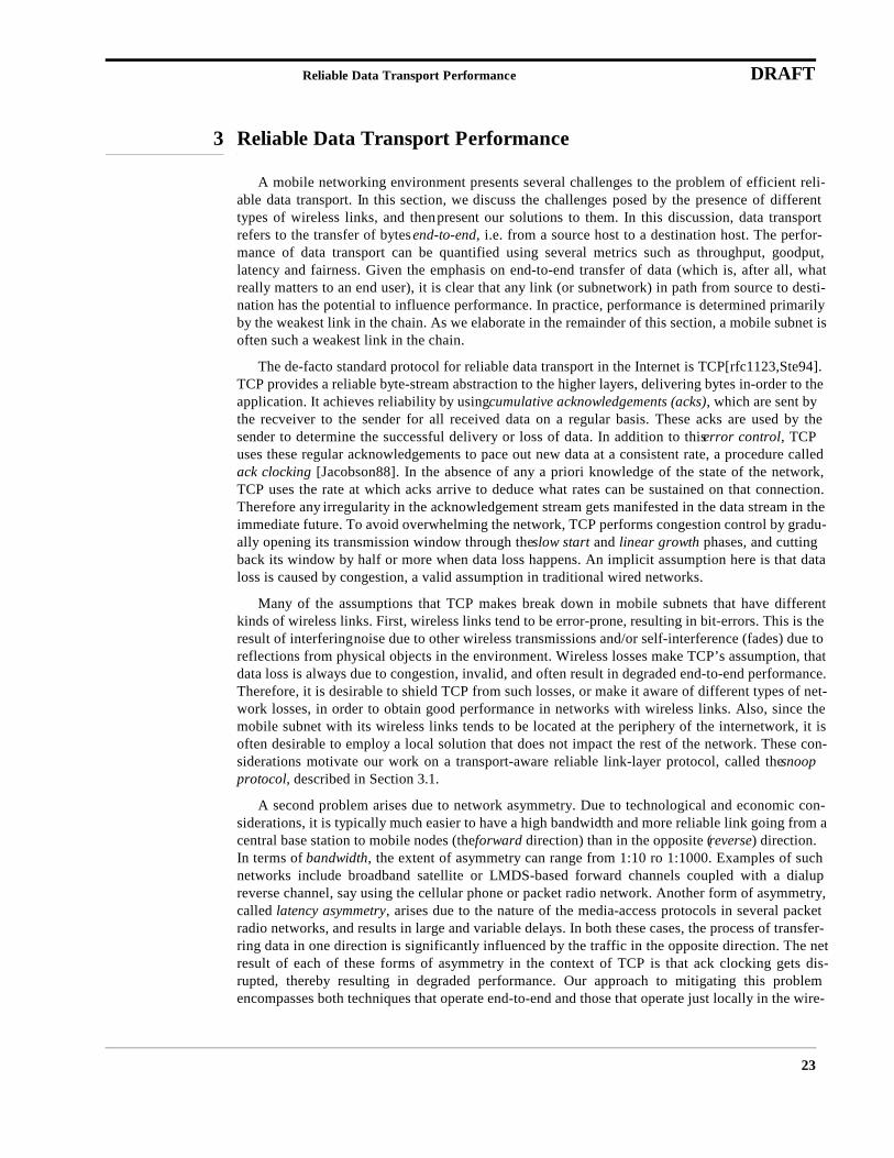
The snoop protocol is a localized protocol that modifies the networking software only at thebase station and at the mobile host connected over the wireless link. In particular, no modifications
Wired network
Fixed Host
Base Station
Mobile Host
Figure 1. Network topology of the single-hop cellular wireless network based on the WaveLAN. The snoop agent runs at the base stations in the network.
Base Station
Home Agent
(Snoop) (Snoop)

Reliable Data Transport Performance DRAFT
25
are required to TCP implementations elsewhere in the Internet. The protocol works by deploying anagent called the snoop agent at the base station. The agent mainly performs the functions of lossdetection and loss recovery via local retransmissions. The network topology and snoop agent loca-tion are shown in Figure XXX.
For transfer of data from a fixed host to a mobile host, we make modifications only at the basestation. These modifications include caching unacknowledged TCP segments and performing localretransmissions based on a few policies that depend on TCP acknowledgments from the mobilehost and timeouts of locally-maintained timers. By using duplicate acknowledgments to quicklyidentify packet loss, performing local retransmissions as soon as data loss is detected, and suppress-ing these duplicate acknowledgments from the TCP sender, the snoop agent shields the sender fromthe vagaries of the wireless link. In particular, transient situations of very low communication qual-ity and temporary disconnectivity are completely hidden from the sender.
For transfer of data from a mobile host to a fixed host, the snoop agent detects missing packetsat the base station by snooping on packets arriving from the mobile host and identifying holes in thetransmission. Then, when it sees duplicate acknowledgments arriving from the receiver that signi-fies a loss of this packet, it sets a bit in its TCP header and forwards it to the mobile sender. Thesender uses this Explicit Loss Notification (ELN) bit to identify that the loss was unrelated to con-gestion, and retransmits the packet without taking any congestion-control actions. This requiresmodifications to both the base station and mobile hosts.
A key design goal in this work is the use of only soft state in the protocol. The state maintainedby the snoop protocol is soft, implying that its loss or corruption does not impact the correct func-tioning of the protocol. We achieve this by taking advantage of the fact that TCP acknowledgmentsare cumulative, which makes it easy to regenerate and periodically refresh any out-of-date state.The snoop protocol should be viewed strictly as a performance improvement, which greatlyimproves the performance of TCP over single-hop wireless networks. If the state associated withthe protocol is lost, it can be rebuilt rather easily upon the arrival of the next packet and acknowl-edgment.
The mechanisms described above together improve the performance of connections in bothdirections, without sacrificing any of the end-to-end semantics of TCP or modifying host TCP codein the fixed network. This combination of greatly-improved end-to-end performance, preservationof end-to-end semantics, and purely local recovery techniques is the main contribution of this work.
Reliable Data Transport Performance DRAFT
26
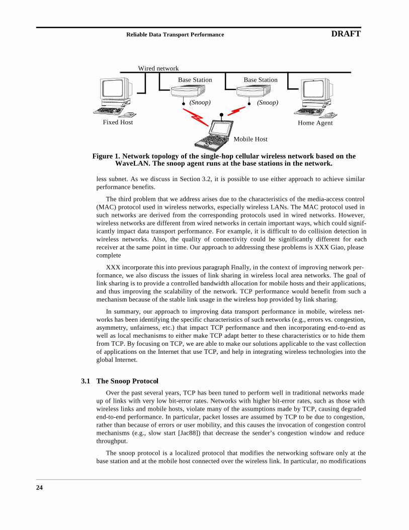
We have implemented a prototype version of the snoop protocol on a wireless testbed consistingof IBM ThinkPad laptops and Pentium PC basestations communicating over a 2 Mbps AT&TWavelan. Our experiments show that it is significantly more robust at dealing with unreliable wire-less links as compared to normal TCP; we have achieved speedups of between 2 and 20 comparedto regular TCP in our experiments with the protocol over a WaveLAN link across a range of simu-lated bit-error rates, as shown in Figure XXX. We have also performed an extensive performanceevaluation of the snoop protocol by implementing several other schemes (including other flavors oflink-layer protocols, end-to-end protocols and split-connection protocols) and comparing their rela-tive performance [BPSK96]. Our results demonstrate the significant benefits and advantages ofsuch transport-aware link layer schemes, in addition to demonstrating the effectiveness of ELN andselective acknowledgments in handling non-congestion-related packet losses.
We have also integrated the multicast-based low-latency handoff scheme described in Section 2with the snoop protocol for improved TCP performance in the presence of both wireless bit-errorsand user mobility between cells. The idea is to take advantage of the multicast and intelligent buff-ering at the base stations (used to achieve low handoff latencies) in order to perform the mirroringof the snoop agent’s soft state as well. Further details
3.2 Asymmetric Networks
As mentioned in the previous section, TCP relies on the ack clocking mechanism to inject newdata into the network at an even pace. In effect, TCP depends on the smooth flow of packets (acks)in the opposite direction in order to sustain good data transport performance in a certain direction.While this dependence in fact leads to robust congestion control in most wired networking scenar-ios, it can result in degraded performance in networks that exhibit asymmetry, such as many wire-less networks.
Given our focus on TCP, we have the following characterization of network asymmetry: a net-work is said to exhibit asymmetric characteristics with respect to TCP, if the data transport perfor-mance in one direction is affected significantly by the traffic and network charcteristics in the
Figure 2. Throughput received by the mobile host at different bit-error rates (log2 scale). The vertical error bars show the standard deviations of the receiver throughput.
Bit Error Rate-1 (1 error every x bits, on average)
Rec
eive
r T
hrou
ghpu
t (M
b/s)
0
0.2
0.4
0.6
0.8
1
1.2
1.4
1.6
64Kb 128Kb 256Kb 512Kb 1Mb 2Mb 4Mb 8Mb No Errors
SnoopRegular TCP

Reliable Data Transport Performance DRAFT
27
opposite direction. Note that the traffic in the opposite (reverse) direction could just be the TCPacks for data in the forward direction.
This general definition leads to several types of asymmetry that we can classify:
• Bandwidth: The bandwidth in the forward direction (towards the end user) is much larger (10 to 1000 times larger) than that in the reverse direction (away from the user). Networks based on Direct Broadcast Satellite (DBS) systems or wireless cable modem technology exhibit such asymmetry.
• Latency: In certain wireless networks, such as Cellular Digital Packet Data (CDPD), the underlying media access control (MAC) protocol often results in a significantly larger one-way latency from a base station to a mobile station than in the reverse direction. In other networks, such as the Metricom Ricochet multi-hop wireless network, there is a significant delay when a node switches from sending to receiving mode or vice versa, a phenomenon that is exacerbated in the poresence of bi-directional traffic (e.g., caused by TCP acks). This often results in significant variations in round-trip times and makes it hard for TCP to adapt to the characteris-tics of the network.
• Bit-error rates: The incidence of packet errors could be much greater in the upstream direction than in the downstream direction. This could be inherent in the network technology (e.g., a 2-way cable modem system) or the result of distinct upstream and downstream technologies (e.g., a DBS downlink with a packet radio uplink).
We observe that the reason for the development and deployment of asymmetric network accesstechnologies is in part due to technological and economic considerations that make it easier to pro-vide a fast and reliable channel out from a central base station than in the opposite direction, and inpart because of the asymmetric communications requirements of today’s popular applications suchas Web access.
We identify three specific problems that network asymmetry results in as far as TCP perfor-mance is concerned. We discuss both end-to-end techniques (i.e., enhancements to TCP) and localtechniques to alleviating these problems, which are generally applicable across a variety of net-works that exhibit asymmetric characteristics.
First, the ack stream corresponding to a data transfer could either lead to congestion over thebandwidth-contrained reverse channel thereby disrupting the flow of data packets indirectly (due tothe breakdown of ack clocking) or interfere directly with the flow of data packets (as in a packetradio network). Our basic solution to this problem is to decrease the frequency of acks transmittedby the TCP receiver. Our end-to-end scheme, called ack congestion control, allows the receiver toadaptively reduce the frequency of acks, while ensuring that the sender is not starved of acks. Thisrequires the TCP sender to tell the receiver how large its window is. Our local scheme, called ackfiltering, operates at the router to the constrained reverse channel. It exploits the cumulative natureof TCP acks to filter out redundant acks from the queue when a new ack for the same connectionarrives at the input to the queue.
However, the decreased frequency of acks leads to problems at the TCP sender. Since each newack could cause the sender’s window to slide forward by several segments, the sender could emit aburst of several packets back-to-back, and induce congestion in routers downstream. In addition,since the TCP sender increments its congestion window based on the number of acks and not onhow many bytes are acknowledged with each ack, window growth could now be much slower. Ourend-to-end mechanism for combating these problems, called sender adaptation, breaks up a poten-tially large burst into several smaller bursts and spaces apart these smaller bursts according to the
Reliable Data Transport Performance DRAFT
28
effective data transfer rate of the connection. Our local solution, called ack reconstruction, hidesthe infrequent ack stream from the TCP sender by deploying an agent at the other end of the con-strained reverse channel. Once the acks have traversed the constrained network, the ack reconstruc-tor attempts to reconstruct the original smooth ack stream by inserting new acks to fill in gaps andby spacing apart acks that have been bunched-up. The end result is that an unmodified TCP sendercan continue to rely on standard ack clocking to sustain the data transfer at a consistent rate.
The final problem arises specifically in an asymmetric-bandwidth situation where the acks ofthe forward-direction data transfer have to share the constrained reverse channel with a reverse-direction data transfer (simultaneous bi-directional data transfers). With FIFO queuing, the largedata packets of the reverse transfer could block the transmission of acks for long periods of time,thereby starving the sender of the forward transfer. Our local solution to this problem, called acks-first scheduling, involves giving acks a strictly higher priority than data packets. The rationale isthat the small acks packets when sent infrequently would have little impact on the performance ofthe reverse data transfer, but their timely transmission is critical to sustaining good performance forthe forward data transfer. Since the resolution of this problem requires control over the schedulingof data and acks at the reverse bottleneck link, we do not have an end-to-end version of the solu-tion.
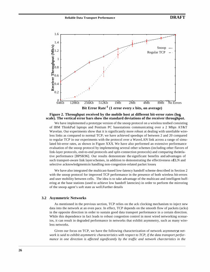
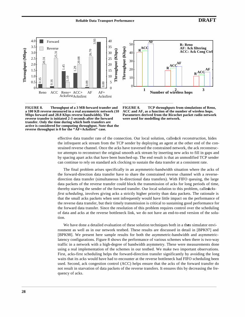
We have done a detailed evaluation of these solution techniques both in a the ns simulator envi-ronment as well as in our network testbed. These results are discussed in detail in [BPK97] and[BPK98]. We present here sample results for both the asymmetric-bandwidth and asymmetric-latency configurations. Figure 8 shows the performance of various schemes when there is two-waytraffic in a network with a high-degree of bandwidth asymmetry. These were measurements doneusing a real implementation of the schemes in our testbed. We make two important observations.First, acks-first scheduling helps the forward-direction transfer significantly by avoiding the longwaits that its acks would have had to encounter at the reverse bottleneck had FIFO scheduling beenused. Second, ack congestion control (ACC) helps ensure that the acks of the forward transfer donot result in starvation of data packets of the reverse transfers. It ensures this by decreasing the fre-quency of acks.
Thr
ough
put (
Mbp
s)
Thr
ough
put (
Kbp
s)
0
0.5
1.0
1.5
2.0
2.5
3.0
3.5
4.0
0
5
10
15
20
25
30
35
40
Reno ACC Reno+ ACC+Acksfirst
AF AF+Acksfirst
Forward
Reverse
0.35
20.3
1
0.16
25.3
1
1.45
5.10
1.29
20.0
8
0.09
26.7
03.
93
0.00
Acksfirst
0
10
20
30
40
50
Number of wireless hops1 2 3
Thr
ough
put (
Kbp
s) RACC
AF
RACC
ACCR
AF
AF
R: RenoAF: Ack filteringACC: Ack Cong Ctrl
FIGURE 8. Throughput of a 3 MB forward transfer and a 100 KB reverse measured in a real asymmetric network (10 Mbps forward and 28.8 Kbps reverse bandwidth). The reverse transfer is initiated 2-3 seconds after the forward transfer. Only the time during which both transfers are active is considered for computing throughput. Note that the reverse throughput is 0 for the “AF+Acksfirst” case.
FIGURE 8. TCP throughputs from simulations of Reno, ACC and AF, as a function of the number of wireless hops. Parameters derived from the Ricochet packet radio network were used for modelling the network.
Reliable Data Transport Performance DRAFT
29
Figure 8 shows the performance of various schemes obtained via a simulation of the Ricochetpacket radio network. The important observation is that ack filtering (AF) and to a lesser extent ackcongestion control (ACC) result in improved performance. The reason is that the decrease fre-quency of acks in these cases decreases MAC contention and hence latency variability.
3.3 Link Sharing for Wireless LANs
In this section, we present the designs of a link sharing mechanism in a wireless LAN environ-ment to improve the scalability of such a network. Wireless LANs (WLAN) are placed in the bot-tom layer of the wireless overlay network. They generally provide shared access to a single channel(hundreds of Kbps to a few Mbps) using CSMA based protocols. Examples include the ProximRangeLAN and AT&T WaveLAN[DN95]. The bandwidth provided by a WLAN, while better thanmost other wireless network technologies, is still limited. An effective link sharing mechanism toprovide stable network performance to applications and mobile hosts is important and necessary fora wireless network to accommodate more users and demanding applications. Furthermore, it is alsodesirable for administrative reasons to be able to control the link resource allocation. For example,while providing access to roaming mobile hosts, the owner of a WLAN may want to ensure that thelocal users are given larger slices of the bandwidth.
Essentially, there are two most important goals for an effective WLAN link sharing mechanism.
1. Bandwidth Sharing: A link sharing mechanism’s primary responsibility is to allo-cate bandwidth among mobile hosts and to enforce the allocation.
2. Surplus Bandwidth Distribution: If a mobile host is not using its allocated band-width, the surplus bandwidth should be shared by other mobiles hosts in a con-trolled fashion.
The general issues of link sharing are well discussed in the modeling of Class Based Queueing(CBQ) in [FJ95]. CBQ provides effective hierarchical link-sharing on a point-to-point link, and ithas being implemented in the Trans-Atlantic FAT pipes, among others. However, the multi-accessnature of WLANs requires a distributed link sharing mechanism, which is the subject of the follow-ing discussions. The goal of this study is, quite simply, to extend CBQ to the WLANs.
We base our discussions on WaveLAN, which is a 2 Mbps WLAN. We also assume that allmobile hosts and the base station follows the link sharing protocol. Furthermore, there is no directcommunication among mobile hosts in a WaveLAN.
3.4 Bandwidth Sharing
In this subsection we describe the partitioning of the bandwidth among mobile hosts and theenforcement of such bandwidth sharing guidelines.
Figure 9 shows a hierarchical link sharing structure used for partitioning the bandwidth amongagencies and further among sub-classes of each agency in [SJ95]. We use a similar link sharingstructure, as shown in Figure 10, except the concept of an agency is substituted by a node. A nodeis either a mobile host or a basestation in a WaveLAN. Because both up-stream and down-streamtraffics share the single channel, it is necessary to cover both traffic directions in partitioning band-width.
The enforcement of such a hierarchical bandwidth allocation guideline is performed at two lev-els. Firstly, a node need to ensure that its internal link sharing guideline is followed. Since this

Reliable Data Transport Performance DRAFT
30
requirement is no different from the CBQ goal, the same scheduling algorithms discussed for CBQcan be used.
Secondly, each node needs to get its allocated bandwidth. This is done with a very simplemethod. The basic idea is that if bandwidth is not over-allocated among nodes, and that each noderestrains itself at the link level from using more than its allocated bandwidth, everyone wouldreceive their promised bandwidth share. There is no explicit coordination among nodes for the linkusage, and no state exchange is necessary besides the initial network cell admission and subsequentbandwidth allocation process.
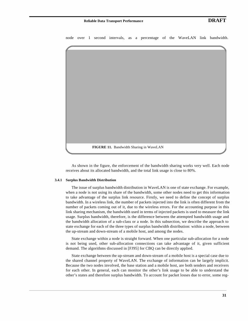
Figure 11 shows a simulation result. In this simulation, there are 9 nodes using a WaveLANlink. One node is sending a CBR stream at 10% of the total link bandwidth, and the packet size is190 byte. All other 8 nodes send random sized packet ranging from 200 byte to 1000 byte. 3 ofthese 8 nodes are allocated 20% of the total link bandwidth each, and the rest 2% each. All these 8nodes have sufficient demand if the bandwidth is available. The line at the top is the total linkusage. The x-axis shows time in seconds. The y-axis shows the average bandwidth used by each
FIGURE 9. Link Sharing Structure for CBQ FIGURE 10. Link Sharing Structure for WLAN
Link
ftpvideo ftpvideo
30%
70%
20%10%40%
30%
agency A agency B
Link
ftp ftpvideo
40%
20%10%40%
20%
node A node BS
40%
video
30%for A for B
node B
Reliable Data Transport Performance DRAFT
31
node over 1 second intervals, as a percentage of the WaveLAN link bandwidth.
As shown in the figure, the enforcement of the bandwidth sharing works very well. Each nodereceives about its allocated bandwidth, and the total link usage is close to 80%.
3.4.1 Surplus Bandwidth Distribution
The issue of surplus bandwidth distribution in WaveLAN is one of state exchange. For example,when a node is not using its share of the bandwidth, some other nodes need to get this informationto take advantage of the surplus link resource. Firstly, we need to define the concept of surplusbandwidth. In a wireless link, the number of packets injected into the link is often different from thenumber of packets coming out of it, due to the wireless errors. For the accounting purpose in thislink sharing mechanism, the bandwidth used in terms of injected packets is used to measure the linkusage. Surplus bandwidth, therefore, is the difference between the attempted bandwidth usage andthe bandwidth allocation of a sub-class or a node. In this subsection, we describe the approach tostate exchange for each of the three types of surplus bandwidth distribution: within a node, betweenthe up-stream and down-stream of a mobile host, and among the nodes.
State exchange within a node is straight forward. When one particular sub-allocation for a nodeis not being used, other sub-allocation connections can take advantage of it, given sufficientdemand. The algorithms discussed in [FJ95] for CBQ can be directly applied.
State exchange between the up-stream and down-stream of a mobile host is a special case due tothe shared channel property of WaveLAN. The exchange of information can be largely implicit.Because the two nodes involved, the base station and a mobile host, are both senders and receiversfor each other. In general, each can monitor the other’s link usage to be able to understand theother’s states and therefore surplus bandwidth. To account for packet losses due to error, some reg-
FIGURE 11. Bandwidth Sharing in WaveLAN
Reliable Data Transport Performance DRAFT
32
ular updates should be used to adjust the state exchange between the two. These updates can besimple and piggybacked on regular data packets to reduce overhead.
State exchange among nodes, however, need to be explicitly conducted. When a mobile host isnot using its combined allocation for up-stream and down-stream link bandwidth, the surplus linkresource should be distributed among other nodes according to certain policy. In this case, the basestation is at the position of collecting up-to-date link usage information, which is already collectedfor the purposed stated in the previous paragraph. It is up to the base station to inform other nodesto adjust their link usage. The central role of the base station is due to two reasons:
1. Administratively, the base station is naturally the one to enforce the WLAN usagepolicy.
2. Because most of the traffic in a WLAN is expected to be heavily biased towards thedownstream traffic, it is really most likely an internal state exchange at the base sta-tion for it to distribute the surplus bandwidth among the other down-stream trafficsof other mobile hosts. This also means that the explicit state exchange from basestation to other mobile hosts is not necessarily frequent or expensive.
3.5 Summary
Taken together, our extensions provide a faster and much more robust version of TCP. Thesemodifications are critical for wireless networks, but are more widely applicable. Thus these exten-tions enable improved performance in heterogeneous networks comprising both wireless and wire-line components.
The Scalable Proxy and Coordination Bus DRAFT
33
4 The Scalable Proxy and Coordination Bus
The proxy’s main tasks are to shield clients from the effects of slow networks and to tailor Inter-net content to the needs of each different client, allowing meaningful content presentation across allclients. As described in detail elsewhere [FGBA96], we have found that datatype-specific lossycompression, which we call distillation, is an effective adaptation mechanism. Distillation provideswell-defined operations over semantically typed data. For example, distillation of an image consistsof selectively discarding color information, high-frequency components, or pixel resolution. Distil-lation of video can additionally include frame-rate reduction. Less obviously, distillation of format-ted text requires discarding some formatting information but preserving the actual prose. In allcases, the goal is to preserve information that has the highest semantic value, if necessary changingits format to enable optimal presentation on the target device.
The user can always explicitly ask for a higher-quality representation of degraded content later,if she decides that the data is valuable enough to be worth the additional latency; for instance,zooming in on a graphic or video frame, or rendering a particular page containing PostScript textand figures without having to render the preceding pages. We define refinement as the process offetching some part (possibly all) of a source object at increased quality, possibly the original repre-sentation. As with distillation, the refinement technique is a function of the semantic type, and theimplementation of the technique requires intimate knowledge of the encoding. For example,“zooming in” is a useful operation for all images regardless of encoding, but encoding-specifictools are necessary to extract and magnify the desired subregion.
Providing distillation and refinement at the proxy confers several architectural advantages.First, it allows a wide range of mobile clients using networks with widely varying characteristics tointeroperate transparently with legacy servers, since all adaptation is performed at the proxy, whichlooks like a powerful, well-connected client from the server’s point of view. Even if we could mod-ify servers, however, performing adaptation at the proxy confers an important separation of con-cerns: the servers focus on content provision, while the proxy focuses on individualized contentpresentation. This separation has the technical benefits of improved maintainability and amortiza-tion of proxy resources, and the economic benefit of orthogonalizing content provision and qualityof service provision, which decouples both administration and billing (distillation and refinementrepresent a value-added service to users with slow network connections or impoverished clients).
In the following subsections, we describe the internal architectural organization of a scalableproxy designed to provide individually-customizable service to each of thousands of users, basedon each user’s personal preferences, client characteristics, and network characteristics. The net-work characteristics can be explicitly supplied (if a “stock” network stack is used) or deduced bythe Sessions layer described in XXXX (if the Dædalus network stack is used). Although the proxyfunctionality is central to our overall architecture, the narrow interfaces used by the proxy (in thiscase, the HTTP proxy interface) enables it to operate as a standalone component without the rest ofthe architecture as well, and in fact we have already deployed Web proxy service to the dialup usercommunities at UC Berkeley and UC Davis using this platform.
4.1 The Coordination Bus
The coordination bus [FJM+95] provides a virtual bus with discrete, symbolically named chan-nels, layered on top of a multicast network. A coordination-bus-aware program can broadcast infor-mation on one or more CB channels as well as hear the broadcasts of other CB-aware programs bylistening on the appropriate channel(s). CB channels can be used for communication between dif-ferent systems or between components of a single distributed system. Our scalable proxy is an
The Scalable Proxy and Coordination Bus DRAFT
34
example of a non-trivial distributed system that uses the CB in both of these ways: various compo-nents of the system use the CB to exchange information used to achieve fault tolerance and auto-matic load balancing. In addition, the “front end” (the part of the system visible to the outsideworld) can be controlled by sending messages on the CB.
The scalable proxy defines the following channels:
GM_PTMBEACON: As described in Section 4.2.3, the PTM sends out periodic beacons so thatworkers and the front end can find it. If the front end detects that the beacons have gone away, itassumes the PTM has died, and attempts to launch a new one.
GM_NETSTATE: The front end can be advised of automatically-detected network changes viathis channel. A network state notification specifies which user(s) the change applies to and the newvalues of the changed network characteristic(s), such as bandwidth and latency.
4.2 The Proxy Architecture
In this section we give a high-level description of the internal architecture of the scalable proxyfor distillation and refinement. A detailed description, including performance information andfault-injection experiments, may be found in [FGC+97]. The proxy is designed to run on a well-connected network of commodity workstations (NOW). Although the core software is considerablymore general, we focus our attention here on the particular mechanisms that allow the scalableproxy to work as an HTTP proxy [Luo94] for the World Wide Web. The design goals of the proxyare as follows:
• High performance: the latency of serving an individual user should be minimized.Ideally, the overhead of using the proxy should be barely noticeable even when ahigh-speed connection is used. This supports Principle 8 (Performance) from theIntroduction.
• Scalability: as the number of users increases, the per-user performance can be heldapproximately constant by adding nodes to the NOW. This supports our goal ofserving thousands and eventually millions of users (Principle 2 from the Introduc-tion).
• High availability: the ability to transparently mask the transient failure of anyindividual component, so that the service as a whole is continuously available.Meeting this design goal is a requirement of Principle 3 (High Availability) fromthe Introduction.
• Mass customization: A persistent preference profile is maintained for each user ofthe proxy. The profile is automatically used to tailor the proxy’s behavior on everyrequest from that user.
We now describe the components of the proxy, which are shown in Figure 12. Note that allcomponents except the Proxy-Transcoder Manager and User Preferences Database are replicatedfor scalability, availability, or both.
4.2.1 The Proxy Front End
All interaction between clients and the proxy occurs through the front end, the only componentvisible to the “outside world”. It is the attachment point to which clients connect for proxy service.Our HTTP proxy implementation is compatible with the W3C protocol standard for HTTP 1.0proxies. The front end matches incoming requests with the appropriate client preferences profile(currently based on the IP address of the request) and handles preference changes for clients. Thefront end does not actually do any of the work of servicing the client requests; therefore, it can be

The Scalable Proxy and Coordination Bus DRAFT
35
simple and fast, maximizing the number of clients that can be served and minimizing the “turn-around time” before a client request is handled
4.2.2 Workers
The workers are code modules that perform the compute-intensive work of distillation andrefinement, caching, and if necessary managing the user interface to the proxy (we discuss UIissues separately below). Our system places minimal requirements of worker structure, making iteasy to use off-the-shelf code. A given NOW node may host one or several workers. The workersare “dumb” in that they specialize only in content transformation; the other aspects of distillation—load balancing across multiple instances of a worker, and determining the correct user preferencesfor a particular distillation operation— occur in other parts of the system, and workers don’t need toknow about them.
In addition to content transformation, workers can also modify the output datatype of the con-tent. For example, if a client cannot display JPEG images, a JPEG worker could produce output ina different format that the client can understand, perhaps even a proprietary optimized image for-mat. If the client can only display images that respect certain constraints (number of colors, fixedcolor palette, maximum area, etc.), the worker can attempt to transform the content such that theconstraints are met. This tremendous flexibility gives the proxy the ability to serve a wide varietyof heterogeneous clients (as we require in Principle 9 from the Introduction), and since each user’spreferences are tracked separately, the specific transformations performed will be user-specific(mass customization). We describe separately a specific example application, Top Gun Wingman,that leverages this capability
Besides distillation, a worker is expected to be able to report two quantities, both of which areused by the Proxy Transcoder Manager (described below) for load balancing:
• Its current workload (e.g., what fraction of the time it has been busy since the lastreport); this information is broadcast using the CB.
• The estimated completion time of a given distillation operation, given the inputs.
FIGURE 12. Block diagram ofscalable proxy internalarchitecture. Most nodes areconnected via both a high-speedSAN (system-area network, suchas Myrinet) connection, and alower-speed “utility network”(such as 10baseT Ethernet) whichalso includes connections to theoutside world. Componentsinclude front ends (FE), a pool ofworkers (W) some of which maybe caches ($), a user profiledatabase, a graphical monitor, anda fault-tolerant load manager,whose functionality logicallyextends into the manager stubs(MS) and worker stubs (WS).
System Area
Wide-Area Network
Manager
GraphicalMonitor
UserProfile DB
Network
$
$
$
Worker Pool
FE FEFEMS MS MS
W
WS WS WS
W W WorkerAPI
The Scalable Proxy and Coordination Bus DRAFT
36
4.2.3 Proxy Transcoder Manager (PTM)
The PTM manages the location of workers, distribution of load across multiple workers, spawn-ing of new workers on demand, and providing the assurance of fault tolerance. In addition, the PTMcan spawn workers of a given type when there is sufficiently increased load and when a NOW nodeis available to host it, or when an existing worker dies because of a program fault.
The functionality of the PTM is split across a centralized manager process and stubs in the fron-tend and workers (the manager stub and worker stub, respectively). The PTM periodically beaconsits existence on a coordination bus channel to which the other components subscribe. The use of thecoordination bus provides a level of indirection and relieves components of having to explicitlylocate each other. When the front end has a task for a worker, the manager stub code in the frontendcontacts the PTM, which locates an appropriate worker, spawning one if necessary. The managerstub caches the new worker’s location for future requests.
The worker stub attached to each worker accepts and queues requests on behalf of the workerand periodically reports load information to the manager. The PTM aggregates load informationfrom all workers, computes weighted moving averages, and piggybacks the resulting informationon ites beacons to the manager stub (at the frontend). The manager stub caches the information inthese beacons and uses lottery scheduling [WW94] to select a worker for each request. If no workerexists to handle the load, the PTM knows how to launch a new one. The PTM can also detect the“death” of a worker and replace it with a new copy.
To allow the system to scale as the load increases, the PTM can automatically spawn new work-ers on unused nodes. Another mechanism used for adjusting to bursts in load is overflow: if all thenodes in the system are used up, the PTM can resort to starting up temporary workers on a set ofoverflow nodes. Once the burst subsides, the workers may be reaped.
The PTM represents a centralized approach to load balancing policy: all load balancing deci-sions are made in the PTM based on information periodically collected from the workers (workers).An alternative design would be fully distributed load balancing, in which workers maintain localload statistics (and possibly exchange statistics with their peers) and the scheduling decision ismade solely on the basis of this local information, rather than in a central “clearinghouse”. Thestandard argument in support of this design is that the loss of an individual worker may lead todegraded scheduling but not loss of functionality, whereas in our scheme the death of the PTMresults in the loss of ability to make scheduling decisions at all. We counter that for our architec-ture, the centralized approach is superior, provided the PTM can be made fault-tolerant, for the fol-lowing reasons:
• Centralized load balancing algorithms are easier to design, easier to understand,easier to debug, and tend to exhibit behavior that is easier to characterize.
• Centralized load balancing allows a flexibility of policy that is much more difficultto achieve with distributed scheduling. For example, during peak usage hours, wecan stratify users into “service classes”, giving users in the higher service classesfaster service (e.g., by directing their requests to a set of “reserved” workers whosewait queues are kept shorter than average). Implementing such policy changes in adistributed scheduler is difficult and requires changing every component that con-tains scheduling logic (i.e. every worker). In our system, we can even transparentlystart a new PTM with a different policy and then kill the old one, without interrupt-ing system operation.
The key to making the PTM fault-tolerant is the use of a process-peer fault tolerance design:when a component fails, one of its peers restarts it (on a different node, if required), while cachedstale state carries the surviving components through the failure. After the component is restarted, it
The Scalable Proxy and Coordination Bus DRAFT
37
gradually rebuilds its soft state. In our system, the PTM and front end act as peers for fault toler-ance. If the PTM dies, the front end will detect this (through the loss of beacons from the PTM) andrestart the PTM. All workers that were originally communicating with the failed PTM will detectthe new PTM and register withit, thereby re-establishing communication and rebuilding the PTM’sstate. Thus the only way to bring the system down is to simultaneously kill the front-end and thePTM. Since these can be made to run on different physical machines, simultaneous death of both isunlikely. Process-peer fault tolerance is one of the techniques used to achieve the High Availabilitygoal of Principle 3 from the Introduction.
4.2.4 Caching
The proxy architecture includes Harvest cache workers [BDH+94] partitioned across severalnodes. Harvest suffers from three functional/performance deficiencies, two of which we resolved.
First, although a collection of Harvest caches can be treated as “siblings”, by default all siblingsare queried on each request, so that the cache service time would increase as the load increases evenif more cache nodes were added. Therefore, for both scalability and improved fault tolerance, themanager stub can manage a number of separate cache nodes as a single virtual cache, hashing thekey space across the separate caches and automatically re-hashing when cache nodes are added orremoved. Second, we modified Harvest to allow data to be injected into it, allowing distillers (viathe worker stub) to store post-transformed or intermediate-state data into the large virtual cache.Finally, because the interface to each cache node is HTTP, a separate TCP connection is requiredfor each cache request. We did not repair this deficiency due to the complexity of the Harvest code,at the cost of a slight performance degradation.
Caching is only an optimization. All cached data can be thrown away at the cost of perfor-mance— cache nodes are workers whose only job is the management of soft state. In [GB97], wepresent a detailed analysis of the performance improvements that a typical cache installation canprovide.
4.2.5 Video Gateway
The RTP video gateway (vgw in Figure 12) can also be controlled via the CB, and we havedeveloped a Netscape plug-in for this purpose. In conjunction with Netscape plug-ins for theMBone video conferencing tool, vic, the RTP gateway allows real-time adaptation of videostreams. The increasing use of network video and audio was the motivation for Principle 7 (Multi-media Support) from the Introduction, and the RTP video gateway clearly contributes to this goal.
In the original design of the video gateway [AMZ95], much care was taken to separate the user-interface from the computational engine that communicates over the CB. This clear separationbetween mechanism (engine) and policy (UI) made it very easy to implement a remotely controlledgateway since at the API level, there is no distinction between a local or remote client on the CB.Additional work is now being done to develop the adaptation policy that will enable dynamic adap-tation to varying bandwidths over the bottleneck link.
4.2.6 Control Panel
We have implemented a generic Tcl/Tk-based control panel and GUI for monitoring and con-trolling the entire system. In particular, the various quantities of interest (load, requests per second,etc.) reported by any of the system components can be displayed by the control panel, and individ-ual components can be killed. The control panel works by listening and broadcasting on the CBchannels our system uses, as described in Section 4.1.
The goal of the control panel is to make it relatively easy for a system manager to administer thescalable proxy, which in turn will make the scalable proxy more likely to be widely deployed once
The Scalable Proxy and Coordination Bus DRAFT
38
it has made its research debut. The control panel can be used to graphically monitor the state of thesystem and interactively control it, and will support operations such as notifying the system man-ager via e-mail or beeper when a catastrophic failure is detected. Since the control panel is script-able and extensible, we expect it to be reused by other similar projects in the future.
4.2.7 Dynamic Adaptation
An entity not shown in Figure 12 is the network monitoring agent. The proxy is alreadydesigned to handle each distillation request with separate parameters (each user can maintain a per-sonal preferences profile); this same mechanism can be exploited to provide dynamic adaptation tochanging network conditions. The proxy will listen on the Coordination Bus for notifications aboutnetwork state changes (for example, a drastic change in available bandwidth caused by a verticalhandoff). It can then change the distillation profiles for the affected user(s) so that the end-to-endlatency is kept roughly constant despite the network change. For example, if a loss of bandwidth isdetected, then more aggressive distillation is necessary in order to achieve the same end-to-endlatency; if an increase in available bandwidth is detected, we can deliver higher quality content tothe user without increasing the latency. This kind of dynamic adaptation illustrates how proxies canplay an important role in providing the adaptive behavior we eventually want from all applications,as set forth in Principle 10 in the Introduction.
4.3 Application, Transport, and User Interface Issues
Although the initial implementation of the scalable proxy was designed as an HTTP proxy, thecore is general enough to support non-WWW applications. In particular, we have developed agraphical Web browser for the PalmPilot handheld organizer. Our browser, Top Gun Wingman,heavily exploits the proxy architecture; in fact, the browser will not work at all without the proxy,since it relies on the proxy for complete data reformatting into a simple markup format the clientcan understand. We were forced to build our own client application for the PalmPilot since wecould not locate any existing client to leverage, but in doing so we gained some valuable experi-ence, some highlights of which we now discuss.
We have found that such applications are much easier to develop if they can avail themselves ofa higher-level application protocol than HTTP. The reason is that in addition to non-trivial perfor-mance overhead, HTTP exposes the wrong abstractions to applications and lacks some high-levelabstractions that we find useful for adaptive applications of the kind described in this document.For example, HTTP exposes host names and IP addresses (thus requiring TCP/IP semantics), isverbose and space-inefficient, and requires a reliable stream abstraction (TCP) even though itsbehavior is closer to datagrams than streams (most requests are short and may even fit in a single IPpacket, and data from simultaneously outstanding requests may be delivered in an order differentfrom that in which the requests were initiated). Because the protocol is stateless, each HTTPrequest is accompanied by myriad headers containing authentication information, compressioninformation, and minutiae that must be parsed and consume network bandwidth, even though mostapplications don’t care about them. On the other hand, HTTP provides no abstractions to supportrefinement (there is a notion of “quality negotiation” which could be used to crudely support distil-lation, but it is not well-specified, does not allow fine control over distillation parameters, and isnot supported in any current implementation of the protocol), no way to keep session state (cookiesonly provide session state to individual servers), and no general mechanism for identifying theuser’s client device capabilities or tracking and reacting to network state changes.
To address some of these limitations, we have devised a simple application-level protocol bywhich applications can communicate with the proxy. The GloMop application-frame transport pro-tocol requires a single reliable stream connection using any protocol (such as an error-correcting

The Scalable Proxy and Coordination Bus DRAFT
39
serial modem). It provides an abstraction of an asynchronous delivery channel of application levelframes [***CITE ALF PAPER***], possibly unordered but self-describing. The protocol stackdelivers one ready-to-render ADU at a time; thus the client logic is extremely simple--wait for anADU to arrive, render it, go back to waiting. A simple user interface handles navigation clicks to goto other pages, by sending an ADU encapsulating the new request. Receiving a duplicate ADU isidempotent, and receiving an ADU that was never requested is correct, giving us the ability to sup-port “true push” multicast applications such as the MediaBoard for free. (Although the networkstack on the PalmPilot does not support IP multicast, the proxy does support it and can act as a uni-cast tunnel.)
An obvious drawback of this approach is that client applications must be rewritten (although inthe case of Java, a Java client applet could be embedded in a Java-capable browser and exploitexisting browser support). In general we have found that if a device already supports the underlyingsemantics required by HTTP with reasonable performance, as is the case for laptop PC’s, then weshould continue to leverage the legacy HTTP clients; but otherwise, for example with current-gen-eration PDA’s, it is far simpler to implement the bare-bones support required by the GloMopbytestream protocol than it is to bootstrap an entire HTTP implementation onto the device. Webelieve that the widespread availability of a high-level API such as GloMop will ease and encour-age application development for a wide variety of clients, supporting Principle 9 (HeterogeneousClients) from the Introduction.
In addition to bringing the “high availability” requirement into sharp relief, heavy dependenceon a proxy that performs distillation and refinement presupposes the existence of a user interface tocontrol these features. For example, in Top Gun Wingman, tapping on an inline image with the sty-lus brings up a pop-up menu from which the user can choose to refine the image to full screen size,refine it to its original size (which may be larger than the device’s screen and require horizontal andvertical scrolling to view), or follow the hyperlink that the image points to (if the image is a hyper-link). However, comparable functionality is needed for the HTTP proxy for “stock” browsers,where it is not trivial to modify the browser’s UI. For example, browsers already define a behaviorfor left-clicking on an image, and overriding this behavior in an elegant way is difficult. Recently,client-side extension technologies such as Java and JavaScript have made this task somewhat eas-ier; we have experimented with both mechanisms for improving the UI to our HTTP proxy[FGC+97].
The following table summarizes the most important differences (from the application devel-oper’s standpoint) of exploiting a custom protocol and custom client features as opposed to “stock”clients and HTTP.
Feature Standard Client Client with GloMop ASLDistillation UI Substitute distilled image for originals,
or modify URL’s of images. Both causecache pollution unless pragmas are used(and observed by client).
No cache pollution since protocol and clienthave built-in notion of representation vs.document.
Refinement:fetch original
Use Java, JavaScript, or plug-inarchitecture to provide user interfacecontrols for refinement
Exploit native GUI support, e.g. pen gestureon distilled object opens original (in a newwindow if desired).
Refinement:zoom in/out
Use native GUI objects to allow user to“drag out” region to be refined.
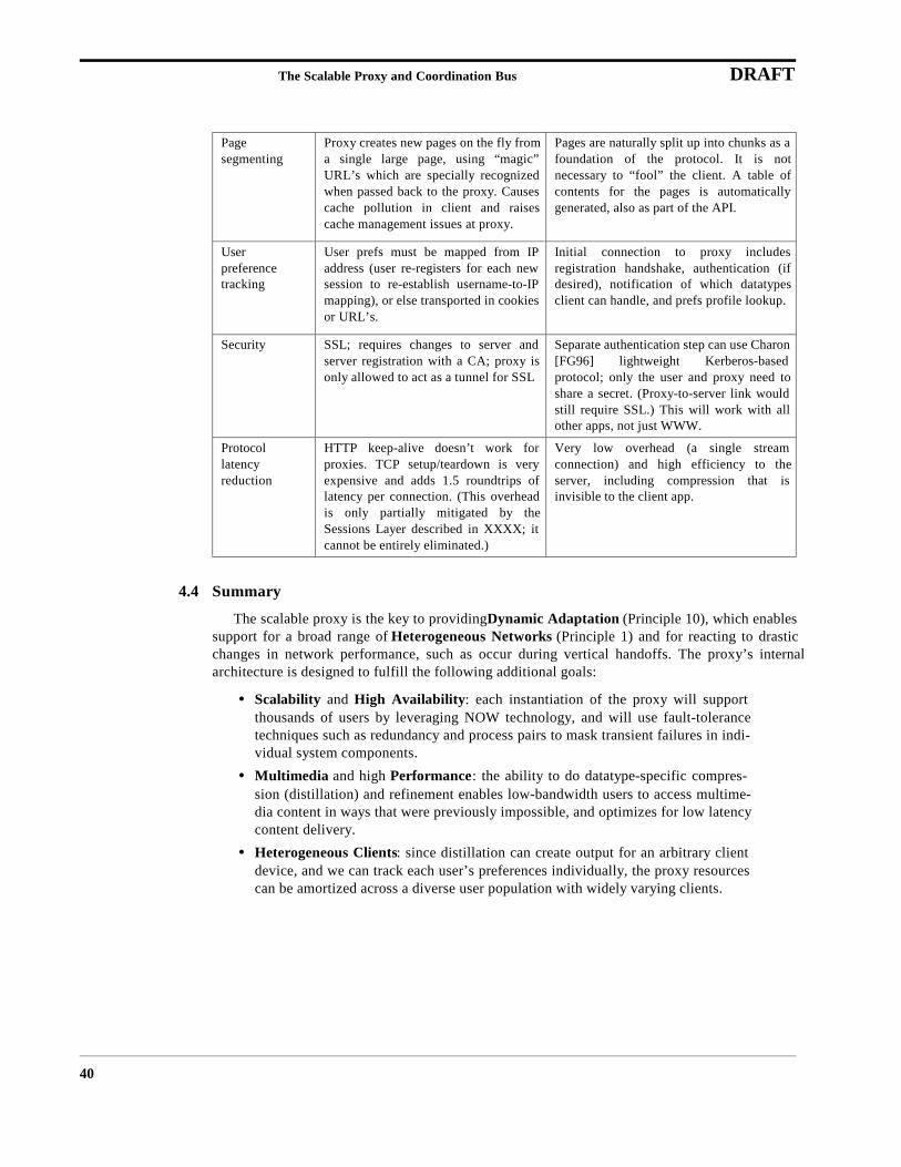
The Scalable Proxy and Coordination Bus DRAFT
40
4.4 Summary
The scalable proxy is the key to providing Dynamic Adaptation (Principle 10), which enablessupport for a broad range of Heterogeneous Networks (Principle 1) and for reacting to drasticchanges in network performance, such as occur during vertical handoffs. The proxy’s internalarchitecture is designed to fulfill the following additional goals:
• Scalability and High Availability: each instantiation of the proxy will supportthousands of users by leveraging NOW technology, and will use fault-tolerancetechniques such as redundancy and process pairs to mask transient failures in indi-vidual system components.
• Multimedia and high Performance: the ability to do datatype-specific compres-sion (distillation) and refinement enables low-bandwidth users to access multime-dia content in ways that were previously impossible, and optimizes for low latencycontent delivery.
• Heterogeneous Clients: since distillation can create output for an arbitrary clientdevice, and we can track each user’s preferences individually, the proxy resourcescan be amortized across a diverse user population with widely varying clients.
Pagesegmenting
Proxy creates new pages on the fly froma single large page, using “magic”URL’s which are specially recognizedwhen passed back to the proxy. Causescache pollution in client and raisescache management issues at proxy.
Pages are naturally split up into chunks as afoundation of the protocol. It is notnecessary to “fool” the client. A table ofcontents for the pages is automaticallygenerated, also as part of the API.
Userpreferencetracking
User prefs must be mapped from IPaddress (user re-registers for each newsession to re-establish username-to-IPmapping), or else transported in cookiesor URL’s.
Initial connection to proxy includesregistration handshake, authentication (ifdesired), notification of which datatypesclient can handle, and prefs profile lookup.
Security SSL; requires changes to server andserver registration with a CA; proxy isonly allowed to act as a tunnel for SSL
Separate authentication step can use Charon[FG96] lightweight Kerberos-basedprotocol; only the user and proxy need toshare a secret. (Proxy-to-server link wouldstill require SSL.) This will work with allother apps, not just WWW.
Protocollatencyreduction
HTTP keep-alive doesn’t work forproxies. TCP setup/teardown is veryexpensive and adds 1.5 roundtrips oflatency per connection. (This overheadis only partially mitigated by theSessions Layer described in XXXX; itcannot be entirely eliminated.)
Very low overhead (a single streamconnection) and high efficiency to theserver, including compression that isinvisible to the client app.
Network Services DRAFT
41
5 Network Services
The Network Services component of the architecture builds atop our innovations in network-layer routing and transport and our use of application-specific proxy-servers. It provides support forlocale-specific discovery of available resources (such as proxies) and “on-the-move” reconfigura-tion of and adaptation to these resources. This functionality is required to support seamless interac-tion with the environment as clients roam in autonomous (separately-administered) overlayednetworks.
Users wish to invoke services -- such as controlling the lights, printing locally, gaining access toapplication-specific proxies, or reconfiguring the location of DNS servers -- from their mobiledevices. But it is difficult to obtain wide-spread agreement on “standard” interfaces and methodsfor such service invocation. Thus, the challenge is to develop an open service architecture thatallows heterogeneous client devices to discover what they can do in a new environment while mak-ing minimal assumptions about standard interfaces and control protocols.
The basic premise in developing such a component in our architecture is that providing an “IPdial-tone” to clients isn’t enough. We must augment basic IP connectivity with an adaptive networkservices infrastructure that allow users to control and interact with their environment. Distillationproxies are one example of a network service that may require discovery and reconfiguration. Wealso must provide meta-services that allow for interactions between particular separately-discov-ered services to allow for interoperability given inevitable variability and lack of “a priori” stan-dards. The challenge is developing an open service architecture that allows heterogeneous clientdevices to discover what they can do in a new environment, and yet which makes minimal assump-tions about standard interfaces and control protocols.
In developing this architecture, we have designed, implemented, and deployed in our ComputerScience building the following example services:
• untethered interaction with lights, video and slide projectors, a VCR, an audioreceiver, an echo canceller, motorized cameras, video monitors, and A/V routingswitchers from a wirelessly connected laptop computer;
• automatic “on-the-move” reconfiguration for use of local DNS/NTP/SMTP serv-ers, HTTP proxies, and RTP/multicast gateways;
• audited local printer access;
• visualization of physical geography and discovered object locations via a protocolfor interactive floor maps; \item tracking of users and other mobile objects with“caller ID;”
• advertising available local services (or other data) to unregistered (“anonymous”)clients.
In realizing this architecture, we employ a few key techniques:
• augmenting standard mobility beacons with location information, scoping features,and announcements from a service discovery protocol;
• using interface specifications that combine an interface definition language withthe semantics of a model-based user interface; and
• hosting scripts in the infrastructure that:
• map exported object interfaces to client device control interfaces,
• compose object interactions, and

Network Services DRAFT
42
• automatically remap the destination of object invocations to changing serverlocations.
The physical components of the testbed in a local seminar room are illustrated in Figure 13. Wealso leverage facilities in a collaboration laboratory (CoLab) and a student office; all containdevices that can be accessed and/or controlled via our software.
The network services’ subcomponents are a scoped service discovery protocol and bootstrap,scoped access control and security, and facilities for passing and mapping discovered interfaces toclient devices. We start by breaking these down into a discussion of Controllable Objects, describ-ing issues in connecting devices to the network and providing them to local users; Service Adver-tisement and Discovery, describing how such objects and services need to be named and advertised;and Mapping Client Controls to Exported Objects, where we describe how to make theses interac-tions seamless. We then dive into implementation issues and details, describe the suite of examplead hoc mobile services incorporated into our testbed, and finish with discussion, related and futurework, and conclusions.
5.1 Controllable Objects
Most physical objects provide only manual controls. A controllable object, on the other hand,responds to control requests or transmits status information through an exposed interface accessibleover the network. Objects must be augmented with this ability to allow for network-based access.Issues in doing so include aggregation of objects into a controllable unit, addressability/naming,and conflict resolution.
5.1.1 Aggregation
At what granularity must controllable objects be implemented? In keeping with our goal ofadaption, we allow it to be arbitrary. Requiring fine-grained controllable objects is difficult because
FIGURE 13. Part of the project operating environment: 405 Soda Hall.
Network Services DRAFT
43
individual objects may be too numerous or the expense of individual control may be too high. Forexample, while it is possible to make every lightbulb its own controllable object, the sheer numberof them in a typical building, the expense of assigning processing to each one, the difficulty of wir-ing each to the network, etc., would mitigate such a decision. Instead, control functionality could beassigned to a bank of lights, and what is augmented is the switch bank rather than all of the individ-ual lightbulbs. In general, the granularity at which object capabilities are exported shouldn’t speci-fied by the architecture. The difficulty, then, is to allow client controls to aggregate and subsetcontrollable objects components in a manner transparent to the client interfaces to them.
We provide this feature by providing clients with a facility for hosting scripts that map exportedobject interfaces to client device control interfaces and compose object interactions. The scriptsleverage the use of interface specification languages for object description, allowing access to sub-components and composition of remote objects. This disassociates controllable object granularityfrom actual control granularity.
5.1.2 Naming
Another impact of making controllable objects accessible is that the current infrastructure fornaming must be extended to include them. These objects do not have individual IP addresses orsession descriptions, but instead are accessible through servers and, due to location-based usage,often have fine geographic scope. Users want to make queries based on geographic information(location), data type (position in class hierarchy), scope (accessibility range), and the controlauthority (the “owner” and/or position in an organization hierarchy for dealing with access-con-trol). These properties can dynamically change, and the hierarchies are not strict (i.e., there can bemultiple paths from the root). It is unclear whether these four orthogonal components need to coex-ist in the globally-visible naming scheme (augmenting or acting together as a fully-qualified uniqueobject name), or whether some can be treated as “properties” rather than elements of the name.
Existing methods for naming include using the Domain Name Service (DNS) [MD88] forobjects with unicast IP addresses or the Session Description Protocol (SDP) [HJ97] for lightweightsessions. DNS is a widely-deployed distributed name service. SDP is a container protocol for asso-ciating a single name with a collection of application-specific multimedia transports and their (mostoften multicast) channels. SDP messages are delivered via the Session Announcement Protocol(SAP) [Han97], an announce/listen protocol that uses scoped constant-bandwidth allocations.
Alternatives for the implementation of object naming include extending DNS with new recordtypes, extending SDP/SAP with new application types and finer scoping, hybridizing the two, ordeveloping a separate hierarchy to match this need rather than overloading DNS and/or SDP/SAP.Further implications of this decision are noted in Section 5.2, where we describe service announce-ment and discovery. Our current proposal for the geographic name axis is presented inSection 5.5.1, where we describe our prototype map service.
5.1.3 Shared Control Conflicts
When multiple users attempt to share a controllable object, there is the potential for conflicts inthe requests. Existing systems manage this difficulty by providing well-formed application-specificsolutions and limiting the set of conflict states. One example is the elevator. Requests to an elevatorare not commands, but are instead idempotent inputs to an algorithm that decides the order foractions to take place (if at all). Individual elevators react to input combinations differently, and thisis acceptable. We propose using such application-specific algorithms for controllable objects(encapsulated behind the remote object invocation specification). Leveraging “authentication” fea-tures such as locking (minimally coarse-grain, possibly finer) and access levels (“capabilities”) can
Network Services DRAFT
44
assist in reducing the conflict state set and is very practical; i.e., the “owner” of the device canalways override “users,” etc.
5.1.4 Cameras as Object Interfaces
Another approach for interacting with objects is to use video capture augmented with imageprocessing (“computer vision”) where applicable. Example uses of this approach include fine-grainobject tracking, directionality sensing, and event triggers keyed to particular circumstances[MF96]. For example, a camera can be used to detect the opening of a door or window. In this case,it is the camera that exports the control interface. Using cameras for such duties has extensiveimplications for security and privacy control, but is a viable alternative when direct manipulation isnot.
5.2 Service Advertisement and Discovery
The function of a service discovery protocol is to allow for the maintenance of dynamic reposi-tories of service information, advertise the availability of this information, and support attributequeries against it.
Service advertisement must scale with both the number of advertised services and to the wide-area. Even as larger numbers and classes of devices become network-accessible (e.g., “IP lightbulbs”), the bandwidth consumed by these advertisements must scale sub-linearly. Fortunately,repository information is often local in nature, and though objects can be addressed globally, it cansupport eventual consistency semantics. This allows for the use of a soft-state update approach suchas an announce/listen protocol. These announcements and queries can be scoped and this scopingcan provide hierarchy. Difficulties include that the scoping granularity may be very fine, at thelevel of individual rooms or network subnets/cells, and that scopes must dynamically adapt to sup-port incremental, independent local deployment of various services.
Our observation is that this requires a technique combining the properties of a distributed nameservice (e.g., DNS) and an announcement protocol (e.g., SAP). The latter “pushes” unknownnames/descriptions to the client to facilitate discovery, while the former allows the client to “pull”information about objects given their names. The hybrid technique is to advertise the location oflocal name services in addition to object descriptions. This allows a single message to, in effect,advertise a collection of objects, and provides advertisement hierarchy (possibly, but not necessar-ily, aligned to the naming hierarchy like DNS) with scaling sub-linear in the number of advertisedobjects.
The Service Location Protocol [VGPK97], a resource discovery protocol under development bythe IETF Service Location working group, is one proposal for implementing such a service. In SLP,query processing is performed at directory agents and distributed via multicast. Our protocol willleverage features of SLP, specifically the query grammar and message formats.
For basic operation, the only mechanism necessary is a function to allow mobiles to map namesto values. These can be obtained by querying a local server or by receiving them via multicast (ourcurrent prototype operates via the former.) We describe our own mechanisms for finding the cor-rect local server or multicast addresses and initializing the mappings. Finding one of the correctlocal servers is similar to delivering the correct scope attribute to the mobile host in SLP. (The SLPscope attribute is used to administratively aggregate an otherwise disparate set of services.)

Network Services DRAFT
45
5.3 Mapping Client Controls to Exported Objects
The network services component allows for UI widgets to remain in familiar locations and in afamiliar form even as the particular devices that the widget controls change (e.g., a light switch).We now describe our mechanisms for enabling this behavior.
5.3.1 Transduction Protocols
A transduction protocol maps a discovered object interface to one that is expected by a givenclient device. It supports interoperability by adapting the client device’s interface to match the con-trollable object’s interface. It allows for custom user interfaces to ad hoc services, such as allowinga virtual “light switch” on a control panel to always control the closest set of lights. Without a map-ping function, every change in location might require a new interface be retrieved.
An issue with transduction protocols is how to map control functions into a UI supported by theportable device. As an example, assume a client device has a two-position switch widget for usewith the local light controller. At a visited location, the light controller supports continuous dim-ming. In this case, the client may substitute a slider widget for the switch. If it cannot do this (orchooses not to), then the purpose of the transduction protocol is to map the on/off settings of the UIto one of the two extremes of the actual dimmer control.
To support interoperability, we allow services to transfer an entire GUI to the client in a lan-guage it understands, avoiding the need for transduction. (This similar to the Java applet usagemodel but with multiple language support where necessary.) Whenever possible, though, we aug-ment the GUI (or replace the GUI completely) with an interface specification (described inSection 5.4.8). Through the interface specification, the system discovers the two data types thatneed transduction. This allow the mapping function to be inferred (heuristically, from a library, orby querying the client) and then installed at the local transducing proxy that sits between the twoendpoints. The interface specification can also be used directly to generate a rough GUI when nointerface implementation appropriate for the client is available, or when only portions of the con-trollable objects’ interface is of interest of the user (i.e., to conserve screen real estate or to add abutton into a user-defined control panel).
The interface descriptions not only allow for data type transducers between client and server;they also provide the critical layer of indirection underneath the user interface. Examples includecomposing “complex” behaviors and remapping the destination of object invocations to account formobility.
5.3.2 Complex Behaviors
Objects have individualized behaviors. We wish to couple and compose these individual behav-iors to obtain more complex behaviors within the environment. For example, consider a scenariowhere music follows you as you move around a building. One behavior of the sound system is toroute music to specific speakers. A behavior of location tracking services is to identify where spe-cific objects are located. A “complex” behavior allows us to compose these more primitive behav-iors of sound routing and location tracking to obtain the desired effect of “music that follows.”
A key problem is that there is no common control interface for individual components. Further-more, some behaviors may require maintenance of state that is independent of both subcompo-nents. An example of the latter is instructing the coffee maker to brew only the first time eachmorning that the office door opens. Another issue is a policy-level difficulty implied by this sce-nario: resolution of incompatible behaviors. If another user considers music to be noise, the visitinguser’s music may or may not be turned off in their presence, depending on seniority, social conven-tion, explicit heuristics, or otherwise. At a minimum, the system must guarantee that it will detect
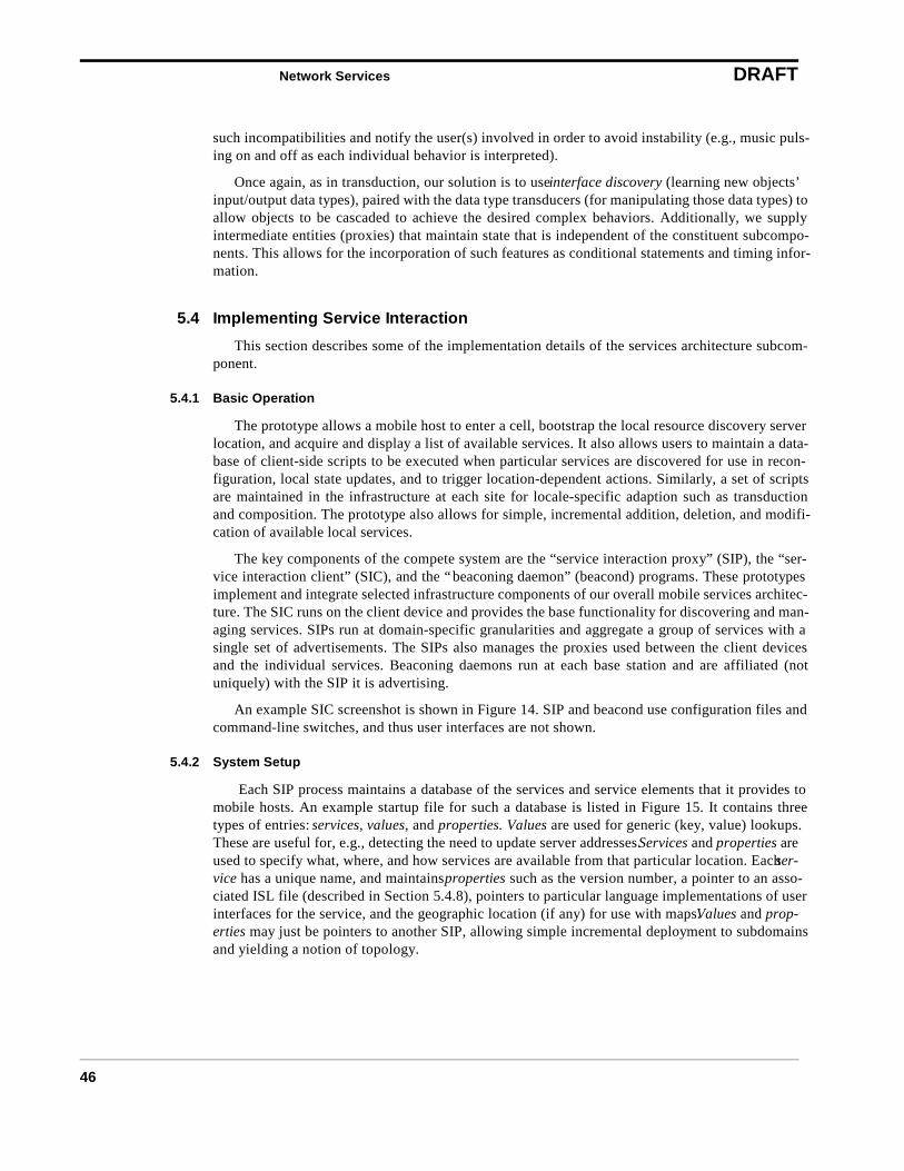
Network Services DRAFT
46
such incompatibilities and notify the user(s) involved in order to avoid instability (e.g., music puls-ing on and off as each individual behavior is interpreted).
Once again, as in transduction, our solution is to use interface discovery (learning new objects’input/output data types), paired with the data type transducers (for manipulating those data types) toallow objects to be cascaded to achieve the desired complex behaviors. Additionally, we supplyintermediate entities (proxies) that maintain state that is independent of the constituent subcompo-nents. This allows for the incorporation of such features as conditional statements and timing infor-mation.
5.4 Implementing Service Interaction
This section describes some of the implementation details of the services architecture subcom-ponent.
5.4.1 Basic Operation
The prototype allows a mobile host to enter a cell, bootstrap the local resource discovery serverlocation, and acquire and display a list of available services. It also allows users to maintain a data-base of client-side scripts to be executed when particular services are discovered for use in recon-figuration, local state updates, and to trigger location-dependent actions. Similarly, a set of scriptsare maintained in the infrastructure at each site for locale-specific adaption such as transductionand composition. The prototype also allows for simple, incremental addition, deletion, and modifi-cation of available local services.
The key components of the compete system are the “service interaction proxy” (SIP), the “ser-vice interaction client” (SIC), and the “beaconing daemon” (beacond) programs. These prototypesimplement and integrate selected infrastructure components of our overall mobile services architec-ture. The SIC runs on the client device and provides the base functionality for discovering and man-aging services. SIPs run at domain-specific granularities and aggregate a group of services with asingle set of advertisements. The SIPs also manages the proxies used between the client devicesand the individual services. Beaconing daemons run at each base station and are affiliated (notuniquely) with the SIP it is advertising.
An example SIC screenshot is shown in Figure 14. SIP and beacond use configuration files andcommand-line switches, and thus user interfaces are not shown.
5.4.2 System Setup
Each SIP process maintains a database of the services and service elements that it provides tomobile hosts. An example startup file for such a database is listed in Figure 15. It contains threetypes of entries: services, values, and properties. Values are used for generic (key, value) lookups.These are useful for, e.g., detecting the need to update server addresses. Services and properties areused to specify what, where, and how services are available from that particular location. Each ser-vice has a unique name, and maintains properties such as the version number, a pointer to an asso-ciated ISL file (described in Section 5.4.8), pointers to particular language implementations of userinterfaces for the service, and the geographic location (if any) for use with maps. Values and prop-erties may just be pointers to another SIP, allowing simple incremental deployment to subdomainsand yielding a notion of topology.
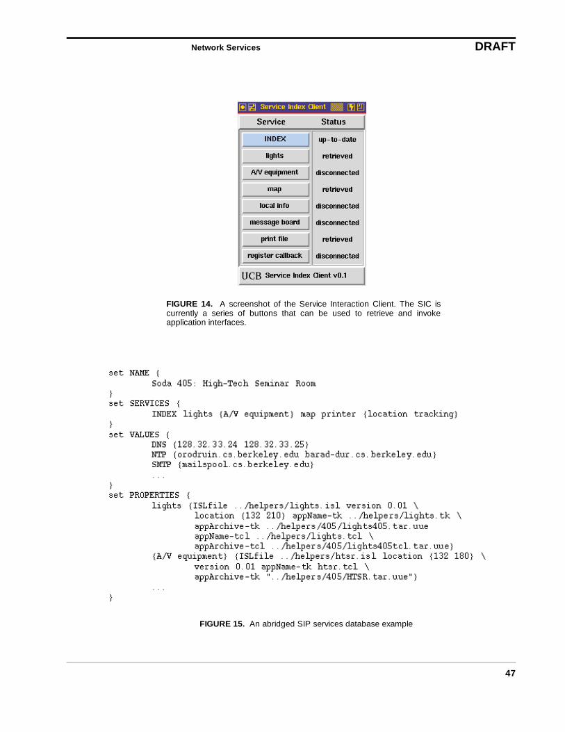
Network Services DRAFT
47
FIGURE 14. A screenshot of the Service Interaction Client. The SIC iscurrently a series of buttons that can be used to retrieve and invokeapplication interfaces.
FIGURE 15. An abridged SIP services database example
Network Services DRAFT
48
5.4.3 Message-level Detail
The client enters a cell with a beaconing daemon. The daemon sends periodic broadcasts thatcontain the bootstrap address and port number of that cell’s SIP. The client registers with the basestation to establish IP connectivity if it needs to. It then requests the well-known meta-serviceindex, which returns a list of the services available. Based on the contents of the reply, the clientrenders labelled UI buttons for unknown services, executes scripts in a database to allow for locale-specific reconfiguration, and tells the local SIP to remap the location of running services and setupany necessary widget binding remappings.
When a user wishes to use a particular service, the client software checks its local cache ofapplications. If an interface supporting the requested application is not there, it asks the SIP for theservice’s “properties.” This is a list of available interface descriptions and/or implementations. Italso receives any service metadata (such as version numbers). It then chooses either to download aparticular interface implementation (e.g., as a Java applet), the generic interface description, orboth. The SIC then unpacks the received archives, sets up transducers matching the interfacedescription to the device characteristics, and finally executes the GUI.
An example exchange of protocol messages for a client moving between SIPs is illustrated inFigure 16.
5.4.4 Client Bootstrap
For a client to use services, it must first find the address of the local resource discovery server orthe local multicast address where services are advertised. In our architecture, this bootstrap aboveIP is minimal: there is an indirection embedded in the mobility beacons. This minimal bootstrap
FIGURE 16. Protocol message timings for a client moving between SIPservers (dashed lines are beacons): (a) index #1 request/reply (b) request/reply for “lights” ISL file and interface (c) index #2 request/reply (d) “lightsdim” button press retrieves new ISL file to remap RPC, then completes.
Network Services DRAFT
49
standardizes the mechanism without constraining its interpretation, thereby allowing variation inresource discovery protocols as they evolve.
5.4.5 Beaconing
Beaconing is required in a system to facilitate notification of mobility-based changes in the rel-ative position of system components. Its use is motivated by inherent availability of physical-levelhardware broadcast in many cellular wireless networks and the need to track mobiles to provideconnectivity.
Two issues arise once the decision to beacon has been made. The first is which direction tosend them: uplink, downlink, or both. The second is what information to put on the beacons, if anyat all. (An empty beacon acts as a simple notification of the base station address, available in thepacket header.) These issues are discussed in the following subsections.
5.4.5.1 Beaconing Direction
In terms of choosing whether to have client devices or infrastructure servers beacon, existingsystems can be found which have made either choice. Client beaconing is used in both the ActiveBadge [HH94] and ParcTab systems [SAG+93], while server beaconing was used in ColumbiaMobile IP [IDM91]. IETF Mobile IP utilizes both periodic advertisements and periodic solicita-tions.
One might expect that the different policies optimize for different applications’ operatingmodes. This is indeed the case: there are trade-offs in such a decision, as it varies allowances forprivacy, anonymity, particular protocols’ performance, and scalability.
There are a number of metrics for considering qualitative trade-offs between the two decisions:
• Power: Less power is consumed at the mobile by periodically listening than byperiodically transmitting, but this difference can be mitigated by hardware/MACdesign [SGHK96].
• Detection: When base stations (BSs) beacon, mobiles need not transmit to detectwhen all contact is lost. When clients beacon, BSs need not transmit to detect usermobility.
• Multiples: With BS beaconing, detection of multiple beacons can be used to assisthandoff. With client beaconing, the number of received beacons specifies the num-ber of clients in the cell.
• Location Anonymity: When BSs beacon, anonymity is preserved for non-transmit-ting mobiles; when clients beacon, the granularity of the infrastructure is invisibleto users.
• Geographic Mapping: BS beaconing maintains a consistent mapping betweengeography and beacon broadcast cell; client beaconing maintains a mapping of cli-ents to multiple cells.
• Bandwidth Scaling: BS beaconing implies less beacon traffic per cell given a natu-ral many-to-one mapping of mobile hosts to base station cells. Conversely, clientbeaconing optimizes for very small cells. (Assuming other parameters remain con-stant.)
Our system uses base station beaconing. We believe this is the correct design choice for threekey reasons: the support for user (rather than infrastructure) anonymity, better bandwidth scalabil-ity in a network where there are many MHs per BS, and because power is more precious on mobiledevices.

Network Services DRAFT
50
5.4.5.2 Beacon Augmentation
The second question is whether to augment mobility beacons with additional data. Augmentingbeacons with application-specific data does two things. It makes data available to mobiles beforeregistration (in the Mobile IP sense), allowing the possibility of “anonymous” access to this broad-cast data (at a cost of management overhead and increased beacon size due to the piggybacking). Italso aligns the mobility beacons with a form of announce/listen protocol that has limited announce-ment timer adaptability. The announcement timer can only be set to discrete multiples of the basebeaconing rate (that rate determined as sufficient to detect handoff within some acceptable latency.)
Possible uses for such piggybacked beacon data include:
• merging of other periodic broadcasts to amortize header and MAC overhead (e.g.,NTP beacons, Mobile IP foreign agent advertisements);
• pricing information useful to the host to determine whether to register;
• commonly accessed time-variant data; \item a list of some or all of the availableservices in the cell;
• “tickets” for providing scoped access control (discussed in Section 5.4.7).
The utility of beacon payload augmentation is highly dependent on the direction of the beacon-ing, traffic patterns, and application mix. An argument against augmenting beacons at all is thatorthogonal applications shouldn’t mix their data units that may have been “properly” sized by theapplication (c.f., application-level framing [CT90] or joint source-channel coding [MVV96]).
We choose to augment our beacons with bootstrap information, a ticket for scoping of services,and a dynamically configurable application-specific payload. The encoding is shown in Figure 17.One common application-specific payload is the contents of the cells’ index, allowing anonymousassessment of available services and reducing discovery latency.
Whether merging data into beacons is a benefit depends on the metric of evaluation. We are stilltrying to quantitatively determine which data, if any, is best dedicated to these bits for optimizingreasonable client-driven workloads.
5.4.6 Charon: Proxied Secure Access
Authentication to network services is based upon the Kerberos IV [Ste88] infrastructure. Wehave engineered a partitioning of the Kerberos implementation, called Charon [FG96], for usebetween resource-poor clients (e.g., PDAs) and a proxy. This partitioning allows the proxy to inter-act with the Kerberos infrastructure on behalf of the clients, giving the clients full authenticated(and optionally encrypted) access to the services but relieving them of the burden of having a fullKerberos implementation. Because the Kerberos infrastructure itself is unmodified, all of the secu-
FIGURE 17. The service beacon encoding includes bits for theservice interaction bootstrap and location queries. Not shown are thedetails of any particular mix of application-specific payloads.
Network Services DRAFT
51
rity features of Kerberos are preserved, and resource-capable clients can make use of Kerberos asthey normally would.
Charon is our proxied implementation of Kerberos that provides indirect authentication andsecure communications with personal mobile devices. By indirect authentication, we mean thatmost of the computational resources needed to conduct the Kerberos protocol and establish a securechannel with a network service are located at a proxy, a process running on a resource-rich desktopworkstation in the well-connected infrastructure. This proxied approach simplifies the client soft-ware considerably: minimal client-side software is sufficient to preserve Kerberos semantics andsecurity guarantees, while off-loading substantial protocol processing, credentials management,and other housekeeping tasks to a proxy in which minimal trust must be placed.
Charon provides three secure-access models:
• A means of authenticating clients to a service attachment point (proxy) using aKerberos-based protocol;
• Establishment of a secure communication channel to that attachment point, onwhich future logical channels can be multiplexed, thus providing encryption to theproxy when link-level encryption is weak or unavailable;
• Both end-to-end and proxied access to two-way-authenticated Kerberized servicesin an existing Kerberos infrastructure.
Only DES encryption and decryption need be ported to clients; in our environment these clientsmay suffer from limited resources and dissimilar development environments, both of which wouldmake a full port of the Kerberos implementation exceedingly difficult. Furthermore, rather thanunderstanding multiple message formats and communicating with multiple Kerberos entities, theclient needs to understand only a single message format and communicates exclusively with a sin-gle entity (the Charon proxy), which can also serve as a network gateway if necessary.
Neither the user’s Kerberos password nor the key required to construct Kerberos authenticators(used when requesting access to new services) ever leave the client. Charon has the same immunityto protocol-based attacks as Kerberos does, and is more immune to certain end-to-end attacksbecause of the nature of the devices on which it is designed to run, providing an alternate means ofKerberos authentication for security-conscious users.
5.4.7 Scoped Access Control
Making services available to visitors brings up a host of general security issues, including thosespecific to the wireless domain [Bro95,AD94]. In addition to standard cryptography-based securitywith passwords, capabilities (e.g., Kerberos), and public-key encryption, service interaction sys-tems specifically require additional access control. This is due to our extending devices to be net-work-addressable entities. In general, global access control is necessary, but not sufficient; theexpected behavior that environmental changes can only be affected by people in that environment(e.g., lights cannot be turned off by a person across the country) has been broken. Maintaining thisnorm is important when extending existing human social metaphors into an environment with con-trollable objects. We address this by embedding tickets, random fixed-length bit vectors, in themobility beacons and requiring the current ticket to be included in all communications to servers.Periodically changing the tickets in an unpredictable way (truly randomly) and scoping the broad-cast (implicitly via the cellular wireless network broadcast cell or explicitly with the IP multicastTTL field) prevents remote access from nodes even on the access control list that aren’t local. Thispairs the geographic scoping of the environmental controls (what we cannot control) to the topolog-ical scope (what we can control). This ticket-based exclusion can be overridden (by separately mul-
Network Services DRAFT
52
ticasting or unicasting the ticket when necessary), but by making the default access restricted, webetter emulate the existing paradigm.
5.4.8 Client Interfaces
5.4.8.1 Motivating Interface Specifications
Clients can be computationally impoverished, have variations in display (color depth, resolu-tion, screen size), support different interface paradigms (keyboard, pen, touch), and are often inter-changeable with one another (and therefore not preconfigured).
Due to the need to support such end devices, especially extremely resource-poor PDAs, ourarchitecture focuses on providing thin client interfaces and offloading processing to proxies. Rec-ognizing that expecting custom UIs to be available for all services on all different types of hard-ware isn’t realistic, we propose exposing controllable objects through an interface specificationlanguage (ISL). The ISL is used in addition to other reference language implementations of aninterface, thus allowing for compatible but independent coexisting interfaces. It exposes the syntaxof each services’ control interface. Upon discovery of a service, the client device checks to see if alanguage implementation is available that it can support, and if not, uses the ISL file to learn theRPC calls and parameters that can be used to access the service. It additionally allows the device toadapt the representation to a format appropriate for the device’s characteristics, and allows the userto place the elements manually and independent of one another for fine-grain control. Automaticlayout heuristics can also be used.
5.4.8.2 Interface Specification
The conventional notion of an Interface Definition Language (IDL) (e.g., the CORBA IDL) isto specify parameters, parameter data types, and parameter-passing conventions for remote objectinvocation [Cor97]. The basic function of a Model-based User Interface [SFG93] is to specifyinterfaces as structured widget hierarchies along with sets of constraints. The actual interface isderived from the model at run time or through a compilation step. This allows interfaces to main-tain a consistent look-and-feel even as elements are added and deleted. Our goal is to unify theseapproaches, allowing remote object APIs to be augmented with UI models. This hybrid wouldallow both composition of the object invocations (RPCs), and separate subsetting/aggregation ofobject UI elements. We call this combination an interface specification, and its grammar an Inter-face Specification Language, or ISL.
As a concrete example, we would like to allow an application to buffer DNS queries (calls toone object method) through a local cache (calls to another object), while instantiating the new func-tionality either through the original UI or via a new one.
An important design criteria is to make the hybrid robust enough to be applicable to a variety ofclasses of client devices (each with their own implicit assumptions about widget implementation),yet simple enough to be manageable.
The use of an ISL requires services to explicitly support a layer of indirection through the ser-vice discovery mechanism, allowing transparent remapping of individual interface elements. Thisindirection is critical for allowing services to be composed. As an example, the RPC command tospawn an audio conference can be rerouted to a client script that first reduces the volume of theroom’s music player and then passes along the original RPC.
Our current implementation has interfaces manually implemented in Tcl/Tk and Visual Basic.Currently, ISL uses an ad hoc grammar tuned to Tk. A related developing protocol with very simi-lar needs is the Universal Remote Console Communication Protocol (http://trace.wisc.edu/world/urcc), motivated by research in supporting interfaces for disabled users.
Network Services DRAFT
53
5.4.8.3 Prefetching
As an optimization, clients can prefetch the ISL files for active services. We illustrate with aconcrete example from our prototype. As the user moves between rooms, the light controller appli-cation UI remains the same. When the user changes the lighting in a new cell, the client applicationsends the new SIP a request for the lights ISL file, enabling the RPC command invoked by theexisting interface to be remapping so that the recipient will be the new server. This late-binding isused to conserve bandwidth on the wireless link; the total number of ISL files may be large and theclient may use one only infrequently.
The problem with late-binding is that this entire operation latency seen by the end user; in prac-tice it can be perceived as a possible error condition. (The button “doesn’t work” for a number ofseconds after it is invoked, and for this period it should probably be greyed out in the UI.)
This delay can be minimized by transparently remapping the interface elements to the newserver as soon as possible. To do so, we add one bit of per-service state, “active vs. inactive.” Thisflag is set to “active” whenever there is an RPC call from that service, and reset to “inactive” by atimeout. Upon receipt of any beacons with a new SIP, services with the “active” bit set (and avail-able in the new location) have their new ISL files prefetched automatically. (In our current imple-mentation, the index meta-service is always prefetched.) Delays can be further minimized throughmobility prediction [LM96], allowing prefetching in response to assumptions about user mobilitypatterns.
Prefetching is important in this domain because the delay experienced by an end user using ahigh-latency, low bandwidth wireless interface can be substantially less with prefetching and trans-parent remapping than with demand-paging.
5.4.8.4 Client-side Security
As for mobile code security, by transferring only an interface to the client, it is probable that asandboxed environment (such as Java, Safe-Tcl, or Janus [GWTB96]) can be used without con-straining the service’s functionality. This is another benefit of the proxy-based access model: it seg-ments the security domain and thereby allows potential internal holes to be screened from the user.This is quite similar in principle to Java’s restricting applet communication to the applet provider.
5.4.9 Naming Scheme
We express controllable object names as a globally-unique fully-qualified object name(“FQON”) and a tuple of properties. Some properties are required while others are optional butstandard. (Service-specific properties are also allowed, of course.) The set of required propertiesincludes:
• geographic location as a name hierarchy of maps that contain the object
• the data type of the object as a class in a class hierarchy and a version number
• the name of the “owner” of the object to indicate where and how to obtain authen-ticated credentials (if necessary)
• a pointer to the controlling server process (machine/port)
A common but optional property is a set of pointers to “peer” controllable objects and tags thatnote the I/O data flow that makes them peers. These are useful for specifying, for example, that the(analog) input source to a television monitor is a particular A/V switcher.
We not as of yet incorporated scope information into the object properties, but like the rest ofour proposed naming scheme, this remains as critical area for future research.
Network Services DRAFT
54
5.5 Prototype Mobile Services
In addition to the prototype service discovery and interaction implementation, we have devel-oped a number of services using the framework. These include maps that specify discoveredobjects’ positions, autoconfiguration, location tracking with privacy allowances, audited printeraccess, and interfaces to audio/visual equipment. We now describe each in turn.
5.5.1 Maps
Given a widely distributed service interaction system supporting very fine-grained services,management of even the subset of information available to the client becomes non-trivial.
We have experimented with using maps for explicit management of these services at multiplelocations. Map content is separated into three domains: network connectivity (topology and linkcharacteristics), physical geography (object locations and floorplans), and administrative domain(access rights, pricing, hierarchy).
Our prototype, of which an example view is shown in Figure 18, focuses on physical geogra-phy: allowing objects to note their location on multiple overlapping maps and receive requestspassed through the map interface (via a button press on the service indicator on the map).
The map protocol itself is a prototype based on using absolute positioning. It is designed toallow objects to position themselves without knowing exactly which map(s) the user is using. It isdesigned to allow maps to maintain hierarchical (“containment”) relationships in a distributed,extensible manner through the absolute positioning information. Represented objects must be sizedin accordance with the scale of the map(s) they are located on.
Currently, the map protocol hierarchy is defined to mirror the service interaction proxy hierar-chy: each SIP contains a single pointer to a local map. The map hierarchy thereby maintains thesame characteristics as the SIP hierarchy: it is can be arbitrarily nested and extended to subdomainswithout affecting other maps or requiring objects to relocate themselves.
Each SIP database contains pointers to local maps (and potentially different encodings of thesame map) and to map metadata including the positioning information (latitude/longitude coordi-nates of two corners) and peers. This technique extends the technique used for notation of physicalgeography in proposed “LOC” DNS record type [DVGD96] to objects without IP addresses.

Network Services DRAFT
55
5.5.2 Proxy and Gateway Autoconfiguration
Proxy and gateway autoconfiguration is a lightweight service built atop the server reconfigura-tion service. The difference between it and server reconfiguration is simply that proxies and gate-ways run in the infrastructure, between client and server. Thus, the infrastructure needs to explicitlysupport spawning of these entities. Examples of such useful intermediate agents include web prox-ies that perform on-demand dynamic transcoding [FBGA96], network data caches, real-time mediatranscoders [AMZ95], and multicast-to-unicast gateways for multicast-unaware client devices (i.e.,most PDAs).
Proxy, gateway, and server autoconfiguration is important in a mobile environment for morethan just efficiency. Using the “best current practice” technique of hard-coding DNS servers eitheras /etc/resolv.conf entries or in the Windows registry, if a user were to move from a location behinda firewall to one that is not, all lookups will fail until an out-of-band technique is used to find a newserver and the entry is manually updated. The Network Time Protocol is dependent on server loca-tion due to its use of RTT estimation, and is therefore especially suitable for use with automaticreconfiguration. A failure to keep accurate time can break some security systems, notably Ker-beros. Spawning a local RTP gateway/transcoder for unlayered data in MBone sessions may benecessary if movement has changed the bottleneck link to a source or to facilitate local manage-ment of inter-session bandwidth sharing [AMK97].
Autoconfiguration also adds a level of fault tolerance. If a network link goes down, SIP beaconscoming across the failed link will stop. The client will wait for other beacons to be obtained (c.f.,overlay networking vertical handoff), and reconfiguration to the new servers will happen transpar-ently.
FIGURE 18. Map with discovered object locations,configured for a user in the RF cell including room 405.Clicking on entries spawns the interface to that entity.
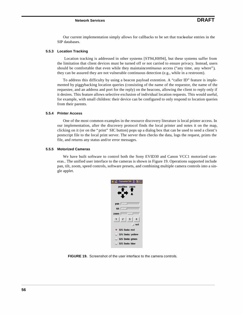
Network Services DRAFT
56
Our current implementation simply allows for callbacks to be set that track value entries in theSIP databases.
5.5.3 Location Tracking
Location tracking is addressed in other systems [ST94,HH94], but these systems suffer fromthe limitation that client devices must be turned off or not carried to ensure privacy. Instead, usersshould be comfortable that even while they maintain continuous access (“any time, any where”),they can be assured they are not vulnerable continuous detection (e.g., while in a restroom).
To address this difficulty by using a beacon payload extention. A “caller ID” feature is imple-mented by piggybacking location queries (consisting of the name of the requestor, the name of therequestee, and an address and port for the reply) on the beacons, allowing the client to reply only ifit desires. This feature allows selective exclusion of individual location requests. This would useful,for example, with small children: their device can be configured to only respond to location queriesfrom their parents.
5.5.4 Printer Access
One of the most common examples in the resource discovery literature is local printer access. Inour implementation, after the discovery protocol finds the local printer and notes it on the map,clicking on it (or on the “print” SIC button) pops up a dialog box that can be used to send a client’spostscript file to the local print server. The server then checks the data, logs the request, prints thefile, and returns any status and/or error messages.
5.5.5 Motorized Cameras
We have built software to control both the Sony EVID30 and Canon VCC1 motorized cam-eras.. The unified user interface to the cameras is shown in Figure 19. Operations supported includepan, tilt, zoom, speed controls, software presets, and combining multiple camera controls into a sin-gle applet.
FIGURE 19. Screenshot of the user interface to the camera controls.
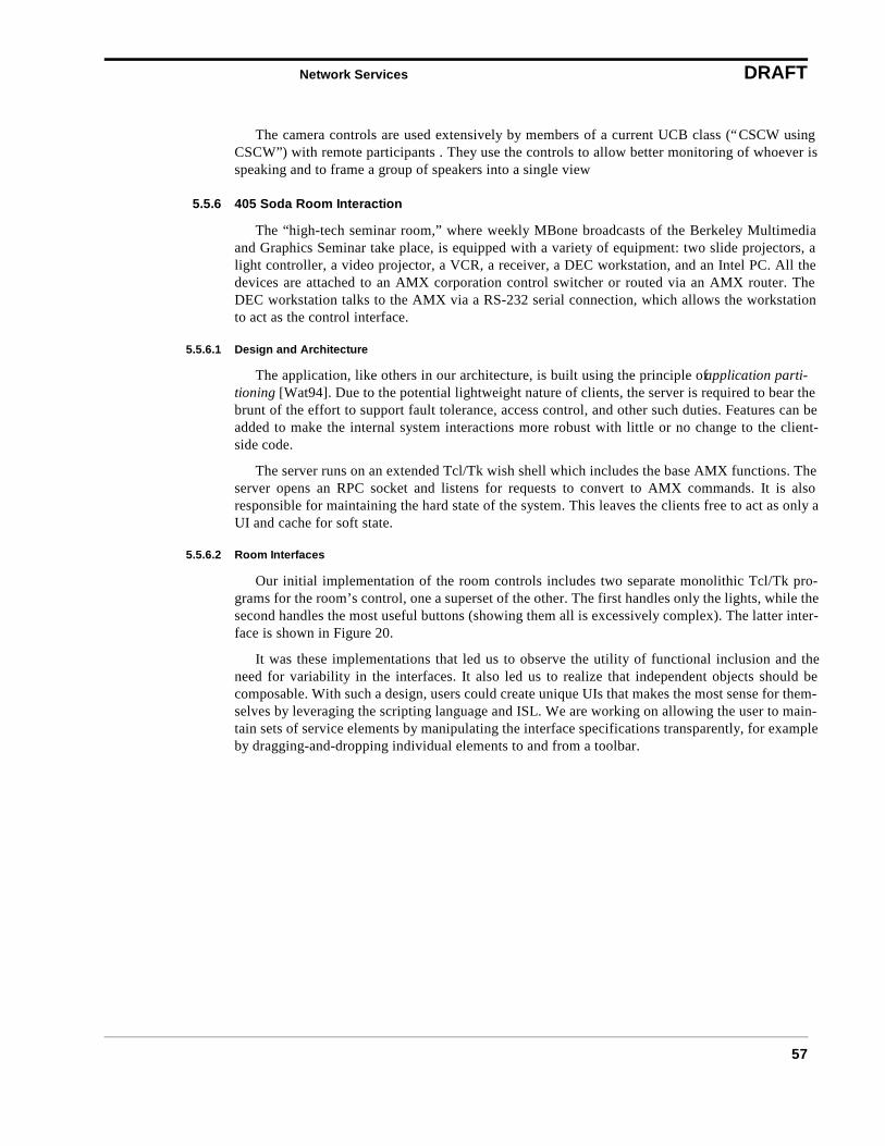
Network Services DRAFT
57
The camera controls are used extensively by members of a current UCB class (“CSCW usingCSCW”) with remote participants . They use the controls to allow better monitoring of whoever isspeaking and to frame a group of speakers into a single view
5.5.6 405 Soda Room Interaction
The “high-tech seminar room,” where weekly MBone broadcasts of the Berkeley Multimediaand Graphics Seminar take place, is equipped with a variety of equipment: two slide projectors, alight controller, a video projector, a VCR, a receiver, a DEC workstation, and an Intel PC. All thedevices are attached to an AMX corporation control switcher or routed via an AMX router. TheDEC workstation talks to the AMX via a RS-232 serial connection, which allows the workstationto act as the control interface.
5.5.6.1 Design and Architecture
The application, like others in our architecture, is built using the principle of application parti-tioning [Wat94]. Due to the potential lightweight nature of clients, the server is required to bear thebrunt of the effort to support fault tolerance, access control, and other such duties. Features can beadded to make the internal system interactions more robust with little or no change to the client-side code.
The server runs on an extended Tcl/Tk wish shell which includes the base AMX functions. Theserver opens an RPC socket and listens for requests to convert to AMX commands. It is alsoresponsible for maintaining the hard state of the system. This leaves the clients free to act as only aUI and cache for soft state.
5.5.6.2 Room Interfaces
Our initial implementation of the room controls includes two separate monolithic Tcl/Tk pro-grams for the room’s control, one a superset of the other. The first handles only the lights, while thesecond handles the most useful buttons (showing them all is excessively complex). The latter inter-face is shown in Figure 20.
It was these implementations that led us to observe the utility of functional inclusion and theneed for variability in the interfaces. It also led us to realize that independent objects should becomposable. With such a design, users could create unique UIs that makes the most sense for them-selves by leveraging the scripting language and ISL. We are working on allowing the user to main-tain sets of service elements by manipulating the interface specifications transparently, for exampleby dragging-and-dropping individual elements to and from a toolbar.
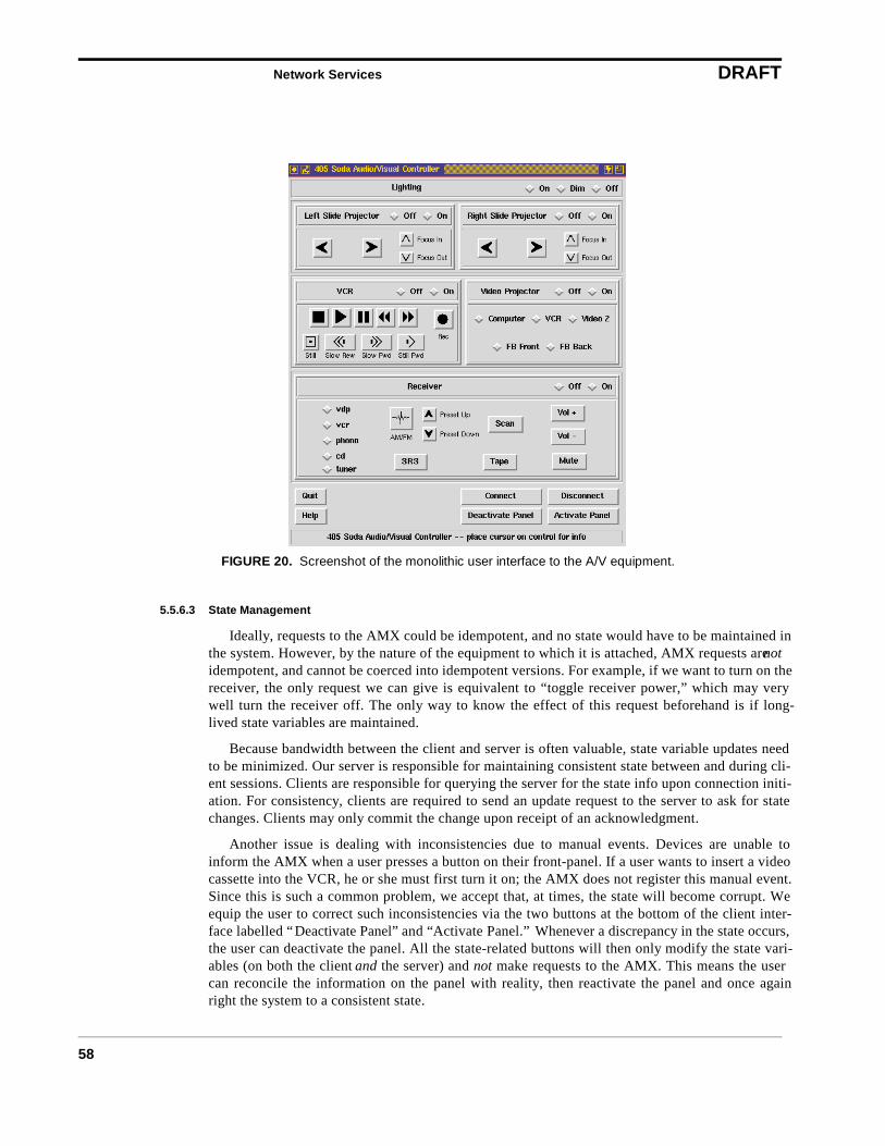
Network Services DRAFT
58
5.5.6.3 State Management
Ideally, requests to the AMX could be idempotent, and no state would have to be maintained inthe system. However, by the nature of the equipment to which it is attached, AMX requests are notidempotent, and cannot be coerced into idempotent versions. For example, if we want to turn on thereceiver, the only request we can give is equivalent to “toggle receiver power,” which may verywell turn the receiver off. The only way to know the effect of this request beforehand is if long-lived state variables are maintained.
Because bandwidth between the client and server is often valuable, state variable updates needto be minimized. Our server is responsible for maintaining consistent state between and during cli-ent sessions. Clients are responsible for querying the server for the state info upon connection initi-ation. For consistency, clients are required to send an update request to the server to ask for statechanges. Clients may only commit the change upon receipt of an acknowledgment.
Another issue is dealing with inconsistencies due to manual events. Devices are unable toinform the AMX when a user presses a button on their front-panel. If a user wants to insert a videocassette into the VCR, he or she must first turn it on; the AMX does not register this manual event.Since this is such a common problem, we accept that, at times, the state will become corrupt. Weequip the user to correct such inconsistencies via the two buttons at the bottom of the client inter-face labelled “Deactivate Panel” and “Activate Panel.” Whenever a discrepancy in the state occurs,the user can deactivate the panel. All the state-related buttons will then only modify the state vari-ables (on both the client and the server) and not make requests to the AMX. This means the usercan reconcile the information on the panel with reality, then reactivate the panel and once againright the system to a consistent state.
FIGURE 20. Screenshot of the monolithic user interface to the A/V equipment.

Network Services DRAFT
59
5.5.7 326 Soda Room Interaction
The “MASH Collaboration Laboratory,” or CoLab, is a fully outfitted room designed for exten-sive use with collaborative multicast applications. The room’s equipment includes a Xerox LiveB-orard, four television monitors, four motorized cameras, an A/V routing switcher, an echocanceller, four PCs with output scan-converted and fed into the switcher, a VCR, an audio receiver,an infrared repeater for mimicking remote control button presses, and controllable power switchesconnected to a lamp and “ON AIR” sign. Weekly broadcasts of a Fall 1997 UCB course entitled“Computer-supported Cooperative Work Using Computer-supported Cooperative Work” aresourced from here, and remote participant feeds are sent to the rooms’ four monitors and audioreceiver.
Though the equipment is different from that AMX-based system in 405 Soda, many of the capa-bilities and issues raised are similar and we will not repeat the discussion here. Only a subset of theroom’s media stream control functionality has been integrated into our architecture (camera con-trols and A/V switching).
5.6 Discussion
A layered view of our architecture is presented in Figure 21. This representation exposes howthe various mechanisms described in this paper interrelate. It also illustrates how alternative mech-anisms could replace the particular ones we have chosen without affecting the overall service archi-tecture. For example, if some to-be-determined Service Location Protocol scope deliverymechanism were to replace our augmented beaconing mechanisms for location management, theinterface discovery and data type transduction could remain unaffected.
The lowest layer is the Announcement layer. It lies directly above the network and transport lay-ers and implements the basic service bootstrap mechanisms. This includes the embedding of localserver information in the beacon payload, the ability to implement scoping mechanisms through theindirection gained by the beacons, and the possibility for additional application-specific payloadaugmentation as a performance enhancement. Its most basic function is to find servers and users.
The Query layer uses server location information from the announcement layer. It adds the abil-ity to interact with found entities such as resource servers and service interaction proxies, and pro-vides a structure for attribute queries (e.g., requests for a device-specific service applet interface).Its most basic function is to allow entities to talk to other entities.
The Interface Description layer is built on whatever query protocol is exposed by the query pro-tocol layer. It defines the set of possible interface descriptions and their semantics. Its most basicfunctionality is to map between the client device interface and the interface advertised by discov-ered objects.
The highest layer is the Application layer. It uses the interface description language exposed bythe interface description layer. It encapsulates application-specific state or data not captured by thelower layers. Examples include attaching semantic meaning to particular names (i.e., “camera”)and defining relationships between data values (i.e., the map protocol hierarchy).
Network Services DRAFT
60
5.7 Related Work
The Rover [JDT+95] and Wit [Wat94] systems also recognized the need to split applicationsinto a lightweight front-end and more heavyweight proxy at the last hop wireless link. Rover allowsthe pieces that comprise the partitioned whole to migrate between these two points, but the imple-mented prototype applications generally only exploit this for moving application data units such asmail messages, news articles, web pages, or calendar entries.
The Service Location Protocol (SLP) [VGPK97] is an example resource discovery and serviceregistration mechanism that can also function as a fine-grained name service. We are interested inmoving our resource discovery mechanism over to this evolving Internet standard. Open issuesinclude its undefined “local” scope designation and lack of an explicit scope hierarchy and peeringequivalent to our use of pointers in a service database. Our mechanism for dynamically updatingthe current SIP location could be adapted as a scope discovery mechanism and coexist with othersuch mechanisms in the proposal (i.e. having a scope DHCP option).
The seminal ParcTab [SAG+93] and Active Badge [HH94] systems, along with related workby Schilit [SAW94,ST94,Sch95], were among the first to attack the issues of client applications
FIGURE 21. A layered view of the mobile services architecture.
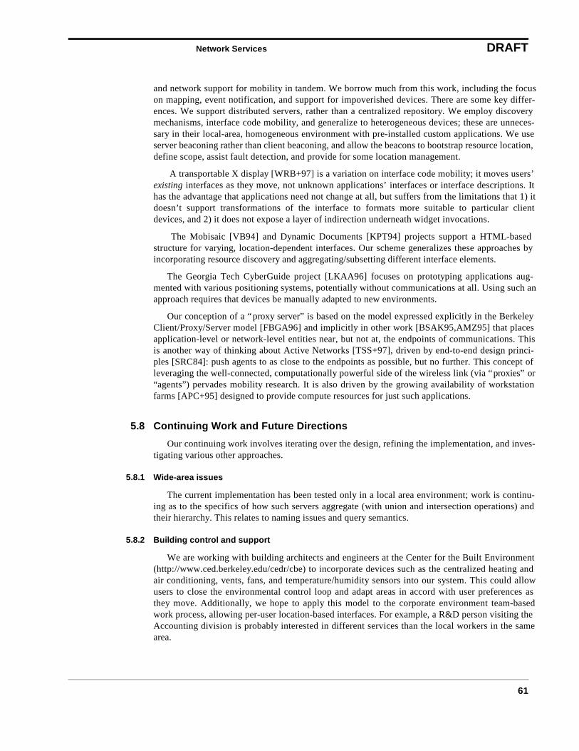
Network Services DRAFT
61
and network support for mobility in tandem. We borrow much from this work, including the focuson mapping, event notification, and support for impoverished devices. There are some key differ-ences. We support distributed servers, rather than a centralized repository. We employ discoverymechanisms, interface code mobility, and generalize to heterogeneous devices; these are unneces-sary in their local-area, homogeneous environment with pre-installed custom applications. We useserver beaconing rather than client beaconing, and allow the beacons to bootstrap resource location,define scope, assist fault detection, and provide for some location management.
A transportable X display [WRB+97] is a variation on interface code mobility; it moves users’existing interfaces as they move, not unknown applications’ interfaces or interface descriptions. Ithas the advantage that applications need not change at all, but suffers from the limitations that 1) itdoesn’t support transformations of the interface to formats more suitable to particular clientdevices, and 2) it does not expose a layer of indirection underneath widget invocations.
The Mobisaic [VB94] and Dynamic Documents [KPT94] projects support a HTML-basedstructure for varying, location-dependent interfaces. Our scheme generalizes these approaches byincorporating resource discovery and aggregating/subsetting different interface elements.
The Georgia Tech CyberGuide project [LKAA96] focuses on prototyping applications aug-mented with various positioning systems, potentially without communications at all. Using such anapproach requires that devices be manually adapted to new environments.
Our conception of a “proxy server” is based on the model expressed explicitly in the BerkeleyClient/Proxy/Server model [FBGA96] and implicitly in other work [BSAK95,AMZ95] that placesapplication-level or network-level entities near, but not at, the endpoints of communications. Thisis another way of thinking about Active Networks [TSS+97], driven by end-to-end design princi-ples [SRC84]: push agents to as close to the endpoints as possible, but no further. This concept ofleveraging the well-connected, computationally powerful side of the wireless link (via “proxies” or“agents”) pervades mobility research. It is also driven by the growing availability of workstationfarms [APC+95] designed to provide compute resources for just such applications.
5.8 Continuing Work and Future Directions
Our continuing work involves iterating over the design, refining the implementation, and inves-tigating various other approaches.
5.8.1 Wide-area issues
The current implementation has been tested only in a local area environment; work is continu-ing as to the specifics of how such servers aggregate (with union and intersection operations) andtheir hierarchy. This relates to naming issues and query semantics.
5.8.2 Building control and support
We are working with building architects and engineers at the Center for the Built Environment(http://www.ced.berkeley.edu/cedr/cbe) to incorporate devices such as the centralized heating andair conditioning, vents, fans, and temperature/humidity sensors into our system. This could allowusers to close the environmental control loop and adapt areas in accord with user preferences asthey move. Additionally, we hope to apply this model to the corporate environment team-basedwork process, allowing per-user location-based interfaces. For example, a R&D person visiting theAccounting division is probably interested in different services than the local workers in the samearea.
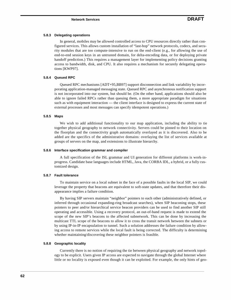
Network Services DRAFT
62
5.8.3 Delegating operations
In general, mobiles may be allowed controlled access to CPU resources directly rather than con-figured services. This allows custom installation of “last-hop” network protocols, codecs, and secu-rity modules that are too compute-intensive to run on the end-client (e.g., for allowing the use ofend-to-end session keys in an untrusted domain, for delta-encoding data, or for deploying privatehandoff prediction.) This requires a management layer for implementing policy decisions grantingaccess to bandwidth, disk, and CPU. It also requires a mechanism for securely delegating opera-tions [KWP97].
5.8.4 Queued RPC
Queued RPC mechanisms [ADT+95,BB97] support disconnection and link variability by incor-porating application-managed messaging state. Queued RPC and asynchronous notification supportis not incorporated into our system, but should be. (On the other hand, applications should also beable to ignore failed RPCs rather than queuing them, a more appropriate paradigm for situationssuch as with equipment interaction --- the client interface is designed to express the current state ofexternal processes and most messages can specify idempotent operations.)
5.8.5 Maps
We wish to add additional functionality to our map application, including the ability to tietogether physical geography to network connectivity. Servers could be pinned to their location onthe floorplan and the connectivity graph automatically overlayed as it is discovered. Also to beadded are the specifics of the administrative domains: overlaying the list of services available atgroups of servers on the map, and extensions to illustrate hierarchy.
5.8.6 Interface specification grammar and compiler
A full specification of the ISL grammar and UI generation for different platforms is work-in-progress. Candidate base languages include HTML, Java, the CORBA IDL, a hybrid, or a fully cus-tomized design.
5.8.7 Fault tolerance
To maintain service on a local subnet in the face of a possible faults in the local SIP, we couldleverage the property that beacons are equivalent to soft-state updates, and that therefore their dis-appearance implies a failure condition.
By having SIP servers maintain “neighbor” pointers to each other (administratively defined, orinferred through occasional expanding-ring broadcast searches), when SIP beaconing stops, thesepointers to peer and/or hierarchical service beacon providers can be used to find another SIP stilloperating and accessible. Using a recovery protocol, an out-of-band request is made to extend thescope of the new SIP’s beacons to the affected subnetwork. This can be done by increasing themulticast TTL scope of the beacons to allow it to cross the transit network between the subnets orby using IP-in-IP encapsulation to tunnel. Such a solution addresses the failure condition by allow-ing access to remote services while the local fault is being corrected. The difficulty is determiningwhether maintaining/discovering these neighbor pointers is feasible.
5.8.8 Geographic locality
Currently there is no notion of requiring the tie between physical geography and network topol-ogy to be explicit. Users given IP access are expected to navigate through the global Internet wherelittle or no locality is exposed even though it can be exploited. For example, the only hints of geo-
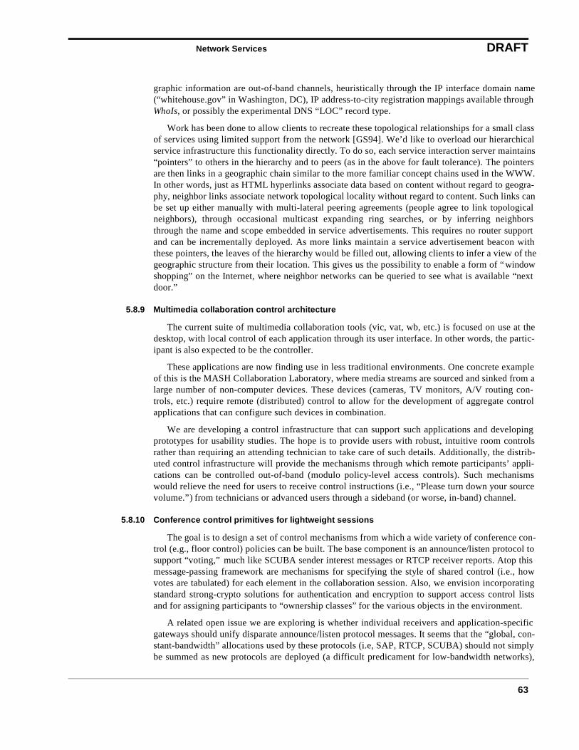
Network Services DRAFT
63
graphic information are out-of-band channels, heuristically through the IP interface domain name(“whitehouse.gov” in Washington, DC), IP address-to-city registration mappings available throughWhoIs, or possibly the experimental DNS “LOC” record type.
Work has been done to allow clients to recreate these topological relationships for a small classof services using limited support from the network [GS94]. We’d like to overload our hierarchicalservice infrastructure this functionality directly. To do so, each service interaction server maintains“pointers” to others in the hierarchy and to peers (as in the above for fault tolerance). The pointersare then links in a geographic chain similar to the more familiar concept chains used in the WWW.In other words, just as HTML hyperlinks associate data based on content without regard to geogra-phy, neighbor links associate network topological locality without regard to content. Such links canbe set up either manually with multi-lateral peering agreements (people agree to link topologicalneighbors), through occasional multicast expanding ring searches, or by inferring neighborsthrough the name and scope embedded in service advertisements. This requires no router supportand can be incrementally deployed. As more links maintain a service advertisement beacon withthese pointers, the leaves of the hierarchy would be filled out, allowing clients to infer a view of thegeographic structure from their location. This gives us the possibility to enable a form of “windowshopping” on the Internet, where neighbor networks can be queried to see what is available “nextdoor.”
5.8.9 Multimedia collaboration control architecture
The current suite of multimedia collaboration tools (vic, vat, wb, etc.) is focused on use at thedesktop, with local control of each application through its user interface. In other words, the partic-ipant is also expected to be the controller.
These applications are now finding use in less traditional environments. One concrete exampleof this is the MASH Collaboration Laboratory, where media streams are sourced and sinked from alarge number of non-computer devices. These devices (cameras, TV monitors, A/V routing con-trols, etc.) require remote (distributed) control to allow for the development of aggregate controlapplications that can configure such devices in combination.
We are developing a control infrastructure that can support such applications and developingprototypes for usability studies. The hope is to provide users with robust, intuitive room controlsrather than requiring an attending technician to take care of such details. Additionally, the distrib-uted control infrastructure will provide the mechanisms through which remote participants’ appli-cations can be controlled out-of-band (modulo policy-level access controls). Such mechanismswould relieve the need for users to receive control instructions (i.e., “Please turn down your sourcevolume.”) from technicians or advanced users through a sideband (or worse, in-band) channel.
5.8.10 Conference control primitives for lightweight sessions
The goal is to design a set of control mechanisms from which a wide variety of conference con-trol (e.g., floor control) policies can be built. The base component is an announce/listen protocol tosupport “voting,” much like SCUBA sender interest messages or RTCP receiver reports. Atop thismessage-passing framework are mechanisms for specifying the style of shared control (i.e., howvotes are tabulated) for each element in the collaboration session. Also, we envision incorporatingstandard strong-crypto solutions for authentication and encryption to support access control listsand for assigning participants to “ownership classes” for the various objects in the environment.
A related open issue we are exploring is whether individual receivers and application-specificgateways should unify disparate announce/listen protocol messages. It seems that the “global, con-stant-bandwidth” allocations used by these protocols (i.e, SAP, RTCP, SCUBA) should not simplybe summed as new protocols are deployed (a difficult predicament for low-bandwidth networks),
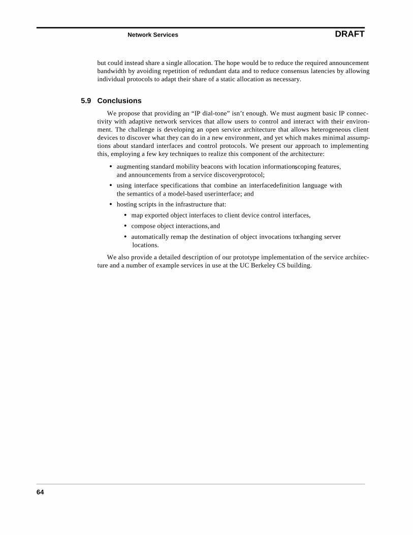
Network Services DRAFT
64
but could instead share a single allocation. The hope would be to reduce the required announcementbandwidth by avoiding repetition of redundant data and to reduce consensus latencies by allowingindividual protocols to adapt their share of a static allocation as necessary.
5.9 Conclusions
We propose that providing an “IP dial-tone” isn’t enough. We must augment basic IP connec-tivity with adaptive network services that allow users to control and interact with their environ-ment. The challenge is developing an open service architecture that allows heterogeneous clientdevices to discover what they can do in a new environment, and yet which makes minimal assump-tions about standard interfaces and control protocols. We present our approach to implementingthis, employing a few key techniques to realize this component of the architecture:
• augmenting standard mobility beacons with location information, scoping features,and announcements from a service discovery protocol;
• using interface specifications that combine an interface definition language withthe semantics of a model-based user interface; and
• hosting scripts in the infrastructure that:
• map exported object interfaces to client device control interfaces,
• compose object interactions, and
• automatically remap the destination of object invocations to changing serverlocations.
We also provide a detailed description of our prototype implementation of the service architec-ture and a number of example services in use at the UC Berkeley CS building.

The Network Stacks DRAFT
65
6 The Network Stacks
In this section, we look at how the pieces fit together from the viewpoint of the network stacks.There are three primary stacks that matter: the basestation, client, and proxy stacks. The proxyreally has two different kinds of stacks, those for clients and those for everything else such as dis-tillers or servers.
Only the client-side stack differs from standard TCP/IP. We modify or extend the network stackat every level above the physical layer. In the next three subsections, we cover the three variations:at the client, at the basestation, and at the proxy. The network stack at the (legacy) server is by def-inition an unmodified TCP/IP stack. We will start with the basestation stack since it is the simplestand then cover the client and proxy stacks. Figure 22 shows the three variations of the networkstack.
6.1 The Basestation Network Stack
There are two kinds of basestations: black-box basestations and Dædalus-aware basestations.The distinction is whether we can modify the code running on the basestation. For example, weexpect to have no influence over cellular telephone basestations, so they’re “black box”; but wehave complete control over WaveLAN basestations, so they are Dædalus-aware. It is important tosupport both kinds so that we can improve performance when we have some influence, but stillinteroperate when we have no influence.
6.1.1 Black-Box Basestations
We would still like to optimize both network and application performance to the extent possiblefor black-box basestations. In the black-box case, the basestations is essentially invisible. It takesresponsibility for routing, horizontal handoff among its the cells of its network, and whatever bea-coning is required to find client devices.
For vertical handoff, our only control over a black-box basestation is the decision whether touse it at all. In particular, we use the basestation exactly when we use that particular network. Insuch cases, the network typically assigns a particular IP address and we must use it if and only if weuse this network. Thus, vertical handoff is equivalent to switching the IP address of the client.
6.1.2 Dædalus-Aware Basestations
Given some control over the basestations, we can improve both the network performance andthe quality of vertical and horizontal handoffs.
Figure 22a shows the layers of the network stack at a Dædalus-aware basestation. Typically, thebasestation will have two physical networks: an ethernet to connect to the internet and the physicalnetwork for which it is a basestation, such as WaveLAN.
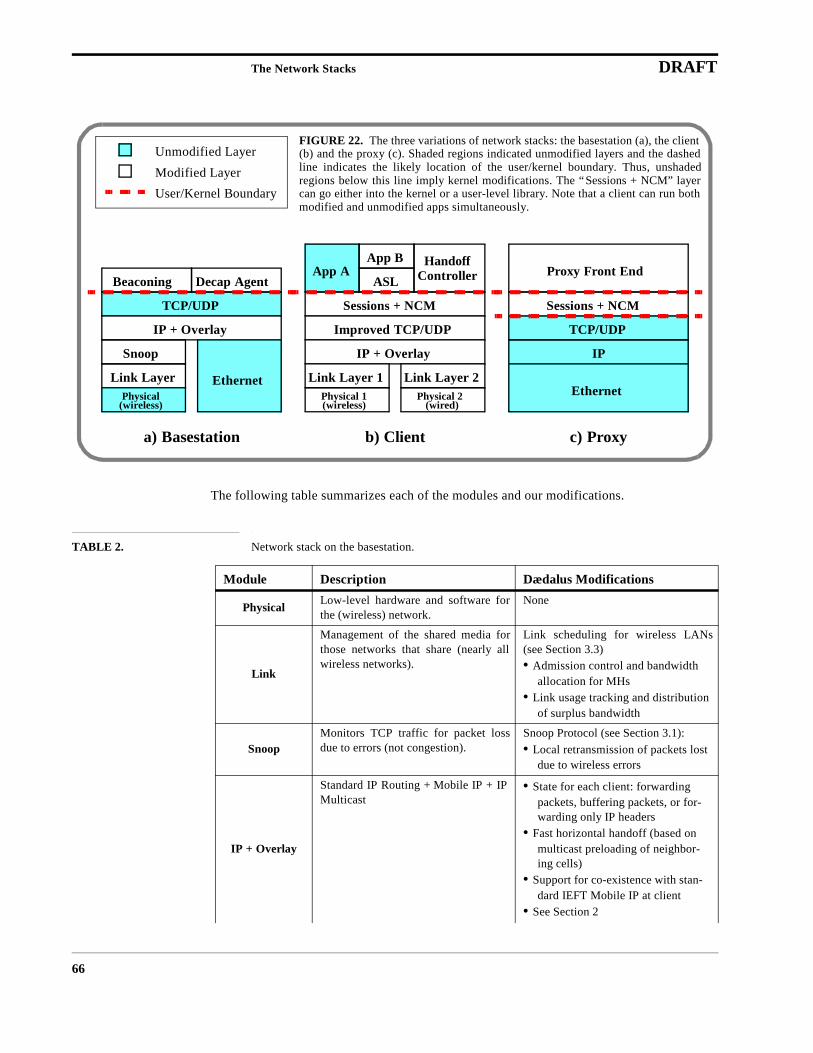
The Network Stacks DRAFT
66
The following table summarizes each of the modules and our modifications.
TABLE 2. Network stack on the basestation.
Module Description Dædalus Modifications
Physical Low-level hardware and software forthe (wireless) network.
None
Link
Management of the shared media forthose networks that share (nearly allwireless networks).
Link scheduling for wireless LANs(see Section 3.3)•Admission control and bandwidth
allocation for MHs•Link usage tracking and distribution
of surplus bandwidth
SnoopMonitors TCP traffic for packet lossdue to errors (not congestion).
Snoop Protocol (see Section 3.1):•Local retransmission of packets lost
due to wireless errors
IP + Overlay
Standard IP Routing + Mobile IP + IPMulticast
•State for each client: forwarding packets, buffering packets, or for-warding only IP headers
•Fast horizontal handoff (based on multicast preloading of neighbor-ing cells)
•Support for co-existence with stan-dard IEFT Mobile IP at client
•See Section 2
EthernetPhysical
(wireless)
Link Layer
IP + Overlay
TCP/UDP
Beaconing
Unmodified Layer
Modified Layer
Physical 1(wireless)
Link Layer 1
IP + Overlay
Improved TCP/UDP
Sessions + NCM
Ethernet
IP
TCP/UDP
Sessions + NCM
Link Layer 2Physical 2
(wired)
App A Proxy Front EndApp B
ASL
User/Kernel Boundary
a) Basestation b) Client c) Proxy
FIGURE 22. The three variations of network stacks: the basestation (a), the client(b) and the proxy (c). Shaded regions indicated unmodified layers and the dashedline indicates the likely location of the user/kernel boundary. Thus, unshadedregions below this line imply kernel modifications. The “Sessions + NCM” layercan go either into the kernel or a user-level library. Note that a client can run bothmodified and unmodified apps simultaneously.
Snoop
Decap Agent
HandoffController

The Network Stacks DRAFT
67
6.2 The Client Network Stack
The client stack is also highly modified, and adds several new pieces to the stack from the bas-estation:
TCP/UDPStandard TCP/UDP. Used only tocommunicate with the basestation,rather than affecting client traffic.
None
Beaconing
Broadcasts network beacons for thiscell. Clients detect these beacons andcan then connect to the basestation.
•Notification of wired IP address•Name server location, See Section
5.2•Possible piggybacked data, See Sec-
tion 5.4
Decap Agent
Communicates with HandoffController on the client and controlsthe routing state and Foreign/Homeagent mapping in the IP + Overlaylayer.
•TCP communication with the client•Control over Overlay routing
TABLE 3. Network stack on the client.
Module Description Dædalus Modifications
Physical LayerLow-level hardware and software forthe (wireless) network.
•API for determining whether net-work interface is on/off and for measuring current signal quality
Link LayerManagement of the shared media forthose networks that share (nearly allwireless networks).
Link scheduling for wireless LANs •Enforcement of bandwidth allocation
IP + Overlay
Standard IP Routing, Mobile IP, and IPMulticast
•Track performance of multiple inter-faces
•Signal higher layers when they should re-examine the choice of network
•Support for co-existence with stan-dard IEFT Mobile IP in infrastruc-ture
TCP/UDPTCP/UDP with modifications forimproved performance on wireless andasymmetric networks.
•Selective acknowledgments•Asymmetric network enhancements•See Section 3
TABLE 2. Network stack on the basestation.
Module Description Dædalus Modifications
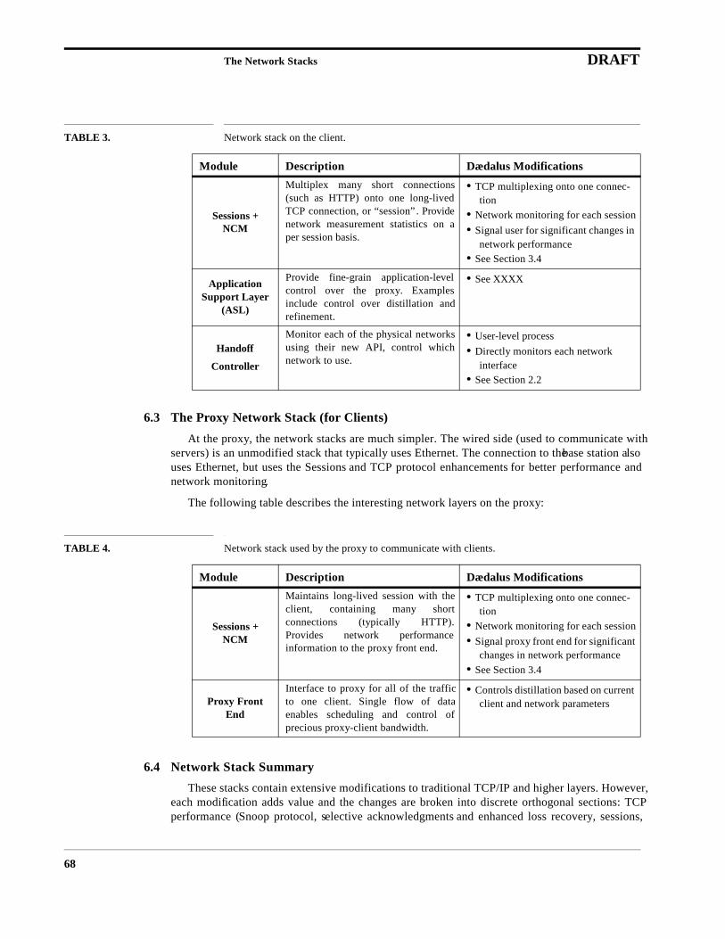
The Network Stacks DRAFT
68
6.3 The Proxy Network Stack (for Clients)
At the proxy, the network stacks are much simpler. The wired side (used to communicate withservers) is an unmodified stack that typically uses Ethernet. The connection to the base station alsouses Ethernet, but uses the Sessions and TCP protocol enhancements for better performance andnetwork monitoring.
The following table describes the interesting network layers on the proxy:
6.4 Network Stack Summary
These stacks contain extensive modifications to traditional TCP/IP and higher layers. However,each modification adds value and the changes are broken into discrete orthogonal sections: TCPperformance (Snoop protocol, selective acknowledgments and enhanced loss recovery, sessions,
Sessions + NCM
Multiplex many short connections(such as HTTP) onto one long-livedTCP connection, or “session”. Providenetwork measurement statistics on aper session basis.
•TCP multiplexing onto one connec-tion
•Network monitoring for each session•Signal user for significant changes in
network performance•See Section 3.4
ApplicationSupport Layer
(ASL)
Provide fine-grain application-levelcontrol over the proxy. Examplesinclude control over distillation andrefinement.
•See XXXX
Handoff
Controller
Monitor each of the physical networksusing their new API, control whichnetwork to use.
•User-level process•Directly monitors each network
interface•See Section 2.2
TABLE 4. Network stack used by the proxy to communicate with clients.
Module Description Dædalus Modifications
Sessions + NCM
Maintains long-lived session with theclient, containing many shortconnections (typically HTTP).Provides network performanceinformation to the proxy front end.
•TCP multiplexing onto one connec-tion
•Network monitoring for each session•Signal proxy front end for significant
changes in network performance•See Section 3.4
Proxy Front End
Interface to proxy for all of the trafficto one client. Single flow of dataenables scheduling and control ofprecious proxy-client bandwidth.
•Controls distillation based on current client and network parameters
TABLE 3. Network stack on the client.
Module Description Dædalus Modifications

The Network Stacks DRAFT
69
network connection monitoring), Overlay Networking, IETF Mobile IP compatibility, and proxyand application support. The network services modules (authentication, name server, etc.) have noeffect on the stacks, although the network services module affects the contents of beacons.

The Network Stacks DRAFT
70

Summary DRAFT
71
7 Summary
In this section, we revisit the original ten principles and summarize how each principle is metby the architecture. By implementing these principles, we also meet the larger goal: best-qualitymultimedia access anytime, anywhere with heterogeneous networks and clients in an infrastructurethat scales, remains available, and is easy to use.
7.1 The Principles Revisited
Principle 1: Heterogeneous Networks: The infrastructure must include wire-less networks that have a mixture of global and indoor coverage,thus requiring a heterogeneous collection of networks.
This principle is supported by a combination of Overlay Networking, TCP performance and theproxy. Overlay networking provides detection of the available networks and manages handoffsamong them, both vertically and horizontally. The TCP improvements mitigates problems withmany of the wireless networks, such as high error rates and asymmetry, and the proxy tunes thecontent to the available bandwidth, thus widening the range of practically useful networks.
Principle 2: Scalable: The infrastructure must scale to support millions ofusers.
We assume that the physical network is scalable; this is true in practice simply because there isno need for centralization. Similarly, the network services system is scalable because it is replicatedlocally. The challenge is to scale the proxy, which is a shared resource so that it can be amortizedover many users. The proxy has been redesigned for scalability using a NOW cluster and extensivemultithreading. It also exploits burstiness is user needs to increase the aggregate number of sup-ported clients.
Principle 3: Highly Available: The infrastructure must be available all of thetime.
We mostly assume the availability of individual networks such as Metricom. However, theoverlay networking concept increases overall availability dramatically by offering multiple net-working options. Thus the loss of an individual network need not imply loss of service. In addition,the proxy and network services systems provide highly available service through replication, auto-matic failover, and fast restart of subsystems that fail. For example, the PTM has a primary and sec-ondary and distillers will restart the PTM if they detect that it has failed.
Principle 4: Transparent Access: The detection and setup of a network con-nection should be automatic. Users shouldn’t have to know whatnetworks are in range.
The principle is implemented by overlay networking and by the network services system. Inparticular, overlay network handles the detection of networks and automatic connection to them,while the services module provides automated location of common critical services such as DNS,e-mail, and proxies. Thus users get access to all of these resources (and many others) simply bybeing in range of a Dædalus-aware network.
Principle 5: Localized Service: The detection and setup of local network ser-vices should be automatic. Users shouldn’t have to know whatservices are available at their current location.
Summary DRAFT
72
This principle is the driving force behind the network services system. It handles the detectionof available services, automatic connection to critical services (like DNS), and even dynamicextension of the client with new (local) abilities though code mobility.
Principle 6: Global Authentication: We must authenticate users using a glo-bally available security infrastructure, such as public-key cryp-tography or Kerberos.
Authentication is handled mostly by Kerberos, but we have extended Kerberos to impoverishedclients via Charon, which is part of the network services module. This allows reliable end-to-endauthentication that exploits the infrastructure without having to trust it. We use Kerberos’ cross-realm authentication protocol to handle mobile hosts that appear in a foreign (untrusted) environ-ment.
Principle 7: Multimedia: The infrastructure must support graphics, audioand video in addition to text.
Multimedia support comes from the proxy, the optimized transport layer, and even overlay net-working. The proxy tunes multimedia to the current format and bandwidth requirements, thusenabling multimedia access in situations where it was previously impossible. The use of deliveryclasses allows the network to understand the transmission requirement of multimedia data and opti-mize and prioritize accordingly. Finally, the overlay system provides fast handoff by prechargingneighboring cells, which enables smooth audio and video across handoffs.
Principle 8: Performance: The user’s data should arrive as fast as possible.This includes selecting the best network, optimizing the networkperformance, and optimizing the content at the application level.
The optimal performance for the current client device and location comes from the combinationof the TCP optimizations, the overlay networking module, and the proxy. TCP optimizations miti-gate wireless errors, improve throughput with long-lived sessions and support for asymmetric net-works, and improve utilization through delivery classes and scheduling for shared links. Theoverlay module helps by selecting the best network for the current location. Finally, the proxygreatly improves performance (especially latency) by tuning the content for the current networkconditions, which it knows through network monitoring of the session with each client.
Principle 9: Heterogeneous Clients: Complexity should be pushed into theinfrastructure, where it can be amortized over all of the activeusers. The infrastructure should support both inexpensive clientdevices, such as smart phones, and more sophisticated comput-ers, such as high-end laptops.
This is the driving force behind the proxy architecture. The only way handle both widely heter-ogeneous clients and legacy servers is to adapt content dynamically for each client. The scalableproxy solves this problem efficiently through datatype-specific distillation and refinement, andthrough a scalable extendable architecture.
Principle 10: Dynamic Adaptation: The data sent to the user should be opti-mized for timeliness, carrying the most information in the leastamount of time. The nature of this adaptation depends on the cur-rent network, the preferences of the user, and the nature of thedata (text is much different than graphics).
Summary DRAFT
73
This principle is also tightly tied to the proxy. The proxy knows current network conditions,tracks user preferences, caches object before and after transformation, and knows the nature of thedata because of the use of MIME types and datatype-specific distillation. This information, com-bined with fast (real-time) transformation engines, allows the proxy to customize content com-pletely for each client individually on every access.
7.2 Summary
Finally, we return to our original high-level goal:
“People and their machines should be able to access information and communicatewith each other easily and securely, in any medium or combination of media —voice, data, image, video, or multimedia — any time, anywhere, in a timely, cost-effective way.”
Dr. George H. HeilmeierIEEE Communication
October 1992
How far are we away from this goal given our architecture? We believe that we have provided asolution that handles the easy and secure multimedia access aspects, and provides timely cost-effective service. The remaining issue is that of “any time, anywhere.” Assuming the wide deploy-ment of wireless networks, which is a big assumption, we believe this architecture meets thesegoals as well. In particular, overlay networking and the scalable, highly available infrastructureallow clients to use any available network to obtain best-quality network access any time, anywhere(supported by at least one network).

Summary DRAFT
74
Glossary DRAFT
75
8 Glossary
ASL See Application Support Layer, XXXX
BARWAN Bay Area Research Wireless Access Network: The testbed used in our projectto interoperate multiple wireless networks. The testbed currently includesWaveLAN, IR, Metricom, Hughes DBS, CPDP, and cable modems.
Basestation The transmitter and router for a single cell of a wireless network. Typically,the BS is connected via ethernet to the infrastructure components and pro-vides beaconing, forwarding, and some measurement and control over thecell.
Black-Box BS A Basestation that we have no control over in terms of modifying code run-ning on the basestation. Examples are CDPD and Metricom.
Beacon Agent This agent sends out periodic beacon packets that are similar to Mobile IPagent advertisements but may also contain additional information
BS See Basestation
CB See Coordination Bus
COA See Care-Of Address
Care-Of Address The visited locale’s temporary address for a mobile host, advertised to thehome agent (and to corresponding hosts using route optimization)
Cell A not necessarily contiguous physical area covered by a single transmitter ina wireless network. Cells may overlap with both other cells of the same net-work and with cells of other wireless networks.
Channel A multicast group with a symbolic name that can be looked up via the nameserver. It is the unit of grouping in the coordination bus.
Coordination Bus This is the shared communication medium among the modules that collec-tively form the proxy. The bus consists of a number of named channels towhich any module can broadcast or listen. Channels map one-to-one withmulticast IP addresses and the name server maps channel names to theseaddresses.
Dædalus The networking half of this project, which includes all of the TCP and hand-off stuff.
DBS Direct Broadcast Satellite
Decapsulation Agent This agent receives messages from the Handoff Controller and modifiesOverlap IP’s kernel-level translation tables in response to these messages.
DHCP Dynamic Host Configuration Protocol. This protocol can be used to assign alocal IP address to a device that just joined the local network.
FA See Foreign Agent
Foreign Agent This entity resides in “visited” systems, advertises its presence, and is usedto obtain a temporary care-of address (either multicast or unicast) for amobile host.
Glossary DRAFT
76
GloMop The application services half of this project, which includes the proxy andsecurity aspects.
HA See Home Agent
Handoff The change from one network connection to another. Ideally, this transfer istransparent to the application. If done at the link layer, which is common forhorizontal handoffs, it is transparent even to TCP.
Handoff Controller This component handles the transition when a mobile device moves fromone base station to another (horizontal handoff) or when a mobile devicemoves from one network to another (vertical handoff). It sends the encapsu-lation/decapsulation requests to the decapsulation agent. It makes all handoffdecisions due to mobility by listening to beacon packets sent by the beacon-ing agent.
Home Agent As in Mobile IP: A router on a mobile node’s home network which tunnelsdatagrams for delivery to the mobile node to its Care-Of Address when it isaway from home, and maintains current location information for the mobilenode.
Horizontal Handoff A handoff between cells within the same physical network, such as from oneMetricom pole-top basestation to another.
Metricom Makers of the Ricochet packet radio modem. The Metricom network is ahalf-duplex store-and-forward network that is deployed in the Bay Area,Portland, and Washington, D.C. The bandwidth is about 30 kbps, but thelatency can be seconds.
MH See Mobile Host
MN See Mobile Node
Mobile Host This is the client device; See Mobile Node
Mobile Node This terminology comes from Mobile IP: A host or router that changes itspoint of attachment from one network or subnetwork to another. A mobilenode may change its location without changing its IP address; it may con-tinue to communicate with other Internet nodes at any location using its(constant) IP address, assuming link-layer connectivity to a point of attach-ment is available.
Mobile IP An extension to IP that supports mobility by forwarding packets through ahome agent, which tracks the location of the mobile host.
NCM Network Connection Monitor: Part of the sessions functionality that providesfeedback on the current state of the session. Statistics collected include thepacket loss rate and effective bandwidth of the transport-level connection.
Overlay IP Extensions to IP that support mobility and handoff across different networks.
Proxy A well-connected node that acts as an intermediary and translator betweenpoorly connected, heteregeneous clients and the rest of the internet.
PTM Proxy Transcoder Manager: The PTM manages distillers for the proxy frontends. It controls a pool of distillers for each data type, provides load balanc-ing, and handles spawning and killing distillers as the overall load variesover time.
Glossary DRAFT
77
Ricochet See Metricom
Session A long-lived connection over which many short TCP connections are multi-plexed. It also provides connection statistics using the NCM.
User Control Panel This allows user-specific customization about the choice of network or basestation to connect to as well as the choice of handoff policy to use (e.g.aggressive low-latency handoff vs. less aggressive high-latency handoff).
Vertical Handoff A handoff between different networks, such as from IR to WaveLAN.
VGW See Video Gateway
Video Gateway A distiller for real-time video traffic.
WaveLAN A radio-based local-area wireless network.

Glossary DRAFT
78
References DRAFT
79 of 80
9 References
[ABSK95] E. Amir, H. Balakrishnan, S. Seshan, and R. H. Katz. Efficient TCP over Networks withWireless Links. Proc. Fifth Workshop on Hot Topics in Operating Systems (HotOS-V), OrcasIsland, WA, May 1995.
[AMZ95] E. Amir, S. McCanne and H. Zhang. An Application Level Video Gateway. In Proc. ACMMultimedia ’95, San Francisco, CA, November 1995.
[Ardis] Ardis web page. http://www.ardis.com, 1996.
[BDH+94] C. M. Bowman, P. B. Danzig, D. R. Hardy, U. Manber, M. F. Schwartz, and D. P. Wessels.Harvest: A Scalable, Customizable Discovery and Access System. Technical Report CU-CS-732-94, Department of Computer Science, University of Colorado, Boulder, August 1994(revised March 1995). ftp://ftp.cs.colorado.edu/pub/cs/techreports/schwartz/Harvest.Jour.ps.Z.
[BSAK95] H. Balakrishnan, S. Seshan, E. Amir, R. H. Katz. Improving TCP/IP Performance overWireless Networks. Proc. 1st ACM Conf. on Mobile Computing and Networking, Berkeley,CA, November 1995. Best Student Paper Award.
[BSK95] H. Balakrishnan, S. Seshan, R. H. Katz. Improving TCP/IP Reliable Transport and HandoffPerformance in Cellular Wireless Networks. ACM WirelessNetworks, 1(4), December 1995.
[Cac95] R. Caceres and L. Iftode. Improving the Performance of Reliable Transport Protocols in MobileComputing Environments. IEEE Journal on Selected Areas in Communications, 13(5), June1995.
[CDPD] V. Garg and J. Wilkes. Wireless and Personal Communications Systems. Prentice-Hall, 1996.Chapter 8.
[DN95] Antonio DeSimone, Sanjiv Nanda. Wireless Data: Systems, Standards, Services. In WirelessNetworks 1 (1995) 241-253.
[FJ95] Sally Floyd, Van Jacobson. Link-Sharing and Resource Management Models for PacketNetworks. In IEEE/ACM Transactions on Networking, Vol 3, No 4, August 1995.
[FG96] A. Fox, S. D. Gribble. Security On the Move: Indirect Authentication Using Kerberos. Proc.2nd ACM Conference on Mobile Computing and Networking (MOBICOM 96), Rye, NY,October 1996.
[FGBA96] A. Fox, S. D. Gribble, E. A. Brewer, E. Amir. Adapting to Network and Client Variability viaOn-Demand Dynamic Distillation. Proc. Seventh International Conference on ArchitecturalSupport for Programming Languages and Operating Systems (ASPLOS-VII), Cambridge, MA,May 1996.
[HH94] Andy Harter and Andy Hopper. A Distributed Location System for the Active Office. IEEENetwork Magazine, 8(1), January 1994.
[IDM91] J. Ioannidis, D. Duchamp, and G. Maguire. IP-Based Protocols for Mobile Internetworking. InACM SIGCOMM Symposium on Communications, Architecture, and Protocols, pages 235-245,1991.
[LM96] G. Liu and G. Maguire, Jr., A Class of Mobile Prediction Algorithms for Wireless MobileComputing and Communications. In Journal on Special Topics in Mobile Networks andApplications, Volume 1(1996), No. 2.
[Jac88] V. Jacobson. Congestion avoidance and control. In Proc. of SIGCOMM ’88, August 1988.
[Lee94] J. s. Lee. Overview of the technical basis of qualcomm’s cdma cellular telephone systemdesign: a view of north american tia/eia is-95. In Proc ICCS ’94, volume 2, pages 353–358,Nov 1994.
[Per96] C. Perkins. IP Mobility Support. RFC-2002, October 1996.

References DRAFT
80 of 80
[PM94] V. N. Padmanabhan and J. C. Mogul. Improving HTTP Latency. In Proc. Second InternationalWorld Wide Web Conference, October 1994.
[Ricochet] Metricom web page. http://www.metricom.com, 1996.
[SAG+93] Bill N. Schilit, Norman Adams, Rich Gold, Michael Tso, and Roy Want. The PARCTABMobile Computing System. In Proceedings Fourth Workshop on Workstation OperatingSystems (WWOS-IV), pages 34-39. IEEE, October 1993.
[Ses95] S. Seshan. Low Latency Handoffs in Cellular Data Networks. Ph.D. thesis, University ofCalifornia at Berkeley, December 1995.
[Ste88] J. G. Steiner, C. Neuman, and J. I. Schiller. Kerberos: an authentication service for opennetwork systems. In Proceedings of the USENIX Winter Conference 1988, pages 191–202,Dallas, Texas, USA, February 1988.
[Ste96] M. Stemm. Vertical Handoffs in Wireless Overlay Networks. M.S. Report, University ofCalifornia at Berkeley, May 1996.
[Ste94] W. R. Stevens. The TCP/IP Illustrated, Volume 1. Addison-Wesley, Reading, MA, Nov 1994.
[Ste97] M. Stemm and R. H. Katz Vertical Handoffs in Wireless Overlay Networks. ACM MobileNetworking, Special Issue on Mobile Networking in the Ineternet, Fall 1997.
[Tek91] Tekinay S. and B. Jabbari. Handover and Channel Assignment in Mobile Cellular Networks.IEEE Communications Magazine, 29(11):42–46, November 1991.
[Zha86] L. Zhang. Why TCP Timers Don’t Work Well. In Proceedings of ACM SIGCOMM ’86, pages397–405, August 1986.