A Multi-Broadcast Communication System for High...
7
Abstract—The implementation of Safety of Life (SoL) services in transportation systems, e.g. for applications like collision avoidance of vehicles, requires reliable and instantaneous information exchange. In this paper we present the design of an infrastructure-less ad-hoc inter-vehicle communication system that fulfills these requirements with respect to the boundary conditions in the railway environment, where a limited communication range and relatively high speeds of nodes cause the network to be highly dynamic. Moreover, in areas with high user densities the common media access is a challenge due to limited bandwidth and interference from other wireless systems. I. INTRODUCTION TATISTICS of the International Union of Railways (UIC) show, that there are three significant train accidents in Europe every day [1], despite of millions of Euros which have been invested in trackside and in-train safety equipment. Even with Automatic Train Control (ATC) systems like the future European Train Control System (ETCS) a significant amount of accidents cannot be prevented, because they occur between trains and other kinds of obstacles like construction vehicles, construction workers or pedestrians and vehicles on level crossings. In order to increase safety in railway traffic, a vehicle integrated collision avoidance system similar to the existing ones in maritime or air transportation [2], is proposed. Conceptual this provides a safety overlay level that would take effect in situations that caused most accidents in recent years The advantages are higher safety as well as more efficient use of railways on an international level at low cost and without changes to existing infrastructure and independent of the various railway control mechanisms. Usually such systems rely on position determination and direct communication among vehicles as illustrated in Fig. 1. Each railroad vehicle shall be equipped with onboard sensors that provide updated Position, Velocity and Time (PVT) information. PVT and additional data is then regularly broadcasted to all other RCAS (Railway Collision Avoidance System) equipped units in the surrounding. By analyzing the received messages from other units the complete traffic situation can be assessed, thereby allowing the in-time warning and advising of a train driver in case of a collision threat, long before the danger is visible and early enough to completely avoid it. In order to prevent accidents with single carriages, vehicles on level crossings or construction workers, these “users” can as well be equipped with RCAS units. Since braking distances of trains can be several kilometers, a sufficient range for the direct train-to-train communications link is required. On the other hand, bandwidth and power limitations put constraints on the maximum range. Moreover a reliable message transmission must be guaranteed in all the different scenarios within a railway network. While suitable solutions for the inter-vehicle communication link were developed for the maritime AIS (Automatic Identification System) and the aeronautical TCAS/ADS-B [3] (Traffic Alert and Collision Avoidance System / Automatic Dependent Surveillance - Broadcast), the railway specific boundary conditions necessitate a new design for RCAS and other applications where there are • (punctually) very high user densities, • the network dynamic is high due to a relatively short communication range and high user speeds, and • bandwidth limitation and/or robustness against interfering systems is mandatory. Fig. 1. Principle of collision avoidance based on the broadcast of traffic relevant information among vehicles, illustrated for the railway case. II. TOPOLOGICAL ASPECTS Topological scenarios describe the different parts of a transportation network. In an analysis published in [4], we investigated the different topological scenarios in railroad transport and identified • regional lines, • train stations • and shunting yards Multi-Broadcast Communication System for High Dynamic Vehicular Ad-hoc Networks Andreas Lehner, Cristina Rico-García, Eugen Wige, and Thomas Strang, Institute for Communications and Navigation, German Aerospace Center DLR S
Transcript of A Multi-Broadcast Communication System for High...

Abstract—The implementation of Safety of Life (SoL)
services in transportation systems, e.g. for applications like
collision avoidance of vehicles, requires reliable and
instantaneous information exchange. In this paper we present
the design of an infrastructure-less ad-hoc inter-vehicle
communication system that fulfills these requirements with
respect to the boundary conditions in the railway environment,
where a limited communication range and relatively high
speeds of nodes cause the network to be highly dynamic.
Moreover, in areas with high user densities the common media
access is a challenge due to limited bandwidth and interference
from other wireless systems.
I. INTRODUCTION
TATISTICS of the International Union of Railways (UIC) show, that there are three significant train
accidents in Europe every day [1], despite of millions of Euros which have been invested in trackside and in-train safety equipment. Even with Automatic Train Control (ATC) systems like the future European Train Control System (ETCS) a significant amount of accidents cannot be prevented, because they occur between trains and other kinds of obstacles like construction vehicles, construction workers or pedestrians and vehicles on level crossings.
In order to increase safety in railway traffic, a vehicle integrated collision avoidance system similar to the existing ones in maritime or air transportation [2], is proposed. Conceptual this provides a safety overlay level that would take effect in situations that caused most accidents in recent years The advantages are higher safety as well as more efficient use of railways on an international level at low cost and without changes to existing infrastructure and independent of the various railway control mechanisms.
Usually such systems rely on position determination and direct communication among vehicles as illustrated in Fig. 1. Each railroad vehicle shall be equipped with onboard sensors that provide updated Position, Velocity and Time (PVT) information. PVT and additional data is then regularly broadcasted to all other RCAS (Railway Collision Avoidance System) equipped units in the surrounding. By analyzing the received messages from other units the complete traffic situation can be assessed, thereby allowing the in-time warning and advising of a train driver in case of a collision threat, long before the danger is visible and early enough to completely avoid it. In order to prevent accidents with single carriages, vehicles on level crossings or construction workers, these “users” can as well be equipped with RCAS units.
Since braking distances of trains can be several kilometers, a sufficient range for the direct train-to-train communications link is required. On the other hand, bandwidth and power limitations put constraints on the maximum range. Moreover a reliable message transmission must be guaranteed in all the different scenarios within a railway network.
While suitable solutions for the inter-vehicle communication link were developed for the maritime AIS (Automatic Identification System) and the aeronautical TCAS/ADS-B [3] (Traffic Alert and Collision Avoidance System / Automatic Dependent Surveillance - Broadcast), the railway specific boundary conditions necessitate a new design for RCAS and other applications where there are
• (punctually) very high user densities, • the network dynamic is high due to a relatively
short communication range and high user speeds, and
• bandwidth limitation and/or robustness against interfering systems
is mandatory.
Fig. 1. Principle of collision avoidance based on the broadcast of traffic relevant information among vehicles, illustrated for the railway case.
II. TOPOLOGICAL ASPECTS
Topological scenarios describe the different parts of a transportation network. In an analysis published in [4], we investigated the different topological scenarios in railroad transport and identified
• regional lines, • train stations • and shunting yards
Multi-Broadcast Communication System for High Dynamic
Vehicular Ad-hoc Networks
Andreas Lehner, Cristina Rico-García, Eugen Wige, and Thomas Strang, Institute for Communications and Navigation, German Aerospace Center DLR
S
as those scenarios which are relevant for the RCAS system design. Main lines with high speed services are not considered, because there the safety level is already very high due to extensive technical equipment and train control mechanisms.
For the listed scenarios the maximum speed is 200 km/h. In case of emergency braking the maximum braking distances are in the order of 1 km. Depending on the weather and rail conditions this can increase due to reduced fraction. Moreover, to allow for a secure (non passenger imperilling) braking of fast passenger trains, more than 2 km are necessary with the corresponding brake configuration. For a head-on collision scenario this means we need to guarantee a communication range of at least 5 km and need to have a high message repetition rate to loose a minimum of braking distance when the two trains approach the communication range.
More constraints arise from the high rail vehicle densities in large shunting yards. To avoid any collisions of railroad vehicles, each carriage has to regularly transmit its position and status.
III. RCAS ARCHITECTURE
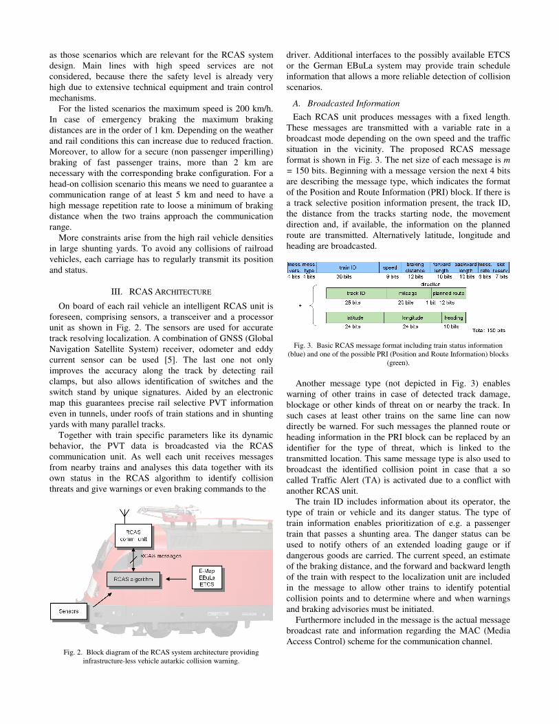
On board of each rail vehicle an intelligent RCAS unit is foreseen, comprising sensors, a transceiver and a processor unit as shown in Fig. 2. The sensors are used for accurate track resolving localization. A combination of GNSS (Global Navigation Satellite System) receiver, odometer and eddy current sensor can be used [5]. The last one not only improves the accuracy along the track by detecting rail clamps, but also allows identification of switches and the switch stand by unique signatures. Aided by an electronic map this guarantees precise rail selective PVT information even in tunnels, under roofs of train stations and in shunting yards with many parallel tracks.
Together with train specific parameters like its dynamic behavior, the PVT data is broadcasted via the RCAS communication unit. As well each unit receives messages from nearby trains and analyses this data together with its own status in the RCAS algorithm to identify collision threats and give warnings or even braking commands to the
Fig. 2. Block diagram of the RCAS system architecture providing infrastructure-less vehicle autarkic collision warning.
driver. Additional interfaces to the possibly available ETCS or the German EBuLa system may provide train schedule information that allows a more reliable detection of collision scenarios.
A. Broadcasted Information
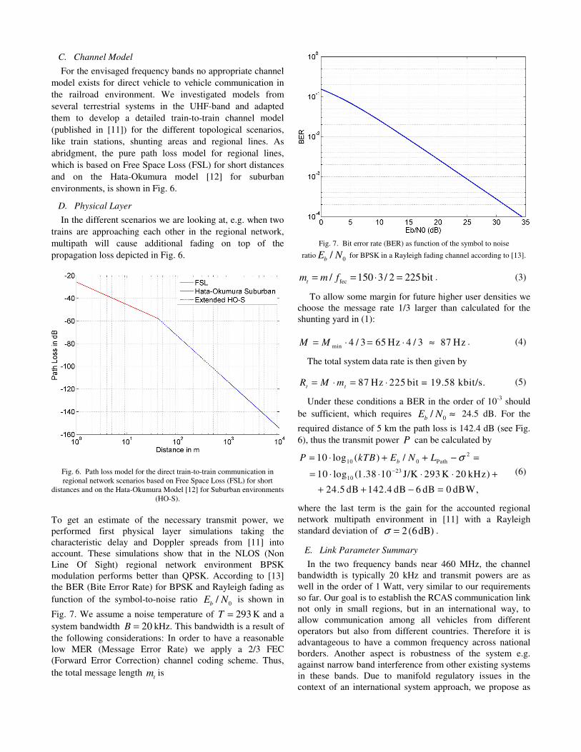
Each RCAS unit produces messages with a fixed length. These messages are transmitted with a variable rate in a broadcast mode depending on the own speed and the traffic situation in the vicinity. The proposed RCAS message format is shown in Fig. 3. The net size of each message is m
= 150 bits. Beginning with a message version the next 4 bits are describing the message type, which indicates the format of the Position and Route Information (PRI) block. If there is a track selective position information present, the track ID, the distance from the tracks starting node, the movement direction and, if available, the information on the planned route are transmitted. Alternatively latitude, longitude and heading are broadcasted.
Fig. 3. Basic RCAS message format including train status information (blue) and one of the possible PRI (Position and Route Information) blocks
(green).
Another message type (not depicted in Fig. 3) enables
warning of other trains in case of detected track damage, blockage or other kinds of threat on or nearby the track. In such cases at least other trains on the same line can now directly be warned. For such messages the planned route or heading information in the PRI block can be replaced by an identifier for the type of threat, which is linked to the transmitted location. This same message type is also used to broadcast the identified collision point in case that a so called Traffic Alert (TA) is activated due to a conflict with another RCAS unit.
The train ID includes information about its operator, the type of train or vehicle and its danger status. The type of train information enables prioritization of e.g. a passenger train that passes a shunting area. The danger status can be used to notify others of an extended loading gauge or if dangerous goods are carried. The current speed, an estimate of the braking distance, and the forward and backward length of the train with respect to the localization unit are included in the message to allow other trains to identify potential collision points and to determine where and when warnings and braking advisories must be initiated.
Furthermore included in the message is the actual message broadcast rate and information regarding the MAC (Media Access Control) scheme for the communication channel.

IV. COMMUNICATION LINK DESIGN
A. Maximum system data rate
Dependent on the transportation system and on the concrete application or service, we have different requirements on the inter-vehicle communication system capacity. In case of multi-broadcast communication for collision avoidance in the railway environment, the highest data transmission rate is necessary in the shunting yard scenario within a regional network, where we face possibly large speeds and high user densities.
At Europe’s largest shunting yard in Maschen near Hamburg in Germany, several hundred trains with more than 4000 freight carriages are handled per day [6]. The yard is more than 5 km long and has 48 and 64 parallel tracks on the two classification bowls, respectively (Fig. 4). The detail in Fig. 4 shows a snapshot of a typical shunting situation. In this situation we can identify about 200 static “trains”, i.e. lines of connected railroad vehicles, in the complete area of the shunting yard. In addition about 25 trains or engines, that are likely to move, are visible.
Fig. 4. Europe’s largest shunting yard in Maschen near Hamburg in Germany has a length of more than 5 km. Several hundred trains with more
than 4000 carriages are shunted every day.
As explicated in [7], the message transmission rate can be adopted in a certain range to the traffic situation and the speed of the vehicle without noticeable degradation of the performance of the complete collision avoidance system. If we assume that an average rate of 0.2 Hz and 1 Hz for static and moving trains, respectively, is sufficient, than the minimum required system message rate minM is given by
static movemin static move
200 0.2 Hz 25 1Hz = 65 Hz,
M N M N M= ⋅ + ⋅ =
= ⋅ + ⋅
(1)
and the net system data rate is
net min 65 Hz 150 bit = 9.75 kbit/s.R M m= ⋅ = ⋅ (2)
Since the required communication range for the RCAS approach is 5 km, the final system design has to take the fact into account that the area of the depicted scenario in Fig. 4 is about four times smaller. Thus, some margin for data from trains in the vicinity has to be added for the final link design.
B. Frequency Selection
A very important design step is the selection of the frequency band in order to allow a reliable inter-vehicle communication in the various operational and topological scenarios on railroads. In contrast to GSM-R at about 900 MHz, which is a communication standard for data and voice based on GSM for European high speed trains using base stations of sufficient height, the direct train-to-train communication in RCAS is intended to be used in regional networks, where the lines are not so straight, and of course the antennas are just mounted on top of the rail vehicles. That means, we face a much higher propagation loss in case of direct vehicle-to-vehicle communication.
More appropriate for low antenna heights in the railway environment are frequencies in the lower UHF band, where certain wave guiding effects are likely. On regional lines the curve radii are larger than 160 m and the narrow clean area beside the track is at least 11 m [8]. Cuttings on both sides of the track, crossings through forests and even tunnels can cause certain wave guidance at these frequencies [9].
In Japan a band at 300 MHz is allocated for such applications, whereas in USA and Canada two bands at 160 MHz and 455 MHz are utilized (see Fig. 5). For Europe we found two suitable bands from 456-459 MHz and 460-470 MHz that were marked for railway communication services by the European Radiocommunications Committee (ERC) [10].
Fig. 5. Worldwide dedicated frequency bands for railway wireless communication services.
The transmit power and bandwidth in the envisaged
frequency bands around 460 MHz is limited due to regulatory issues and concurrent narrow band systems. Thus we have a strong limit on the data rate, which means we have to use the message bits including the channel coding economically and we need to hold the message rate low. This is contradictory to the head-on collision scenario of two fast passenger trains, where we want to detect the threat as early as possible. One part of the solution is to adapt the message rate as described in detail in [7].
C. Channel Model
For the envisaged frequency bands no appropriate channel model exists for direct vehicle to vehicle communication in the railroad environment. We investigated models from several terrestrial systems in the UHF-band and adapted them to develop a detailed train-to-train channel model (published in [11]) for the different topological scenarios, like train stations, shunting areas and regional lines. As abridgment, the pure path loss model for regional lines, which is based on Free Space Loss (FSL) for short distances and on the Hata-Okumura model [12] for suburban environments, is shown in Fig. 6.
D. Physical Layer
In the different scenarios we are looking at, e.g. when two trains are approaching each other in the regional network, multipath will cause additional fading on top of the propagation loss depicted in Fig. 6.
Fig. 6. Path loss model for the direct train-to-train communication in regional network scenarios based on Free Space Loss (FSL) for short
distances and on the Hata-Okumura Model [12] for Suburban environments (HO-S).
To get an estimate of the necessary transmit power, we performed first physical layer simulations taking the characteristic delay and Doppler spreads from [11] into account. These simulations show that in the NLOS (Non Line Of Sight) regional network environment BPSK modulation performs better than QPSK. According to [13] the BER (Bite Error Rate) for BPSK and Rayleigh fading as function of the symbol-to-noise ratio 0/
bE N is shown in
Fig. 7. We assume a noise temperature of 293T = K and a system bandwidth 20B = kHz. This bandwidth is a result of the following considerations: In order to have a reasonable low MER (Message Error Rate) we apply a 2/3 FEC (Forward Error Correction) channel coding scheme. Thus, the total message length
tm is
Fig. 7. Bit error rate (BER) as function of the symbol to noise
ratio 0/b
E N for BPSK in a Rayleigh fading channel according to [13].
fec/ 150 3/ 2 225bitt
m m f= = ⋅ = . (3)
To allow some margin for future higher user densities we choose the message rate 1/3 larger than calculated for the shunting yard in (1):
min 4 / 3 65 Hz 4 / 3 87 HzM M= ⋅ = ⋅ ≈ . (4)
The total system data rate is then given by
87 Hz 225 bit = 19.58 kbit/s.t t
R M m= ⋅ = ⋅ (5)
Under these conditions a BER in the order of 10-3 should be sufficient, which requires 0/
bE N ≈ 24.5 dB. For the
required distance of 5 km the path loss is 142.4 dB (see Fig. 6), thus the transmit power P can be calculated by
210 0 Path
2310
10 log ( ) /
10 log (1.38 10 J/K 293 K 20 kHz)
24.5 dB 142.4 dB 6 dB 0 dBW,
bP kTB E N L σ
−
= ⋅ + + − =
= ⋅ ⋅ ⋅ ⋅ +
+ + − =
(6)
where the last term is the gain for the accounted regional network multipath environment in [11] with a Rayleigh standard deviation of 2(6dB)σ = .
E. Link Parameter Summary
In the two frequency bands near 460 MHz, the channel bandwidth is typically 20 kHz and transmit powers are as well in the order of 1 Watt, very similar to our requirements so far. Our goal is to establish the RCAS communication link not only in small regions, but in an international way, to allow communication among all vehicles from different operators but also from different countries. Therefore it is advantageous to have a common frequency across national borders. Another aspect is robustness of the system e.g. against narrow band interference from other existing systems in these bands. Due to manifold regulatory issues in the context of an international system approach, we propose as
solution the appliance of a spreading technique. For the 10 MHz band from 460-470 MHz we could modulate each message bit with a 511 chip Gold code, which allows us to summarize the multi-broadcast train-to-train link parameters as follows:
TABLE I MULTI-BROADCAST TRAIN-TO-TRAIN LINK PARAMETER SUMMARY
Modulation BPSK Frame length 1s Slots/frame 87 (TS = 11.5 ms) Channel coding 2/3 rate FEC Bits/message 225 (TB = 51 ms) CDMA code
511 bit Gold code (TC = 0.1 ms → 10 MHz bandwidth)
Note that the necessary system message rate calculated in
(1) is well exceeded by providing 87 (message) slots per second. Given that the channel access scheme allows for a low message collision rate, a reliable information exchange with low latencies is thus possible even under heavy load of the system. Furthermore this approach guarantees a European wide common frequency, robustness against other narrow band systems, as well as a relatively low interfering power (a few mW) to these systems. Moreover a combined TDMA and CDMA access scheme offers significant improvement on the MAC layer as described next.
V. MEDIA ACCESS CONTROL
The core feature of an ad-hoc network is to provide communication services without any infrastructure or centralized access point. There is no base station to coordinate packet transmissions. Thus, the MAC protocol must be accomplished in a distributed way. Since channel resources are limited, transmissions are likely to interfere with those from other users in the vicinity that also have packets to transmit in the same channel. This problem becomes more critical for increasing number of users. Moreover, the faster the network changes, the harder it becomes to organize the access of the channel.
The simplest protocol for MAC layers that can be used is the well known ALOHA protocol [14] where no control is used. However due to its low throughput it is only applicable in low density ad-hoc networks, like for instance for the TCAS system in aeronautics, where there are maximal 30 nodes within the communication range of 56 km [3]. Another of the earliest mechanisms adopted was the CSMA (Carrier Sense Medium Access) protocol [15]. Nonetheless, it introduces the hidden terminal and exposed terminal problem. But also protocols using handshake are not suited for RCAS, as they are very inefficient for multi-broadcast services in Vehicular Ad-hoc Networks (VANET).
More adequate MAC protocols for our needs are related to TDMA, FDMA or CDMA. In this group we can find the Self Organized Time Division Multiple Access (SOTDMA) [16] protocol that is used by AIS in the maritime domain to avoid collisions of ships. This protocol is based on systematic slot reservations. However, as the speed and the transmitters’
density increases, the number of packet collisions due to the hidden terminal problem increases and long latency times, which are very critical for our application, can occur when two nodes are repeatedly reserving the same slot. Table II compares the boundary conditions for vehicle collision avoidance based on multi-broadcast communications for the different transportation systems. We define the topological network dynamic as the quotient of maximum node velocity and minimal communication range. This comparison shows that the RCAS network changes fastest and at the same time has the highest number of nodes within range. For this comparison the minimum communication range, the maximum velocity and the maximum number of nodes within the range are taken from the specifications of the AIS and TCAS system summarized in [2].
TABLE II COMPARISON OF NETWORK DYNAMIC AND NODE DENSITY FOR COLLISION
AVOIDANCE APPLICATION IN DIFFERENT TRANSPORTATION SYSTEMS Transport
system Min.
comm. range
Maximum velocity
Topological network
dynamics
Max. number of
nodes within range
Ships - AIS SOTDMA
40 km
60 km/h
1,5 h-1
75
Airplanes - TCAS ALOHA
56 km
1000 km/h
16 h-1
30
Trains - RCAS COMB
5 km
200 km/h
40 h-1
250
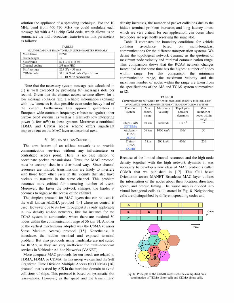
Because of the limited channel resources and the high node density together with the high network dynamic it was necessary to develop a new class of MAC protocols called COMB that we published in [17]. This Cell based Orientation aware MANET Broadcast MAC layer utilizes the information of the nodes about their location, direction, speed, and precise timing. The world map is divided into virtual hexagonal cells as illustrated in Fig. 8. Neighboring cells are distinguished by different spreading codes and
Fig. 8. Principle of the COMB access scheme exemplified on a combination of TDMA (inter-cell) and CDMA (intra-cell).

within a cell SOTDMA is applied. The dimension, i.e. the diameter, of the cell should be in the order of the range of the nodes. This way, every node in any position inside a cell is able to receive signals from the other nodes of the same cell. Furthermore, since messages from other cells are received with another (orthogonal) code, there are no collisions due to the hidden terminal problem. The CDMA code used by a node is inferred according to its location in a cell calculated from its position.
If one node is going to move across a cell border it is aware of the slot reservations in the new cell and can thus reserve a free slot in advance. Even if several nodes from different cells enter within the same frame their slot reservation can be prioritized as described in [17]. That is, in theory COMB can completely avoid data packet collisions even in case of a fully loaded system.
A. Simulations
On order to verify the performance of the proposed MAC layer we developed a time-triggered simulation environment for vehicular networks. The basic structure with the implemented modules is shown in Fig. 9.
Fig. 9. Class diagram of the MAC simulation environment for vehicular networks.
The simulator object creates the simulation environment
that has been defined in a parameter file. Such a simulator object generates a channel model, a CDMA environment, a route network and in our case the trains for this simulation. The trains provide the interfaces to the communication model and the movement model. The movement model describes the movement behavior of the trains (e.g. speed, acceleration, position) and uses therefore the routes network which consists of various routes. The communication model describes the behavior of the radio transmissions, according to the used MAC protocol. It defines which steps are executed in each TDMA slot (e.g. medium observation, receiving and transmitting the messages). The message model contains all the information that is given due to the transmissions from the different participants in the network, such as the ID (which participant sends the message), the power level of the message or the used CDMA code. If we use different CDMA codes, the communication model uses the CDMA environment object to determine in which CDMA cell a train is currently located. We call this the cell membership.
We made simulations for a worst case scenario in railways where we considered relatively high speeds in a shunting yard area with a high node density. The simulation area had a size of 25 by 25 km and was divided in cells of 5 km diameter similar to the illustration in Fig. 10. The number in the center of each cell corresponds with the used CDMA code. At least 12 different codes are necessary for the COMB approach to theoretically allow collision free channel access [17]. The cells are arranged in a way that repeated codes have a maximum distance as common in cellular networks. Trains (black circles in Fig. 10) with speeds uniformly distributed between 0 and 200 km/h moved on a randomly generated network of straight lines. Furthermore we took the challenging propagation characteristics of the regional train-to-train channel model into account.
Fig. 10. Illustration of the simulated area covered by virtual cells for the vehicular network simulation.
Although the chosen network of straight lines does not
reflect the geometrical reality of typical shunting yards, we consider this simple route network model as appropriate to compare the performance of various MAC protocols.
In Fig. 11 we compare COMB to the performance of slotted Aloha (blue dotted line). The red line indicates the theoretical limit of COMB, whereas the red stars show the simulation result taking the propagation channel into account. This degradation is a consequence of the near-far problem for the combination of Code and Time Division Multiple Access (CTDMA). In case of a fully loaded system in a future shunting yard environment (offered traffic = 1) the message collision rate is about 32 %. More important for the performance of the RCAS system is the distribution of message latencies in Fig. 12. Plotted is the probability that the time to receive an update from another

train (or the delay of the first message when entering the communication range) exceeds t seconds. Given a system load of 60 %, which corresponds to the current node density in Europe’s largest shunting yard, we see that in the case of COMB with fixed inter-cell slot reservation systematically repeated message collisions occur. This can be prevented by adding a random component (COMBR), in this example a casual slot change randomly after 5 to 10 seconds, without significant loss in throughput.
Fig. 11. Comparison of message collision rates between slotted Aloha and COMB in a worst case railway scenario.
Fig. 12. Message latency distributions for slotted Aloha within different CDMA cells, COMB with fixed slot reservation and COMBR (with casual
random slot changes) for a system load of 60 %.
VI. CONCLUSION
In this paper we presented the design of a multi-broadcast train-to-train link. Robustness of the link and short latency of traffic updates, as well as interoperability with existing systems can be achieved by implementation of a new class of
MAC schemes. The COMB approach allows efficient use of channel resources for media access in highly dynamic VANET’s. In theory the protocol can prevent any data packet collision, thus it offers substantial improvement to existing protocols. Possible applications are as well in the domain of car-to-car communications. A collection of related publications can be found at [18].
REFERENCES
[1] Safety Database Project Team (UIC-SDB), ”State of the Art”, The UIC Safety Data Base (UIC-SDB), Paris, 2006
[2] Cristina Rico García, Andreas Lehner, Thomas Strang and Matthias Röckl, ”Comparison of Collision Avoidance Systems and Applicability to Rail Transport”, 7th International Conference on Intelligent Transportation Systems Telecommunication (ITST 2007), Sophia Antipolis, France, June 6-8, 2007.
[3] International Standards and recommended practices. Aeronautical Telecommunications. Annex 10, To the convention on international civil aviation. Volume IV Surveillance Radar and collision avoidance systems. March 1st, 2005.
[4] Michael Meyer zu Hörste, Matthias Grimm, Andreas Lehner, Markus Pelz, ”Selection of operational criteria for a collision avoidance system”, In: Proceedings of the 16th International Symposium Euronex - ZEL 2008, Žilina, Slovakia, June 4-5, 2008.
[5] F. Böhringer, “Train location based on fusion of satellite and train-borne sensor data”. In: Location Services and Navigation Technologies, Y. Zhao, H.A. Klotz Jr., L.A. Stockum, Eds., vol. 5084, pp. 76-85, SPIE, Bellingham WA, 2003.
[6] “Größter deutscher Rangierbahnhof bei Hamburg wird modernisiert”, Logistik Inside, 30.07.2007, Springer Transport Media, Munich. http://www.logistik-inside.de/sixcms/detail.php?id=559666
[7] A. Lehner, T. Strang, C. Rico García, “A reliable surveillance strategy for an autonomous Rail Collision Avoidance System”. Proceedings of the 15th ITS World Congress, New York, USA, Nov. 16-20, 2008.
[8] J. Fiedler, “Bahnwesen: Planung, Bau und Betrieb von Eisenbahnen, S-, U-, Stadt- und Straßenbahnen”, 5. Auflage, ISBN 3804116124, Werner Verlag, Neuwied, 2005
[9] C. Briso Rodríguez, J. M. Cruz and J. I. Alonso, ”Measurements and Modeling of Distributed Antenna Systems in Railway Tunnels”, IEEE Transactions on Vehicular Technology, Vol. 56, No. 5, Sept. 2007.
[10] European Radiocommunications Committee (ERC) within the European Conference of Postal and Telecommunications Administrations (CEPT), ERC Report 25 - European Common
Allocation Table - Frequency Management Working Group, Copenhagen 2004.
[11] C. Rico García, A. Lehner, T. Strang, “Channel Model for Train to Train Communication using the 400 MHz Band”. In: Srinivasan, Vikram [Hrsg.]: IEEE 67th Vehicular Technology Conference, IEEE Conference eXpress Publishing, S. 3082 - 3086, VTC2008-Spring, Singapore, ISBN 978-1-4244-1645-5, ISSN 1550-2252, 2008.
[12] M. Hata, “Empirical Formula for Propagation Loss in Land Mobile Radio Services”. IEEE Trans. Vehicular Technology, VT-29, pp. 317 - 325, 1980.
[13] J.G. Proakis, “Digital Communications”. John Wiley & Sons, Inc., New York, p. 831, 1989
[14] N. Abramson, ”The ALOHA System-Another alternative for computer communications”, 1970 Fall Joint Comput. Conf., AFIPS Press, vol37, pp. 281-285, 1970.
[15] John Jubin and Janet D. Tornow, ”The DARPA Packet Radio Network Protocols”, Proceedings of the IEEE, January 1987.
[16] Høakam Lans, Saltsj¨obaden, ”Position Indicating System” United States Patent, Patent Number: 5506587, Apr. 9, 1996.
[17] C. Rico García, A. Lehner, T. Strang, “COMB: Cell based Orientation aware MANET Broadcast MAC layer”. In: Richard, W. Miller; Thomas, W. Mayne; Kaminsky Bourgeois, Edit [Hrsg.]: IEEE Global Communications Conference GLOBECOM 2008, New Orleans, USA, ISBN 978-1-4244-2324-8, ISSN 1930-529X, 2008.
[18] http://www.collision-avoidance.org/rcas