A multi-agent payload management approach for ... · Title : A multi-agent payload management...
113
MASTER THESIS TITLE: A multi-agent payload management approach for femtosatellite applications MASTER DEGREE: Master of Science in Telecommunications Engineering and Management AUTHOR: Lara Navarro Morales DIRECTOR: Joshua Tristancho Mart´ ınez DATE: September 15, 2011
Transcript of A multi-agent payload management approach for ... · Title : A multi-agent payload management...
MASTER THESIS
TITLE: A multi-agent payload management approach for femtosatellite applications
MASTER DEGREE: Master of Science in Telecommunications Engineering andManagement
AUTHOR: Lara Navarro Morales
DIRECTOR: Joshua Tristancho Martınez
DATE: September 15, 2011

Tıtulo : A multi-agent payload management approach for femtosatellite applications
Autor: Lara Navarro Morales
Director: Joshua Tristancho Martınez
Fecha: September 15, 2011
Resumen
La reduccion en tamano de los componentes electronicos hace posible la construccion desatelites realmente pequenos como los femtosatelites (satelites con una masa inferior a100 gramos).La principal ventaja de este tiepo de satelites es que proporcionan un punto de vistamultiple cuando trabajan en enjambre o dentro una constelacion. La complejidad de estetipo de red de sensores, anadido al bajo consumo de potencia y al tamano reducido de losnodos, require una buena estrategia de gestion de recursos que se pretende presentar eneste trabajo.El paradigma de gestion de agente consiste en un punto de vista simple, con alta calidad,y diversos puntos de vista multples con una calidad menor. La conmutacion de un puntode vista a otro se realiza de forma externa a la red o se lleva a cabo siguiendo unaley basica. Este enfoque permite una buena optimizacion del ancho de banda. Delmismo modo, permite una distribucion de tareas en la red en la que hay un unico agenterecibiendo, otro transmitiendo y el resto trabajan como nodos.
Palabras clave: Multi agente, Femtosatelite, PicoRover, Micro camara, System-On-Chip


Title : A multi-agent payload management approach for femtosatellite applications
Author: Lara Navarro Morales
Director: Joshua Tristancho Martınez
Date: September 15, 2011
Overview
The reduction in size of electronic components makes feasible really small satellites likeFemtosatellites with are less than 100 grams of mass.The main advantage of this kind of satellite is the multipoint of view when they work asswarm or a inside a constellation. The complexity of these kind of network sensors inaddition to the low power and low size requires a good strategy of management that wewant to present in this work.The paradigm of agent management consists of a single point high quality point of viewand multipoint low quality point of view where the switching for the selected point of viewis done externally to the network or done by a basic law. This approach allow a goodoptimization of the bandwidth instead of streaming every points of view in high quality.At the same time, this approach allows a task distribution in the network where there isonly one acquiring agent, one transmitting agent and the rest of agents working as a nodeagent.
Keywords: Multi-agent, Femtosatellite, PicoRover, Micro-camera, System-On-Chip


Acknowledgements
I’m grateful to my parents, my sister and my friends for encouraging and supporting meduring this work.
I’m very grateful to my tutor Joshua Tristancho for the opportunity to do this research aswell as his help and inspiration in this work.
I want to thank members of the WikiSat research group who helped me with this workdeveloping the femtosatellite, providing the supplies and prototyping the boards, speciallyJoshua Tristancho, Sonia Perez and Jordi Gutierrez.
I’m very grateful to people who helped and supported me, specially Esteve Bardolet,Raquel Gonzalez, Joan Naudo, Enric Fernandez, Roberto Rodrıguez, Juan Martınez, Vic-tor Kravchenko and Javier Perez.
I want to thank the EETAC school for the laboratories and equipment they have providedto support this research.
Special thanks to Luis Izquierdo from the Universidad Nebrija and Angel Esteban from theD47 company for their interest in this research and the opportunity to participate in theTURIZMAP project funded by AVANZA grant, project code F-00300.


Glossary
ADC Analog-to-Digital ConverterBIAS Biased errorBOM Bill-of-MaterialCAD Computer-Aided DesignCAM Computer-Aided ManufacturingCLK Clock signalCLKINH Clock inhibit signalCNC Computer Numerical ControlCOTS Commercial-of-the-ShelfDAQ Digital AcquisitionDoF Degrees of FreedomEEPROM Electrically Erasable Programmable Read-Only MemoryEMC Electromagnetic CompatibilityEXTCLK External clock signalFIFO First In First OutGFKS Gaussian Frequency-Shift Keying modulationHAL Hardware Abstraction LayerHD High DefinitionHGA High Gain AntennaI2C Inter-Integrated CircuitIC Integrated CircuitIMU Inertial Measurement UnitLASER Light Amplification by Stimulated Emission of RadiationLEO Low Earth OrbitLNA Low Noise AmplifierLOS Line-of-SightLSB Less Significant BitMCU Main Control UnitMEMS Micro-Electromechanical SystemMSB Most Significant BitOIP3 Output Intercept Point at 3 dBP1dB Input power at 1 dBPA Power AmplifierPCB Printed Circuit BoardPLF Polarization Loss FactorPWM Pulse With ModulationRF Radio-FrequencySAA South Atlantic AnomalySCL Serial ClockSDA Serial Data SignalSEE Single Event EffectSH/LD Serializer/Load signalSMD Surface Mounting DeviceSoC System-on-ChipSPI Serial Peripheral Interface bus

SRAM Shadow RAM memoryTTC Telemetry, Tracking and CommandingUART Universal Asynchronous Receiver-Transmitter

CONTENTS
Acknowledgements . . . . . . . . . . . . . . . . . . . . . . . . . . . . . . . . . VII
Glossary . . . . . . . . . . . . . . . . . . . . . . . . . . . . . . . . . . . . . . . IX
INTRODUCTION . . . . . . . . . . . . . . . . . . . . . . . . . . . . . . . . . 1
1. RELATED WORK . . . . . . . . . . . . . . . . . . . . . . . . 5
1.1. Satellite classification . . . . . . . . . . . . . . . . . . . . . . . . . . . . . 5
1.2. Femtosatellites . . . . . . . . . . . . . . . . . . . . . . . . . . . . . . . . . 5
1.3. Technologies . . . . . . . . . . . . . . . . . . . . . . . . . . . . . . . . . . 61.3.1. Micro-Electro-Mechanical Systems . . . . . . . . . . . . . . . . . . 6
1.3.2. Printed Circuit Boards . . . . . . . . . . . . . . . . . . . . . . . . . 7
1.3.3. Surface Mount Devices Technology . . . . . . . . . . . . . . . . . . 7
1.3.4. CameraCube . . . . . . . . . . . . . . . . . . . . . . . . . . . . . 7
1.3.5. Inter-Integrated Circuit Bus . . . . . . . . . . . . . . . . . . . . . . 7
2. REQUIREMENTS . . . . . . . . . . . . . . . . . . . . . . . . 9
2.1. Architecture . . . . . . . . . . . . . . . . . . . . . . . . . . . . . . . . . . . 9
2.2. System requirements . . . . . . . . . . . . . . . . . . . . . . . . . . . . . . 10
2.3. High level requirements . . . . . . . . . . . . . . . . . . . . . . . . . . . . 10
2.4. Low level requirements . . . . . . . . . . . . . . . . . . . . . . . . . . . . . 11
2.5. Additional requirements . . . . . . . . . . . . . . . . . . . . . . . . . . . . 12
3. DESIGN CONSIDERATIONS . . . . . . . . . . . . . . . . 15
3.1. Documentation program . . . . . . . . . . . . . . . . . . . . . . . . . . . . 15
3.2. Mechanical considerations . . . . . . . . . . . . . . . . . . . . . . . . . . . 16
3.3. Thermal considerations . . . . . . . . . . . . . . . . . . . . . . . . . . . . 163.3.1. Thermal design discussion . . . . . . . . . . . . . . . . . . . . . . 18
3.3.2. Thermal cases summary . . . . . . . . . . . . . . . . . . . . . . . 18
3.4. Preferred component list . . . . . . . . . . . . . . . . . . . . . . . . . . . . 19
3.5. Electrical considerations . . . . . . . . . . . . . . . . . . . . . . . . . . . . 193.5.1. Power budget . . . . . . . . . . . . . . . . . . . . . . . . . . . . . 20
3.5.2. Power sources . . . . . . . . . . . . . . . . . . . . . . . . . . . . . 20
3.5.3. Distributed vs centralized voltage regulation . . . . . . . . . . . . . 21
3.5.4. Cosmic radiation study and mitigation . . . . . . . . . . . . . . . . . 22
3.6. Attitude determination and control subsystem . . . . . . . . . . . . . . . . 223.6.1. Earth magnetic field sensor . . . . . . . . . . . . . . . . . . . . . . 23
3.6.2. Sun-tracker sensor . . . . . . . . . . . . . . . . . . . . . . . . . . 23
3.7. Payload areas . . . . . . . . . . . . . . . . . . . . . . . . . . . . . . . . . . 233.7.1. PCB constraints . . . . . . . . . . . . . . . . . . . . . . . . . . . . 24
3.7.2. Main payload area use . . . . . . . . . . . . . . . . . . . . . . . . 25
3.7.3. Secondary payload area use . . . . . . . . . . . . . . . . . . . . . 25
3.7.4. Third payload area use . . . . . . . . . . . . . . . . . . . . . . . . 25
4. FEMTOSATELLITE LINK BUDGET . . . . . . . . . . . . 27
4.1. Starting point . . . . . . . . . . . . . . . . . . . . . . . . . . . . . . . . . . 27
4.2. Design . . . . . . . . . . . . . . . . . . . . . . . . . . . . . . . . . . . . . . 28
4.3. Implementation . . . . . . . . . . . . . . . . . . . . . . . . . . . . . . . . . 28
5. SYSTEM IMPLEMENTATION . . . . . . . . . . . . . . . . 31
5.1. Component selection . . . . . . . . . . . . . . . . . . . . . . . . . . . . . . 31
5.2. Hardware design . . . . . . . . . . . . . . . . . . . . . . . . . . . . . . . . 315.2.1. Payload subsystem . . . . . . . . . . . . . . . . . . . . . . . . . . 32
5.2.2. Microcontroller interfacing . . . . . . . . . . . . . . . . . . . . . . . 32
5.2.3. Communication subsystem . . . . . . . . . . . . . . . . . . . . . . 33
5.2.4. Sensor subsystem . . . . . . . . . . . . . . . . . . . . . . . . . . . 34
5.2.5. Power management subsystem . . . . . . . . . . . . . . . . . . . . 34
5.3. Board . . . . . . . . . . . . . . . . . . . . . . . . . . . . . . . . . . . . . . 35
5.4. Integration . . . . . . . . . . . . . . . . . . . . . . . . . . . . . . . . . . . . 355.4.1. PCB prototyping procedure . . . . . . . . . . . . . . . . . . . . . . 35
5.4.2. PCB assembling procedure . . . . . . . . . . . . . . . . . . . . . . 36
5.5. Test and validation . . . . . . . . . . . . . . . . . . . . . . . . . . . . . . . 375.5.1. Microcontroller interfacing subsystem validation . . . . . . . . . . . 37
5.5.2. Sensor subsystem validation . . . . . . . . . . . . . . . . . . . . . 38
5.5.3. Communication subsystem validation . . . . . . . . . . . . . . . . . 38
5.5.4. Power management subsystem validation . . . . . . . . . . . . . . 39
6. PAYLOAD IMPLEMENTATION . . . . . . . . . . . . . . . 41
6.1. Evaluation boards . . . . . . . . . . . . . . . . . . . . . . . . . . . . . . . 41
6.2. Test and validation . . . . . . . . . . . . . . . . . . . . . . . . . . . . . . . 416.2.1. Camera test and validation . . . . . . . . . . . . . . . . . . . . . . 41
6.2.2. Serializer test and validation . . . . . . . . . . . . . . . . . . . . . . 42
6.2.3. Payload test and validation . . . . . . . . . . . . . . . . . . . . . . 42
7. CONCLUSIONS . . . . . . . . . . . . . . . . . . . . . . . . . 45
7.1. General conclusions . . . . . . . . . . . . . . . . . . . . . . . . . . . . . . 45
7.2. Environmental impact . . . . . . . . . . . . . . . . . . . . . . . . . . . . . 45
7.3. Future work . . . . . . . . . . . . . . . . . . . . . . . . . . . . . . . . . . . 46
BIBLIOGRAPHY . . . . . . . . . . . . . . . . . . . . . . . . . . . . . . . . . 47
A. WikiSat V4.1 Schematics . . . . . . . . . . . . . . . . . . . 51
B. WikiSat V4.1 Board . . . . . . . . . . . . . . . . . . . . . . . 57
C. WikiSat V4.1 Assembly Form . . . . . . . . . . . . . . . . 59
D. Power management subsystem source code . . . . . . 61
D.1. TCA6408, Source Code . . . . . . . . . . . . . . . . . . . . . . . . . . . . . 61
E. Payload subsystem source code . . . . . . . . . . . . . . 63
E.1. TCM8230MD, Source Code . . . . . . . . . . . . . . . . . . . . . . . . . . . 63
E.2. Serializer, Source Code . . . . . . . . . . . . . . . . . . . . . . . . . . . . . 64
E.3. Payload, Source Code . . . . . . . . . . . . . . . . . . . . . . . . . . . . . 66
E.4. Synchronization signal, Source Code . . . . . . . . . . . . . . . . . . . . . 69
F. Preliminary femtosatellite source for WikiSat V4.1 . . 71
LIST OF FIGURES1. Direct case, Relay case and Multi-path case . . . . . . . . . . . . . . . . . . . 12. a)WikiSat V1, b)WikiSat V2, c)WikiSat V3 . . . . . . . . . . . . . . . . . . . . 2
1.1. Scale of satellites as a function of mass . . . . . . . . . . . . . . . . . . . . . 5
2.1. Femtosatellite block diagram for an imaging payload . . . . . . . . . . . . . . . 9
3.1. Wikisat ground station network and femto-satellite trajectory. (Green available) . 203.2. Femtosatellite total and average mission consumption . . . . . . . . . . . . . . 213.3. Femtosatellite Earth’s magnetic field model and the NOAA real declination map 233.4. WikiSat V4.1 payload areas . . . . . . . . . . . . . . . . . . . . . . . . . . . 24
4.1. Femtosatellite communication diagram block and link budget . . . . . . . . . . 284.2. a) Array antenna distribution and b) 3D radiation pattern . . . . . . . . . . . . 29
5.1. Payload subsystem schematic . . . . . . . . . . . . . . . . . . . . . . . . . . 325.2. Microcontroller interfacing schematic . . . . . . . . . . . . . . . . . . . . . . . 335.3. Communication subsystem schematic . . . . . . . . . . . . . . . . . . . . . . 335.4. Sensor subsystem subsystem schematic . . . . . . . . . . . . . . . . . . . . 345.5. Power management subsystem schematic . . . . . . . . . . . . . . . . . . . . 345.6. WikiSat V4.1 board challenges . . . . . . . . . . . . . . . . . . . . . . . . . . 355.7. a) LPKF Protomat H100 and b) LPKF Protolaser S . . . . . . . . . . . . . . . 365.8. WikiSat v4.1 assembled . . . . . . . . . . . . . . . . . . . . . . . . . . . . . 365.9. Reflow oven . . . . . . . . . . . . . . . . . . . . . . . . . . . . . . . . . . . . 365.10.IOExpander evaluation board . . . . . . . . . . . . . . . . . . . . . . . . . . . 395.11.Voltage regulator evaluation board . . . . . . . . . . . . . . . . . . . . . . . . 40
6.1. a) Serializer evaluation board and b) Camera evaluation board . . . . . . . . . 416.2. TCM8230MD constant definitions . . . . . . . . . . . . . . . . . . . . . . . . 426.3. TCM8230MD output . . . . . . . . . . . . . . . . . . . . . . . . . . . . . . . 426.4. Serializer test . . . . . . . . . . . . . . . . . . . . . . . . . . . . . . . . . . . 436.5. a) Clock references, b) Clock comparisons and c) Serializer output . . . . . . . 43

LIST OF TABLES
3.1. Thermal budget overview . . . . . . . . . . . . . . . . . . . . . . . . . . . . . 183.2. Femtosatellite subsystems mass, power and temperature budget . . . . . . . . 19
5.1. Femtosatellite component list . . . . . . . . . . . . . . . . . . . . . . . . . . . 31

XVI A multi-agent payload management approach for femtosatellite applications
1
INTRODUCTION
For a given agent network, the paradigm of management-on-the-agent sets that the re-sponsibility of streaming management goes through to the agent and not through the net-work control. In example, if these agents are a set of wireless cameras, the paradigmof management-on-the-agent consist on a single high quality point of view and many lowquality multi-point of view. The switching for the selected point of view is done externallyto the network or by a basic law in such a way that the bandwidth is optimized. Instead ofstreaming every point of view in high quality mode only one is used. An important strengthof this approach is that allows a task distribution on the network where there is only oneacquiring agent, one transmitting agent and the rest of agents work as a node agent. Theterm ”point of view” here is used not only in terms of a camera but also in terms of knowinginformation about how, when and where the point of view has been taken.
Traditional approach for Recording Studios was to stream every single point in high qualityto a master control panel where in that moment or later, the switching action is done. Finalresult is a sequence of these high quality points of view. With this traditional approach,there is a huge waste of resources only affordable if transmission lines are wired. If thetransmission line is a wireless link, this traditional approach does not makes sense. Themanagement-on-the-agent paradigm proposes to break with this approach and to makemore efficient the use of the resources or available bandwidth.
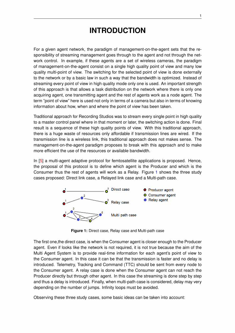
In [5] a multi-agent adaptive protocol for femtosatellite applications is proposed. Hence,the proposal of this protocol is to define which agent is the Producer and which is theConsumer thus the rest of agents will work as a Relay. Figure 1 shows the three studycases proposed: Direct link case, a Relayed link case and a Multi-path case.
Figure 1: Direct case, Relay case and Multi-path case
The first one,the direct case, is when the Consumer agent is closer enough to the Produceragent. Even if looks like the network is not required, it is not true because the aim of theMulti Agent System is to provide real-time information for each agent’s point of view tothe Consumer agent. In this case it can be that the transmission is faster and no delay isintroduced. Telemetry, Tracking and Command (TTC) should be sent from every node tothe Consumer agent. A relay case is done when the Consumer agent can not reach theProducer directly but through other agent. In this case the streaming is done step by stepand thus a delay is introduced. Finally, when multi-path case is considered, delay may verydepending on the number of jumps. Infinity loops must be avoided.
Observing these three study cases, some basic ideas can be taken into account:
2 A multi-agent payload management approach for femtosatellite applications
TTC information of all nodes should be sent whatever the configuration is.
The smaller jump number is, the better.
In multi-path case, lower jump number is preferred.
Need to avoid infinite loops.
Need to ignore repeated information.
The WikiSat space program consists on implementing a low cost satellite for the N-Prize.
The satellite WikiSat is a less than 20 grams femtosatellite that will be the brain of themission, it is responsible of ignite the rocket, its control, ignite the Stage 2, etc. Thesecapabilities save job and weight because there is no need of a single control system forthe rocket, the WikiSat is capable of doing these functions by itself.
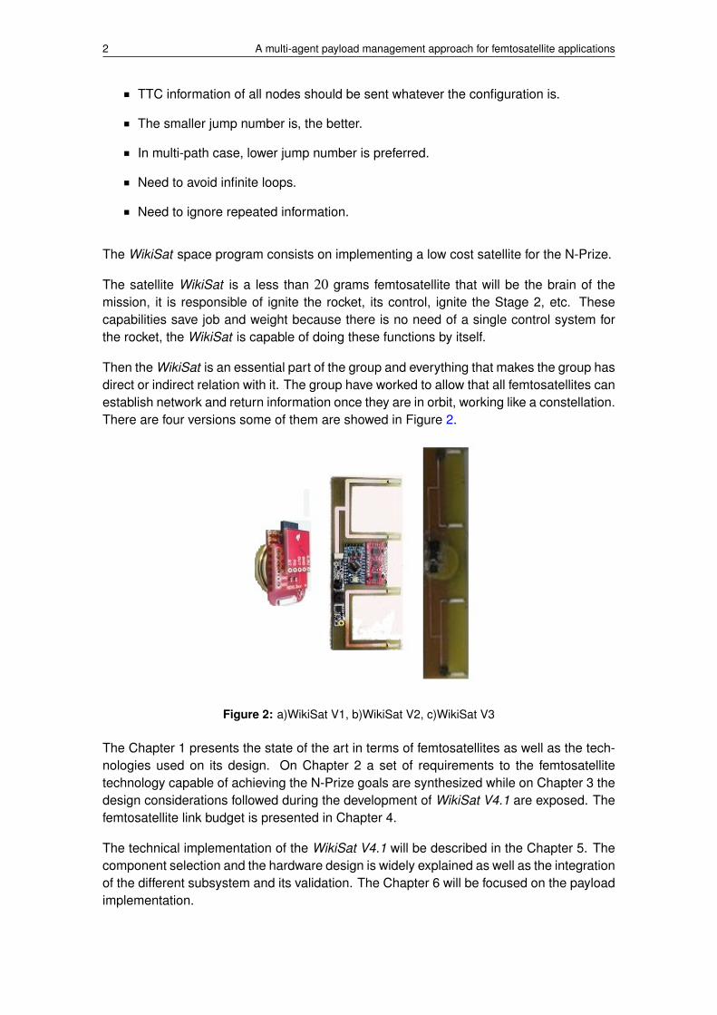
Then the WikiSat is an essential part of the group and everything that makes the group hasdirect or indirect relation with it. The group have worked to allow that all femtosatellites canestablish network and return information once they are in orbit, working like a constellation.There are four versions some of them are showed in Figure 2.
Figure 2: a)WikiSat V1, b)WikiSat V2, c)WikiSat V3
The Chapter 1 presents the state of the art in terms of femtosatellites as well as the tech-nologies used on its design. On Chapter 2 a set of requirements to the femtosatellitetechnology capable of achieving the N-Prize goals are synthesized while on Chapter 3 thedesign considerations followed during the development of WikiSat V4.1 are exposed. Thefemtosatellite link budget is presented in Chapter 4.
The technical implementation of the WikiSat V4.1 will be described in the Chapter 5. Thecomponent selection and the hardware design is widely explained as well as the integrationof the different subsystem and its validation. The Chapter 6 will be focused on the payloadimplementation.

3
As the concept of the paradigm of management-on-the-agent was developed enough in[5] this work will be focused on the development of an agent that follows this paradigm.

4 A multi-agent payload management approach for femtosatellite applications
RELATED WORK 5
CHAPTER 1. RELATED WORK
1.1. Satellite classification
In general, a satellite is any object that orbits something else, as, for example, the Moonorbits the Earth. An artificial satellite is a device which has been placed into orbit by humanendeavor.
First artificial satellite (Sputnik 1) was launched by the Soviet Union in the latest 1950s.Since then, thousands of satellites1 have been launched into orbit around the Earth; alsosome satellites, notably space stations, have been launched in parts and assembled inorbit.
Different purposes can be developed by satellites. Common types include military and civil-ian Earth observation, communications, navigation, weather and research. Space stationsand human spacecraft in orbit are also satellites. Satellite orbits vary greatly, dependingon its purpose and are classified in a number of ways. Well-known (overlapping) classesinclude low Earth orbit, polar orbit, and geostationary orbit.
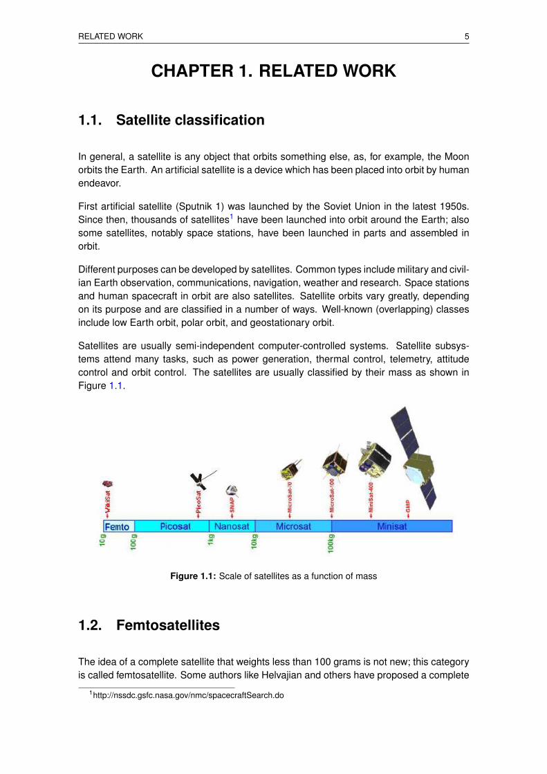
Satellites are usually semi-independent computer-controlled systems. Satellite subsys-tems attend many tasks, such as power generation, thermal control, telemetry, attitudecontrol and orbit control. The satellites are usually classified by their mass as shown inFigure 1.1.
Figure 1.1: Scale of satellites as a function of mass
1.2. Femtosatellites
The idea of a complete satellite that weights less than 100 grams is not new; this categoryis called femtosatellite. Some authors like Helvajian and others have proposed a complete
1http://nssdc.gsfc.nasa.gov/nmc/spacecraftSearch.do
6 A multi-agent payload management approach for femtosatellite applications
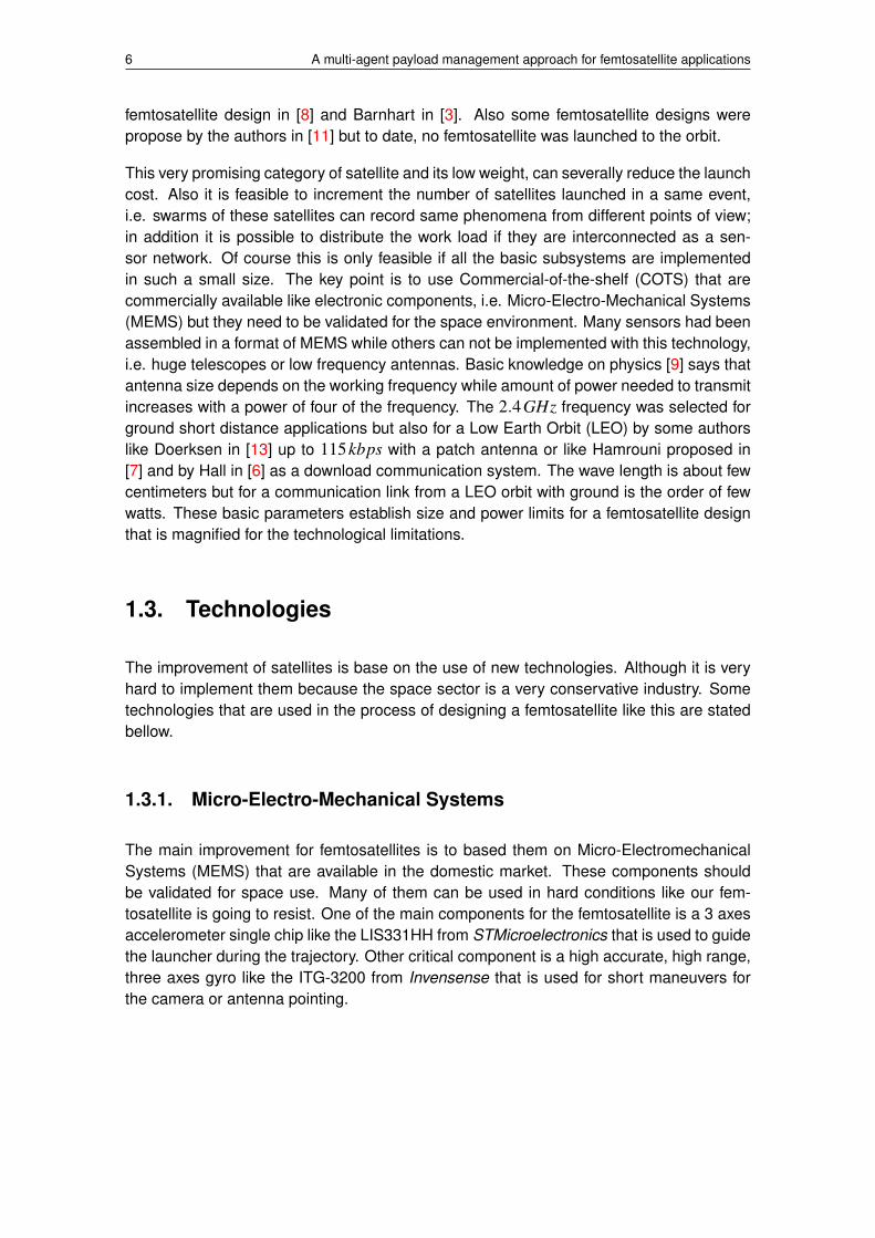
femtosatellite design in [8] and Barnhart in [3]. Also some femtosatellite designs werepropose by the authors in [11] but to date, no femtosatellite was launched to the orbit.
This very promising category of satellite and its low weight, can severally reduce the launchcost. Also it is feasible to increment the number of satellites launched in a same event,i.e. swarms of these satellites can record same phenomena from different points of view;in addition it is possible to distribute the work load if they are interconnected as a sen-sor network. Of course this is only feasible if all the basic subsystems are implementedin such a small size. The key point is to use Commercial-of-the-shelf (COTS) that arecommercially available like electronic components, i.e. Micro-Electro-Mechanical Systems(MEMS) but they need to be validated for the space environment. Many sensors had beenassembled in a format of MEMS while others can not be implemented with this technology,i.e. huge telescopes or low frequency antennas. Basic knowledge on physics [9] says thatantenna size depends on the working frequency while amount of power needed to transmitincreases with a power of four of the frequency. The 2.4GHz frequency was selected forground short distance applications but also for a Low Earth Orbit (LEO) by some authorslike Doerksen in [13] up to 115kbps with a patch antenna or like Hamrouni proposed in[7] and by Hall in [6] as a download communication system. The wave length is about fewcentimeters but for a communication link from a LEO orbit with ground is the order of fewwatts. These basic parameters establish size and power limits for a femtosatellite designthat is magnified for the technological limitations.
1.3. Technologies
The improvement of satellites is base on the use of new technologies. Although it is veryhard to implement them because the space sector is a very conservative industry. Sometechnologies that are used in the process of designing a femtosatellite like this are statedbellow.
1.3.1. Micro-Electro-Mechanical Systems
The main improvement for femtosatellites is to based them on Micro-ElectromechanicalSystems (MEMS) that are available in the domestic market. These components shouldbe validated for space use. Many of them can be used in hard conditions like our fem-tosatellite is going to resist. One of the main components for the femtosatellite is a 3 axesaccelerometer single chip like the LIS331HH from STMicroelectronics that is used to guidethe launcher during the trajectory. Other critical component is a high accurate, high range,three axes gyro like the ITG-3200 from Invensense that is used for short maneuvers forthe camera or antenna pointing.
RELATED WORK 7
1.3.2. Printed Circuit Boards
The use of Printed Circuit Board (PCB) makes the design and implementation very easyand cheap. This technology is nowadays, very well expanded. It is feasible to designwith open tools the whole satellite and for less that 100ea manufacturer will build andassemble your design in only few days. Additionally, the use of micro-strips allows todesign and implement in the same platform many kinds of High Gain Antennas (HGA)using a technology of micro ceramic antennas array.
1.3.3. Surface Mount Devices Technology
Based on PCB, the use of Surface Mount Device (SMD) is another improvement in termsof weight saving, size reduction, high shock resistant and robustness. For the femtosatel-lite development we are interested in the use of these devices because they are easyto assemble during the re-flow. Many electronic components are available in this format,including a complete high definition camera.
1.3.4. CameraCube
CameraCube is a technology that integrates a whole camera (sensor, circuit and lens)inside a cube able to re-flow in a PCB. There is a new growing market in this sens for phonemobiles and i-Pod applications. A good example of this is a high definition camera VW6754from STMicroelectronics that has 5x5x4mm and 1,600x1,200 pixels. These cameras usea technology called wafer, a pin matrix is below the camera with bubbles. When hightemperature is applied, these bubbles made of soldering past melt and welds the camerain the PCB. The level of integration is really high.
1.3.5. Inter-Integrated Circuit Bus
The I2C bus or IIC stands for Inter-Integrated Circuit that is used to attach low-speedperipherals to a Main Control Unit (MCU). Many sensors are based on an Analog to Dig-ital Converter (ADC) that is inside the sensor itself and data is provided in digital formatthrough the I2C bus. Two wires are only required to connect all the sensor in the fem-tosatellite. This fact results in a reduction in complexity and space saving in the PCB.Additionally, no calibrations or maintenance are required. The speed of this bus reachesup to 100 kbits per second so this bus is not suitable for the payload data streaming butfor the payload control. In our case, the femtosatellite will have a dedicated streaming busdirect from the serializer to the transceiver.

8 A multi-agent payload management approach for femtosatellite applications
REQUIREMENTS 9
CHAPTER 2. REQUIREMENTS
2.1. Architecture
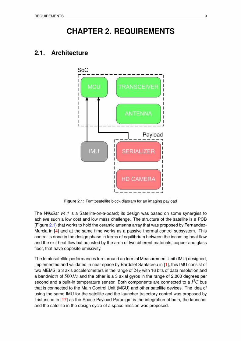
Figure 2.1: Femtosatellite block diagram for an imaging payload
The WikiSat V4.1 is a Satellite-on-a-board; its design was based on some synergies toachieve such a low cost and low mass challenge. The structure of the satellite is a PCB(Figure 2.1) that works to hold the ceramic antenna array that was proposed by Fernandez-Murcia in [4] and at the same time works as a passive thermal control subsystem. Thiscontrol is done in the design phase in terms of equilibrium between the incoming heat flowand the exit heat flow but adjusted by the area of two different materials, copper and glassfiber, that have opposite emissivity.
The femtosatellite performances turn around an Inertial Measurement Unit (IMU) designed,implemented and validated in near space by Bardolet Santacreu in [1], this IMU consist oftwo MEMS: a 3 axis accelerometers in the range of 24g with 16 bits of data resolution anda bandwidth of 500Hz and the other is a 3 axial gyros in the range of 2,000 degrees persecond and a built-in temperature sensor. Both components are connected to a I2C busthat is connected to the Main Control Unit (MCU) and other satellite devices. The idea ofusing the same IMU for the satellite and the launcher trajectory control was proposed byTristancho in [17] as the Space Payload Paradigm is the integration of both, the launcherand the satellite in the design cycle of a space mission was proposed.
10 A multi-agent payload management approach for femtosatellite applications
The satellite attitude control and the launcher vector control was studied by Navarro-Morcillo in [14] having the same inputs but different output. In order to reduce 10 timesthe launcher size, a balloon launching ramp was proposed by Bonet-Osorio in [2]. Whena launch is done at an altitude of 35 kilometers; all the hard atmosphere and hazards areavoided and a large quantity of propellant is saved, hence safer and more often launchescan be done weekly.
2.2. System requirements
In this section the mission requirements, as well as the femtosatellite ones, are presented.The WikiSat organization is the one in charge of the development and implementation ofthe femtosatellite. This organization has implemented on its designs the following direc-tives and policies respect to it:
Simplicity directive. The KISS rule stands for Keep It Simple and Safe.
Absolute minimum directive, closer tolerances and a design only for its mission.
No redundancy policy. Single fault tolerant system.
Preferred configuration. Complete capabilities in the default configuration.
The system requirements are the following:
S0: The femtosatellite, as a system, shall stay in Low Earth Orbit for at least one week inorder to allow the payload purpose before the end of this Master Thesis.
S1: The vector of the launcher used to launch the femtosatellite will be controlled by itself.The mini-launcher should have two stages and the bill of materials must be lowerthan 1.000£, the femtosatellite is not included in this price.
S2: The femtosatellite should be operated by a development platform and the Earth con-trol must be open source in order to guarantee the platform transparency.
2.3. High level requirements
HL00: The Power Supply subsystem shall provide electrical power for the computing ofthe orbit and the tracking.
HL01: The Communication subsystem shall transmit and receive the tracking and payloadinformation.
HL02: The Structure subsystem shall be used protect the femtosatellite components andbe used as a thermal path for thermal loads.

REQUIREMENTS 11
HL03: The Attitude determination subsystem shall determine the attitude by inertial meansand be helped by optic sensors.
HL04: The Position determination subsystem shall determine the position in the orbit byinertial mean and be helped by optic sensors.
HL05: The Attitude control subsystem shall point the high gain antenna to the Earth in apassive way using the Earth’s magnetic field.
HL06: The Tracking subsystem shall transmit its computed position to a ground stationonly when passing over the ground station’s sky.
HL07: The Video recording subsystem shall record pictures and video if required.
2.4. Low level requirements
LL000: The battery shall provide enough power for the whole mission at any time and inpeak power conditions for a limited period of time.
LL001: The electrical power subsystem shall be used in short periods of time having anidle model.
LL010: The ground communication link shall be disconnected when the ground electricalpower source is not available.
LL011: The ground monitoring function shall be disconnected when the ground electricalpower source is not available.
LL012: The downlink subsystem shall transmit the monitoring information from the fem-tosatellite to the ground station before the launch and using the low gain antenna.
LL013: The uplink subsystem shall receive the configuration information form the groundstation to the femtosatellite before the launch and using the low gain antenna.
LL020: The structure shall have a high thermal inertia in order to be used as the thermalcontrol.
LL021: The structure subsystem shall support physical loads up to 500G.
LL022: The structure subsystem shall work in a temperature range from -150 to 250◦C.
LL023: The structure subsystem shall have a surface with cooling properties in order toe a good heat flow in such a way that the resulting temperature remains inside therange between -40 to 60◦C.
LL030: The attitude determination subsystem shall be calculated from two different sources(optical devices and gyros).
LL040: The position determination subsystem shall be calculated from two different sources(optical devices and accelerometers).

12 A multi-agent payload management approach for femtosatellite applications
LL041: The position determination subsystem shall guarantee an error less than one de-gree in latitude and one degree in longitude and the sum of both has to be an arealess than 10,000 square kilometers.
LL050: The attitude control subsystem shall point the high gain antenna towards theground with an angular accuracy of 5 degrees.
LL051: The attitude control subsystem shall absorb any rotation energy produced by theradiation pressure wind in less than few minutes.
LL060: The tracking subsystem shall transmit the femtosatellite computed position at leastonce to every ground station in the list of available ground stations.
LL070: The Video recording subsystem shall take pictures with a resolution of at least1,280 horizontal by 1,024 vertical.
LL071: The Video recording subsystem shall take videos with a frame rate of 15 framesper second at least.
LL072: The Video recording subsystem shall have the possibility of compressing picturesand videos using a JPEG compression.
2.5. Additional requirements
Operational Requirements
AD000: The femtosatellite shall be able to receive the launch position in order to align theinertial Measurement Unit before launch.
Safety Requirements
AD001: The femtosatellite battery shall be only used when the femtosatellite is deployed.
Performance Requirements
AD002: The tracking subsystem shall be able to illuminate an area of 200 kilometers indiameter.
Physical and Installation Requirements
AD003: The femtosatellite size shall be lower than 0.2 meters in any direction.
Maintainability Requirements

REQUIREMENTS 13
AD004: The femtosatellite shall be able to keep ready to launch at least for two yearswithout any maintenance action.
Interference Requirements
AD005: The femtosatellite shall be electromagnetically compatible with the mini-launcher.

14 A multi-agent payload management approach for femtosatellite applications

DESIGN CONSIDERATIONS 15
CHAPTER 3. DESIGN CONSIDERATIONS
The scope of this chapter is to justify how to reduce launch costs based on the list pub-lished in [10] by James R. Wertz. This list contains the major trends in the space industryin the US that are:
Decreasing cost of basic electronics.
Increased capability of software due to more capable, faster processes.
Increasing performance capability of electronic packages of a specific size.
Increasing capability of mission-related software.
Increasing reliability of basic components.
Increased use of advanced composite technology to reduce structural masses.
Increased use of computer technology for decreasing staffing requirements for launchday operations.
Motivation to use commercial launch providers whenever possible for governmentprojects as well as for commercial projects.
Increasing political pressure to separate NASA from launch services.
Establishment of private spaceports to compete with federal ranges.
Severe budgetary pressure on federal discretionary spending.
The trends outlined above result in decreased size and mass of payloads. Because of thisresultant trend, launch cost per unit mass of payload becomes less important than totallaunch cost for dedicated missions as the last stage becomes the most massive part ofthe orbited mass. Decreased mass of specific payload packages and the availability ofexcess payload mass in existing specific launch vehicle configurations drive a tendency tomanifest multiple payloads on a given launcher. This makes necessary the existence ofsome regulations. Current technological, economic and regulatory realities forbid payloaddelivery to LEO for true costs of less than about $2,000 /kg.
One of the successful strategies employed by Arianespace and explained by Mowry in [16]is to make multiple rockets, with different payload interfacing, at one time. This strategy, notonly allows to obtain greater probability of launch success, it also maximizes the potentialfor some cost reductions.
3.1. Documentation program
For the development of this project, a documentation program based on five documentshas been created: ConOps document, System requirements document, System design
16 A multi-agent payload management approach for femtosatellite applications
document, Program management plan and Engineering management plan that are sum-marized following:
WikiSat ConOps Document contains the information related to the utility of the system.This document contains the user manual and is used by clients.
WikiSat System Requirements Document contains the list of requirements that the sys-tem shall meet. This document is used by engineers to develop the detailed subsys-tem document.
WikiSat System Design Document contains the definition of components required foreach subsystem. This document is used by engineers to build the system.
WikiSat Program Management Plan contains the planning to build and operate the sys-tem. This document is used by engineers to design the mission and by the operator.
WikiSat Engineering Management Plan contains information about the role of each en-gineer in the organization. This document is used by the organization manager.
3.2. Mechanical considerations
The aerospace science is, by definition, a very demanding sector. One of the challengesof this project is to fit all the aforementioned subsystems in a mass budget of less than20 grams. Additionally, the femtosatellite should support accelerations up to 500g (About4,900m/s2), there is no extra mass for reinforcement. The structure itself must be amonolithic block. The key point is the use of two advanced technologies: PCB and SMD.Printed Circuit Board is a very well known technology that make easy the integration of allthe components in a single layer of fiberglass. The Surface Mounted Devices are re-flowedover the copper layers of the PCB and they can resist high loads thanks to the lightnessof the components. Extra hardware, like struts or bolts, is not required to increase thetoughness. This fact makes the femtosatellite design very light and easy to assemble. ThePCB has good dielectric properties and also can be used for thermal control.
3.3. Thermal considerations
There is a heat flow of income heat and outcome heat. The heat flow received by thefemtosatellite is determined by the Equation 3.1 and the heat emitted by the femtosatelliteis determined by the Equation 3.2; where α is intensity, I is the absorbency, F is thegeometric factor, A is the effective area, σ is the Boltzmann constant of 5.67 ·10−8W/(m2 ·K4), T is the effective temperature and ε is the emissivity.
Qin = α · I ·F ·A (3.1)
DESIGN CONSIDERATIONS 17
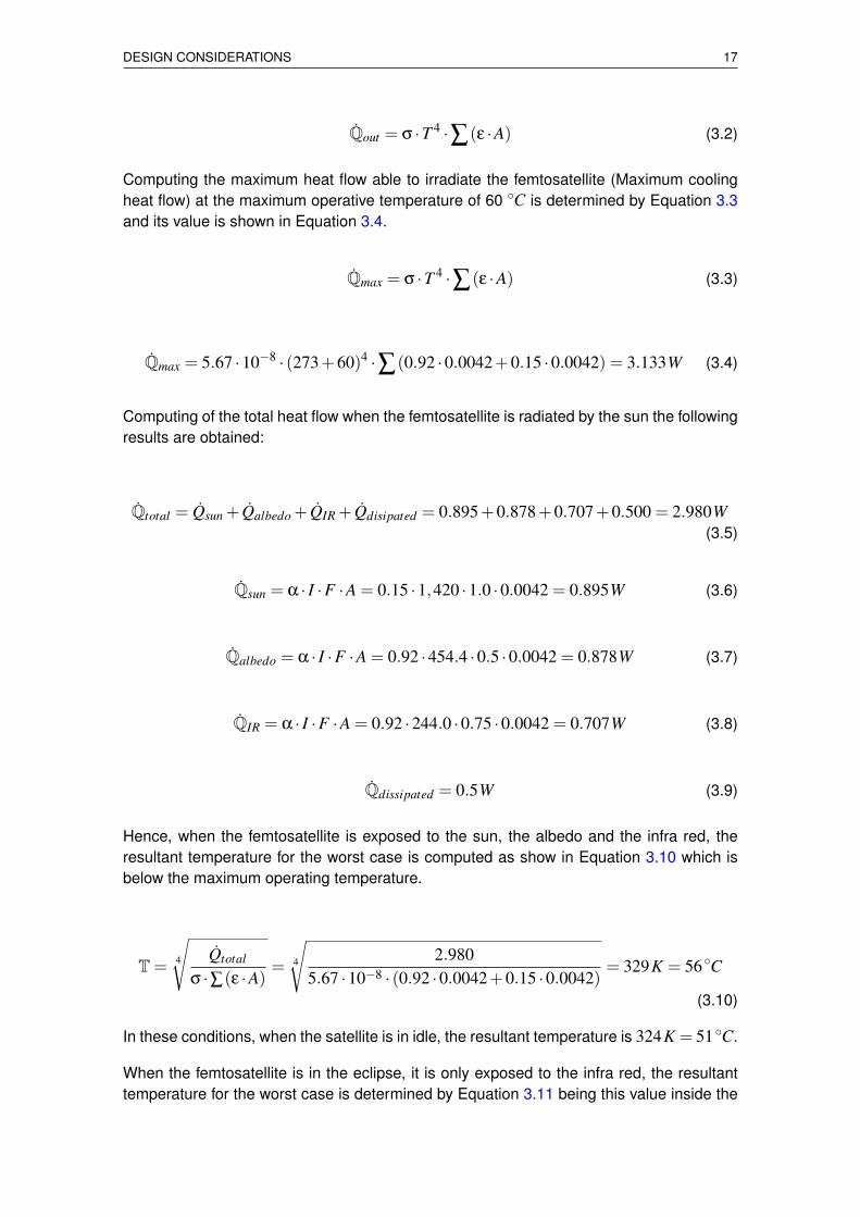
Qout = σ ·T 4 ·∑(ε ·A) (3.2)
Computing the maximum heat flow able to irradiate the femtosatellite (Maximum coolingheat flow) at the maximum operative temperature of 60 ◦C is determined by Equation 3.3and its value is shown in Equation 3.4.
Qmax = σ ·T 4 ·∑(ε ·A) (3.3)
Qmax = 5.67 ·10−8 · (273+60)4 ·∑(0.92 ·0.0042+0.15 ·0.0042) = 3.133W (3.4)
Computing of the total heat flow when the femtosatellite is radiated by the sun the followingresults are obtained:
Qtotal = Qsun + Qalbedo + QIR + Qdisipated = 0.895+0.878+0.707+0.500 = 2.980W(3.5)
Qsun = α · I ·F ·A = 0.15 ·1,420 ·1.0 ·0.0042 = 0.895W (3.6)
Qalbedo = α · I ·F ·A = 0.92 ·454.4 ·0.5 ·0.0042 = 0.878W (3.7)
QIR = α · I ·F ·A = 0.92 ·244.0 ·0.75 ·0.0042 = 0.707W (3.8)
Qdissipated = 0.5W (3.9)
Hence, when the femtosatellite is exposed to the sun, the albedo and the infra red, theresultant temperature for the worst case is computed as show in Equation 3.10 which isbelow the maximum operating temperature.
T= 4
√Qtotal
σ ·∑(ε ·A)= 4
√2.980
5.67 ·10−8 · (0.92 ·0.0042+0.15 ·0.0042)= 329K = 56◦C
(3.10)
In these conditions, when the satellite is in idle, the resultant temperature is 324K = 51◦C.
When the femtosatellite is in the eclipse, it is only exposed to the infra red, the resultanttemperature for the worst case is determined by Equation 3.11 being this value inside the
18 A multi-agent payload management approach for femtosatellite applications
operating temperature range. In these same conditions, when the satellite is in idle, theresultant temperature is 253K =−20◦C.
T= 4
√Qtotal
σ ·∑(ε ·A)= 4
√1.044
5.67 ·10−8 · (0.92 ·0.0042+0.15 ·0.0042)= 253K =−20◦C
(3.11)
3.3.1. Thermal design discussion
This is a passive thermal control subsystem because the femtosatellite has a good bal-ance between the income heat flow and the outcome heat flow. Any modification in theinitial design may vary the working temperature range. In this case the copper area in thePCB back layer should be changed until the femtosatellite temperature range is correct.The copper has a good emissivity property while the fiberglass has a very bad emissivityproperty. If the PCB back layer has to much copper, the femtosatellite can irradiate theheat and the femtosatellite tends to cool down. Opposite, if the predominant area in thePCB back plate layer is fiberglass, the femtosatellite tends to keep the heat and it warmsup.
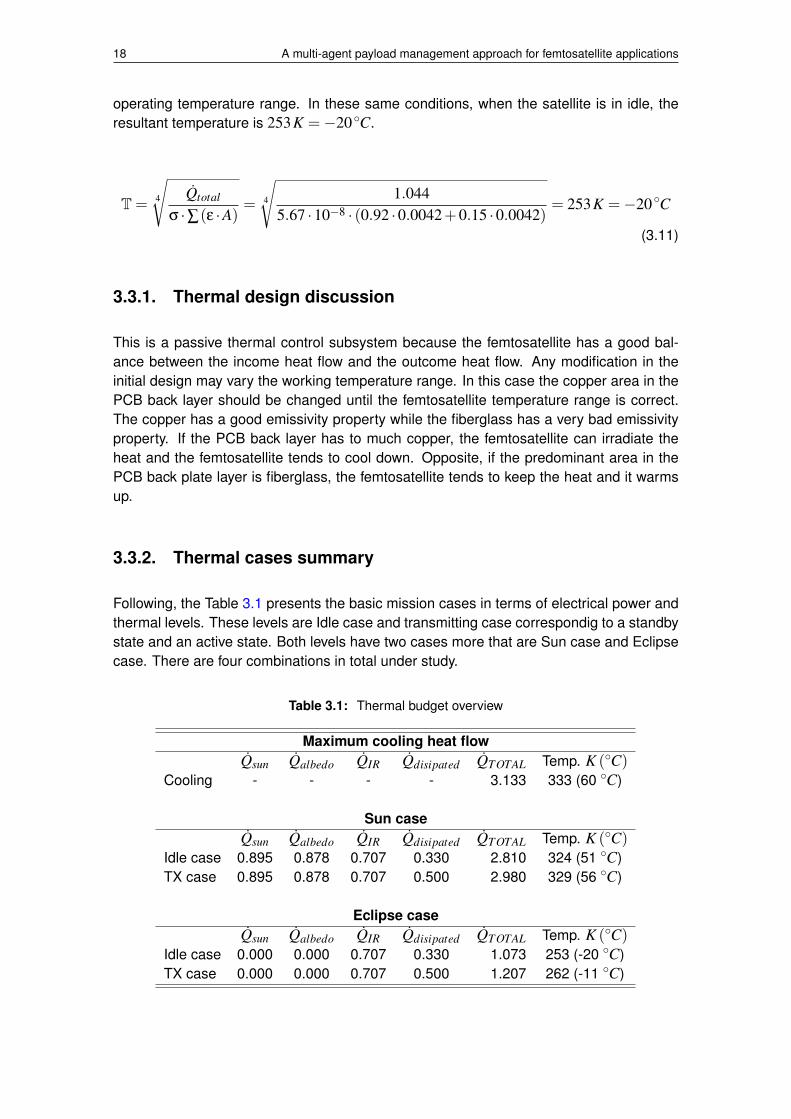
3.3.2. Thermal cases summary
Following, the Table 3.1 presents the basic mission cases in terms of electrical power andthermal levels. These levels are Idle case and transmitting case correspondig to a standbystate and an active state. Both levels have two cases more that are Sun case and Eclipsecase. There are four combinations in total under study.
Table 3.1: Thermal budget overview
Maximum cooling heat flowQsun Qalbedo QIR Qdisipated QTOTAL Temp. K (◦C)
Cooling - - - - 3.133 333 (60 ◦C)
Sun caseQsun Qalbedo QIR Qdisipated QTOTAL Temp. K (◦C)
Idle case 0.895 0.878 0.707 0.330 2.810 324 (51 ◦C)TX case 0.895 0.878 0.707 0.500 2.980 329 (56 ◦C)
Eclipse caseQsun Qalbedo QIR Qdisipated QTOTAL Temp. K (◦C)
Idle case 0.000 0.000 0.707 0.330 1.073 253 (-20 ◦C)TX case 0.000 0.000 0.707 0.500 1.207 262 (-11 ◦C)
DESIGN CONSIDERATIONS 19
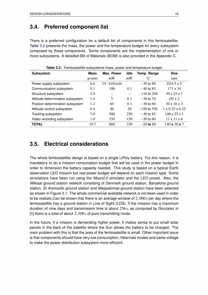
3.4. Preferred component list
There is a preferred configuration for a default list of components in this femtosatellite.Table 3.2 presents the mass, the power and the temperature budget for every subsystemcomposed by these components. Some components are the implementation of one ormore subsystems. A detailled Bill of Materials (BOM) is also provided in the Appendix C.
Table 3.2: Femtosatellite subsystems mass, power and temperature budget
Subsystem Mass Max. Power Idle Temp. Range Sizegrams mW mW ◦C mm
Power supply subsystem 6.6 3V , 610mAh −30 to 60 D24.5 x 5Communication subsystem 0.1 100 0.1 −40 to 85 171 x 34Structure subsystem 2.0 − − −116 to 204 30 x 25 x 7Attitude determination subsystem 1.4 5 0.1 −30 to 70 D5 x 2Position determination subsystem 1.2 65 0.1 −30 to 60 30 x 16 x 3Attitude control subsystem 0.4 40 30 −150 to 550 1 x 0.25 x 0.25Tracking subsystem 7.0 500 250 −40 to 85 140 x 25 x 1Video recording subsystem 1.0 150 150 −20 to 60 11 x 11 x 6TOTAL 19.7 860 330 −20 to 60 140 x 30 x 7
3.5. Electrical considerations
The whole femtosatellite design is based on a single LiPoly battery. For this reason, it ismandatory to do a mission consumption budget that will be used in the power budget inorder to dimension the battery capacity needed. This study is based on a typical Earthobservation LEO mission but real power budget will depend on each mission type. Somesimulations have been run using the Moon2.0 simulator and the LEO preset. Also, theWikisat ground station network consisting of Denmark ground station, Barcelona groundstation, El Arenosillo ground station and Maspalomas ground station have been selectedas shown in Figure 3.1. The whole commercial available network is not been used in orderto be realistic.Can be shown that there is an average window of 2,000s per day where thefemtosatellite has a ground station in Line of Sight (LOS). If the mission has a maximumduration of nine days and transmission time is about 256s, as computed by Gonzalez in[5] there is a total of about 2,300s of pure transmitting mode.
In the future, if a mission is demanding higher power, it makes sense to put small solarpanels in the back of the satellite where the Sun allows the battery to be charged. Themain problem with this is that the area of the femtosatellite is small. Other important issueis that components should have very low consumption, hibernate modes and same voltageto make the power distribution subsystem more efficient.

20 A multi-agent payload management approach for femtosatellite applications
Figure 3.1: Wikisat ground station network and femto-satellite trajectory. (Green available)
3.5.1. Power budget
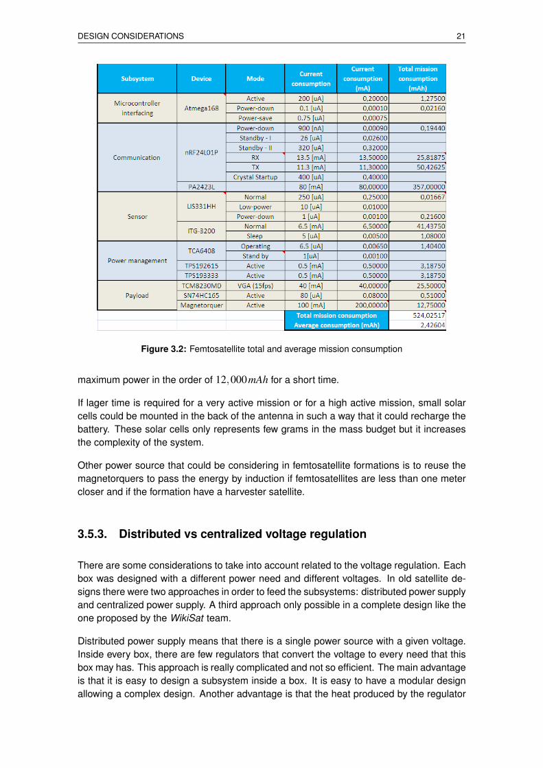
There are two working modes: Standby and Active. When Standby mode, also calledIdle case, no main work is done by the satellite except for the integration of the attitudean time counter. When Active mode, also called transmitting case, all the subsystemsare actives. Magnetorquers could generate a magnetic field in order to have an attitudecontrol to point the high gain antenna towards the ground station or to follow an interestingpoint for the payload. The transceiver and the power amplifier could transmitt or receiveinformation. Since this femtosatellite uses a batery, all the available power should be usedonly when necessary. The total mission time when the satellite could stay in active modeduring these nine days are about 382 minutes of a total of about 13,000 minutes. Only 3percent of the mission time, the femtosatellite will have an important battery leak. The totalmission consumption is about 520mAh and the total available is 610mAh. We have to sayhere that this is only a simulation based on a typical mission. Accurate budget should bedone in a future real mission. Finally, the average consumption per hour is 2.4mAh
Table 3.2 is a summary about the femtosatellite main component consumptions. Someasumptions were done related to the Active mode. Transmittion will take only 70 percentand Reception is the other 30 percent. Pictures are taken only during 10 percent of theActive time meanwhile the attitude control will take only 1 percent of this time. The highestcurrent consumption is due to the magnetorquer and the power amplifier but the poweramplifier is used lager time so this component represents the major consumption. For thisreason saving modes are recommended like the Burst technology or Data Compression.
3.5.2. Power sources
The power source for this kind of missions, due to the short mission time is strongly re-comended to use batteries. 34 percent of the mass budget is for the battery that represents6.6 grams compared to the tracking subsystem that is the 36 percent of the mass budgetin 7.0 grams. In the early designs, i.e. WikiSat v3 a coin batery was selected having abetter consumption to mass ration that the current LiPoly batteries. The main problem thata coin battery has is not the fact that it is no rechargeable but it has a very low maximumpower, about 50mAh, while the total consumption is 610mAh. LiPoly batteries have higher
DESIGN CONSIDERATIONS 21
Figure 3.2: Femtosatellite total and average mission consumption
maximum power in the order of 12,000mAh for a short time.
If lager time is required for a very active mission or for a high active mission, small solarcells could be mounted in the back of the antenna in such a way that it could recharge thebattery. These solar cells only represents few grams in the mass budget but it increasesthe complexity of the system.
Other power source that could be considering in femtosatellite formations is to reuse themagnetorquers to pass the energy by induction if femtosatellites are less than one metercloser and if the formation have a harvester satellite.
3.5.3. Distributed vs centralized voltage regulation
There are some considerations to take into account related to the voltage regulation. Eachbox was designed with a different power need and different voltages. In old satellite de-signs there were two approaches in order to feed the subsystems: distributed power supplyand centralized power supply. A third approach only possible in a complete design like theone proposed by the WikiSat team.
Distributed power supply means that there is a single power source with a given voltage.Inside every box, there are few regulators that convert the voltage to every need that thisbox may has. This approach is really complicated and not so efficient. The main advantageis that it is easy to design a subsystem inside a box. It is easy to have a modular designallowing a complex design. Another advantage is that the heat produced by the regulator
22 A multi-agent payload management approach for femtosatellite applications
is also distributed and is more efficient in terms of thermal distribution.
Centralized power supply has a single regulator for all the devices and for every voltage.The energy transformation is very efficient respect to the distributed approach. The designis really simple but no so modular. A good dimension in terms of power consumptionshould be done because it is not easy to isolate a box if this box has a problem.
Single power supply is a version of the centralized approach but, in this case, all thedevices have the same voltage and there is no need to convert to other voltages. This isthe most efficient design in terms of power transformation efficiency. The problem is thatthere is no way to do a modular design. All the system should be designed completelyfrom the scratch. This is the approach used in the WikiSat v4.1 except for the Payload thata centralized schema has been used. The rest of components will use 3.3V everywhere.This voltage has been chosen instead of 5.0V because the LiPoly battery has 3.7V andall the components are tolerant to it. There is no need to regulate the power except forsome cases like the transmitter that requires a very stable power source and, of course,the payload that has a different approach.
3.5.4. Cosmic radiation study and mitigation
The most important phase when designing a satellite is to study the cosmic radiation studyand its effects on the electronic parts. Radiation particles coming from solar wind, likeprotons and electrons, can be a serious problem for the semiconductor materials on board.In [15], a wide study of this effects on the WikiSat in presented. The key points extractedby Molas-Pous during her research are exposed bellow.
Short periods of radiation are allowed for a small satellites like this if they are in veryLow Earth Orbit (LEO)
The main radiation source apart of the Van Allen electrons and protons, is the socalled South Atlantic Anomaly (SAA) that is passing through it every day
The battery has a good shielding effect over the weak electronic components againstthe Single Events Effects (SEE) that can polarize a transistor or even destroy it.
3.6. Attitude determination and control subsystem
The attitude determination could be done by gyros but they have a lot of BIAS of drift errorand an absolute correction method is required. Gyros can provide a very accurate attitudedetermination value. In order to correct this BIAS, a magnetometer and a Sun-tracker willbe used. Accuracy is low in the order of 10 degrees while gyros can give an accuracy inthe order of 0.1 degrees.
The attitude control will be done by magnetorquers that are not really accurate but it is verysimple and easy to be assembled in the femtosatellite structure. These magnetorquers arecontrolled by the IO Expander with a current limit of 100mA per coil.
DESIGN CONSIDERATIONS 23
3.6.1. Earth magnetic field sensor
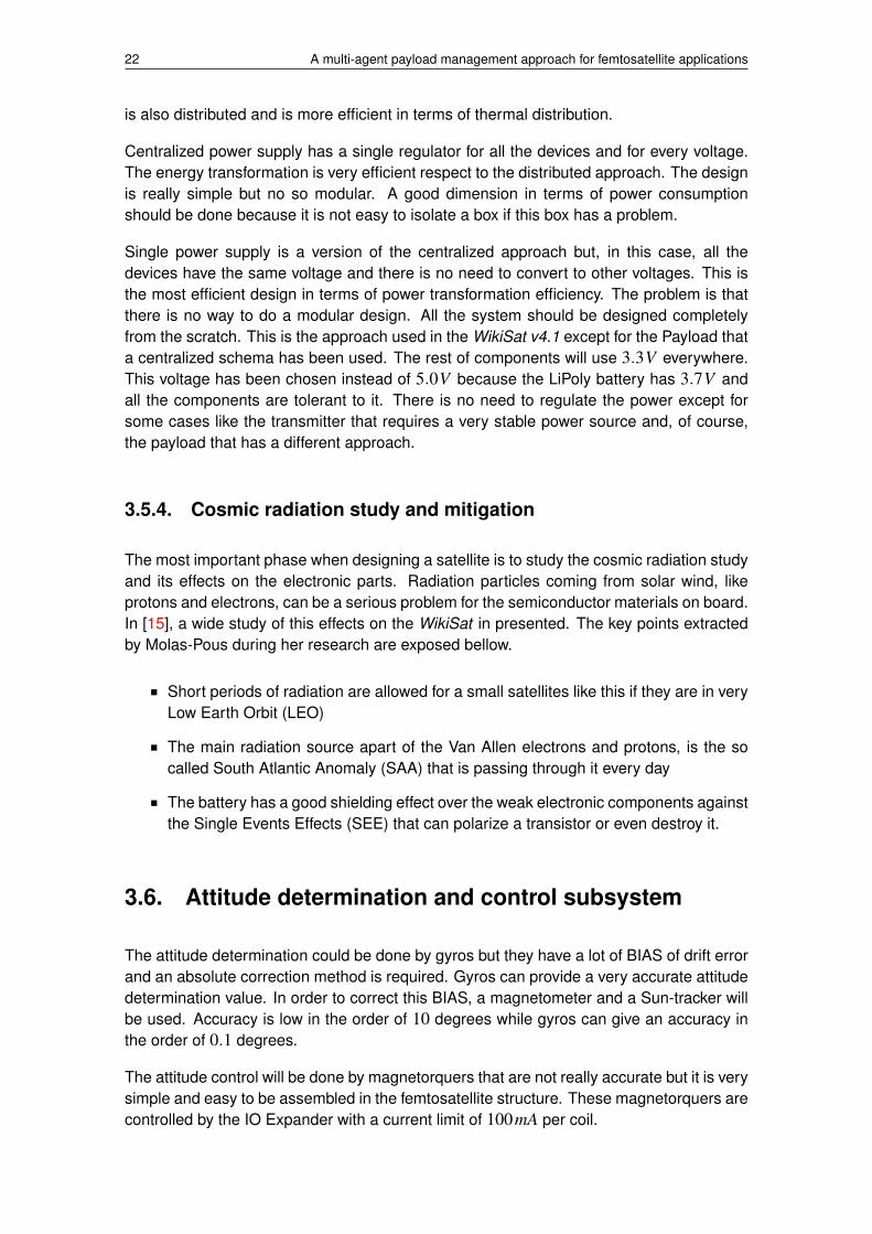
The attitude control is done by four magnetorquers. The control can be done in 2 degreesof freedom. These magnetorquers can generate a magnetic pole that reacts against theEarth magnetic field. The main problem with this technique is that we should know what isthe magnetic field surrounding the femtosatellite and the variations of the Earth’s magneticfield. WikiSat has a Earth’s magnetic field model in the EEPROM memory that is showedin figure 3.3 with information about the declination of the true magnetic North. There is anexample of implementation in the Appendix F. The magnetic model is based on the NOAAWorld Magnetic Model (National Oceanic and Atmospheric Administration). Comparingthe sensor reading with the value stored in the model, for a given coordinates, it is possibleto know one angle of the femtosatellite attitude. This method is useless in the poles due tothe gimbal lock effect.
Figure 3.3: Femtosatellite Earth’s magnetic field model and the NOAA real declination map
3.6.2. Sun-tracker sensor
We need to solve the other angle in order to know where the femtosatellite should pointwith the High Gain Antenna or the Payload Sensor. For this reason, a Sun-tracker shouldbe installed in the followinw WikiSat version. This other method is useless in the eclipsethat hapens every orbit. Additionally, it is possible to use the Moon if we know the positionnot only the Sun but the Moon. Typically, femtsatellite missions are more focused onday recording but download could be in any moment. Also, the main needs dor DisasterManagement are closer to the Equator.
3.7. Payload areas
Some rules about how to use the available payload areas are defined. In that way, thereis no need to worry about basic functionalities such as: COTS components conditioning,Logistics usage of COTS components, Tracking functionalities and Information downloadto Earth. Additionally, using these rules it make easier to test if the payload is going toaffect to the femtosatellite integrity.
The area of the femtosatellite WikiSat was optimized during the design. It was fitted to the
24 A multi-agent payload management approach for femtosatellite applications
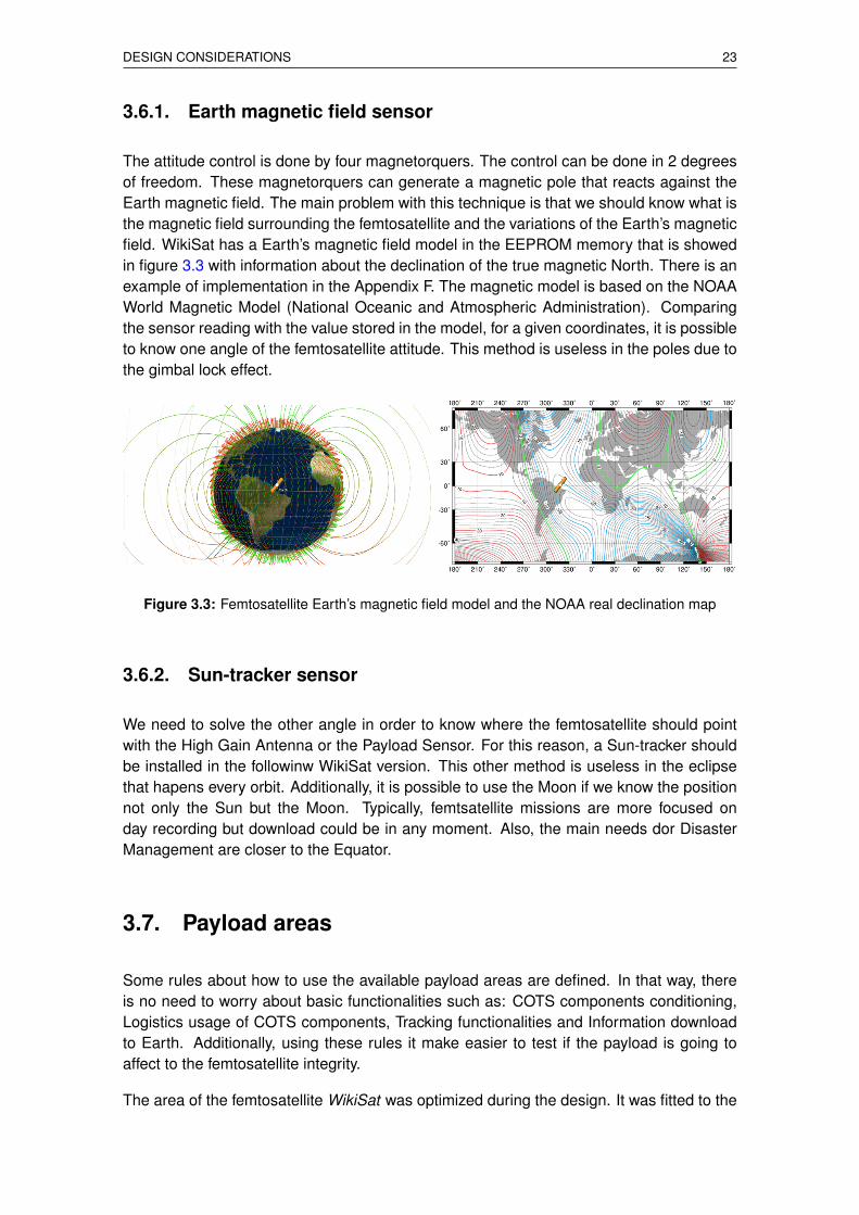
antenna array in order to reduce the size as much as possible. There are four differentzones clearly separated by the microstrips of the antenna. The most suitable part to allo-cate the circuitry, as show in Figure 3.4 is the central part because in the bottom part is thebattery protecting against radiation. It was decided to divide this area in two parts, one forthe femtosatellite and the other for the payload. The lateral areas is where the magnetor-quers are allocated leaving free space to use as payload if necessary. These lateral areashave two-fold problem: they are exposed to radiation and they need to be conditionedpassing lines through the microstrips. When lines are passed through the microstips it hasto be done in the bottom part of the satellite in order to no interfere the antenna. It is veryimportant to check that there is no near field interference in those passing points.
Figure 3.4: WikiSat V4.1 payload areas
3.7.1. PCB constraints
There are some constraints that should be taken into account when designing a PCB:
Lines can not be thinner tan 0.2mm and VIAS shall be at least of 0.6mm.
SMD components can not have a footprint lower than 0402 size (0.04×0.02 in,1.0×0.51 mm).
In case of needing more layers or SMD components with footprints lower than 0402size the implication on the manufacturing process will be studied.
Generally the ”8mil” (8µm) rules established on the micron-20.dru files of designrules for EAGLE PCB will be followed.
It is not allowed to pass through the microstrips in the bottom part cutting the copperground plane. If it is necessary to pass solder wires will be used.
It is not allowed to pass through the microstrips anyway only using a board with thesame characteristics and copper on the other side plus an EMC (Electromagneticcompatibility) study. In that case the same rules about passing lines in the bottompart are applied. Also, it will be necessary a study about electromagnetic interfer-ence with the synthetic aperture antenna and the magnetorquers and how can themetallic parts reflexions be and the harmonic generation of the transmitter payloadcomponents. It is not allowed to pass closer than 0.4mm from the microstrip.
It is desirable to have a ground plane closer to the microstrip, on the bottom and topsides.
DESIGN CONSIDERATIONS 25
It is allowed to mount PCB board above the other taking into account that this boardcan not exceed the payload area minus a 0.4mm border. It will be necessary to fixthem with resin and use pins to connect the buses, never connectors. The pile ofPCB boards never can exceed its area unless the previous rule is followed with itsimplications and limitations.
3.7.2. Main payload area use
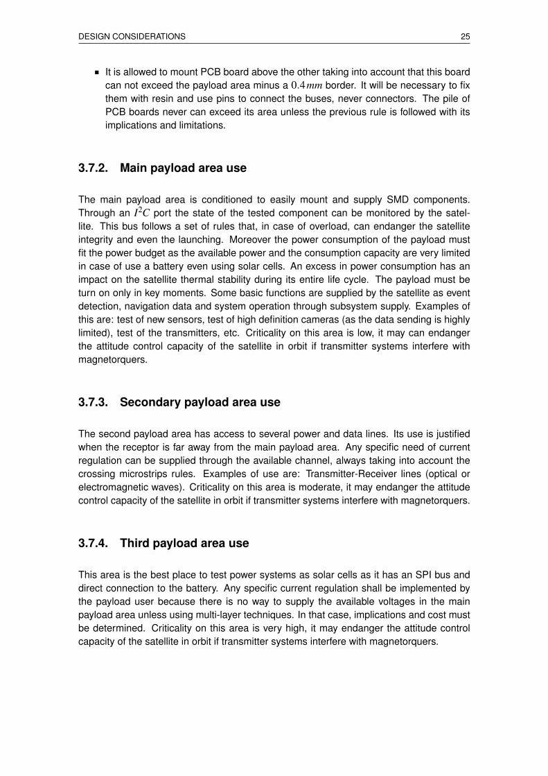
The main payload area is conditioned to easily mount and supply SMD components.Through an I2C port the state of the tested component can be monitored by the satel-lite. This bus follows a set of rules that, in case of overload, can endanger the satelliteintegrity and even the launching. Moreover the power consumption of the payload mustfit the power budget as the available power and the consumption capacity are very limitedin case of use a battery even using solar cells. An excess in power consumption has animpact on the satellite thermal stability during its entire life cycle. The payload must beturn on only in key moments. Some basic functions are supplied by the satellite as eventdetection, navigation data and system operation through subsystem supply. Examples ofthis are: test of new sensors, test of high definition cameras (as the data sending is highlylimited), test of the transmitters, etc. Criticality on this area is low, it may can endangerthe attitude control capacity of the satellite in orbit if transmitter systems interfere withmagnetorquers.
3.7.3. Secondary payload area use
The second payload area has access to several power and data lines. Its use is justifiedwhen the receptor is far away from the main payload area. Any specific need of currentregulation can be supplied through the available channel, always taking into account thecrossing microstrips rules. Examples of use are: Transmitter-Receiver lines (optical orelectromagnetic waves). Criticality on this area is moderate, it may endanger the attitudecontrol capacity of the satellite in orbit if transmitter systems interfere with magnetorquers.
3.7.4. Third payload area use
This area is the best place to test power systems as solar cells as it has an SPI bus anddirect connection to the battery. Any specific current regulation shall be implemented bythe payload user because there is no way to supply the available voltages in the mainpayload area unless using multi-layer techniques. In that case, implications and cost mustbe determined. Criticality on this area is very high, it may endanger the attitude controlcapacity of the satellite in orbit if transmitter systems interfere with magnetorquers.

26 A multi-agent payload management approach for femtosatellite applications
FEMTOSATELLITE LINK BUDGET 27
CHAPTER 4. FEMTOSATELLITE LINK BUDGET
The antenna design has been lead by Fernandez-Murcia and it is widely explained in [4].In this chapter only the main aspects are exposed.
4.1. Starting point
First of all, an accurate power link budget for the communication is necessary in order todetermine which elements will be required to increase the transceivers radio link (initiallydesigned for less than 100 meters). The maximum link distance is fixed at 500km, with aminimum of 250km and it will be unidirectional from the satellite to the base station. It willbe assembled on a Satellite-on-a-Board. It is selected the transceiver nRF24L01P [26] at2.4GHz System-on-Chip (SoC). It will work at 250kbps with a 0dBm power signal (GFSKmodulation).
The system must be upgradeable, ready to be updated with new elements constantly (step-design). It starts as a medium range communication system able to evolve to a long rangesystem. For this reason, some extra components like amplifiers (in both sides of the radiolink) are necessary to increase the range. It is mandatory to begin with the computation ofhow many extra gain (dB) will be necessary for the worst case condition (500 km). For thiscalculation, the following expression has been used:
Prx = Ptx +Gtx− etx−LFS−PLF +Grx− erx (4.1)
A polarization loss factor (PLF) of 3dB has been considered due to the different polariza-tion of the antennas, one linear and the other circular. This is critical because polarizationmay change due to satellite movement or any other undesired effect. A circular polariza-tion (20dB of gain) Yagi antenna is selected for reception and a 6dB antenna (the gainexpected for the array) for transmission is considered. Finally, 0.5dB losses due efficien-cies have been considered at each side of the link. The operating frequency ( f0) selectedis 2.49GHz, but it may change a bit if necessary (selecting a different operating channel).
Equation 4.1 can be easily transformed to estimate the extra gain necessary as shown inEquation 4.2.
Gextra = Ptx +Gtx− etx−LFS−PLF +Grx− erx−Prx,min = 50.3dB (4.2)
As noticed, at least 50.3dB gain is necessary, without considering noise effects, for a 500km link. Typical amplifiers offer between 10 and 20dB of gain, for this reason at least twoor three amplifiers will be required. In WikiSat V4.1 design there are one power amplifierand two low noise amplifiers.
28 A multi-agent payload management approach for femtosatellite applications
4.2. Design
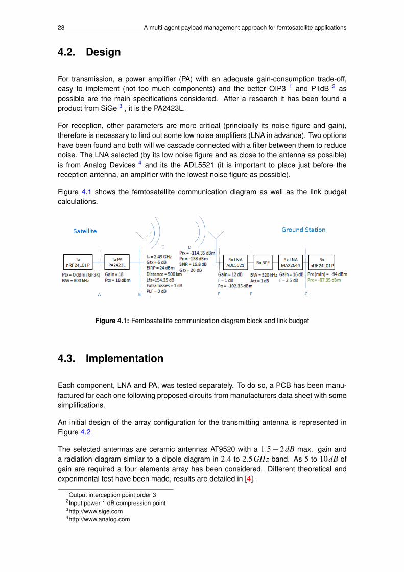
For transmission, a power amplifier (PA) with an adequate gain-consumption trade-off,easy to implement (not too much components) and the better OIP3 1 and P1dB 2 aspossible are the main specifications considered. After a research it has been found aproduct from SiGe 3 , it is the PA2423L.
For reception, other parameters are more critical (principally its noise figure and gain),therefore is necessary to find out some low noise amplifiers (LNA in advance). Two optionshave been found and both will we cascade connected with a filter between them to reducenoise. The LNA selected (by its low noise figure and as close to the antenna as possible)is from Analog Devices 4 and its the ADL5521 (it is important to place just before thereception antenna, an amplifier with the lowest noise figure as possible).
Figure 4.1 shows the femtosatellite communication diagram as well as the link budgetcalculations.
Figure 4.1: Femtosatellite communication diagram block and link budget
4.3. Implementation
Each component, LNA and PA, was tested separately. To do so, a PCB has been manu-factured for each one following proposed circuits from manufacturers data sheet with somesimplifications.
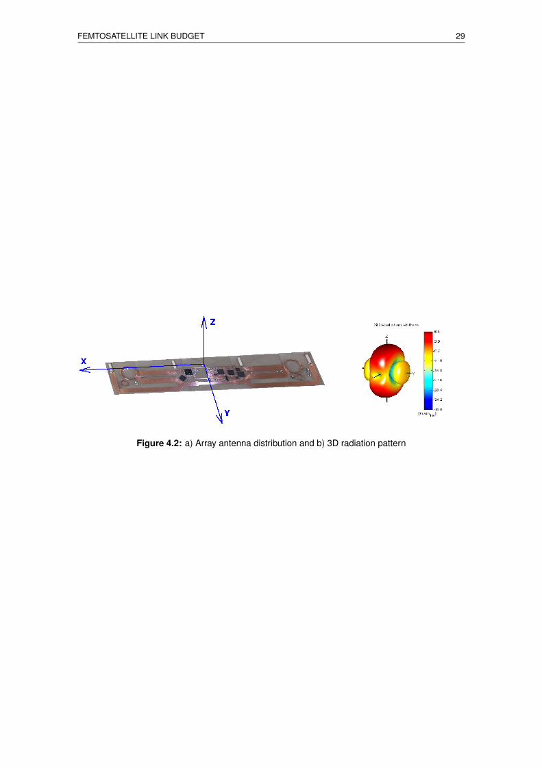
An initial design of the array configuration for the transmitting antenna is represented inFigure 4.2
The selected antennas are ceramic antennas AT9520 with a 1.5− 2dB max. gain anda radiation diagram similar to a dipole diagram in 2.4 to 2.5GHz band. As 5 to 10dB ofgain are required a four elements array has been considered. Different theoretical andexperimental test have been made, results are detailed in [4].
1Output interception point order 32Input power 1 dB compression point3http://www.sige.com4http://www.analog.com
FEMTOSATELLITE LINK BUDGET 29
Figure 4.2: a) Array antenna distribution and b) 3D radiation pattern

30 A multi-agent payload management approach for femtosatellite applications
SYSTEM IMPLEMENTATION 31
CHAPTER 5. SYSTEM IMPLEMENTATION
The technical implementation of the WikiSat v4.1 was split into the following parts: compo-nent selection, hardware design, prototyping, integration of the different subsystems andtest and validation of the whole system. The aforementioned implementation steps wereperformed and documented below. As mentioned before, one of the key aims of the tech-nical implementation part was to perform it with minimum expenses and using low-costin-house manufacturing tools that could be afforded by a particular hobbyist, open sourceand open hardware programming and debugging tools.
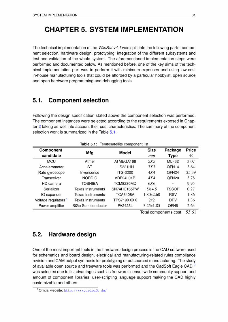
5.1. Component selection
Following the design specification stated above the component selection was performed.The component instances were selected according to the requirements exposed in Chap-ter 2 taking as well into account their cost characteristics. The summary of the componentselection work is summarized in the Table 5.1.
Table 5.1: Femtosatellite component list
ComponentMfg Model
Size Package Pricecandidate mm Type e
MCU Atmel ATMEGA168 5X5 MLF32 3.07Accelerometer ST LIS331HH 3X3 QFN14 3.64
Rate gyroscope Invensense ITG-3200 4X4 QFN24 25.39Transceiver NORDIC nRF24L01P 4X4 QFN20 3.78HD camera TOSHIBA TCM8230MD 6X6 - 9.95Serializer Texas Instruments SN74HC165PW 5X4.5 TSSOP 0.27
IO expander Texas Instruments TCA6408A 1.80x2.60 RSV 1.86Voltage regulators 1 Texas Instruments TPS719XXXX 2x2 DRV 1.36
Power amplifier SiGe Semiconductor PA2423L 3.25x1.85 QFN6 2.63
Total components cost 53.61
5.2. Hardware design
One of the most important tools in the hardware design process is the CAD software usedfor schematics and board design, electrical and manufacturing-related rules compliancerevision and CAM output synthesis for prototyping or outsourced manufacturing. The studyof available open source and freeware tools was performed and the CadSoft Eagle CAD 2
was selected due to its advantages such as freeware license; wide community support andamount of component libraries; user-scripting language support making the CAD highlycustomizable and others.
2Official website: http://www.cadsoft.de/
32 A multi-agent payload management approach for femtosatellite applications
This software package is able to produce CAM output in GERBER RS-2742 providingthough a high compatibility with industrial PCB manufacturing and assembling servicesas well as in-house prototyping using even a toner-transfer method. It is also importantto note that the package is equipped with an auto-routing tool which allows achieving thelowest development time.
The hardware design of the system, as well as the conditioning of all the components,was performed according to the manufacturers recommendations of the implementationmethods in the data sheets [19, 22, 18, 26, 20, 24, 28]
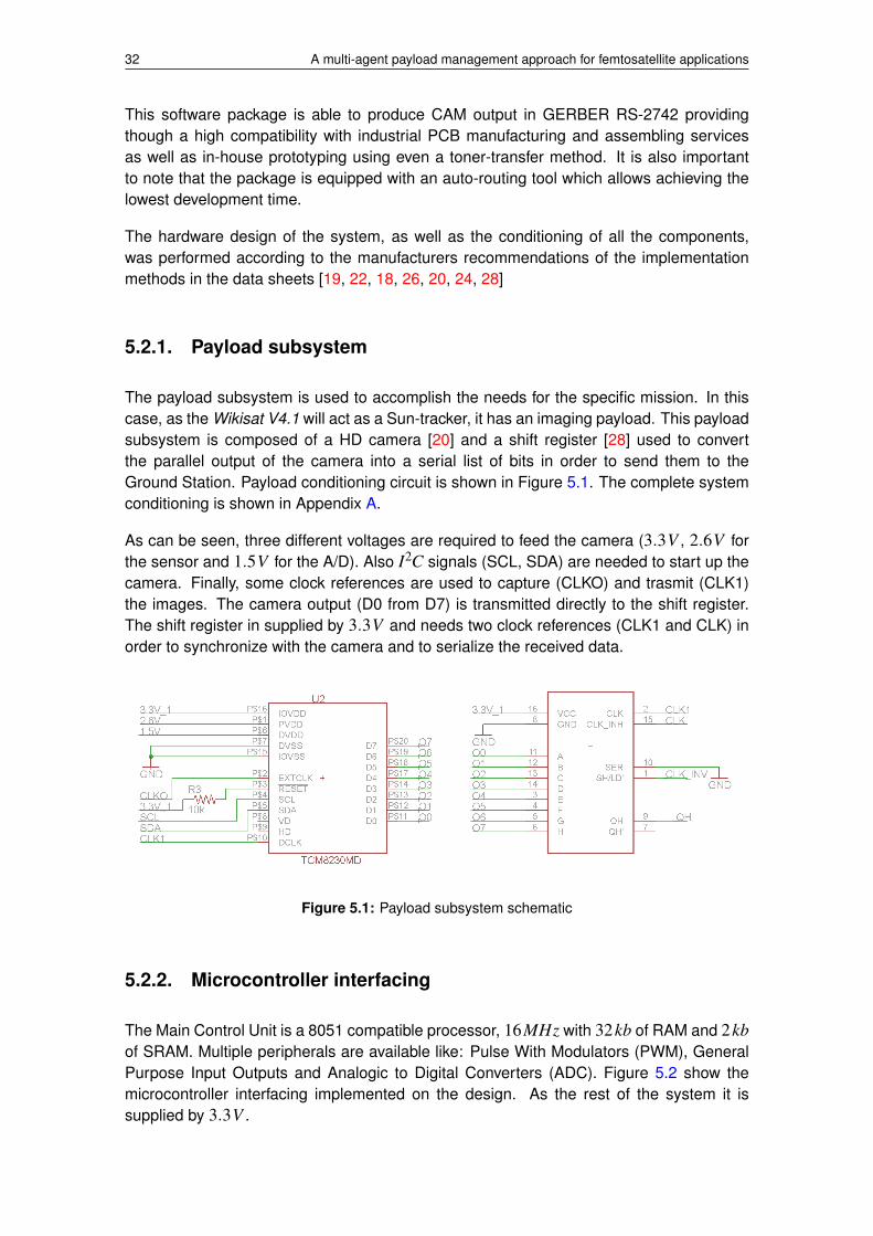
5.2.1. Payload subsystem
The payload subsystem is used to accomplish the needs for the specific mission. In thiscase, as the Wikisat V4.1 will act as a Sun-tracker, it has an imaging payload. This payloadsubsystem is composed of a HD camera [20] and a shift register [28] used to convertthe parallel output of the camera into a serial list of bits in order to send them to theGround Station. Payload conditioning circuit is shown in Figure 5.1. The complete systemconditioning is shown in Appendix A.
As can be seen, three different voltages are required to feed the camera (3.3V , 2.6V forthe sensor and 1.5V for the A/D). Also I2C signals (SCL, SDA) are needed to start up thecamera. Finally, some clock references are used to capture (CLKO) and trasmit (CLK1)the images. The camera output (D0 from D7) is transmitted directly to the shift register.The shift register in supplied by 3.3V and needs two clock references (CLK1 and CLK) inorder to synchronize with the camera and to serialize the received data.
Figure 5.1: Payload subsystem schematic
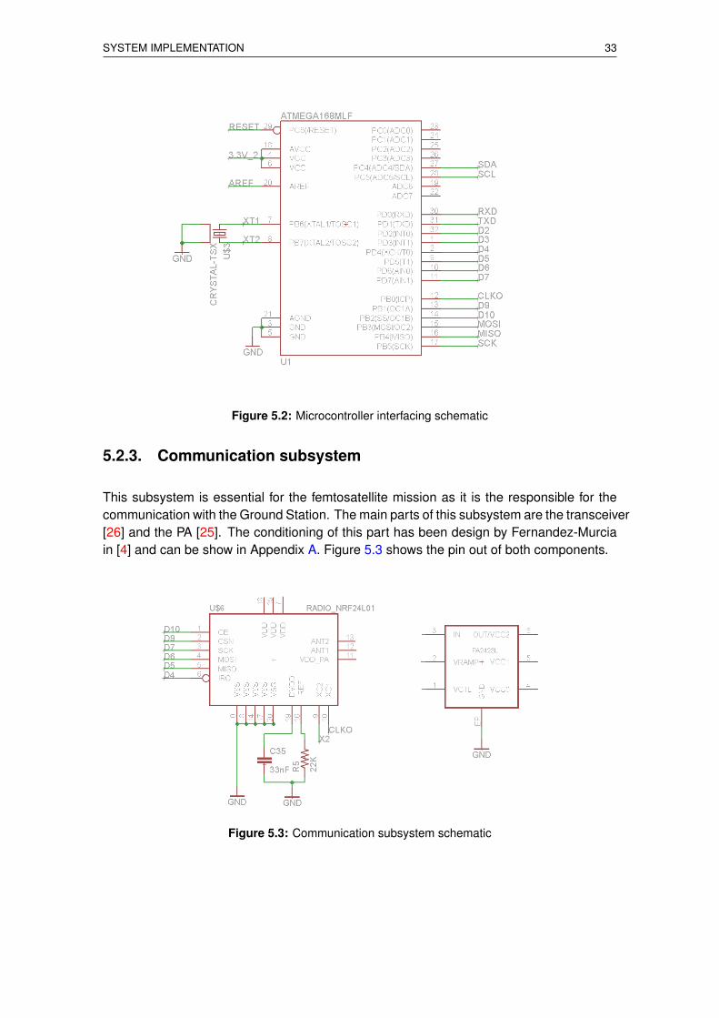
5.2.2. Microcontroller interfacing
The Main Control Unit is a 8051 compatible processor, 16MHz with 32kb of RAM and 2kbof SRAM. Multiple peripherals are available like: Pulse With Modulators (PWM), GeneralPurpose Input Outputs and Analogic to Digital Converters (ADC). Figure 5.2 show themicrocontroller interfacing implemented on the design. As the rest of the system it issupplied by 3.3V .
SYSTEM IMPLEMENTATION 33
Figure 5.2: Microcontroller interfacing schematic
5.2.3. Communication subsystem
This subsystem is essential for the femtosatellite mission as it is the responsible for thecommunication with the Ground Station. The main parts of this subsystem are the transceiver[26] and the PA [25]. The conditioning of this part has been design by Fernandez-Murciain [4] and can be show in Appendix A. Figure 5.3 shows the pin out of both components.
Figure 5.3: Communication subsystem schematic
34 A multi-agent payload management approach for femtosatellite applications
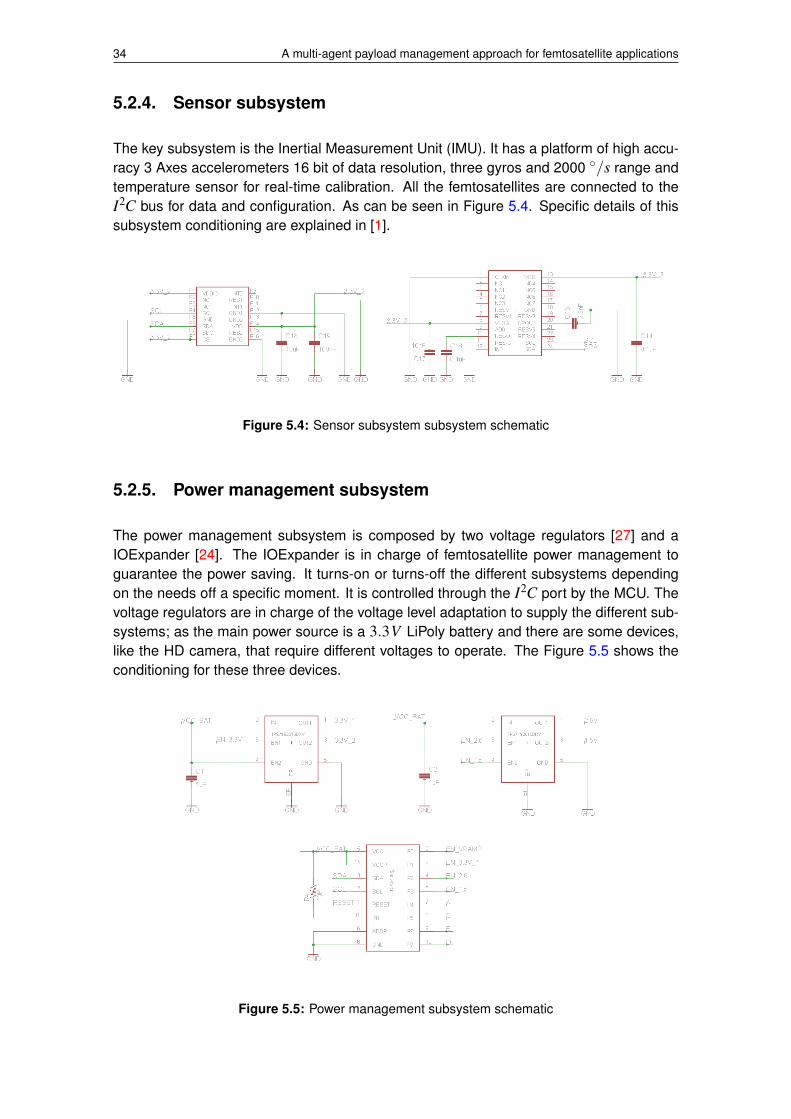
5.2.4. Sensor subsystem
The key subsystem is the Inertial Measurement Unit (IMU). It has a platform of high accu-racy 3 Axes accelerometers 16 bit of data resolution, three gyros and 2000 ◦/s range andtemperature sensor for real-time calibration. All the femtosatellites are connected to theI2C bus for data and configuration. As can be seen in Figure 5.4. Specific details of thissubsystem conditioning are explained in [1].
Figure 5.4: Sensor subsystem subsystem schematic
5.2.5. Power management subsystem
The power management subsystem is composed by two voltage regulators [27] and aIOExpander [24]. The IOExpander is in charge of femtosatellite power management toguarantee the power saving. It turns-on or turns-off the different subsystems dependingon the needs off a specific moment. It is controlled through the I2C port by the MCU. Thevoltage regulators are in charge of the voltage level adaptation to supply the different sub-systems; as the main power source is a 3.3V LiPoly battery and there are some devices,like the HD camera, that require different voltages to operate. The Figure 5.5 shows theconditioning for these three devices.
Figure 5.5: Power management subsystem schematic
SYSTEM IMPLEMENTATION 35
5.3. Board
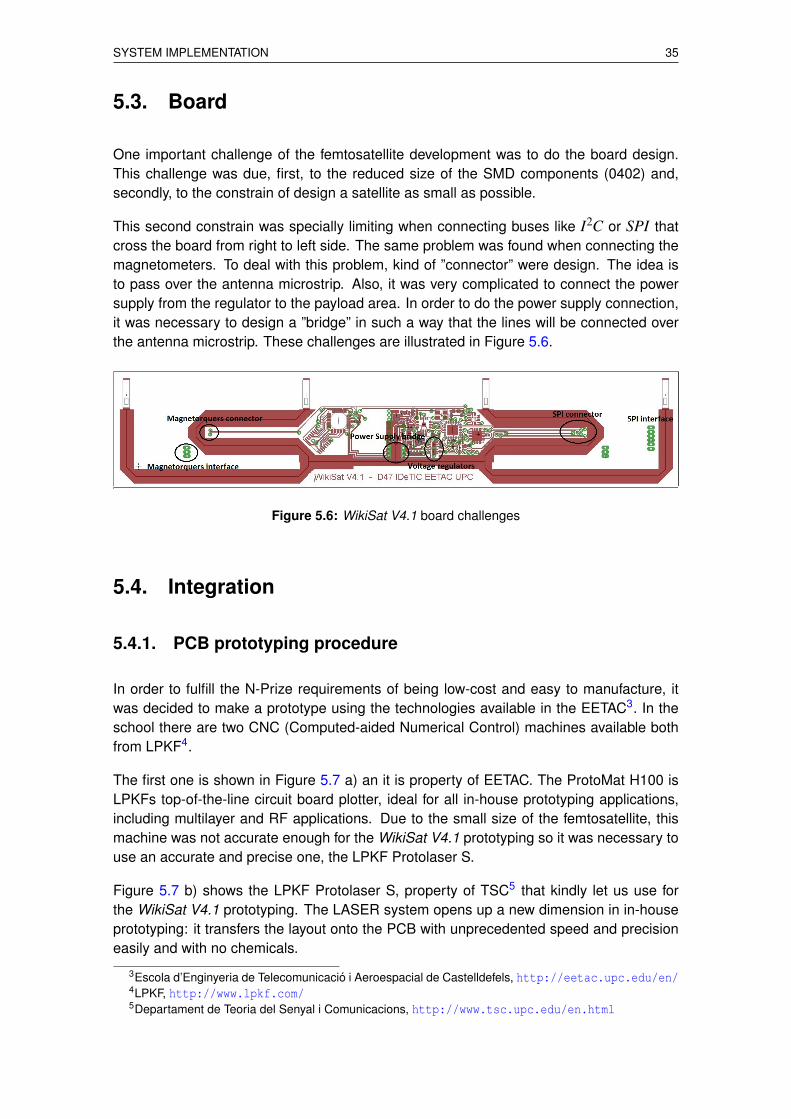
One important challenge of the femtosatellite development was to do the board design.This challenge was due, first, to the reduced size of the SMD components (0402) and,secondly, to the constrain of design a satellite as small as possible.
This second constrain was specially limiting when connecting buses like I2C or SPI thatcross the board from right to left side. The same problem was found when connecting themagnetometers. To deal with this problem, kind of ”connector” were design. The idea isto pass over the antenna microstrip. Also, it was very complicated to connect the powersupply from the regulator to the payload area. In order to do the power supply connection,it was necessary to design a ”bridge” in such a way that the lines will be connected overthe antenna microstrip. These challenges are illustrated in Figure 5.6.
Figure 5.6: WikiSat V4.1 board challenges
5.4. Integration
5.4.1. PCB prototyping procedure
In order to fulfill the N-Prize requirements of being low-cost and easy to manufacture, itwas decided to make a prototype using the technologies available in the EETAC3. In theschool there are two CNC (Computed-aided Numerical Control) machines available bothfrom LPKF4.
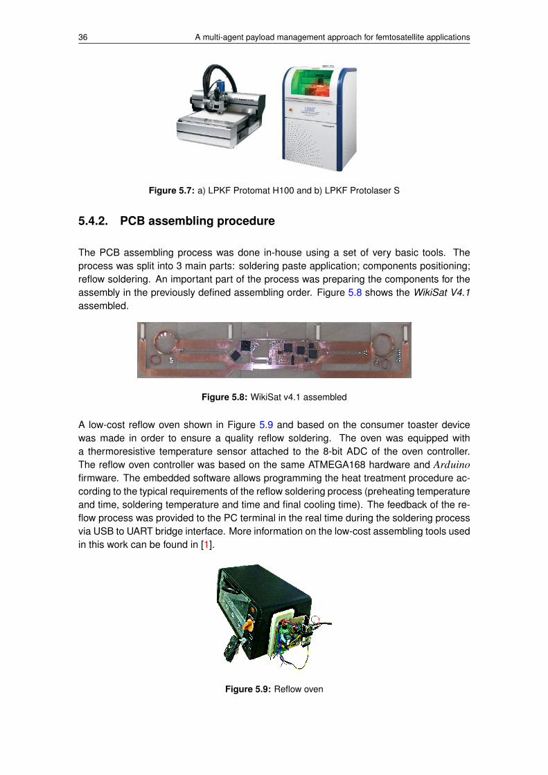
The first one is shown in Figure 5.7 a) an it is property of EETAC. The ProtoMat H100 isLPKFs top-of-the-line circuit board plotter, ideal for all in-house prototyping applications,including multilayer and RF applications. Due to the small size of the femtosatellite, thismachine was not accurate enough for the WikiSat V4.1 prototyping so it was necessary touse an accurate and precise one, the LPKF Protolaser S.
Figure 5.7 b) shows the LPKF Protolaser S, property of TSC5 that kindly let us use forthe WikiSat V4.1 prototyping. The LASER system opens up a new dimension in in-houseprototyping: it transfers the layout onto the PCB with unprecedented speed and precisioneasily and with no chemicals.
3Escola d’Enginyeria de Telecomunicacio i Aeroespacial de Castelldefels, http://eetac.upc.edu/en/4LPKF, http://www.lpkf.com/5Departament de Teoria del Senyal i Comunicacions, http://www.tsc.upc.edu/en.html
36 A multi-agent payload management approach for femtosatellite applications
Figure 5.7: a) LPKF Protomat H100 and b) LPKF Protolaser S
5.4.2. PCB assembling procedure
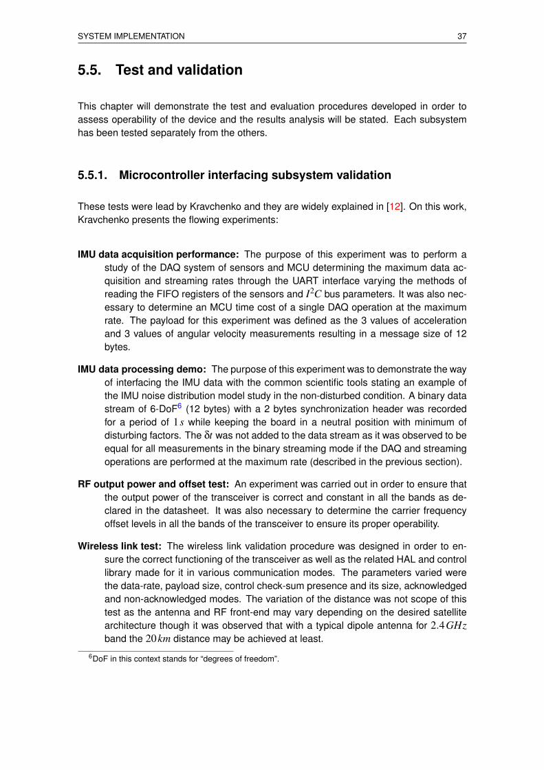
The PCB assembling process was done in-house using a set of very basic tools. Theprocess was split into 3 main parts: soldering paste application; components positioning;reflow soldering. An important part of the process was preparing the components for theassembly in the previously defined assembling order. Figure 5.8 shows the WikiSat V4.1assembled.
Figure 5.8: WikiSat v4.1 assembled
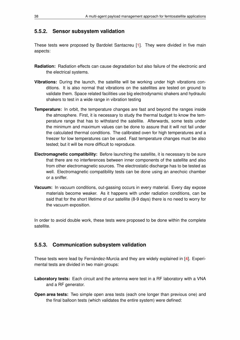
A low-cost reflow oven shown in Figure 5.9 and based on the consumer toaster devicewas made in order to ensure a quality reflow soldering. The oven was equipped witha thermoresistive temperature sensor attached to the 8-bit ADC of the oven controller.The reflow oven controller was based on the same ATMEGA168 hardware and Arduinofirmware. The embedded software allows programming the heat treatment procedure ac-cording to the typical requirements of the reflow soldering process (preheating temperatureand time, soldering temperature and time and final cooling time). The feedback of the re-flow process was provided to the PC terminal in the real time during the soldering processvia USB to UART bridge interface. More information on the low-cost assembling tools usedin this work can be found in [1].
Figure 5.9: Reflow oven
SYSTEM IMPLEMENTATION 37
5.5. Test and validation
This chapter will demonstrate the test and evaluation procedures developed in order toassess operability of the device and the results analysis will be stated. Each subsystemhas been tested separately from the others.
5.5.1. Microcontroller interfacing subsystem validation
These tests were lead by Kravchenko and they are widely explained in [12]. On this work,Kravchenko presents the flowing experiments:
IMU data acquisition performance: The purpose of this experiment was to perform astudy of the DAQ system of sensors and MCU determining the maximum data ac-quisition and streaming rates through the UART interface varying the methods ofreading the FIFO registers of the sensors and I2C bus parameters. It was also nec-essary to determine an MCU time cost of a single DAQ operation at the maximumrate. The payload for this experiment was defined as the 3 values of accelerationand 3 values of angular velocity measurements resulting in a message size of 12bytes.
IMU data processing demo: The purpose of this experiment was to demonstrate the wayof interfacing the IMU data with the common scientific tools stating an example ofthe IMU noise distribution model study in the non-disturbed condition. A binary datastream of 6-DoF6 (12 bytes) with a 2 bytes synchronization header was recordedfor a period of 1s while keeping the board in a neutral position with minimum ofdisturbing factors. The δt was not added to the data stream as it was observed to beequal for all measurements in the binary streaming mode if the DAQ and streamingoperations are performed at the maximum rate (described in the previous section).
RF output power and offset test: An experiment was carried out in order to ensure thatthe output power of the transceiver is correct and constant in all the bands as de-clared in the datasheet. It was also necessary to determine the carrier frequencyoffset levels in all the bands of the transceiver to ensure its proper operability.
Wireless link test: The wireless link validation procedure was designed in order to en-sure the correct functioning of the transceiver as well as the related HAL and controllibrary made for it in various communication modes. The parameters varied werethe data-rate, payload size, control check-sum presence and its size, acknowledgedand non-acknowledged modes. The variation of the distance was not scope of thistest as the antenna and RF front-end may vary depending on the desired satellitearchitecture though it was observed that with a typical dipole antenna for 2.4GHzband the 20km distance may be achieved at least.
6DoF in this context stands for “degrees of freedom”.
38 A multi-agent payload management approach for femtosatellite applications
5.5.2. Sensor subsystem validation
These tests were proposed by Bardolet Santacreu [1]. They were divided in five mainaspects:
Radiation: Radiation effects can cause degradation but also failure of the electronic andthe electrical systems.
Vibrations: During the launch, the satellite will be working under high vibrations con-ditions. It is also normal that vibrations on the satellites are tested on ground tovalidate them. Space related facilities use big electrodynamic shakers and hydraulicshakers to test in a wide range in vibration testing
Temperature: In orbit, the temperature changes are fast and beyond the ranges insidethe atmosphere. First, it is necessary to study the thermal budget to know the tem-perature range that has to withstand the satellite. Afterwards, some tests underthe minimum and maximum values can be done to assure that it will not fail underthe calculated thermal conditions. The calibrated oven for high temperatures and afreezer for low temperatures can be used. Fast temperature changes must be alsotested; but it will be more difficult to reproduce.
Electromagnetic compatibility: Before launching the satellite, it is necessary to be surethat there are no interferences between inner components of the satellite and alsofrom other electromagnetic sources. The electrostatic discharge has to be tested aswell. Electromagnetic compatibility tests can be done using an anechoic chamberor a sniffer.
Vacuum: In vacuum conditions, out-gassing occurs in every material. Every day exposematerials become weaker. As it happens with under radiation conditions, can besaid that for the short lifetime of our satellite (8-9 days) there is no need to worry forthe vacuum exposition.
In order to avoid double work, these tests were proposed to be done within the completesatellite.
5.5.3. Communication subsystem validation
These tests were lead by Fernandez-Murcia and they are widely explained in [4]. Experi-mental tests are divided in two main groups:
Laboratory tests: Each circuit and the antenna were test in a RF laboratory with a VNAand a RF generator.
Open area tests: Two simple open area tests (each one longer than previous one) andthe final balloon tests (which validates the entire system) were defined:

SYSTEM IMPLEMENTATION 39
400m test. This is only a quick test to assure all works as expected. All wasas expected.
6,5 kilometers test. This is critical because determines if all the work done be-fore goes in a good direction or not. After some problems in transceivers feed-ing, spot and antennas pointing, the tests finished satisfactorily (from 41.26784,1.923287 to 41.265227, 1.996071). A 7dBm power transmission achieved us-ing PA2423L [25]. No LNA on reception.
5.5.4. Power management subsystem validation
This subsystem includes the IOExpander [24] and the voltage regulators [27].
For the IOExpander, an evaluation board shown in Figure 5.10 was designer. This boardwill facilitate connect the device to the Arduino7 in order to undergo some tests. Thedeveloped code is shown in Appedix D.1. Due to the lack of time, this board was designedbut not build, so this test remain pending for further work.
Figure 5.10: IOExpander evaluation board
In order to study the behavior of the regulator a practical case has been used. First of all,as with the rest of IC, an evaluation board was built. This board is shown in Figure 5.11.For this experiment the T PS7192615 regulator was selected to supply the HD Camera [20]during its tests. The voltage was directly connected to the Arduino output voltage (3.3V )in order to simulate an scenario as closer as possible to the mission one. Some measure-ments of the output voltages of the regulator were done and they were the expected ones.As the HD Camera worked properly during the tests, can be assured that this device willperform correctly during the mission.
7Seeduino v2.21 with ATmega328P has been used, http://www.seeedstudio.com/depot/seeeduino-v221-atmega-328p-p-669.html
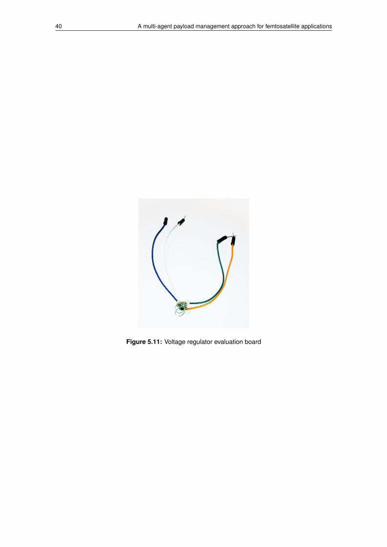
40 A multi-agent payload management approach for femtosatellite applications
Figure 5.11: Voltage regulator evaluation board
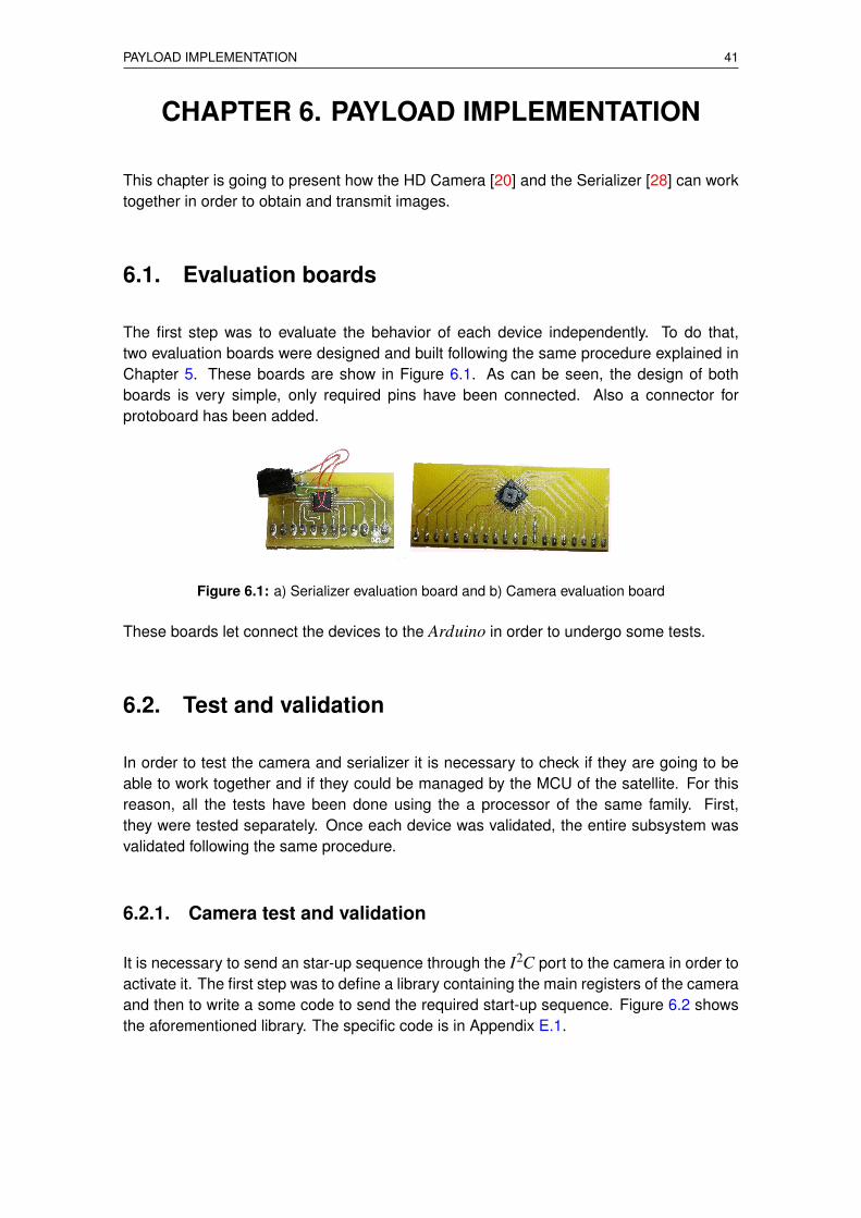
PAYLOAD IMPLEMENTATION 41
CHAPTER 6. PAYLOAD IMPLEMENTATION
This chapter is going to present how the HD Camera [20] and the Serializer [28] can worktogether in order to obtain and transmit images.
6.1. Evaluation boards
The first step was to evaluate the behavior of each device independently. To do that,two evaluation boards were designed and built following the same procedure explained inChapter 5. These boards are show in Figure 6.1. As can be seen, the design of bothboards is very simple, only required pins have been connected. Also a connector forprotoboard has been added.
Figure 6.1: a) Serializer evaluation board and b) Camera evaluation board
These boards let connect the devices to the Arduino in order to undergo some tests.
6.2. Test and validation
In order to test the camera and serializer it is necessary to check if they are going to beable to work together and if they could be managed by the MCU of the satellite. For thisreason, all the tests have been done using the a processor of the same family. First,they were tested separately. Once each device was validated, the entire subsystem wasvalidated following the same procedure.
6.2.1. Camera test and validation
It is necessary to send an star-up sequence through the I2C port to the camera in order toactivate it. The first step was to define a library containing the main registers of the cameraand then to write a some code to send the required start-up sequence. Figure 6.2 showsthe aforementioned library. The specific code is in Appendix E.1.
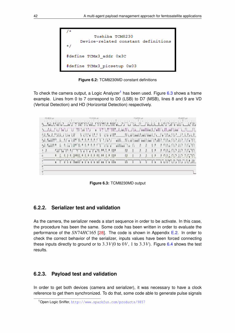
42 A multi-agent payload management approach for femtosatellite applications
Figure 6.2: TCM8230MD constant definitions
To check the camera output, a Logic Analyzer1 has been used. Figure 6.3 shows a frameexample. Lines from 0 to 7 correspond to D0 (LSB) to D7 (MSB), lines 8 and 9 are VD(Vertical Detection) and HD (Horizontal Detection) respectively.
Figure 6.3: TCM8230MD output
6.2.2. Serializer test and validation
As the camera, the serializer needs a start sequence in order to be activate. In this case,the procedure has been the same. Some code has been written in order to evaluate theperformance of the SN74HC165 [28]. The code is shown in Appendix E.2. In order tocheck the correct behavior of the serializer, inputs values have been forced connectingthese inputs directly to ground or to 3.3V (0 to 0V , 1 to 3.3V ). Figure 6.4 shows the testresults.
6.2.3. Payload test and validation
In order to get both devices (camera and serializer), it was necessary to have a clockreference to get them synchronized. To do that, some code able to generate pulse signals
1Open Logic Sniffer, http://www.sparkfun.com/products/9857
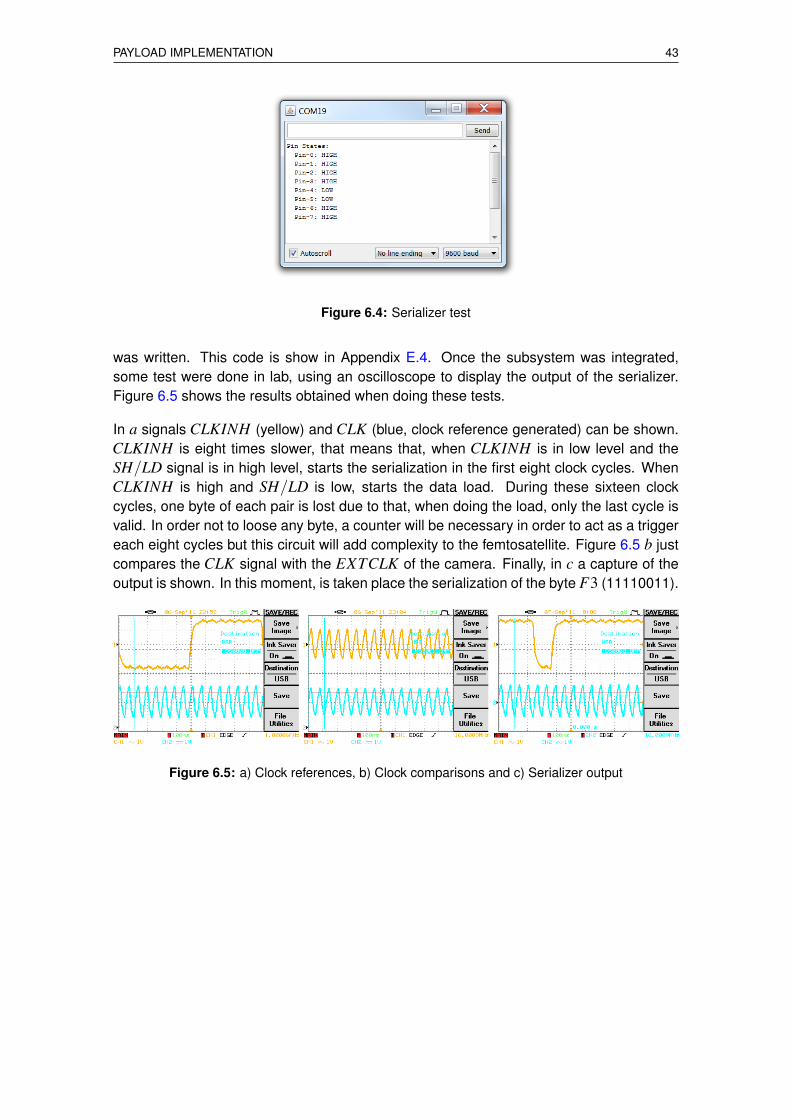
PAYLOAD IMPLEMENTATION 43
Figure 6.4: Serializer test
was written. This code is show in Appendix E.4. Once the subsystem was integrated,some test were done in lab, using an oscilloscope to display the output of the serializer.Figure 6.5 shows the results obtained when doing these tests.
In a signals CLKINH (yellow) and CLK (blue, clock reference generated) can be shown.CLKINH is eight times slower, that means that, when CLKINH is in low level and theSH/LD signal is in high level, starts the serialization in the first eight clock cycles. WhenCLKINH is high and SH/LD is low, starts the data load. During these sixteen clockcycles, one byte of each pair is lost due to that, when doing the load, only the last cycle isvalid. In order not to loose any byte, a counter will be necessary in order to act as a triggereach eight cycles but this circuit will add complexity to the femtosatellite. Figure 6.5 b justcompares the CLK signal with the EXTCLK of the camera. Finally, in c a capture of theoutput is shown. In this moment, is taken place the serialization of the byte F3 (11110011).
Figure 6.5: a) Clock references, b) Clock comparisons and c) Serializer output

44 A multi-agent payload management approach for femtosatellite applications

CONCLUSIONS 45
CHAPTER 7. CONCLUSIONS
7.1. General conclusions
During the development of this project the entire WikiSat team has explored in a prac-tical case of a new paradigm for the development of very small space missions. Thisnew approach of development can result, if successful, in the birth of a new market forfemtosatellites. These kind of missions should be very focused on a single goal, but thesystem can perform most of the typical applications undertaken by larger mass systems.However, it must be stated that very small satellites will not enter into competition withstandard satellites. They could open new markets and opportunities, could be used foreducation, disaster management and even communications on an extremely low cost andcomplexity.
It has been demonstrated that it is possible to design, test and build a femtosatellite (withless than 20 grams) that is able to perform a short duration mission. Specifically a Sun-tracker mission has been developed. Likewise, an example of with an imaging payloadwith an HD Camera have been designed and implementer. Finally, it has been proved thatthe new space payload paradigm can contribute to a simpler, faster and much cheaperway of producing very small missions.
7.2. Environmental impact
The achievement of this project will deliver a satellite to the space. The launch phaseis the most contaminant stage of the mission, but debris will reenter soon into the Earthatmosphere. Low cost and lead-free materials were used in this project in order to minimizeenvironmental impact. To reduce the amount of waste produced during the work somerecycled components were used. All the boards with production defects were recycledand reused in other prototypes as well.
This project does not mean an important impact upon the environment because of thereduced sizes and the low orbit used. The estimated time of the re-entry is between 8 and9 days so it can be assured that there will be no generation of space debris. The smallsize of the femtosatellite assures that it will be disintegrated during the re-entry. For themini-launcher, it is necessary to study all cases but the idea is not to generated debriseither. Moreover, the pollution generated will be much lower that the generated by a biglauncher. So, the use of small mini-launcher not only implies a reduction of cost, but alsoa reduction in pollution and a lower impact on the environment. This kind of small sizetechnologies also is translated into power savings.
Regarding the economic and social field, the use of low cost technologies for space ap-plications can open a market that has been inaccessible for many years. Governments,companies and organizations unable to afford the costs of space missions may will takebenefit from this project.

46 A multi-agent payload management approach for femtosatellite applications
7.3. Future work
It is also important to mention that further experimentation and research work is required insuch fields like image processing and storage. It is necessary to improve these aspects inorder to be able to obtain a good quality image fulfilling the system requirements explainedin Chapter 2.
Another development challenge will be introduction of new improved devices such:
A three axes accelerometer and compass single chip like the LSM303DLHC [21]from STMicroelectronics. It is going to used to guide the launcher during the trajectory-
The L3G4200D [23] from STMicroelectronics, a three axes gyro that is going to beused for short maneuvers for the camera or antenna pointing.
The WikiSat team is already working in the WikiSat V.5. This version will include theimprovements explained above.

BIBLIOGRAPHY 47
BIBLIOGRAPHY
[1] E. Bardolet. Study of a low cost inertial platfom for a femto-satellite deployed by amini-launcher, 2010.
[2] Lluis Bonet. High altitude balloon mission design and implementation for a mini-launcher. Master’s thesis, Universitat Politecnica de Catalunya, 2011.
[3] et al. D. J. Barnhart. A low-cost femtosatellite to enable distributed space missions.Acta Astronautica 64, 2009.
[4] Enric Fernandez Murcia et al. A synthetic aperture antenna for femto-satellitesbased on commercial-of-the-shelf. 29th Digital Avionics Systems Conference. Seattle(2011), 2011.
[5] R. Gonzalez and J. Naudo. A multi-agent adaptive protocol for femto-satellite appli-cations. Master’s thesis, Universitat Politecnica de Catalunya, 2011.
[6] C. D. Hall. Virginia tech ionospheric scintillation measurement mission. 13th AnnualAIAA/USU Conference on Small Satellites, 1999.
[7] C. Hamroun. Design and prototype of a flight microstrip antennas for pico satelliteerpsat-1. 4ht International Conference, Istanbul, 2009.
[8] H. Helvajian. The fabrication of a 100 g co-orbiting satellite assistant (cosa) usingglass ceramic materials and 3-d. Proceedings of the Ninth International Microma-chine/Nanotech Symposium, Tokyo, Japan, 2003.
[9] H. Herman. HANDBOOK OF ASTRONAUTICAL ENGINEERING. Ed. McGraw-Hill,Inc., 1961.
[10] James R. Wertz et. al. Space Mission Engineering: The new SMAD, Chapter 1.4.7.Space Technology Library, 2011.
[11] et al. J. Tristancho. A probe of concept of femto-satellite based on commercial-of-the-shelf. 30th Digital Avionics Systems Conference, USA, 2011.
[12] Kravchenko, Victor Design and implementation of a femto-satellite technologydemonstrator. Master’s thesis, Universitat Politecnica de Catalunya, 2011.
[13] et al. K. Doerksen. Design, modeling and evaluation of a 2.4ghz fhss communicationssystem for narcissat. 17th AIAA/USU Conference on Small Satellites, Stanford, CA,USA, 2003.
[14] Laia Navarro Morcillo. Use of hardware-on-the-loop to test missions for a low costmini-launcher. Master’s thesis, Universitat Politecnica de Catalunya, 2011.
[15] Laia Molas Pous. Efectes de la radiacio sobre els components electronics d’un sateliten orbita al voltant de la terra. Master’s thesis, Universitat Politecnica de Catalunya,2011.
[16] Clayton Mowry. Interview on ”The Space Show”, 2010.

[17] Joshua Tristancho. Implementation of a femto-satellite and a mini-launcher. Master’sthesis, Universitat Politecnica de Catalunya, 2010.
[18] ST Electronics. LIS331HH Data Sheet. http://www.sparkfun.com/datasheets/Sensors/Accelerometer/LIS331HH.pdf, Last visit on 09/13/2011.
[19] Atmel. ATMega 168 Data Sheet. http://www.atmel.com/dyn/resources/prod_documents/doc2545.pdf, Last visit on 09/13/2011.
[20] TOSHIBA. TCM8230MD Data Sheet. http://www.sparkfun.com/datasheets/Sensors/Imaging/TCM8230MD.pdf, Last visit on 09/13/2011.
[21] ST Electronics. LSM303DLHC Data Sheet. http://www.st.com/internet/com/TECHNICAL_RESOURCES/TECHNICAL_LITERATURE/DATASHEET/DM00027543.pdf,Last visit on 09/13/2011.
[22] InvenSense. ITG-3200 Data Sheet. http://invensense.com/mems/gyro/documents/EB-ITG-3200-00-01.1.pdf, Last visit on 09/13/2011.
[23] ST Electronics. L3G4200D Data Sheet. http://www.st.com/internet/com/TECHNICAL_RESOURCES/TECHNICAL_LITERATURE/DATASHEET/CD00265057.pdf,Last visit on 09/13/2011.
[24] Texas Instruments. TCA6408 Data Sheet. http://www.ti.com/lit/ds/symlink/tca6408.pdf, Last visit on 09/13/2011.
[25] SiGe Semiconductor. PA2423L Data Sheet. http://www.skyworksinc.com/uploads/documents/SiGe/13-DST-01_PA2423L_Brief_Rev_4p1_AP_May-26-2009.pdf, Last visit on 09/13/2011.
[26] Nordic Semiconductor. nRF24L01+ Data Sheet. http://www.nordicsemi.com/eng/Products/2.4GHz-RF/nRF24L01P, Last visit on 09/13/2011.
[27] Texas Instruments. TPS719XXXX Data Sheet. http://www.ti.com/lit/ds/symlink/tps71918-12.pdf, Last visit on 09/13/2011.
[28] Texas Instruments. SN74HC165 Data Sheet. http://www.sparkfun.com/datasheets/Components/General/sn74hc165.pdf, Last visit on 09/13/2011.
http://www.skyworksinc.com/uploads/documents/SiGe/13-DST-01_PA2423L_Brief_Rev_4p1_AP_May-26-2009.pdf
http://www.skyworksinc.com/uploads/documents/SiGe/13-DST-01_PA2423L_Brief_Rev_4p1_AP_May-26-2009.pdf

APPENDIX

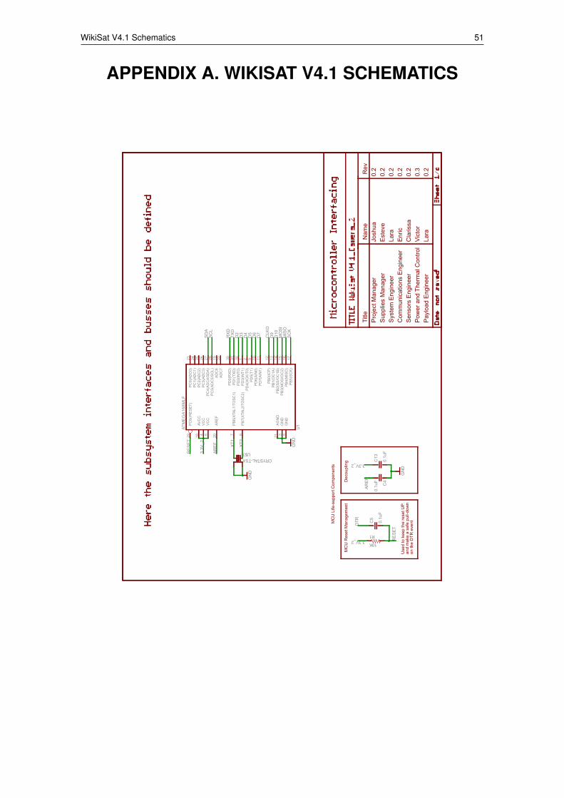
WikiSat V4.1 Schematics 51
APPENDIX A. WIKISAT V4.1 SCHEMATICS
ATM
EG
A16
8MLF
GN
D
10K
0.1u
F0.
1uF
GN
D
GN
D
0.1u
F
CRYSTAL-TSX
ADC
619
ADC
722
AGN
D21
AREF
20
AVC
C18
GN
D3
GN
D5
PB0(
ICP)
12
PB1(
OC
1A)
13
PB2(
SS/O
C1B
)14
PB3(
MO
SI/O
C2)
15
PB4(
MIS
O)
16
PB5(
SCK)
17
PB6(
XTAL
1/TO
SC1)
7
PB7(
XTAL
2/TO
SC2)
8
PC0(
ADC
0)23
PC1(
ADC
1)24
PC2(
ADC
2)25
PC3(
ADC
3)26
PC4(
ADC
4/SD
A)27
PC5(
ADC
5/SC
L)28
PC6(
/RES
ET)
29
PD0(
RXD
)30
PD1(
TXD
)31
PD2(
INT0
)32
PD3(
INT1
)1
PD4(
XCK/
T0)
2
PD5(
T1)
9
PD6(
AIN
0)10
PD7(
AIN
1)11
VCC
4
VCC
6
U1
R1
C5
C13
C4
U$3
TXD
RX
D
DTR
SC
KM
ISO
MO
SI
SD
AS
CL
CLK
OD
9
D7
D2
D3
D4
D5
D6
D10
RE
SE
T
RE
SE
T
AR
EF
AR
EF
XT1
XT2
3.3V
_2
3.3V_2
3.3V_2
Use
d to
kee
p th
e re
set U
Pan
d m
ake
a sa
fe p
ull-d
own
on th
e D
TR e
vent
MC
U R
eset
Man
agem
ent
Dec
oupl
ing
MC
U L
ife-s
uppo
rt C
ompo
nent
s
Pro
ject
Man
ager
Sys
tem
Eng
inee
rC
omm
unic
atio
ns E
ngin
eer
Sen
sors
Eng
inee
r
Pay
load
Eng
inee
rP
ower
and
The
rmal
Con
trol
Sup
plie
s M
anag
er
Title
Nam
eR
evJo
shua
0.2
Est
eve
0.2
Lara
0.2
Enr
ic0.
20.
2C
laris
saVi
ctor
0.3
0.2
Lara
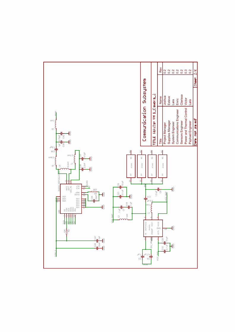
RA
DIO
_NR
F24L
01S
MD
10K
GN
D
33nF
22K
GN
D
8.2n
H
2.7nH3.9nH
2.2n
F4.
7pF
1.5pF 1pF
GN
DG
ND
GN
D
10nF
1nF
GN
DG
ND
1nH
0.75
pF
GN
D
1 pF 4,7 pF
1 pF
1,5
pF
1 pF
2.2 pF
1nH
0,1
uF15
pF
GN
DG
ND
GN
D
1nH
0,1
uF
GN
D
10 p
F
ANT1
12AN
T213
CE
1
CSN
2
DVDD 19
IREF 16
IRQ
6M
ISO
5M
OSI
4SC
K3
VDD7 VDD15 VDD18
VDD
_PA
11
VSS 0
VSS 8
VSS 14
VSS 17
VSS 20
XC1 10XC2 9
U$6
R2
C35
R5
L6
L7L8
C36
C37
C38
C39
C40
C41
L9
C42
VCTL
1
VRAM
P2
IN3
GND EP
VCC
04
VCC
15
OU
T/VC
C2
6
PA24
23L
C3 C6
C7
C9
C10
C11
L1
C12
C20
L2C
21C
8
NC
NC
FPFP
AT29
50
NC
NC
FPFP
AT29
50
NC
NC
FPFP
AT29
50
NC
NC
FPFP
AT29
50
X2C
LKO
D7
D4
D5
D6
D10
RFI
N2
RFIN2
VC
C_B
AT
VC
C_B
AT
VC
C_B
AT
AN
T
EN
_VR
AM
P
D9
3.3V
_1
Pro
ject
Man
ager
Sys
tem
Eng
inee
rC
omm
unic
atio
ns E
ngin
eer
Sen
sors
Eng
inee
r
Pay
load
Eng
inee
rP
ower
and
The
rmal
Con
trol
Sup
plie
s M
anag
er
Title
Nam
eR
evJo
shua
0.2
Est
eve
0.2
Lara
0.2
Enr
ic0.
20.
2C
laris
saVi
ctor
0.3
0.2
Lara
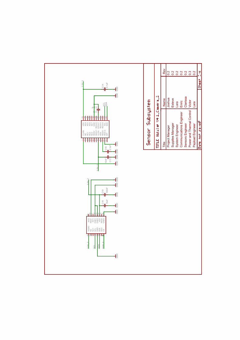
GN
D
0.1u
F
GN
D
2.2nF
0.1u
F
GN
DG
ND
10nF
GN
DG
ND
GN
D
10uF
100n
F
GN
DG
ND
GN
DG
ND
GN
D
AD0
9
CLK
IN1
CPO
UT
20
GN
D18
INT
12
NC
2
NC
13
NC
24
NC
35
NC
414
NC
515
NC
616
NC
717
REG
O10
RES
-G11
RES
V6
RES
V17
RES
V219
RES
V321
RES
V422
SCL
23
SDA
24
VDD
13
VLO
G8
C14
C15
C16
C17
CS
P8
GN
DP5
GN
D1
P12
GN
D2
P13
GN
D3
P16
INT1
P11
INT2
P9
NC
P2
NC
1P3
RES
1P1
0
RES
2P1
5
SCL
P4
SDA
P6
SDO
P7VD
DP1
4
VDD
IOP1
C18
C19
SD
A
SD
A
SC
L
SC
L
3.3V
_2
3.3V
_2
3.3V
_2
3.3V
_2
3.3V
_2
Pro
ject
Man
ager
Sys
tem
Eng
inee
rC
omm
unic
atio
ns E
ngin
eer
Sen
sors
Eng
inee
r
Pay
load
Eng
inee
rP
ower
and
The
rmal
Con
trol
Sup
plie
s M
anag
er
Title
Nam
eR
evJo
shua
0.2
Est
eve
0.2
Lara
0.2
Enr
ic0.
20.
2C
laris
saVi
ctor
0.3
0.2
Lara
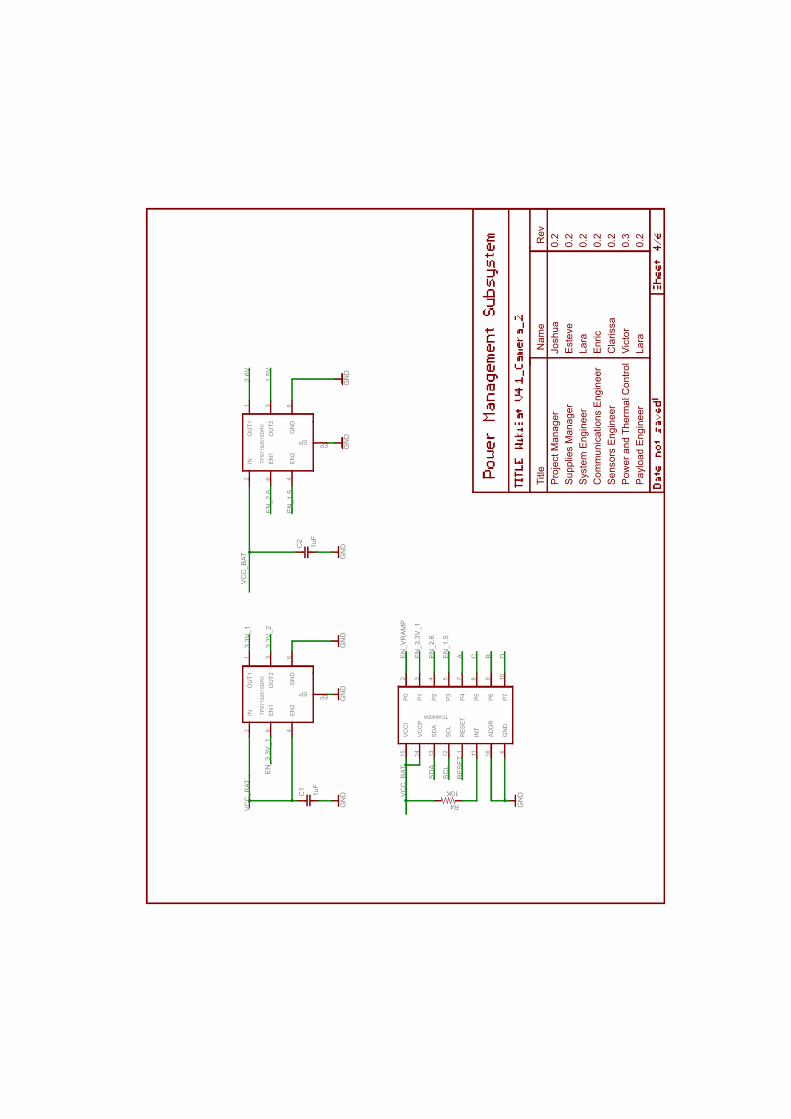
GN
DG
ND
1uF
1uF
GN
DG
ND
GN
DG
ND
GN
D
10K
IN2
EN1
6
EN2
4
OU
T11
OU
T23
GN
D5
EP EP
TPS
7192
615D
RV
C1
C2
IN2
EN1
6
EN2
4
OU
T11
OU
T23
GN
D5
EP EP
TPS
7192
615D
RV
VCC
I15
VCC
P14
SDA
13
SCL
12
RES
ET1
INT
11
ADD
R16
GN
D6
P710
P69
P58
P47
P35
P24
P13
P02
TCA6408A
R4
VC
C_B
AT
VC
C_B
ATV
CC
_BAT
2.6V
1.5V
3.3V
_1
3.3V
_2
SD
A
SC
L
RE
SE
T
EN
_2.6
EN
_2.6
EN
_1.5
EN
_1.5
A DBC
EN
_3.3
V_1
EN
_3.3
V_1
EN
_VR
AM
P
Pro
ject
Man
ager
Sys
tem
Eng
inee
rC
omm
unic
atio
ns E
ngin
eer
Sen
sors
Eng
inee
r
Pay
load
Eng
inee
rP
ower
and
The
rmal
Con
trol
Sup
plie
s M
anag
er
Title
Nam
eR
evJo
shua
0.2
Est
eve
0.2
Lara
0.2
Enr
ic0.
20.
2C
laris
saVi
ctor
0.3
0.2
Lara
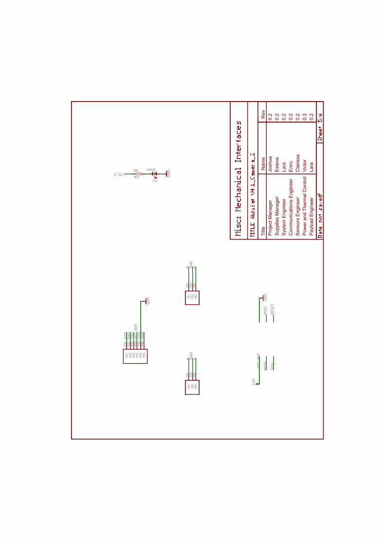
10K
Green
GN
D
3.3V
GN
D
GN
D
R6
D3
P$1
P$1
P$2
P$2
P$3
P$3
P$4
P$4
P$5
P$5
P$6
P$6
P$1
P$1
P$2
P$2
P$3
P$3
P$1
P$1
P$2
P$2
P$3
P$3
GN
DG
ND
GN
DG
ND
SC
K
MIS
OM
OS
I
RE
SE
T
DTR
RX
DTX
DV
CC
_BAT
VC
C_B
AT
C
B D
A
3.3V_2
Pro
ject
Man
ager
Sys
tem
Eng
inee
rC
omm
unic
atio
ns E
ngin
eer
Sen
sors
Eng
inee
r
Pay
load
Eng
inee
rP
ower
and
The
rmal
Con
trol
Sup
plie
s M
anag
er
Title
Nam
eR
evJo
shua
0.2
Est
eve
0.2
Lara
0.2
Enr
ic0.
20.
2C
laris
saVi
ctor
0.3
0.2
Lara
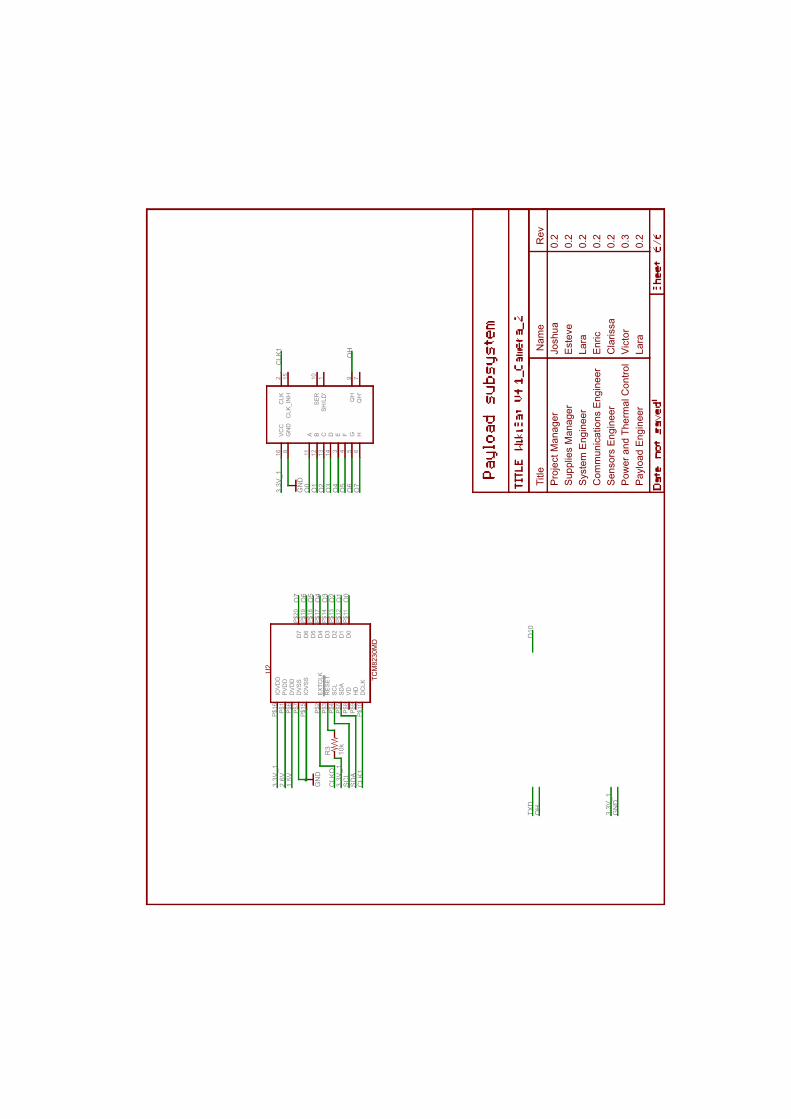
GN
D
10k
GN
D
PVD
DP$
1
EXTC
LKP$
2
RES
ETP$
3
SCL
P$4
SDA
P$5
DVD
DP$
6
DVS
SP$
7
VDP$
8
HD
P$9
DC
LKP$
10
D0
P$11
D1
P$12
D2
P$13
D3
P$14
IOVS
SP$
15
IOVD
DP$
16
D4
P$17
D5
P$18
D6
P$19
D7
P$20
VCC
16
GN
D8
A11
B12
C13
D14
E3
F4
G5
H6
CLK
2
CLK
_IN
H15
SER
10
SH/L
D'
1
QH
9
QH
'7
R3
O7
O7
O6
O6
O5
O5
O4
O4
O3
O3
O2
O2
O1
O1
O0
O0
2.6V
1.5V
GN
D
SC
LS
DA
CLK
1
CLK
1
CLK
O
QH
QH
3.3V
_13.
3V_1
3.3V
_1
3.3V
_1
TXD
D10
U2
TCM
8230
MD
Pro
ject
Man
ager
Sys
tem
Eng
inee
rC
omm
unic
atio
ns E
ngin
eer
Sen
sors
Eng
inee
r
Pay
load
Eng
inee
rP
ower
and
The
rmal
Con
trol
Sup
plie
s M
anag
er
Title
Nam
eR
evJo
shua
0.2
Est
eve
0.2
Lara
0.2
Enr
ic0.
20.
2C
laris
saVi
ctor
0.3
0.2
Lara
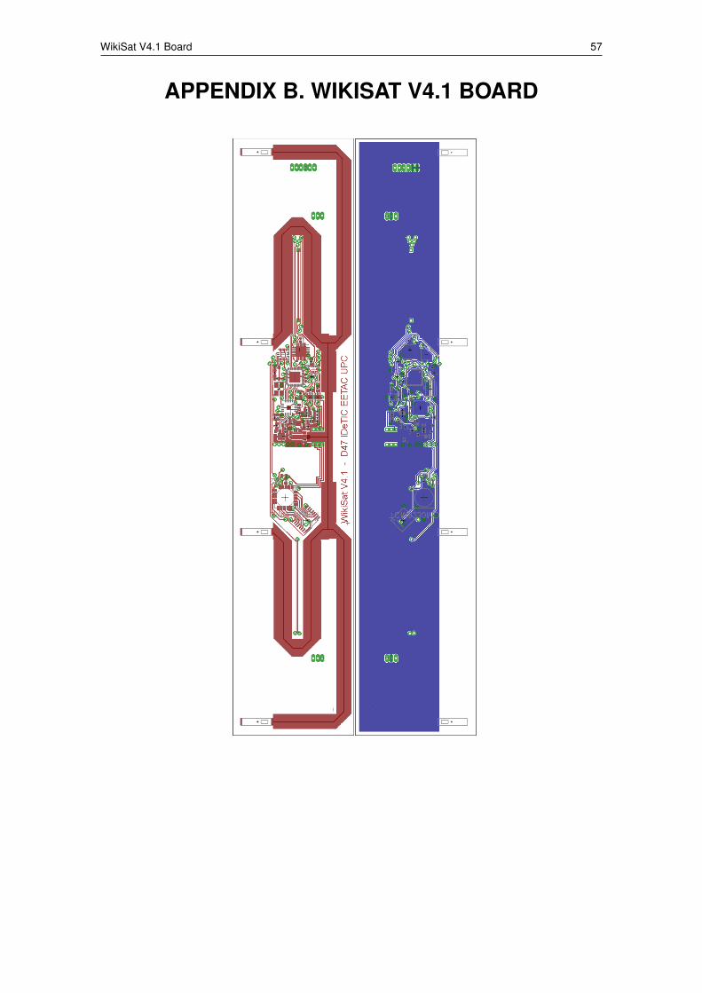
WikiSat V4.1 Board 57
APPENDIX B. WIKISAT V4.1 BOARD

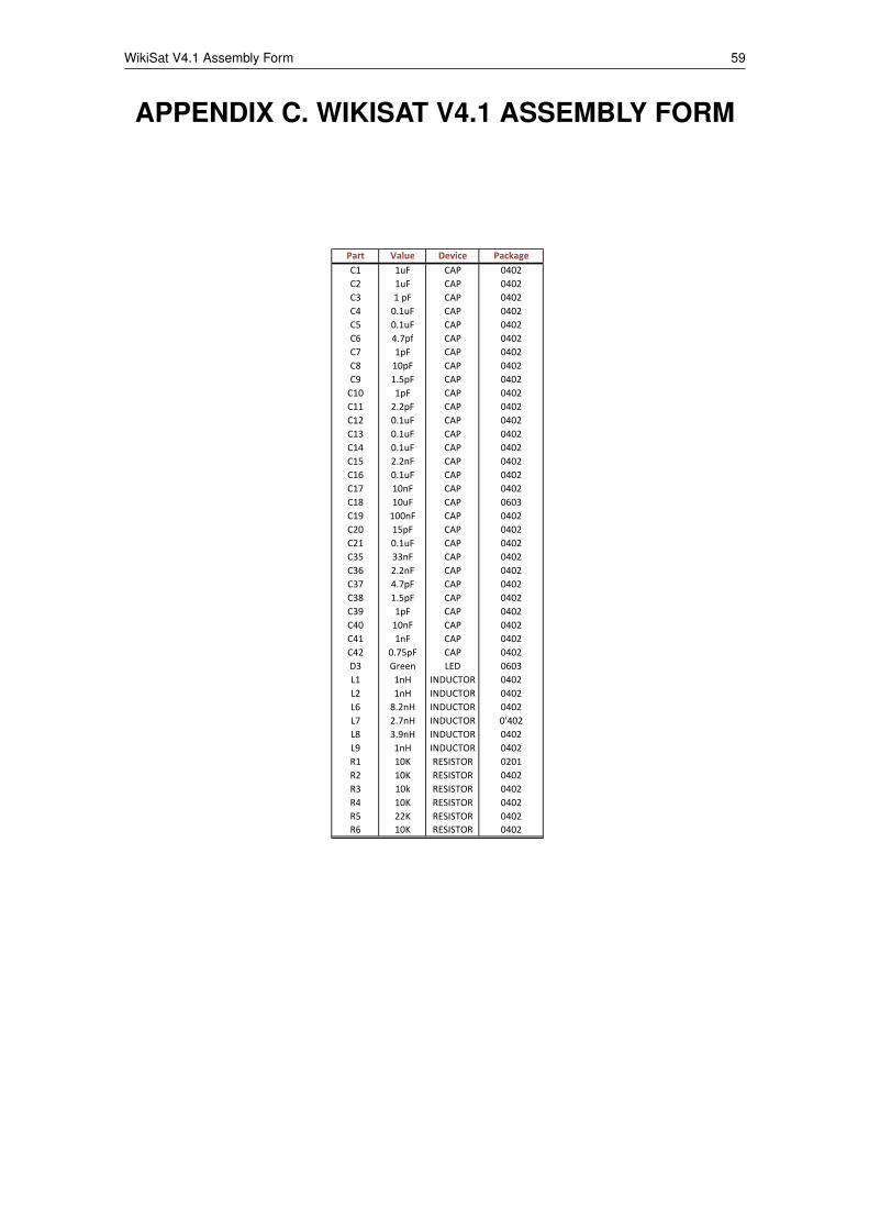
WikiSat V4.1 Assembly Form 59
APPENDIX C. WIKISAT V4.1 ASSEMBLY FORM
Part Value Device Package
C1 1uF CAP 0402
C2 1uF CAP 0402
C3 1 pF CAP 0402
C4 0.1uF CAP 0402
C5 0.1uF CAP 0402
C6 4.7pf CAP 0402
C7 1pF CAP 0402
C8 10pF CAP 0402
C9 1.5pF CAP 0402
C10 1pF CAP 0402
C11 2.2pF CAP 0402
C12 0.1uF CAP 0402
C13 0.1uF CAP 0402
C14 0.1uF CAP 0402
C15 2.2nF CAP 0402
C16 0.1uF CAP 0402
C17 10nF CAP 0402
C18 10uF CAP 0603
C19 100nF CAP 0402
C20 15pF CAP 0402
C21 0.1uF CAP 0402
C35 33nF CAP 0402
C36 2.2nF CAP 0402
C37 4.7pF CAP 0402
C38 1.5pF CAP 0402
C39 1pF CAP 0402
C40 10nF CAP 0402
C41 1nF CAP 0402
C42 0.75pF CAP 0402
D3 Green LED 0603
L1 1nH INDUCTOR 0402
L2 1nH INDUCTOR 0402
L6 8.2nH INDUCTOR 0402
L7 2.7nH INDUCTOR 0'402
L8 3.9nH INDUCTOR 0402
L9 1nH INDUCTOR 0402
R1 10K RESISTOR 0201
R2 10K RESISTOR 0402
R3 10k RESISTOR 0402
R4 10K RESISTOR 0402
R5 22K RESISTOR 0402
R6 10K RESISTOR 0402

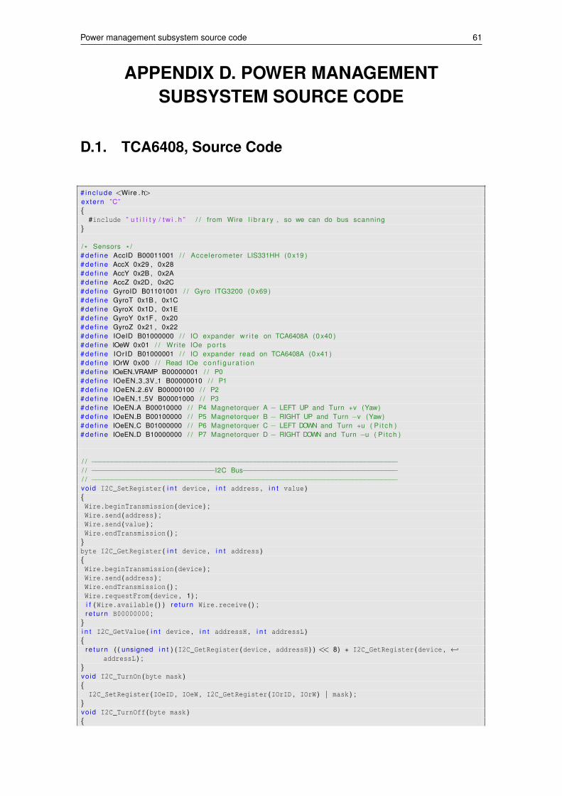
Power management subsystem source code 61
APPENDIX D. POWER MANAGEMENTSUBSYSTEM SOURCE CODE
D.1. TCA6408, Source Code
# inc lude <Wire . h>extern ”C”{
#include ” u t i l i t y / t w i . h ” / / from Wire l i b r a r y , so we can do bus scanning}
/ * Sensors * /# de f ine AccID B00011001 / / Accelerometer LIS331HH (0 x19 )# de f ine AccX 0x29 , 0x28# de f ine AccY 0x2B , 0x2A# def ine AccZ 0x2D , 0x2C# def ine GyroID B01101001 / / Gyro ITG3200 (0 x69 )# de f ine GyroT 0x1B , 0x1C# def ine GyroX 0x1D , 0x1E# def ine GyroY 0x1F , 0x20# de f ine GyroZ 0x21 , 0x22# de f ine IOeID B01000000 / / IO expander w r i t e on TCA6408A (0 x40 )# de f ine IOeW 0x01 / / Wr i te IOe por t s# de f ine IOrID B01000001 / / IO expander read on TCA6408A (0 x41 )# de f ine IOrW 0x00 / / Read IOe c o n f i g u r a t i o n# de f ine IOeEN VRAMP B00000001 / / P0# de f ine IOeEN 3 3V 1 B00000010 / / P1# de f ine IOeEN 2 6V B00000100 / / P2# de f ine IOeEN 1 5V B00001000 / / P3# de f ine IOeEN A B00010000 / / P4 Magnetorquer A − LEFT UP and Turn +v (Yaw)# de f ine IOeEN B B00100000 / / P5 Magnetorquer B − RIGHT UP and Turn −v (Yaw)# de f ine IOeEN C B01000000 / / P6 Magnetorquer C − LEFT DOWN and Turn +u ( P i t ch )# de f ine IOeEN D B10000000 / / P7 Magnetorquer D − RIGHT DOWN and Turn −u ( P i t ch )
/ / −−−−−−−−−−−−−−−−−−−−−−−−−−−−−−−−−−−−−−−−−−−−−−−−−−−−−−−−−−−−−−−−−−−−−−−−−−−/ / −−−−−−−−−−−−−−−−−−−−−−−−−−−−−−I2C Bus−−−−−−−−−−−−−−−−−−−−−−−−−−−−−−−−−−−−−−/ / −−−−−−−−−−−−−−−−−−−−−−−−−−−−−−−−−−−−−−−−−−−−−−−−−−−−−−−−−−−−−−−−−−−−−−−−−−−vo id I2C_SetRegister ( i n t device , i n t address , i n t value ){Wire . beginTransmission (device ) ;Wire . send (address ) ;Wire . send (value ) ;Wire . endTransmission ( ) ;
}byte I2C_GetRegister ( i n t device , i n t address ){Wire . beginTransmission (device ) ;Wire . send (address ) ;Wire . endTransmission ( ) ;Wire . requestFrom (device , 1) ;i f (Wire . available ( ) ) r e t u r n Wire . receive ( ) ;r e t u r n B00000000 ;
}i n t I2C_GetValue ( i n t device , i n t addressH , i n t addressL ){
r e t u r n ( ( unsigned i n t ) (I2C_GetRegister (device , addressH ) ) << 8) + I2C_GetRegister (device , ←↩addressL ) ;
}vo id I2C_TurnOn (byte mask ){
I2C_SetRegister (IOeID , IOeW , I2C_GetRegister (IOrID , IOrW ) | mask ) ;}vo id I2C_TurnOff (byte mask ){
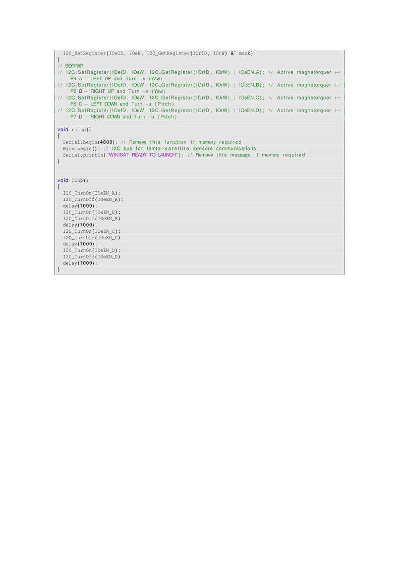
I2C_SetRegister (IOeID , IOeW , I2C_GetRegister (IOrID , IOrW ) &˜ mask ) ;}/ / BORRAR/ / I2C SetRegis ter ( IOeID , IOeW, I2C GetRegis ter ( IOrID , IOrW ) | IOeEN A ) ; / / Ac t i ve magnetorquer ←↩
P4 A − LEFT UP and Turn +v (Yaw)/ / I2C SetRegis ter ( IOeID , IOeW, I2C GetRegis ter ( IOrID , IOrW ) | IOeEN B ) ; / / Ac t i ve magnetorquer ←↩
P5 B − RIGHT UP and Turn −v (Yaw)/ / I2C SetRegis ter ( IOeID , IOeW, I2C GetRegis ter ( IOrID , IOrW ) | IOeEN C ) ; / / Ac t i ve magnetorquer ←↩
P6 C − LEFT DOWN and Turn +u ( P i t ch )/ / I2C SetRegis ter ( IOeID , IOeW, I2C GetRegis ter ( IOrID , IOrW ) | IOeEN D ) ; / / Ac t i ve magnetorquer ←↩
P7 D − RIGHT DOWN and Turn −u ( P i t ch )
vo id setup ( ){
Serial . begin (4800) ; / / Remove t h i s f u n c t i o n i f memory requ i redWire . begin ( ) ; / / I2C bus f o r femto−s a t e l l i t e sensors communicationsSerial . println ( ” WIKISAT READY TO LAUNCH” ) ; / / Remove t h i s message i f memory requ i red
}
vo id loop ( ){
I2C_TurnOn (IOeEN_A ) ;I2C_TurnOff (IOeEN_A ) ;delay (1000) ;I2C_TurnOn (IOeEN_B ) ;I2C_TurnOff (IOeEN_B )delay (1000) ;I2C_TurnOn (IOeEN_C ) ;I2C_TurnOff (IOeEN_C )delay (1000) ;I2C_TurnOn (IOeEN_D ) ;I2C_TurnOff (IOeEN_D )delay (1000) ;
}
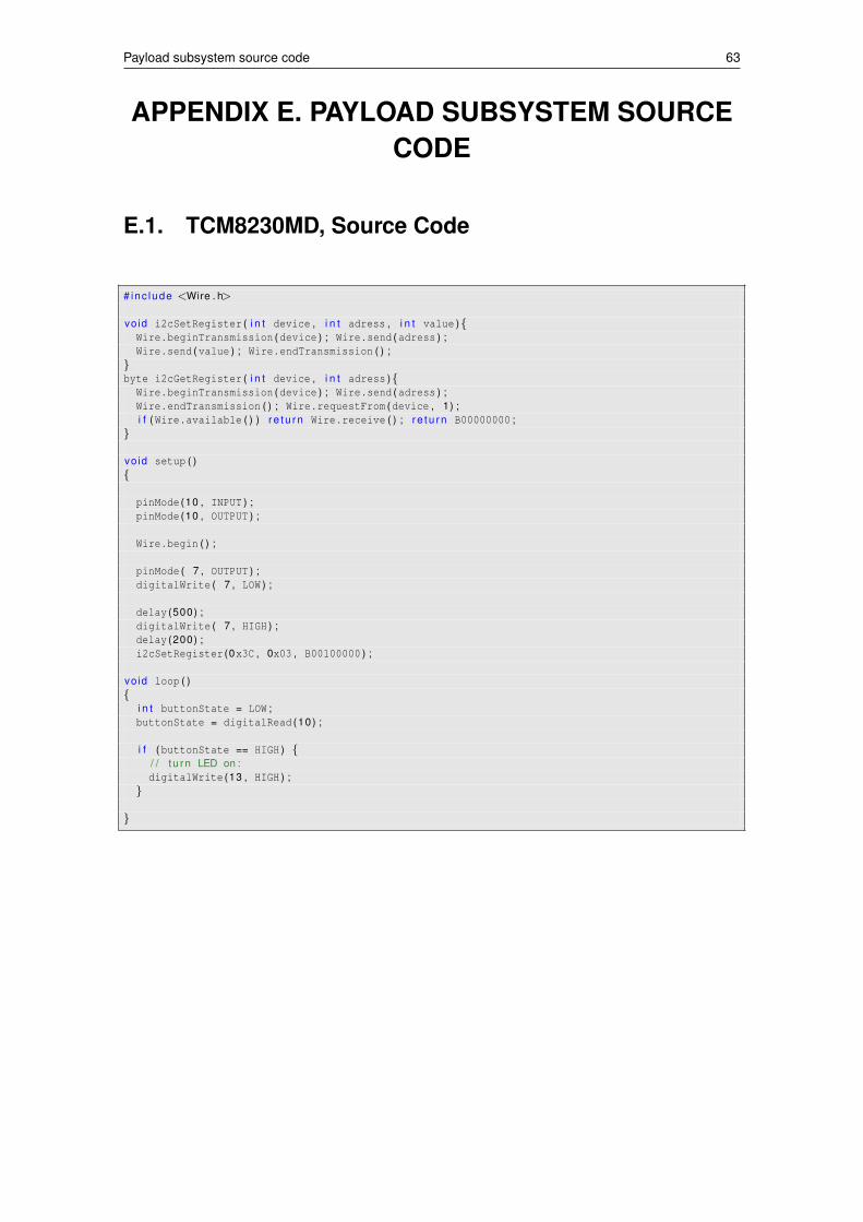
Payload subsystem source code 63
APPENDIX E. PAYLOAD SUBSYSTEM SOURCECODE
E.1. TCM8230MD, Source Code
# inc lude <Wire . h>
vo id i2cSetRegister ( i n t device , i n t adress , i n t value ){Wire . beginTransmission (device ) ; Wire . send (adress ) ;Wire . send (value ) ; Wire . endTransmission ( ) ;
}byte i2cGetRegister ( i n t device , i n t adress ){
Wire . beginTransmission (device ) ; Wire . send (adress ) ;Wire . endTransmission ( ) ; Wire . requestFrom (device , 1) ;i f (Wire . available ( ) ) r e t u r n Wire . receive ( ) ; r e t u r n B00000000 ;
}
vo id setup ( ){
pinMode (10 , INPUT ) ;pinMode (10 , OUTPUT ) ;
Wire . begin ( ) ;
pinMode ( 7 , OUTPUT ) ;digitalWrite ( 7 , LOW ) ;
delay (500) ;digitalWrite ( 7 , HIGH ) ;delay (200) ;i2cSetRegister (0x3C , 0x03 , B00100000 ) ;
vo id loop ( ){
i n t buttonState = LOW ;buttonState = digitalRead (10) ;
i f (buttonState == HIGH ) {/ / t u rn LED on :digitalWrite (13 , HIGH ) ;
}
}
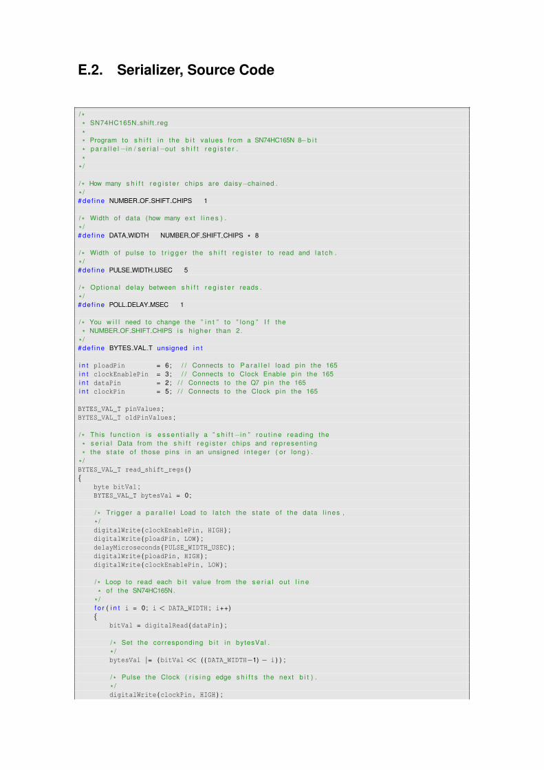
E.2. Serializer, Source Code
/ ** SN74HC165N shift reg
** Program to s h i f t i n the b i t values from a SN74HC165N 8−b i t
* p a r a l l e l−i n / s e r i a l−out s h i f t r e g i s t e r .
** /
/ * How many s h i f t r e g i s t e r ch ips are daisy−chained .
* /# de f ine NUMBER OF SHIFT CHIPS 1
/ * Width o f data (how many ext l i n e s ) .
* /# de f ine DATA WIDTH NUMBER OF SHIFT CHIPS * 8
/ * Width o f pulse to t r i g g e r the s h i f t r e g i s t e r to read and l a t c h .
* /# de f ine PULSE WIDTH USEC 5
/ * Opt iona l delay between s h i f t r e g i s t e r reads .
* /# de f ine POLL DELAY MSEC 1
/ * You w i l l need to change the ” i n t ” to ” long ” I f the
* NUMBER OF SHIFT CHIPS i s h igher than 2.
* /# de f ine BYTES VAL T unsigned i n t
i n t ploadPin = 6; / / Connects to P a r a l l e l load p in the 165i n t clockEnablePin = 3; / / Connects to Clock Enable p in the 165i n t dataPin = 2; / / Connects to the Q7 pin the 165i n t clockPin = 5; / / Connects to the Clock p in the 165
BYTES_VAL_T pinValues ;BYTES_VAL_T oldPinValues ;
/ * This f u n c t i o n i s e s s e n t i a l l y a ” s h i f t−i n ” r o u t i n e reading the
* s e r i a l Data from the s h i f t r e g i s t e r ch ips and represen t ing
* the s ta te o f those pins i n an unsigned i n t e g e r ( or long ) .
* /BYTES_VAL_T read_shift_regs ( ){
byte bitVal ;BYTES_VAL_T bytesVal = 0;
/ * Tr igger a p a r a l l e l Load to l a t c h the s ta te o f the data l i nes ,
* /digitalWrite (clockEnablePin , HIGH ) ;digitalWrite (ploadPin , LOW ) ;delayMicroseconds (PULSE_WIDTH_USEC ) ;digitalWrite (ploadPin , HIGH ) ;digitalWrite (clockEnablePin , LOW ) ;
/ * Loop to read each b i t value from the s e r i a l out l i n e
* of the SN74HC165N.
* /f o r ( i n t i = 0; i < DATA_WIDTH ; i++){
bitVal = digitalRead (dataPin ) ;
/ * Set the corresponding b i t i n bytesVal .
* /bytesVal |= (bitVal << ( ( DATA_WIDTH−1) − i ) ) ;
/ * Pulse the Clock ( r i s i n g edge s h i f t s the next b i t ) .
* /digitalWrite (clockPin , HIGH ) ;
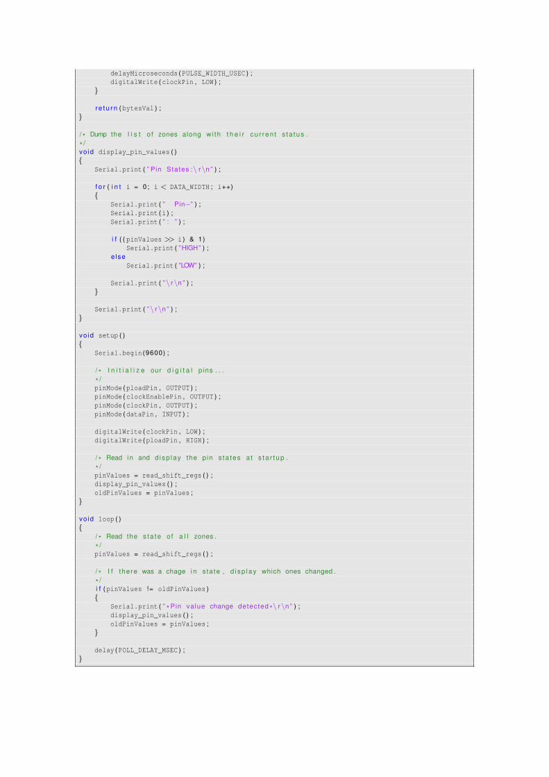
delayMicroseconds (PULSE_WIDTH_USEC ) ;digitalWrite (clockPin , LOW ) ;
}
r e t u r n (bytesVal ) ;}
/ * Dump the l i s t o f zones along wi th t h e i r cu r ren t s ta tus .
* /vo id display_pin_values ( ){
Serial . print ( ” Pin States :\ r\n ” ) ;
f o r ( i n t i = 0; i < DATA_WIDTH ; i++){
Serial . print ( ” Pin−” ) ;Serial . print (i ) ;Serial . print ( ” : ” ) ;
i f ( ( pinValues >> i ) & 1)Serial . print ( ”HIGH” ) ;
e lseSerial . print ( ”LOW” ) ;
Serial . print ( ”\ r\n ” ) ;}
Serial . print ( ”\ r\n ” ) ;}
vo id setup ( ){
Serial . begin (9600) ;
/ * I n i t i a l i z e our d i g i t a l p ins . . .
* /pinMode (ploadPin , OUTPUT ) ;pinMode (clockEnablePin , OUTPUT ) ;pinMode (clockPin , OUTPUT ) ;pinMode (dataPin , INPUT ) ;
digitalWrite (clockPin , LOW ) ;digitalWrite (ploadPin , HIGH ) ;
/ * Read i n and d i sp lay the p in s ta tes a t s t a r t u p .
* /pinValues = read_shift_regs ( ) ;display_pin_values ( ) ;oldPinValues = pinValues ;
}
vo id loop ( ){
/ * Read the s ta te o f a l l zones .
* /pinValues = read_shift_regs ( ) ;
/ * I f there was a chage i n s ta te , d i sp lay which ones changed .
* /i f (pinValues != oldPinValues ){
Serial . print ( ” * Pin value change detected *\ r\n ” ) ;display_pin_values ( ) ;oldPinValues = pinValues ;
}
delay (POLL_DELAY_MSEC ) ;}
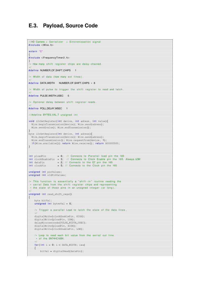
E.3. Payload, Source Code
/ /HD Camera + S e r i a l i z e r + S inc ron i zaa t i on s i g n a l# inc lude <Wire . h>
extern ”C”{# inc lude <FrequencyTimer2 . h>}/ * How many s h i f t r e g i s t e r ch ips are daisy−chained .
* /# de f ine NUMBER OF SHIFT CHIPS 1
/ * Width o f data (how many ext l i n e s ) .
* /# de f ine DATA WIDTH NUMBER OF SHIFT CHIPS * 8
/ * Width o f pulse to t r i g g e r the s h i f t r e g i s t e r to read and l a t c h .
* /# de f ine PULSE WIDTH USEC 5
/ * Opt iona l delay between s h i f t r e g i s t e r reads .
* /# de f ine POLL DELAY MSEC 1
/ / # de f ine BYTES VAL T unsigned i n t
vo id i2cSetRegister ( i n t device , i n t adress , i n t value ){Wire . beginTransmission (device ) ; Wire . send (adress ) ;Wire . send (value ) ; Wire . endTransmission ( ) ;
}byte i2cGetRegister ( i n t device , i n t adress ){
Wire . beginTransmission (device ) ; Wire . send (adress ) ;Wire . endTransmission ( ) ; Wire . requestFrom (device , 1) ;i f (Wire . available ( ) ) r e t u r n Wire . receive ( ) ; r e t u r n B00000000 ;
}
i n t ploadPin = 6; / / Connects to P a r a l l e l load p in the 165i n t clockEnablePin = 3; / / Connects to Clock Enable p in the 165. Always LOWi n t dataPin = 2; / / Connects to the Q7 pin the 165i n t clockPin = 5; / / Connects to the Clock p in the 165
unsigned i n t pinValues ;unsigned i n t oldPinValues ;
/ * This f u n c t i o n i s e s s e n t i a l l y a ” s h i f t−i n ” r o u t i n e reading the
* s e r i a l Data from the s h i f t r e g i s t e r ch ips and represen t ing
* the s ta te o f those pins i n an unsigned i n t e g e r ( or long ) .
* /unsigned i n t read_shift_regs ( ){
byte bitVal ;unsigned i n t bytesVal = 0;
/ * Tr igger a p a r a l l e l Load to l a t c h the s ta te o f the data l i nes ,
* /digitalWrite (clockEnablePin , HIGH ) ;digitalWrite (ploadPin , LOW ) ;delayMicroseconds (PULSE_WIDTH_USEC ) ;digitalWrite (ploadPin , HIGH ) ;digitalWrite (clockEnablePin , LOW ) ;
/ * Loop to read each b i t value from the s e r i a l out l i n e
* of the SN74HC165N.
* /f o r ( i n t i = 0; i < DATA_WIDTH ; i++){
bitVal = digitalRead (dataPin ) ;
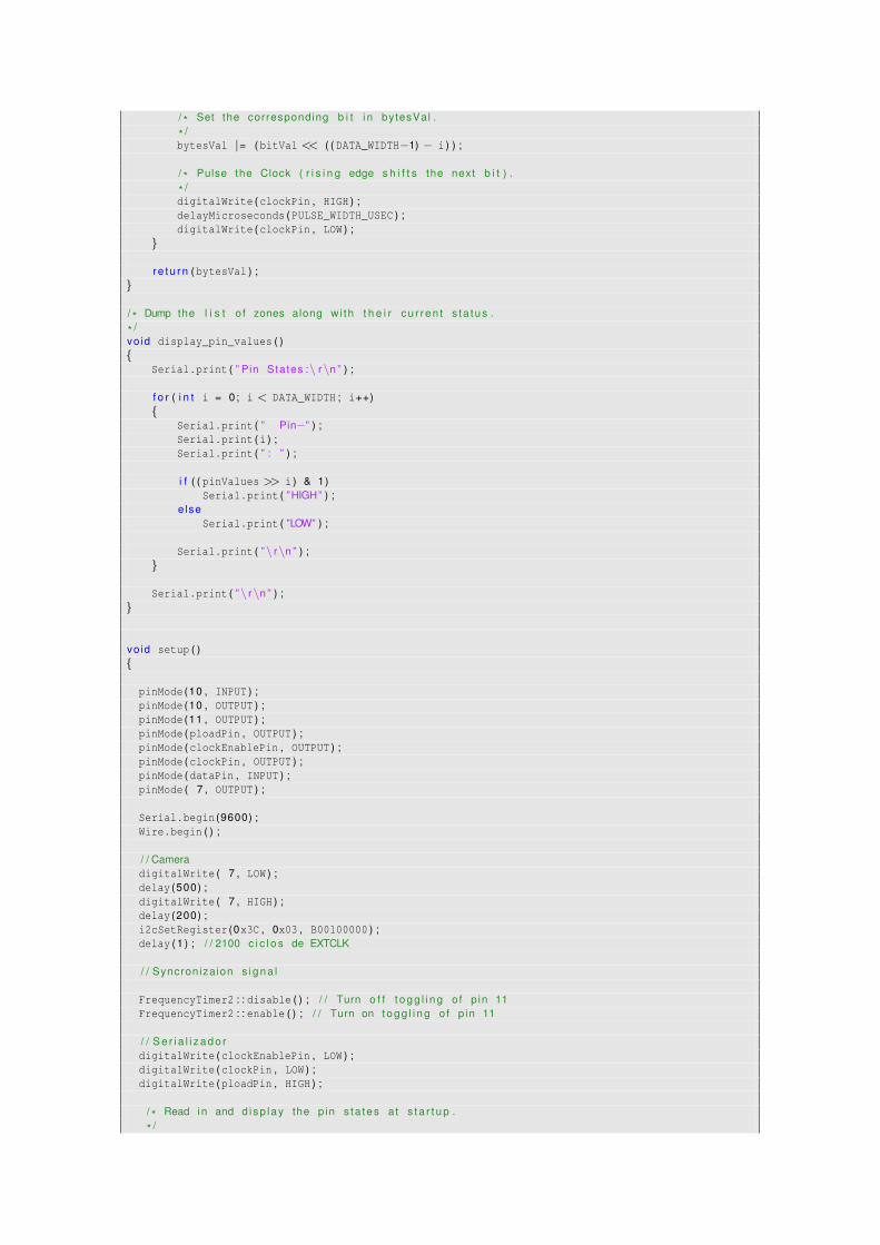
/ * Set the corresponding b i t i n bytesVal .
* /bytesVal |= (bitVal << ( ( DATA_WIDTH−1) − i ) ) ;
/ * Pulse the Clock ( r i s i n g edge s h i f t s the next b i t ) .
* /digitalWrite (clockPin , HIGH ) ;delayMicroseconds (PULSE_WIDTH_USEC ) ;digitalWrite (clockPin , LOW ) ;
}
r e t u r n (bytesVal ) ;}
/ * Dump the l i s t o f zones along wi th t h e i r cu r ren t s ta tus .
* /vo id display_pin_values ( ){
Serial . print ( ” Pin States :\ r\n ” ) ;
f o r ( i n t i = 0; i < DATA_WIDTH ; i++){
Serial . print ( ” Pin−” ) ;Serial . print (i ) ;Serial . print ( ” : ” ) ;
i f ( ( pinValues >> i ) & 1)Serial . print ( ”HIGH” ) ;
e lseSerial . print ( ”LOW” ) ;
Serial . print ( ”\ r\n ” ) ;}
Serial . print ( ”\ r\n ” ) ;}
vo id setup ( ){
pinMode (10 , INPUT ) ;pinMode (10 , OUTPUT ) ;pinMode (11 , OUTPUT ) ;pinMode (ploadPin , OUTPUT ) ;pinMode (clockEnablePin , OUTPUT ) ;pinMode (clockPin , OUTPUT ) ;pinMode (dataPin , INPUT ) ;pinMode ( 7 , OUTPUT ) ;
Serial . begin (9600) ;Wire . begin ( ) ;
/ / CameradigitalWrite ( 7 , LOW ) ;delay (500) ;digitalWrite ( 7 , HIGH ) ;delay (200) ;i2cSetRegister (0x3C , 0x03 , B00100000 ) ;delay ( 1 ) ; / / 2100 c i c l o s de EXTCLK
/ / Syncroniza ion s i g n a l
FrequencyTimer2 : : disable ( ) ; / / Turn o f f t o g g l i n g o f p in 11FrequencyTimer2 : : enable ( ) ; / / Turn on t o g g l i n g o f p in 11
/ / S e r i a l i z a d o rdigitalWrite (clockEnablePin , LOW ) ;digitalWrite (clockPin , LOW ) ;digitalWrite (ploadPin , HIGH ) ;
/ * Read i n and d i sp lay the p in s ta tes a t s t a r t u p .
* /

pinValues = read_shift_regs ( ) ;display_pin_values ( ) ;oldPinValues = pinValues ;
}
vo id loop ( ){
delay (POLL_DELAY_MSEC ) ;
}
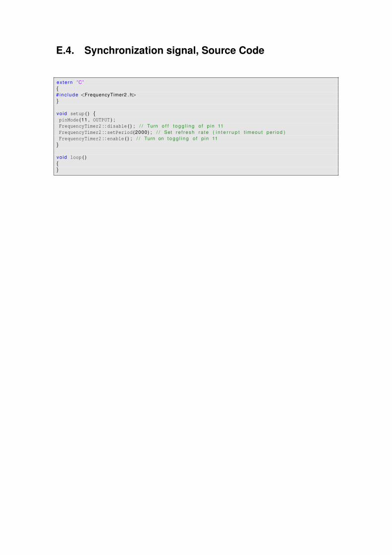
E.4. Synchronization signal, Source Code
extern ”C”{# inc lude <FrequencyTimer2 . h>}
vo id setup ( ) {pinMode (11 , OUTPUT ) ;FrequencyTimer2 : : disable ( ) ; / / Turn o f f t o g g l i n g o f p in 11FrequencyTimer2 : : setPeriod (2000) ; / / Set re f resh ra te ( i n t e r r u p t t imeout per iod )FrequencyTimer2 : : enable ( ) ; / / Turn on t o g g l i n g o f p in 11
}
vo id loop ( ){}

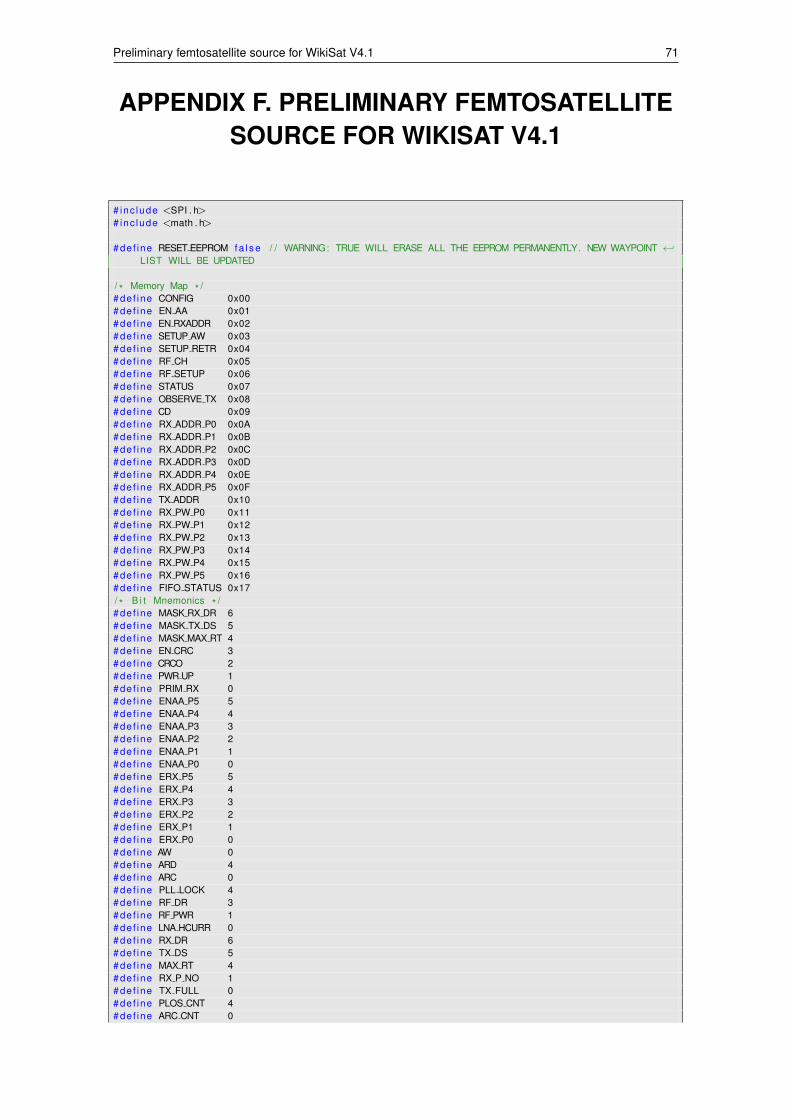
Preliminary femtosatellite source for WikiSat V4.1 71
APPENDIX F. PRELIMINARY FEMTOSATELLITESOURCE FOR WIKISAT V4.1
# inc lude <SPI . h># inc lude <math . h>
# def ine RESET EEPROM f a l s e / / WARNING: TRUE WILL ERASE ALL THE EEPROM PERMANENTLY. NEW WAYPOINT ←↩LIST WILL BE UPDATED
/ * Memory Map * /# de f ine CONFIG 0x00# def ine EN AA 0x01# def ine EN RXADDR 0x02# def ine SETUP AW 0x03# def ine SETUP RETR 0x04# def ine RF CH 0x05# def ine RF SETUP 0x06# def ine STATUS 0x07# def ine OBSERVE TX 0x08# def ine CD 0x09# def ine RX ADDR P0 0x0A# def ine RX ADDR P1 0x0B# def ine RX ADDR P2 0x0C# def ine RX ADDR P3 0x0D# def ine RX ADDR P4 0x0E# def ine RX ADDR P5 0x0F# def ine TX ADDR 0x10# def ine RX PW P0 0x11# def ine RX PW P1 0x12# def ine RX PW P2 0x13# def ine RX PW P3 0x14# def ine RX PW P4 0x15# def ine RX PW P5 0x16# def ine FIFO STATUS 0x17/ * B i t Mnemonics * /# de f ine MASK RX DR 6# def ine MASK TX DS 5# def ine MASK MAX RT 4# def ine EN CRC 3# def ine CRCO 2# def ine PWR UP 1# def ine PRIM RX 0# def ine ENAA P5 5# def ine ENAA P4 4# def ine ENAA P3 3# def ine ENAA P2 2# def ine ENAA P1 1# def ine ENAA P0 0# def ine ERX P5 5# def ine ERX P4 4# def ine ERX P3 3# def ine ERX P2 2# def ine ERX P1 1# def ine ERX P0 0# def ine AW 0# def ine ARD 4# def ine ARC 0# def ine PLL LOCK 4# def ine RF DR 3# def ine RF PWR 1# def ine LNA HCURR 0# def ine RX DR 6# def ine TX DS 5# def ine MAX RT 4# def ine RX P NO 1# def ine TX FULL 0# def ine PLOS CNT 4# def ine ARC CNT 0
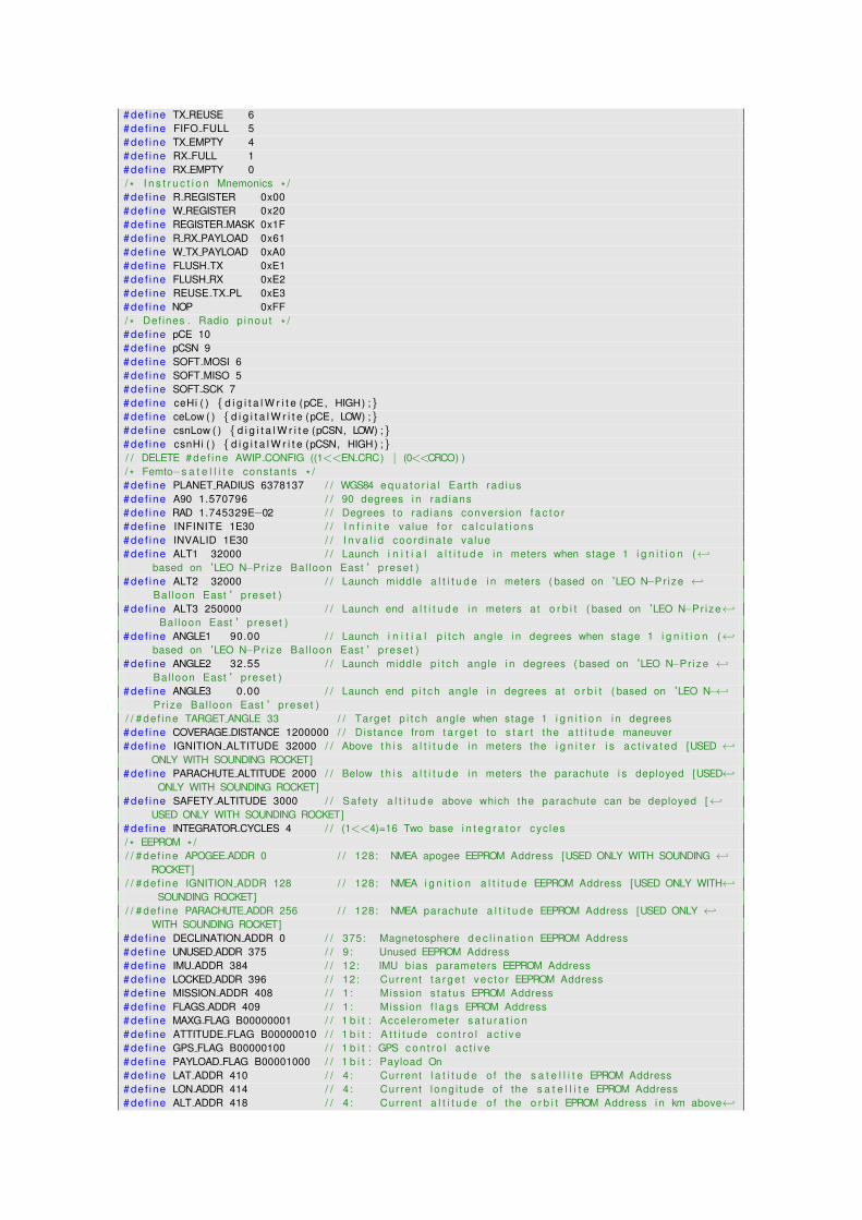
# def ine TX REUSE 6# def ine FIFO FULL 5# def ine TX EMPTY 4# def ine RX FULL 1# def ine RX EMPTY 0/ * I n s t r u c t i o n Mnemonics * /# de f ine R REGISTER 0x00# def ine W REGISTER 0x20# def ine REGISTER MASK 0x1F# def ine R RX PAYLOAD 0x61# def ine W TX PAYLOAD 0xA0# def ine FLUSH TX 0xE1# def ine FLUSH RX 0xE2# def ine REUSE TX PL 0xE3# def ine NOP 0xFF/ * Defines . Radio p inou t * /# de f ine pCE 10# def ine pCSN 9# def ine SOFT MOSI 6# de f ine SOFT MISO 5# def ine SOFT SCK 7# def ine ceHi ( ) { d i g i t a l W r i t e (pCE, HIGH) ;}# def ine ceLow ( ) { d i g i t a l W r i t e (pCE, LOW) ;}# def ine csnLow ( ) { d i g i t a l W r i t e (pCSN, LOW) ;}# def ine csnHi ( ) { d i g i t a l W r i t e (pCSN, HIGH) ;}/ / DELETE # def ine AWIP CONFIG ((1<<EN CRC) | (0<<CRCO) )/ * Femto−s a t e l l i t e constants * /# de f ine PLANET RADIUS 6378137 / / WGS84 e q u a t o r i a l Earth rad ius# de f ine A90 1.570796 / / 90 degrees i n rad ians# de f ine RAD 1.745329E−02 / / Degrees to rad ians convers ion f a c t o r# de f ine INFINITE 1E30 / / I n f i n i t e value f o r c a l c u l a t i o n s# de f ine INVALID 1E30 / / I n v a l i d coord ina te value# de f ine ALT1 32000 / / Launch i n i t i a l a l t i t u d e i n meters when stage 1 i g n i t i o n (←↩
based on 'LEO N−Pr ize Bal loon East ' preset )# de f ine ALT2 32000 / / Launch middle a l t i t u d e i n meters ( based on 'LEO N−Pr ize ←↩
Bal loon East ' preset )# de f ine ALT3 250000 / / Launch end a l t i t u d e i n meters a t o r b i t ( based on 'LEO N−Pr ize←↩
Bal loon East ' preset )# de f ine ANGLE1 90.00 / / Launch i n i t i a l p i t c h angle i n degrees when stage 1 i g n i t i o n (←↩
based on 'LEO N−Pr ize Bal loon East ' preset )# de f ine ANGLE2 32.55 / / Launch middle p i t c h angle i n degrees ( based on 'LEO N−Pr ize ←↩
Bal loon East ' preset )# de f ine ANGLE3 0.00 / / Launch end p i t c h angle i n degrees a t o r b i t ( based on 'LEO N−←↩
Pr ize Bal loon East ' preset )/ / # de f ine TARGET ANGLE 33 / / Target p i t c h angle when stage 1 i g n i t i o n i n degrees# de f ine COVERAGE DISTANCE 1200000 / / Distance from t a r g e t to s t a r t the a t t i t u d e maneuver# de f ine IGNITION ALTITUDE 32000 / / Above t h i s a l t i t u d e i n meters the i g n i t e r i s a c t i v a t e d [USED ←↩
ONLY WITH SOUNDING ROCKET]# de f ine PARACHUTE ALTITUDE 2000 / / Below t h i s a l t i t u d e i n meters the parachute i s deployed [USED←↩
ONLY WITH SOUNDING ROCKET]# de f ine SAFETY ALTITUDE 3000 / / Safety a l t i t u d e above which the parachute can be deployed [←↩
USED ONLY WITH SOUNDING ROCKET]# de f ine INTEGRATOR CYCLES 4 / / (1<<4)=16 Two base i n t e g r a t o r cyc les/ * EEPROM * // / # de f ine APOGEE ADDR 0 / / 128: NMEA apogee EEPROM Address [USED ONLY WITH SOUNDING ←↩
ROCKET]/ / # de f ine IGNITION ADDR 128 / / 128: NMEA i g n i t i o n a l t i t u d e EEPROM Address [USED ONLY WITH←↩
SOUNDING ROCKET]/ / # de f ine PARACHUTE ADDR 256 / / 128: NMEA parachute a l t i t u d e EEPROM Address [USED ONLY ←↩
WITH SOUNDING ROCKET]# de f ine DECLINATION ADDR 0 / / 375: Magnetosphere d e c l i n a t i o n EEPROM Address# de f ine UNUSED ADDR 375 / / 9 : Unused EEPROM Address# de f ine IMU ADDR 384 / / 12: IMU bias parameters EEPROM Address# de f ine LOCKED ADDR 396 / / 12: Current t a r g e t vec to r EEPROM Address# de f ine MISSION ADDR 408 / / 1 : Mission s ta tus EPROM Address# de f ine FLAGS ADDR 409 / / 1 : Mission f l a g s EPROM Address# de f ine MAXG FLAG B00000001 / / 1 b i t : Accelerometer s a t u r a t i o n# de f ine ATTITUDE FLAG B00000010 / / 1 b i t : A t t i t u d e c o n t r o l a c t i v e# de f ine GPS FLAG B00000100 / / 1 b i t : GPS c o n t r o l a c t i v e# de f ine PAYLOAD FLAG B00001000 / / 1 b i t : Payload On# def ine LAT ADDR 410 / / 4 : Current l a t i t u d e of the s a t e l l i t e EPROM Address# de f ine LON ADDR 414 / / 4 : Current l ong i t ude of the s a t e l l i t e EPROM Address# de f ine ALT ADDR 418 / / 4 : Current a l t i t u d e of the o r b i t EPROM Address i n km above←↩
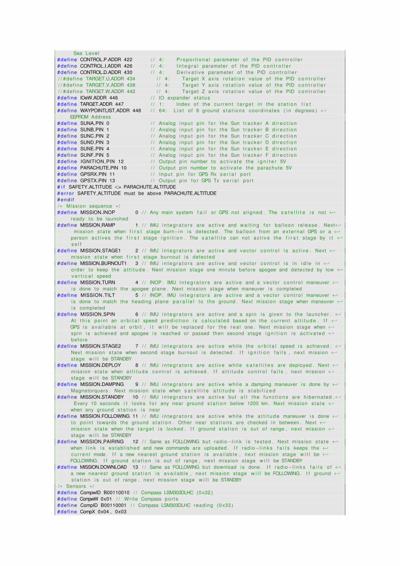
Sea Level# de f ine CONTROL P ADDR 422 / / 4 : P r opo r t i o na l parameter o f the PID c o n t r o l l e r# de f ine CONTROL I ADDR 426 / / 4 : I n t e g r a l parameter o f the PID c o n t r o l l e r# de f ine CONTROL D ADDR 430 / / 4 : D e r i v a t i v e parameter o f the PID c o n t r o l l e r/ / # de f ine TARGET U ADDR 434 / / 4 : Target X ax is r o t a t i o n value o f the PID c o n t r o l l e r/ / # de f ine TARGET V ADDR 438 / / 4 : Target Y ax is r o t a t i o n value o f the PID c o n t r o l l e r/ / # de f ine TARGET W ADDR 442 / / 4 : Target Z ax is r o t a t i o n value o f the PID c o n t r o l l e r# de f ine IOeW ADDR 446 / / IO expander s ta tus# de f ine TARGET ADDR 447 / / 1 : Index o f the cu r ren t t a r g e t i n the s t a t i o n l i s t# de f ine WAYPOINTLIST ADDR 448 / / 64: L i s t o f 8 ground s t a t i o n s coord ina tes ( i n degrees ) ←↩
EEPROM Address# de f ine SUNA PIN 0 / / Analog i npu t p in f o r the Sun t r a c k e r A d i r e c t i o n# de f ine SUNB PIN 1 / / Analog i npu t p in f o r the Sun t r a c k e r B d i r e c t i o n# de f ine SUNC PIN 2 / / Analog inpu t p in f o r the Sun t r a c k e r C d i r e c t i o n# de f ine SUND PIN 3 / / Analog inpu t p in f o r the Sun t r a c k e r D d i r e c t i o n# de f ine SUNE PIN 4 / / Analog i npu t p in f o r the Sun t r a c k e r E d i r e c t i o n# de f ine SUNF PIN 5 / / Analog inpu t p in f o r the Sun t r a c k e r F d i r e c t i o n# de f ine IGNITION PIN 12 / / Output p in number to a c t i v a t e the i g n i t e r 5V# def ine PARACHUTE PIN 10 / / Output p in number to a c t i v a t e the parachute 5V# def ine GPSRX PIN 11 / / Inpu t p in f o r GPS Rx s e r i a l po r t# de f ine GPSTX PIN 13 / / Output p in f o r GPS Tx s e r i a l po r t# i f SAFETY ALTITUDE <= PARACHUTE ALTITUDE# e r r o r SAFETY ALTITUDE must be above PARACHUTE ALTITUDE# end i f/ * Mission sequence * /# de f ine MISSION INOP 0 / / Any main system f a i l or GPS not a l igned . The s a t e l l i t e i s not ←↩
ready to be launched# def ine MISSION RAMP 1 / / IMU i n t e g r a t o r s are a c t i v e and wa i t i ng f o r ba l loon re lease . Next←↩
mission s ta te when f i r s t stage burn−i n i s detected . The ba l loon from an ex te rna l GPS or a ←↩person ac t i ves the f i r s t stage i g n i t i o n . The s a t e l l i t e can not a c t i v e the f i r s t stage by i t ←↩s e l f
# de f ine MISSION STAGE1 2 / / IMU i n t e g r a t o r s are a c t i v e and vec to r c o n t r o l i s a c t i v e . Next ←↩mission s ta te when f i r s t stage burnout i s detected
# de f ine MISSION BURNOUT1 3 / / IMU i n t e g r a t o r s are a c t i v e and vec to r c o n t r o l i s i n i d l e i n ←↩order to keep the a t t i t u d e . Next mission stage one minute before apogee and detected by low ←↩v e r t i c a l speed
# de f ine MISSION TURN 4 / / INOP . IMU i n t e g r a t o r s are a c t i v e and a vec to r c o n t r o l maneuver ←↩i s done to match the apogee plane . Next mission stage when maneuver i s completed
# de f ine MISSION TILT 5 / / INOP . IMU i n t e g r a t o r s are a c t i v e and a vec to r c o n t r o l maneuver ←↩i s done to match the heading plane p a r a l l e l to the ground . Next mission stage when maneuver ←↩i s completed
# de f ine MISSION SPIN 6 / / IMU i n t e g r a t o r s are a c t i v e and a spin i s given to the launcher . ←↩At t h i s po in t an o r b i t a l speed p r e d i c t i o n i s ca l cu la ted based on the cu r ren t a l t i t u d e . I f ←↩GPS i s a v a i l a b l e a t o r b i t , i t w i l l be replaced f o r the r e a l one . Next mission stage when ←↩sp in i s achieved and apogee i s reached or passed then second stage i g n i t i o n i s a c t i v a te d ←↩before
# de f ine MISSION STAGE2 7 / / IMU i n t e g r a t o r s are a c t i v e whi le the o r b i t a l speed i s achieved . ←↩Next mission s ta te when second stage burnout i s detected . I f i g n i t i o n f a i l s , next mission ←↩stage w i l l be STANDBY
# def ine MISSION DEPLOY 8 / / IMU i n t e g r a t o r s are a c t i v e whi le s a t e l l i t e s are deployed . Next ←↩mission s ta te when a t t i t u d e c o n t r o l i s achieved . I f a t t i t u d e c o n t r o l f a i l s , next mission ←↩stage w i l l be STANDBY
# def ine MISSION DAMPING 9 / / IMU i n t e g r a t o r s are a c t i v e wh i le a damping maneuver i s done by ←↩Magnetorquers . Next mission s ta te when s a t e l l i t e a t t i t u d e i s s t a b i l i z e d
# de f ine MISSION STANDBY 10 / / IMU i n t e g r a t o r s are a c t i v e but a l l the f u n c t i o n s are h ibernated .←↩Every 10 seconds i t looks f o r any near ground s t a t i o n below 1200 km. Next mission s ta te ←↩
when any ground s t a t i o n i s near# de f ine MISSION FOLLOWING 11 / / IMU i n t e g r a t o r s are a c t i v e whi le the a t t i t u d e maneuver i s done ←↩
to po in t towards the ground s t a t i o n . Other near s t a t i o n s are checked i n between . Next ←↩mission s ta te when the t a r g e t i s locked . I f ground s t a t i o n i s out o f range , next mission ←↩stage w i l l be STANDBY
# def ine MISSION PAIRING 12 / / Same as FOLLOWING but rad io−l i n k i s tes ted . Next mission s ta te ←↩when l i n k i s es tab l i shed and new commands are uploaded . I f rad io−l i n k s f a i l s keeps the ←↩cu r ren t mode . I f a new nearest ground s t a t i o n i s ava i l ab le , next mission stage w i l l be ←↩FOLLOWING. I f ground s t a t i o n i s out o f range , next mission stage w i l l be STANDBY
# def ine MISSION DOWNLOAD 13 / / Same as FOLLOWING but download i s done . I f rad io−l i n k s f a i l s o f ←↩a new nearest ground s t a t i o n i s ava i l ab le , next mission stage w i l l be FOLLOWING. I f ground ←↩s t a t i o n i s out o f range , next mission stage w i l l be STANDBY
/ * Sensors * /# de f ine CompwID B00110010 / / Compass LSM303DLHC (0 x32 )# de f ine CompwW 0x01 / / Wr i te Compass por t s# de f ine CompID B00110001 / / Compass LSM303DLHC reading (0 x33 )# de f ine CompX 0x04 , 0x03
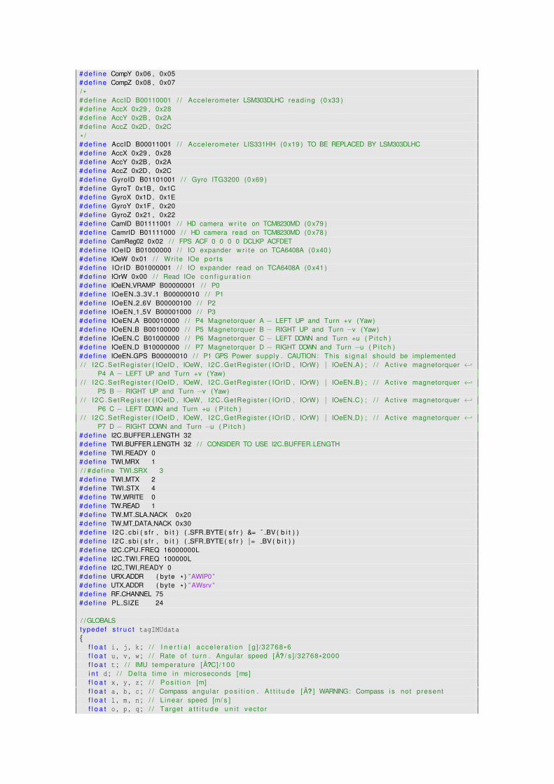
# def ine CompY 0x06 , 0x05# de f ine CompZ 0x08 , 0x07/ *# def ine AccID B00110001 / / Accelerometer LSM303DLHC reading (0 x33 )# de f ine AccX 0x29 , 0x28# de f ine AccY 0x2B , 0x2A# def ine AccZ 0x2D , 0x2C
* /# de f ine AccID B00011001 / / Accelerometer LIS331HH (0 x19 ) TO BE REPLACED BY LSM303DLHC# def ine AccX 0x29 , 0x28# de f ine AccY 0x2B , 0x2A# def ine AccZ 0x2D , 0x2C# def ine GyroID B01101001 / / Gyro ITG3200 (0 x69 )# de f ine GyroT 0x1B , 0x1C# def ine GyroX 0x1D , 0x1E# def ine GyroY 0x1F , 0x20# de f ine GyroZ 0x21 , 0x22# de f ine CamID B01111001 / / HD camera w r i t e on TCM8230MD (0 x79 )# de f ine CamrID B01111000 / / HD camera read on TCM8230MD (0 x78 )# de f ine CamReg02 0x02 / / FPS ACF 0 0 0 0 DCLKP ACFDET# def ine IOeID B01000000 / / IO expander w r i t e on TCA6408A (0 x40 )# de f ine IOeW 0x01 / / Wr i te IOe por t s# de f ine IOrID B01000001 / / IO expander read on TCA6408A (0 x41 )# de f ine IOrW 0x00 / / Read IOe c o n f i g u r a t i o n# de f ine IOeEN VRAMP B00000001 / / P0# de f ine IOeEN 3 3V 1 B00000010 / / P1# de f ine IOeEN 2 6V B00000100 / / P2# de f ine IOeEN 1 5V B00001000 / / P3# de f ine IOeEN A B00010000 / / P4 Magnetorquer A − LEFT UP and Turn +v (Yaw)# de f ine IOeEN B B00100000 / / P5 Magnetorquer B − RIGHT UP and Turn −v (Yaw)# de f ine IOeEN C B01000000 / / P6 Magnetorquer C − LEFT DOWN and Turn +u ( P i t ch )# de f ine IOeEN D B10000000 / / P7 Magnetorquer D − RIGHT DOWN and Turn −u ( P i t ch )# de f ine IOeEN GPS B00000010 / / P1 GPS Power supply . CAUTION: This s i g n a l should be implemented/ / I2C SetRegis ter ( IOeID , IOeW, I2C GetRegis ter ( IOrID , IOrW ) | IOeEN A ) ; / / Ac t i ve magnetorquer ←↩
P4 A − LEFT UP and Turn +v (Yaw)/ / I2C SetRegis ter ( IOeID , IOeW, I2C GetRegis ter ( IOrID , IOrW ) | IOeEN B ) ; / / Ac t i ve magnetorquer ←↩
P5 B − RIGHT UP and Turn −v (Yaw)/ / I2C SetRegis ter ( IOeID , IOeW, I2C GetRegis ter ( IOrID , IOrW ) | IOeEN C ) ; / / Ac t i ve magnetorquer ←↩
P6 C − LEFT DOWN and Turn +u ( P i t ch )/ / I2C SetRegis ter ( IOeID , IOeW, I2C GetRegis ter ( IOrID , IOrW ) | IOeEN D ) ; / / Ac t i ve magnetorquer ←↩
P7 D − RIGHT DOWN and Turn −u ( P i t ch )# de f ine I2C BUFFER LENGTH 32# def ine TWI BUFFER LENGTH 32 / / CONSIDER TO USE I2C BUFFER LENGTH# def ine TWI READY 0# def ine TWI MRX 1/ / # de f ine TWI SRX 3# def ine TWI MTX 2# def ine TWI STX 4# def ine TW WRITE 0# def ine TW READ 1# def ine TW MT SLA NACK 0x20# def ine TW MT DATA NACK 0x30# def ine I2C cb i ( s f r , b i t ) ( SFR BYTE ( s f r ) &= ˜ BV ( b i t ) )# de f ine I2C sb i ( s f r , b i t ) ( SFR BYTE ( s f r ) |= BV ( b i t ) )# de f ine I2C CPU FREQ 16000000L# def ine I2C TWI FREQ 100000L# def ine I2C TWI READY 0# def ine URX ADDR ( byte * ) ”AWIP0”# de f ine UTX ADDR ( byte * ) ” AWsrv ”# de f ine RF CHANNEL 75# def ine PL SIZE 24
/ / GLOBALStypedef s t r u c t tagIMUdata{
f l o a t i , j , k ; / / I n e r t i a l ac ce le ra t i on [ g ] /32768*6f l o a t u , v , w ; / / Rate o f t u rn . Angular speed [ A? / s ] /32768*2000f l o a t t ; / / IMU temperature [ A?C] /100i n t d ; / / Del ta t ime i n microseconds [ms]f l o a t x , y , z ; / / Pos i t i on [m]f l o a t a , b , c ; / / Compass angular p o s i t i o n . A t t i t u d e [ A? ] WARNING: Compass i s not presentf l o a t l , m , n ; / / L inear speed [m/ s ]f l o a t o , p , q ; / / Target a t t i t u d e u n i t vec to r
}IMUdata ;IMUdata data ;
typedef s t r u c t tagIMUbias{
i n t i , j , k ; / / I n e r t i a l b ias acc e le ra t i on [ g ] /32768*6i n t u , v , w ; / / Bias ra te o f t u rn . Bias angular speed [ A? / s ] /32768*2000
}IMUbias ;IMUbias bias ;
typedef s t r u c t tagSUNtracker{
f l o a t x , y , z ; / / sun d i r e c t i o n from −1.0 to 1.0}SUNtracker ;SUNtracker sun ;
f l o a t dt ; / / Current loop t ime i n t e r v a l i n microsecondsf l o a t altitude ; / / Current a l t i t u d e i n metersf l o a t speedv ; / / Current v e r t i c a l speed f o r apogee de tec t i on i n meters per←↩
secondf l o a t controlP , controlI , controlD ; / / PID c o n t r o l l e r parametersf l o a t targetU , targetV , targetW ; / / PID c o n t r o l l e r t a r g e t valuesf l o a t outputU , outputV , outputW ; / / PID c o n t r o l l e r output valuesf l o a t accU , accV , accW ; / / PID c o n t r o l l e r accumulated valuesf l o a t lastU , lastV , lastW ; / / PID c o n t r o l l e r l a s t valuesunsigned long time ; / / Last t ime stamp i n microsecondsunsigned long timeStamp ; / / Last t ime stamp i n microsecondsunsigned long timeMagnetorquers ; / / Last magnetorquers t ime stamp i n microsecondsunsigned long timeGPS ; / / Last GPS reading cyc le t ime stamp i n microsecondsboolean MagnetorquersCycle ; / / True = This i s a magnetorquers cyc lei n t r ; / / I n t e g r a l p o i n t e rlong i , j , k , u , v , w ; / / A l i gn temporary v a r i ab l e sboolean maxg ; / / True = two consecut ive values o f maximum ac ce le ra t i on ←↩
readboolean attitude ; / / True = a t t i t u d e c o n t r o l i s a c t i v eboolean gpsActive ; / / True = GPS reading i s al lowedboolean payloadActive ; / / True = Payload i s Turned Onf l o a t g ; / / Grav i t y a t +/− 6gf l o a t gz ; / / Grav i t y a t +/− 6g i n Z ax isf l o a t h ; / / Angular a t +/− 2000A? / suint8_t nRFstatus ; / / AWIP nRF24L01 s ta tusbyte mission ; / / Mission s ta tusbyte IOeWstatus ; / / IO expander s ta tus/ / PASAR A ARRIBAs t a t i c uint8_t i2c_rxBufferIndex ;s t a t i c uint8_t i2c_rxBufferLength ;s t a t i c uint8_t i2c_txBufferIndex ;s t a t i c uint8_t i2c_txBufferLength ;s t a t i c uint8_t i2c_txAddress ;uint8_t i2c_rxBuffer [ I2C_BUFFER_LENGTH ] ;uint8_t i2c_txBuffer [ I2C_BUFFER_LENGTH ] ;uint8_t i2c_transmitting = 0;s t a t i c v o l a t i l e uint8_t i2c_state ;s t a t i c v o l a t i l e uint8_t i2c_error ;s t a t i c uint8_t i2c_twi_slarw ;s t a t i c v o l a t i l e uint8_t i2c_twi_txBufferLength ; / / CONSIDER TO USE i 2 c t x B u f f e r L e n g t hs t a t i c uint8_t i2c_twi_txBuffer [ TWI_BUFFER_LENGTH ] ; / / CONSIDER TO USE i 2 c t x B u f f e rs t a t i c v o l a t i l e uint8_t i2c_twi_masterBufferIndex ; / / CONSIDER TO USE i 2 c r x B u f f e r I n d e xs t a t i c uint8_t i2c_twi_masterBufferLength ; / / CONSIDER TO USE i2c rxBu f f e rLeng ths t a t i c uint8_t i2c_twi_masterBuffer [ TWI_BUFFER_LENGTH ] ; / / CONSIDER TO USE i 2 c r x B u f f e rlong gps_baudRate ; / / GPS baud ra tei n t gps_bitPeriod ; / / GPS b i t per iod i n microsecondsbyte gps_chk ; / / NMEA sentence checksumboolean gps_ischk ; / / Checksum i s a c t i v ebyte gps_p [ 1 6 ] ; / / Read b u f f e r f o r one parameter from GPS inpu tbyte gps_k [ 8 0 ] ; / / Read b u f f e r f o r one NMEA sentence from GPS inpu tbyte gps_n ; / / Read b u f f e r p o i n t e rf l o a t gps_lat ; / / New gps l a t i t u d e (WGS84)f l o a t gps_lon ; / / New gps long i t ude (WGS84)f l o a t gps_alt ; / / New gps a l t i t u d e (WGS84)boolean gps_valid ; / / True = GPS f i x a v a i l a b l e and message v a l i d a t edf l o a t mag_dec ; / / New magnetic vec to r d e c l i n a t i o n (WMM2010)/ / f l o a t mag inc ; / / New magnetic vec to r i n c l i n a t i o n (WMM2010)
/ / −−−−−−−−−−−−−−−−−−−−−−−−−−−−−−−−−−−−−−−−−−−−−−−−−−−−−−−−−−−−−−−−−−−−−−−−−−−/ / −−−−−−−−−−−−−−−−−−−−−−−−−−−−−−I2C Bus−−−−−−−−−−−−−−−−−−−−−−−−−−−−−−−−−−−−−−/ / −−−−−−−−−−−−−−−−−−−−−−−−−−−−−−−−−−−−−−−−−−−−−−−−−−−−−−−−−−−−−−−−−−−−−−−−−−−vo id I2C_beginTransmission (uint8_t address ){
/ / i n d i c a t e t h a t we are t r a n s m i t t i n gi2c_transmitting = 1;/ / se t address o f ta rge ted s lavei2c_txAddress = address ;/ / rese t t x b u f f e r i t e r a t o r varsi2c_txBufferIndex = 0;i2c_txBufferLength = 0;
}uint8_t I2C_endTransmission ( vo id ){
/ / t r ansm i t b u f f e r ( b lock ing )int8_t ret = I2C_twi_writeTo (i2c_txAddress , i2c_txBuffer , i2c_txBufferLength , 1) ;/ / rese t t x b u f f e r i t e r a t o r varsi2c_txBufferIndex = 0;i2c_txBufferLength = 0;/ / i n d i c a t e t h a t we are done t r a n s m i t t i n gi2c_transmitting = 0;r e t u r n ret ;
}
/ / must be c a l l e d i n :/ / s lave t x event ca l l back/ / or a f t e r beginTransmission ( address )vo id I2C_send (uint8_t data ){
i f (i2c_transmitting ){/ / i n master t r a n s m i t t e r mode
/ / don ' t bother i f b u f f e r i s f u l li f (i2c_txBufferLength >= I2C_BUFFER_LENGTH ) r e t u r n ;/ / put byte i n t x b u f f e ri2c_txBuffer [ i2c_txBufferIndex ] = data ;++i2c_txBufferIndex ;/ / update amount i n b u f f e ri2c_txBufferLength = i2c_txBufferIndex ;
}else{/ / i n s lave send mode
/ / r ep l y to masterI2C_twi_transmit(&data , 1) ;
}}uint8_t I2C_requestFrom (uint8_t address , uint8_t quantity ) / / CONSIDER TO REPLACE BY u i n t 8 t ←↩
twi readFrom ( u i n t 8 t address , u i n t 8 t * data , u i n t 8 t leng th ){
/ / clamp to b u f f e r leng thi f (quantity > I2C_BUFFER_LENGTH ) quantity = I2C_BUFFER_LENGTH ;/ / perform b lock ing read i n t o b u f f e ruint8_t i2c_read = I2C_twi_readFrom (address , i2c_rxBuffer , quantity ) ;/ / se t rx b u f f e r i t e r a t o r varsi2c_rxBufferIndex = 0;i2c_rxBufferLength = i2c_read ;r e t u r n i2c_read ;
}/ / must be c a l l e d i n :/ / s lave rx event ca l l back/ / or a f t e r requestFrom ( address , numBytes )uint8_t I2C_available ( vo id ){
r e t u r n i2c_rxBufferLength − i2c_rxBufferIndex ;}
/ / must be c a l l e d i n :/ / s lave rx event ca l l back
/ / or a f t e r requestFrom ( address , numBytes )uint8_t I2C_receive ( vo id ){
/ / d e f a u l t to r e t u r n i n g n u l l char/ / f o r people using wi th char s t r i n g suint8_t value = '\0 ' ;/ / get each successive byte on each c a l li f (i2c_rxBufferIndex < i2c_rxBufferLength ){
value = i2c_rxBuffer [ i2c_rxBufferIndex ] ;++i2c_rxBufferIndex ;
}r e t u r n value ;
}
/ ** Funct ion t w i t r a n s m i t
* Desc f i l l s s lave t x b u f f e r w i th data
* must be c a l l e d i n s lave t x event ca l l back
* I npu t data : p o i n t e r to byte ar ray
* l eng th : number o f bytes i n ar ray
* Output 1 leng th too long f o r b u f f e r
* 2 not s lave t r a n s m i t t e r
* 0 ok
* /uint8_t I2C_twi_transmit (uint8_t* data , uint8_t length ){
uint8_t i ;/ / ensure data w i l l f i t i n t o b u f f e ri f (TWI_BUFFER_LENGTH < length ) r e t u r n 1 ;/ / ensure we are c u r r e n t l y a s lave t r a n s m i t t e ri f (TWI_STX != i2c_state ) r e t u r n 2 ;/ / se t leng th and copy data i n t o t x b u f f e ri2c_twi_txBufferLength = length ;f o r (i = 0; i < length ; ++i ) i2c_twi_txBuffer [ i ] = data [ i ] ;r e t u r n 0 ;
}
/ ** Funct ion twi readFrom
* Desc at tempts to become t w i bus master and read a
* se r i es o f bytes from a device on the bus
* I npu t address : 7 b i t i 2c device address
* data : p o i n t e r to byte ar ray
* l eng th : number o f bytes to read i n t o ar ray
* Output number o f bytes read
* /uint8_t I2C_twi_readFrom (uint8_t address , uint8_t* data , uint8_t length ){
uint8_t i ;/ / ensure data w i l l f i t i n t o b u f f e ri f (TWI_BUFFER_LENGTH < length ) r e t u r n 0 ;/ / wa i t u n t i l t w i i s ready , become master rece i ve rwh i le (TWI_READY != i2c_state ) ;i2c_state = TWI_MRX ;/ / rese t e r r o r s t a t e (0xFF . . no e r r o r occured )i2c_error = 0xFF ;/ / i n i t i a l i z e b u f f e r i t e r a t i o n varsi2c_twi_masterBufferIndex = 0;i2c_twi_masterBufferLength = length − 1; / / This i s not i n t u i t i v e , read on . . ./ / On receive , the p rev ious l y conf igured ACK/NACK s e t t i n g i s t r ansm i t t ed i n/ / response to the rece ived byte before the i n t e r r u p t i s s i g n a l l e d ./ / Therefor we must a c t u a l l y set NACK when the n e x t to l a s t byte i s/ / received , causing t h a t NACK to be sent i n response to r e c e i v i n g the l a s t/ / expected byte o f data .
/ / b u i l d s la+w, s lave device address + w b i ti2c_twi_slarw = TW_READ ;i2c_twi_slarw |= address << 1;/ / send s t a r t c o n d i t i o nTWCR = _BV (TWEN ) | _BV (TWIE ) | _BV (TWEA ) | _BV (TWINT ) | _BV (TWSTA ) ;/ / wa i t f o r read opera t ion to completewh i le (TWI_MRX == i2c_state ) ;
i f (i2c_twi_masterBufferIndex < length ) length = i2c_twi_masterBufferIndex ;/ / copy t w i b u f f e r to dataf o r (i = 0; i < length ; ++i ) data [ i ] = i2c_twi_masterBuffer [ i ] ;r e t u r n length ;
}
/ ** Funct ion t w i w r i t e T o
* Desc at tempts to become t w i bus master and w r i t e a
* se r i es o f bytes to a device on the bus
* I npu t address : 7 b i t i 2c device address
* data : p o i n t e r to byte ar ray
* l eng th : number o f bytes i n ar ray
* wai t : boolean i n d i c a t i n g to wa i t f o r w r i t e or not
* Output 0 . . success
* 1 . . leng th to long f o r b u f f e r
* 2 . . address send , NACK received
* 3 . . data send , NACK received
* 4 . . o ther t w i e r r o r ( l o s t bus a r b i t r a t i o n , bus er ro r , . . )
* /uint8_t I2C_twi_writeTo (uint8_t address , uint8_t* data , uint8_t length , uint8_t wait ){
uint8_t i ;/ / ensure data w i l l f i t i n t o b u f f e ri f (TWI_BUFFER_LENGTH < length ) r e t u r n 1 ;/ / wa i t u n t i l t w i i s ready , become master t r a n s m i t t e rwh i le (TWI_READY != i2c_state ) ;i2c_state = TWI_MTX ;/ / rese t e r r o r s t a t e (0xFF . . no e r r o r occured )i2c_error = 0xFF ;/ / i n i t i a l i z e b u f f e r i t e r a t i o n varsi2c_twi_masterBufferIndex = 0;i2c_twi_masterBufferLength = length ;/ / copy data to t w i b u f f e rf o r (i = 0; i < length ; ++i ) i2c_twi_masterBuffer [ i ] = data [ i ] ;/ / b u i l d s la+w, s lave device address + w b i ti2c_twi_slarw = TW_WRITE ;i2c_twi_slarw |= address << 1;/ / send s t a r t c o n d i t i o nTWCR = _BV (TWEN ) | _BV (TWIE ) | _BV (TWEA ) | _BV (TWINT ) | _BV (TWSTA ) ;/ / wa i t f o r w r i t e opera t ion to completewh i le (wait && (TWI_MTX == i2c_state ) ) ;i f (i2c_error == 0xFF ) r e t u r n 0 ; / / successe lse i f (i2c_error == TW_MT_SLA_NACK ) r e t u r n 2 ; / / e r r o r : address send , nack rece ivedelse i f (i2c_error == TW_MT_DATA_NACK ) r e t u r n 3 ; / / e r r o r : data send , nack rece ivedelse
r e t u r n 4 ; / / o ther t w i e r r o r}
vo id I2C_SetRegister ( i n t device , i n t address , i n t value ){I2C_beginTransmission (device ) ;I2C_send (address ) ;I2C_send (value ) ;I2C_endTransmission ( ) ;
}
byte I2C_GetRegister ( i n t device , i n t address ){I2C_beginTransmission (device ) ;I2C_send (address ) ;I2C_endTransmission ( ) ;I2C_requestFrom (device , 1) ;i f ( ! I2C_available ( ) ) r e t u r n 0 ;r e t u r n I2C_receive ( ) ;
}
i n t I2C_GetValue ( i n t device , i n t addressH , i n t addressL ){
r e t u r n ( ( unsigned i n t ) (I2C_GetRegister (device , addressH ) ) << 8) + I2C_GetRegister (device , ←↩addressL ) ;
}
vo id I2C_TurnOn (byte mask ){
IOeWstatus = I2C_GetRegister (IOrID , IOrW ) | mask ;EEPROMWrite (IOeW_ADDR , 1 , &IOeWstatus ) ;I2C_SetRegister (IOeID , IOeW , IOeWstatus ) ;
}
vo id I2C_TurnOff (byte mask ){
IOeWstatus = I2C_GetRegister (IOrID , IOrW ) &˜ mask ;EEPROMWrite (IOeW_ADDR , 1 , &IOeWstatus ) ;I2C_SetRegister (IOeID , IOeW , IOeWstatus ) ;
}/ / BORRAR/ / I2C SetRegis ter ( IOeID , IOeW, I2C GetRegis ter ( IOrID , IOrW ) | IOeEN A ) ; / / Ac t i ve magnetorquer ←↩
P4 A − LEFT UP and Turn +v (Yaw)/ / I2C SetRegis ter ( IOeID , IOeW, I2C GetRegis ter ( IOrID , IOrW ) | IOeEN B ) ; / / Ac t i ve magnetorquer ←↩
P5 B − RIGHT UP and Turn −v (Yaw)/ / I2C SetRegis ter ( IOeID , IOeW, I2C GetRegis ter ( IOrID , IOrW ) | IOeEN C ) ; / / Ac t i ve magnetorquer ←↩
P6 C − LEFT DOWN and Turn +u ( P i t ch )/ / I2C SetRegis ter ( IOeID , IOeW, I2C GetRegis ter ( IOrID , IOrW ) | IOeEN D ) ; / / Ac t i ve magnetorquer ←↩
P7 D − RIGHT DOWN and Turn −u ( P i t ch )vo id I2C_UpdateAxis ( f l o a t output_axis , byte positive_mask , byte negative_mask ){
i f (output_axis > 0 .1 ){
I2C_TurnOff (negative_mask ) ;I2C_TurnOn (positive_mask ) ;
}else i f (output_axis < 0 .1 ){
I2C_TurnOff (positive_mask ) ;I2C_TurnOn (negative_mask ) ;
}else{
I2C_TurnOff (positive_mask ) ;I2C_TurnOff (negative_mask ) ;
}}
/ / −−−−−−−−−−−−−−−−−−−−−−−−−−−−−−−−−−−−−−−−−−−−−−−−−−−−−−−−−−−−−−−−−−−−−−−−−−−/ / −−−−−−−−−−−−−−−−−−−−−−−−−−−SPI bus−−−−−−−−−−−−−−−−−−−−−−−−−−−−−−−−−−−−−−−−−/ / −−−−−−−−−−−−−−−−−−−−−−−−−−−−−−−−−−−−−−−−−−−−−−−−−−−−−−−−−−−−−−−−−−−−−−−−−−−unsigned i n t SPI_readRegister (byte thisRegister ){
unsigned i n t result = 0; / / r e s u l t to r e t u r n/ / d i g i t a l W r i t e ( ch ipSelec tP in , LOW) ;SPI . transfer (thisRegister & B11111100 ) ;result = SPI . transfer (0x00 ) ;/ / d i g i t a l W r i t e ( ch ipSelec tP in , HIGH) ;r e t u r n (result ) ;
}
/ / Wr i tes a value i n SPI bus r e g i s t e rvo id SPI_writeRegister (byte thisRegister , byte thisValue ){
/ / d i g i t a l W r i t e ( ch ipSelec tP in , LOW) ;SPI . transfer (thisRegister | B00000010 ) ; / / Send r e g i s t e r l o c a t i o nSPI . transfer (thisValue ) ; / / Send value to record i n t o r e g i s t e r/ / d i g i t a l W r i t e ( ch ipSelec tP in , HIGH) ;
}
/ / Turn On a Cont ro l vec to r nozzlevo id SPI_TurnOn (byte mask ){
/ / WARNING: Cont ro l vec to r c o n f i g u r a t i o n should be def ined . I2C used ins tead SPI . Need to be ←↩modi f ied
I2C_SetRegister (IOeID , IOeW , I2C_GetRegister (IOrID , IOrW ) | mask ) ;}
/ / Turn Of f a Cont ro l vec to r nozzlevo id SPI_TurnOff (byte mask ){
/ / WARNING: Cont ro l vec to r c o n f i g u r a t i o n should be def ined . I2C used ins tead SPI . Need to be ←↩modi f ied
I2C_SetRegister (IOeID , IOeW , I2C_GetRegister (IOrID , IOrW ) &˜ mask ) ;}
/ / Set a c o n t r o l vec to r c o n f i g u r a t i o nvo id SPI_Config (byte maskOn1 , byte maskOn2 , byte maskOff3 , byte maskOff4 ){
SPI_TurnOff (maskOff3 ) ;SPI_TurnOff (maskOff4 ) ;SPI_TurnOn (maskOn1 ) ;SPI_TurnOn (maskOn2 ) ;
}
/ / −−−−−−−−−−−−−−−−−−−−−−−−−−−−−−−−−−−−−−−−−−−−−−−−−−−−−−−−−−−−−−−−−−−−−−−−−−−/ / −−−−−−−−−−−−−−−−−−−−−−−−−−−EEPROM−−−−−−−−−−−−−−−−−−−−−−−−−−−−−−−−−−−−−−−−−−/ / −−−−−−−−−−−−−−−−−−−−−−−−−−−−−−−−−−−−−−−−−−−−−−−−−−−−−−−−−−−−−−−−−−−−−−−−−−−
/ / Returns 1 i f EEPROM i s ready f o r a new read / w r i t e operat ion , 0 i f not .# de f ine eeprom is ready ( ) b i t i s c l e a r (EECR, EEPE)
/ / Read one byte from EEPROM address p .# de f ine EEPROM read( address ) ( ( u i n t 8 t ) eeprom read byte ( ( const u i n t 8 t * ) address ) )__ATTR_PURE__ s t a t i c __inline__ uint8_t eeprom_read_byte ( const uint8_t *__p ){
whi le ( ! eeprom_is_ready ( ) ) ;# i f E2END <= 0xFF
EEARL = (uint8_t )__p ;#e lse
EEAR = (uint16_t )__p ;#endif/ * Use i n l i n e assembly below as some AVRs have problems wi th accessingEECR wi th STS i n s t r u c t i o n s . For example , see e r r a t a f o r ATmega64 .The code below also assumes t h a t EECR and EEDR are i n the I /O space .
* /uint8_t __result ;__asm__ __volatile__(
” / * START EEPROM READ CRITICAL SECTION * / \n\ t ”” sb i %1, %2 \n\ t ”” i n %0, %3 \n\ t ”” / * END EEPROM READ CRITICAL SECTION * / \n\ t ”: ” = r ” (__result ): ” i ” (_SFR_IO_ADDR (EECR ) ) ,
” i ” (EERE ) ,” i ” (_SFR_IO_ADDR (EEDR ) )
) ;r e t u r n __result ;
}
/ / Wr i te a byte va lue to EEPROM address p .# de f ine EEPROM write ( address , value ) ( eeprom wr i te byte ( ( u i n t 8 t * ) address , ( u i n t 8 t ) value ) )s t a t i c __inline__ vo id eeprom_write_byte (uint8_t *__p , uint8_t __value ){
whi le ( ! eeprom_is_ready ( ) ) ;
EECR = 0; / * Set programming mode : erase and w r i t e . * /
# i f E2END <= 0xFFEEARL = ( unsigned )__p ;
#e lseEEAR = ( unsigned )__p ;
#endifEEDR = __value ;
__asm__ __volatile__(
” / * START EEPROM WRITE CRITICAL SECTION * /\n\ t ”
” i n r0 , %[ s reg ] \n\ t ”” c l i \n\ t ”” sb i %[ eec r ] , %[ eempe ] \n\ t ”” sb i %[ eec r ] , %[ eepe ] \n\ t ”” out %[ s reg ] , r0 \n\ t ”” / * END EEPROM WRITE CRITICAL SECTION * / ”:: [ __eecr ] ” i ” (_SFR_IO_ADDR (EECR ) ) ,
[ __sreg ] ” i ” (_SFR_IO_ADDR (SREG ) ) ,[ __eempe ] ” i ” (EEMPE ) ,[ __eepe ] ” i ” (EEPE )
: ” r0 ”) ;
}
/ / Wr i te a memory block i n the EEPROM# def ine EEPROMWriteVar ( addr , var ) EEPROMWrite ( addr , s i z e o f ( var ) , ( byte * ) &( var ) )vo id EEPROMWrite ( i n t addr , uint8_t length , byte *block ){
whi le (length−−){
EEPROM_write ( ( const uint8_t * )addr , * ( block++) ) ;addr++;
}}
/ / Read a memory block from the EEPROM# def ine EEPROMReadVar( addr , var ) EEPROMRead( addr , s i z e o f ( var ) , ( byte * ) &( var ) )vo id EEPROMRead ( i n t addr , uint8_t length , byte *block ){
whi le (length−−){
* ( block++) = EEPROM_read (addr ) ;addr++;
}}
vo id EEPROMSetFlag ( i n t addr , byte mask ){
uint8_t c = EEPROM_read (addr ) | mask ;EEPROM_write (addr , c ) ;
}
vo id EEPROMResetFlag ( i n t addr , byte mask ){
uint8_t c = EEPROM_read (addr ) &˜ mask ;EEPROM_write (addr , c ) ;
}
boolean EEPROMGetFlag ( i n t addr , byte mask ){
r e t u r n EEPROM_read (addr ) & mask ;}
/ * / / NOT IN USE. KEEPED FOR COMPATIBILITY/ / Reads a f l o a t v a r i a b l e from the s p e c i f i e d EEPROM addressf l o a t EEPROMReadFloat ( i n t addr ){
f l o a t num;( ( byte * )&num) [ 0 ] = EEPROM read( addr ++) ;( ( byte * )&num) [ 1 ] = EEPROM read( addr ++) ;( ( byte * )&num) [ 2 ] = EEPROM read( addr ++) ;( ( byte * )&num) [ 3 ] = EEPROM read( addr ++) ;r e t u r n num;
}
/ / Wr i tes a f l o a t v a r i a b l e to the s p e c i f i e d EEPROM addressvo id EEPROMWriteFloat ( i n t addr , f l o a t num){
EEPROM write ( addr ++ , ( ( byte * )&num) [ 0 ] ) ;EEPROM write ( addr ++ , ( ( byte * )&num) [ 1 ] ) ;EEPROM write ( addr ++ , ( ( byte * )&num) [ 2 ] ) ;EEPROM write ( addr ++ , ( ( byte * )&num) [ 3 ] ) ;
}* // / −−−−−−−−−−−−−−−−−−−−−−−−−−−−−−−−−−−−−−−−−−−−−−−−−−−−−−−−−−−−−−−−−−−−−−−−−−−/ / −−−−−−−−−−−−−−−−−−−−−−−−−−−−−nRF24L01p radio−−−−−−−−−−−−−−−−−−−−−−−−−−−−−−−/ / −−−−−−−−−−−−−−−−−−−−−−−−−−−−−−−−−−−−−−−−−−−−−−−−−−−−−−−−−−−−−−−−−−−−−−−−−−−uint8_t nRF_softSpiSend (uint8_t data ){
uint8_t buff = 0;f o r ( i n t i = 7; i>=0; i−−){
digitalWrite (SOFT_MOSI , (data>>i&1) ) ;digitalWrite (SOFT_SCK , HIGH ) ;buff = buff | ( ( digitalRead (SOFT_MISO ) &1)<<i ) ;digitalWrite (SOFT_SCK , LOW ) ;
}r e t u r n buff ;
}
vo id nRF_transmitSync (uint8_t *dataout , uint8_t len ){
uint8_t i ;f o r (i = 0;i < len ; i++){
nRF_softSpiSend (dataout [ i ] ) ;}
}
vo id nRF_transferSync (uint8_t *dataout , uint8_t *datain , uint8_t len ){
uint8_t i ;f o r (i = 0;i < len ; i++){
datain [ i ] = nRF_softSpiSend (dataout [ i ] ) ;}
}
uint8_t nRF_setCmd (uint8_t reg ){
csnLow ( ) ;nRFstatus = nRF_softSpiSend (reg ) ;csnHi ( ) ;r e t u r n nRFstatus ;
}
uint8_t nRF_setData (uint8_t *data , uint8_t len ){
csnLow ( ) ;nRFstatus = nRF_softSpiSend (W_TX_PAYLOAD ) ;nRF_transmitSync (data , len ) ;csnHi ( ) ;
}
uint8_t nRF_getData (uint8_t *data , uint8_t len ){
csnLow ( ) ;nRFstatus = nRF_softSpiSend (R_RX_PAYLOAD ) ;nRF_transferSync (data , data , len ) ;csnHi ( ) ;nRF_setReg (STATUS , (1<<RX_DR ) ) ;
}
uint8_t nRF_setReg (uint8_t reg , uint8_t value ){
csnLow ( ) ;nRFstatus = nRF_softSpiSend (W_REGISTER | (REGISTER_MASK & reg ) ) ;nRF_softSpiSend (value ) ;csnHi ( ) ;r e t u r n nRFstatus ;
}
uint8_t nRF_setReg (uint8_t reg , uint8_t *value , uint8_t len ){
uint8_t stat = 0;
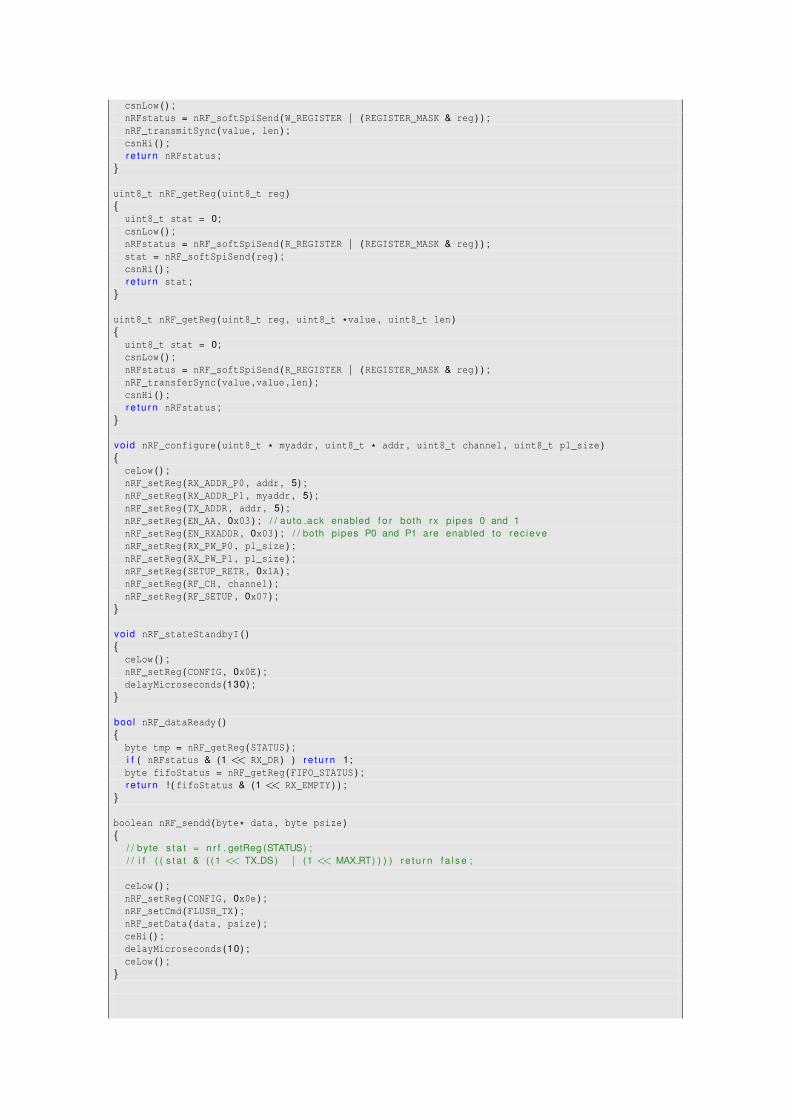
csnLow ( ) ;nRFstatus = nRF_softSpiSend (W_REGISTER | (REGISTER_MASK & reg ) ) ;nRF_transmitSync (value , len ) ;csnHi ( ) ;r e t u r n nRFstatus ;
}
uint8_t nRF_getReg (uint8_t reg ){
uint8_t stat = 0;csnLow ( ) ;nRFstatus = nRF_softSpiSend (R_REGISTER | (REGISTER_MASK & reg ) ) ;stat = nRF_softSpiSend (reg ) ;csnHi ( ) ;r e t u r n stat ;
}
uint8_t nRF_getReg (uint8_t reg , uint8_t *value , uint8_t len ){
uint8_t stat = 0;csnLow ( ) ;nRFstatus = nRF_softSpiSend (R_REGISTER | (REGISTER_MASK & reg ) ) ;nRF_transferSync (value , value , len ) ;csnHi ( ) ;r e t u r n nRFstatus ;
}
vo id nRF_configure (uint8_t * myaddr , uint8_t * addr , uint8_t channel , uint8_t pl_size ){
ceLow ( ) ;nRF_setReg (RX_ADDR_P0 , addr , 5) ;nRF_setReg (RX_ADDR_P1 , myaddr , 5) ;nRF_setReg (TX_ADDR , addr , 5) ;nRF_setReg (EN_AA , 0x03 ) ; / / auto ack enabled f o r both rx pipes 0 and 1nRF_setReg (EN_RXADDR , 0x03 ) ; / / both pipes P0 and P1 are enabled to rec ievenRF_setReg (RX_PW_P0 , pl_size ) ;nRF_setReg (RX_PW_P1 , pl_size ) ;nRF_setReg (SETUP_RETR , 0x1A ) ;nRF_setReg (RF_CH , channel ) ;nRF_setReg (RF_SETUP , 0x07 ) ;
}
vo id nRF_stateStandbyI ( ){
ceLow ( ) ;nRF_setReg (CONFIG , 0x0E ) ;delayMicroseconds (130) ;
}
bool nRF_dataReady ( ){
byte tmp = nRF_getReg (STATUS ) ;i f ( nRFstatus & (1 << RX_DR ) ) r e t u r n 1 ;byte fifoStatus = nRF_getReg (FIFO_STATUS ) ;r e t u r n ! ( fifoStatus & (1 << RX_EMPTY ) ) ;
}
boolean nRF_sendd (byte* data , byte psize ){
/ / byte s t a t = n r f . getReg (STATUS) ;/ / i f ( ( s t a t & ( ( 1 << TX DS) | (1 << MAX RT) ) ) ) r e t u r n f a l s e ;
ceLow ( ) ;nRF_setReg (CONFIG , 0x0e ) ;nRF_setCmd (FLUSH_TX ) ;nRF_setData (data , psize ) ;ceHi ( ) ;delayMicroseconds (10) ;ceLow ( ) ;
}
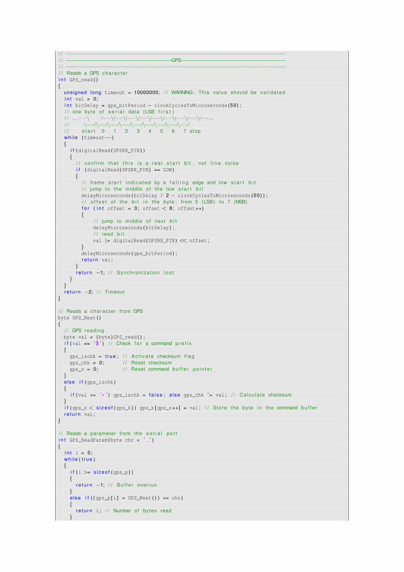
/ / −−−−−−−−−−−−−−−−−−−−−−−−−−−−−−−−−−−−−−−−−−−−−−−−−−−−−−−−−−−−−−−−−−−−−−−−−−−/ / −−−−−−−−−−−−−−−−−−−−−−−−−−−−−−−−−−−−GPS−−−−−−−−−−−−−−−−−−−−−−−−−−−−−−−−−−−−/ / −−−−−−−−−−−−−−−−−−−−−−−−−−−−−−−−−−−−−−−−−−−−−−−−−−−−−−−−−−−−−−−−−−−−−−−−−−−/ / Reads a GPS charac te ri n t GPS_read ( ){
unsigned long timeout = 10000000; / / WARNING: This value should be v a l i d a te di n t val = 0;i n t bitDelay = gps_bitPeriod − clockCyclesToMicroseconds (50) ;/ / one byte o f s e r i a l data (LSB f i r s t )/ / ...−−\ /−−\/−−\/−−\/−−\/−−\/−−\/−−\/−−\/−−.../ / \−−/\−−/\−−/\−−/\−−/\−−/\−−/\−−/\−−// / s t a r t 0 1 2 3 4 5 6 7 stopwhi le (timeout−−){
i f (digitalRead (GPSRX_PIN ) ){
/ / conf i rm t h a t t h i s i s a r e a l s t a r t b i t , not l i n e noisei f (digitalRead (GPSRX_PIN ) == LOW ){
/ / frame s t a r t i n d i c a t e d by a f a l l i n g edge and low s t a r t b i t/ / jump to the middle o f the low s t a r t b i tdelayMicroseconds (bitDelay / 2 − clockCyclesToMicroseconds (50) ) ;/ / o f f s e t o f the b i t i n the byte : from 0 (LSB) to 7 (MSB)f o r ( i n t offset = 0; offset < 8; offset++){
/ / jump to middle o f next b i tdelayMicroseconds (bitDelay ) ;/ / read b i tval |= digitalRead (GPSRX_PIN ) << offset ;
}delayMicroseconds (gps_bitPeriod ) ;r e t u r n val ;
}r e t u r n −1; / / Synchron iza t ion l o s t
}}r e t u r n −2; / / Timeout
}
/ / Reads a charac te r from GPSbyte GPS_Next ( ){
/ / GPS readingbyte val = (byte )GPS_read ( ) ;i f (val == '$ ' ) / / Check f o r a command p r e f i x{
gps_ischk = t rue ; / / Ac t i va te checksum f l a ggps_chk = 0; / / Reset checksumgps_n = 0; / / Reset command b u f f e r p o i n t e r
}else i f (gps_ischk ){
i f (val == ' * ' ) gps_ischk = f a l s e ; e lse gps_chk ˆ= val ; / / Ca lcu la te checksum}i f (gps_n < s i z e o f (gps_k ) ) gps_k [ gps_n++] = val ; / / Store the byte i n the command b u f f e rr e t u r n val ;
}
/ / Reads a parameter from the s e r i a l po r ti n t GPS_ReadParam (byte chr = ' , ' ){
i n t i = 0;wh i le ( t r ue ){
i f (i >= s i z e o f (gps_p ) ){
r e t u r n −1; / / Bu f fe r overrun}else i f ( ( gps_p [ i ] = GPS_Next ( ) ) == chr ){
r e t u r n i ; / / Number o f bytes read}
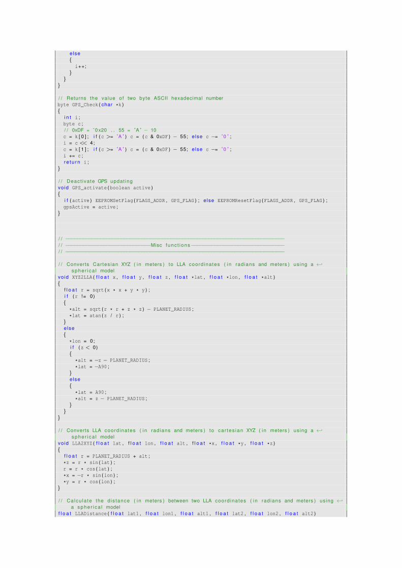
else{
i++;}
}}
/ / Returns the value o f two byte ASCII hexadecimal numberbyte GPS_Check ( char *k ){
i n t i ;byte c ;/ / 0xDF = ˜0 x20 . . 55 = 'A ' − 10c = k [ 0 ] ; i f (c >= 'A ' ) c = (c & 0xDF ) − 55; e lse c −= ' 0 ' ;i = c << 4;c = k [ 1 ] ; i f (c >= 'A ' ) c = (c & 0xDF ) − 55; e lse c −= ' 0 ' ;i += c ;r e t u r n i ;
}
/ / Deact iva te GPS updat ingvo id GPS_activate (boolean active ){
i f (active ) EEPROMSetFlag (FLAGS_ADDR , GPS_FLAG ) ; e lse EEPROMResetFlag (FLAGS_ADDR , GPS_FLAG ) ;gpsActive = active ;
}
/ / −−−−−−−−−−−−−−−−−−−−−−−−−−−−−−−−−−−−−−−−−−−−−−−−−−−−−−−−−−−−−−−−−−−−−−−−−−−/ / −−−−−−−−−−−−−−−−−−−−−−−−−−−−−Misc func t ions−−−−−−−−−−−−−−−−−−−−−−−−−−−−−−−−/ / −−−−−−−−−−−−−−−−−−−−−−−−−−−−−−−−−−−−−−−−−−−−−−−−−−−−−−−−−−−−−−−−−−−−−−−−−−−
/ / Converts Car tes ian XYZ ( i n meters ) to LLA coord ina tes ( i n rad ians and meters ) using a ←↩s p h e r i c a l model
vo id XYZ2LLA ( f l o a t x , f l o a t y , f l o a t z , f l o a t *lat , f l o a t *lon , f l o a t *alt ){
f l o a t r = sqrt (x * x + y * y ) ;i f (r != 0){
*alt = sqrt (r * r + z * z ) − PLANET_RADIUS ;
*lat = atan (z / r ) ;}else{
*lon = 0;i f (z < 0){
*alt = −z − PLANET_RADIUS ;
*lat = −A90 ;}else{
*lat = A90 ;
*alt = z − PLANET_RADIUS ;}
}}
/ / Converts LLA coord ina tes ( i n rad ians and meters ) to ca r tes ian XYZ ( i n meters ) using a ←↩s p h e r i c a l model
vo id LLA2XYZ ( f l o a t lat , f l o a t lon , f l o a t alt , f l o a t *x , f l o a t *y , f l o a t *z ){
f l o a t r = PLANET_RADIUS + alt ;
*z = r * sin (lat ) ;r = r * cos (lat ) ;
*x = −r * sin (lon ) ;
*y = r * cos (lon ) ;}
/ / Ca lcu la te the d is tance ( i n meters ) between two LLA coord ina tes ( i n rad ians and meters ) using ←↩a s p h e r i c a l model
f l o a t LLADistance ( f l o a t lat1 , f l o a t lon1 , f l o a t alt1 , f l o a t lat2 , f l o a t lon2 , f l o a t alt2 )
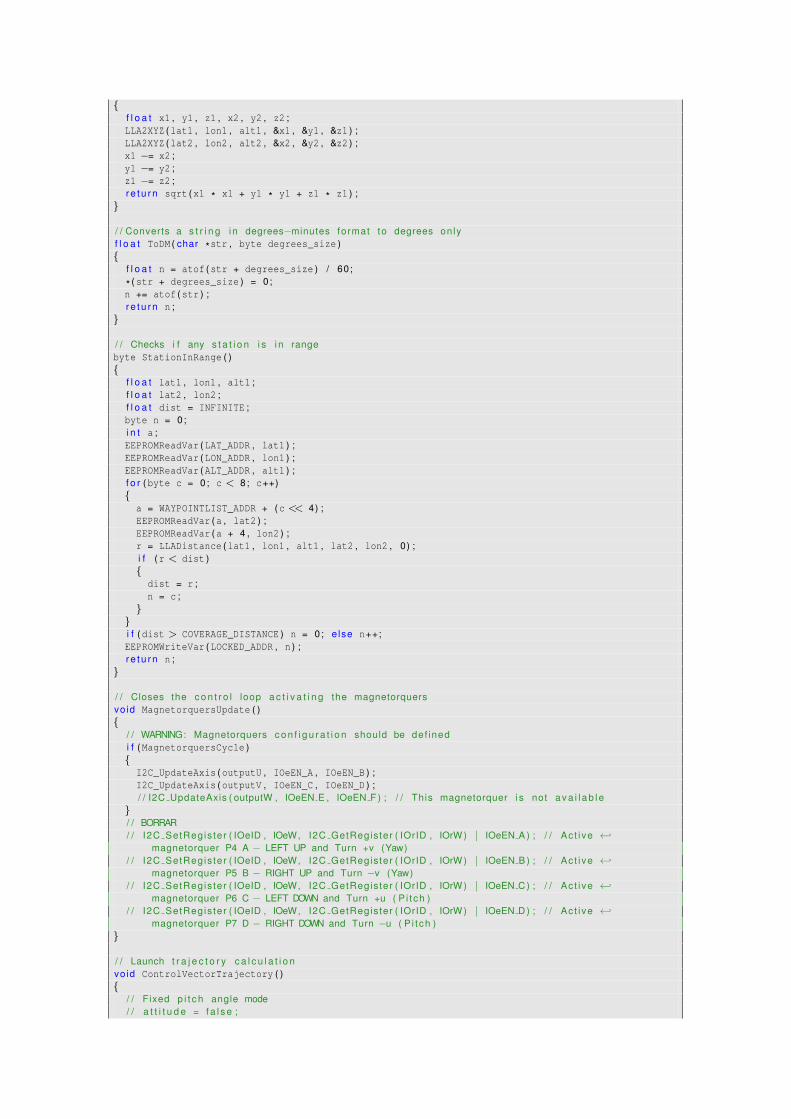
{f l o a t x1 , y1 , z1 , x2 , y2 , z2 ;LLA2XYZ (lat1 , lon1 , alt1 , &x1 , &y1 , &z1 ) ;LLA2XYZ (lat2 , lon2 , alt2 , &x2 , &y2 , &z2 ) ;x1 −= x2 ;y1 −= y2 ;z1 −= z2 ;r e t u r n sqrt (x1 * x1 + y1 * y1 + z1 * z1 ) ;
}
/ / Converts a s t r i n g i n degrees−minutes format to degrees onlyf l o a t ToDM ( char *str , byte degrees_size ){
f l o a t n = atof (str + degrees_size ) / 60;
* (str + degrees_size ) = 0 ;n += atof (str ) ;r e t u r n n ;
}
/ / Checks i f any s t a t i o n i s i n rangebyte StationInRange ( ){
f l o a t lat1 , lon1 , alt1 ;f l o a t lat2 , lon2 ;f l o a t dist = INFINITE ;byte n = 0;i n t a ;EEPROMReadVar (LAT_ADDR , lat1 ) ;EEPROMReadVar (LON_ADDR , lon1 ) ;EEPROMReadVar (ALT_ADDR , alt1 ) ;f o r (byte c = 0; c < 8; c++){
a = WAYPOINTLIST_ADDR + (c << 4) ;EEPROMReadVar (a , lat2 ) ;EEPROMReadVar (a + 4 , lon2 ) ;r = LLADistance (lat1 , lon1 , alt1 , lat2 , lon2 , 0) ;i f (r < dist ){
dist = r ;n = c ;
}}i f (dist > COVERAGE_DISTANCE ) n = 0; e lse n++;EEPROMWriteVar (LOCKED_ADDR , n ) ;r e t u r n n ;
}
/ / Closes the c o n t r o l loop a c t i v a t i n g the magnetorquersvo id MagnetorquersUpdate ( ){
/ / WARNING: Magnetorquers c o n f i g u r a t i o n should be def inedi f (MagnetorquersCycle ){
I2C_UpdateAxis (outputU , IOeEN_A , IOeEN_B ) ;I2C_UpdateAxis (outputV , IOeEN_C , IOeEN_D ) ;/ / I2C UpdateAxis ( outputW , IOeEN E , IOeEN F ) ; / / This magnetorquer i s not a v a i l a b l e
}/ / BORRAR/ / I2C SetRegis ter ( IOeID , IOeW, I2C GetRegis ter ( IOrID , IOrW ) | IOeEN A ) ; / / Ac t i ve ←↩
magnetorquer P4 A − LEFT UP and Turn +v (Yaw)/ / I2C SetRegis ter ( IOeID , IOeW, I2C GetRegis ter ( IOrID , IOrW ) | IOeEN B ) ; / / Ac t i ve ←↩
magnetorquer P5 B − RIGHT UP and Turn −v (Yaw)/ / I2C SetRegis ter ( IOeID , IOeW, I2C GetRegis ter ( IOrID , IOrW ) | IOeEN C ) ; / / Ac t i ve ←↩
magnetorquer P6 C − LEFT DOWN and Turn +u ( P i t ch )/ / I2C SetRegis ter ( IOeID , IOeW, I2C GetRegis ter ( IOrID , IOrW ) | IOeEN D ) ; / / Ac t i ve ←↩
magnetorquer P7 D − RIGHT DOWN and Turn −u ( P i t ch )}
/ / Launch t r a j e c t o r y c a l c u l a t i o nvo id ControlVectorTrajectory ( ){
/ / Fixed p i t c h angle mode/ / a t t i t u d e = f a l s e ;
/ / ta rgetU = TARGET ANGLE;
/ / P i t ch t a r g e t angle c a l c u l a t i o n as a f u n c t i o n o f the cu r ren t a l t i t u d e and three def ined ←↩po in t s
i f (altitude >= ALT3 )targetU = ANGLE3 ;
e lse i f (altitude >= ALT2 )targetU = ANGLE2 + (ANGLE3 − ANGLE2 ) * (altitude − ALT2 ) / (ALT3 − ALT2 ) ;
e lse i f (altitude >= ALT1 )targetU = ANGLE1 + (ANGLE2 − ANGLE1 ) * (altitude − ALT1 ) / (ALT2 − ALT1 ) ;
e lsetargetU = ANGLE1 ;
}/ / Closes the c o n t r o l vec to r loop a c t i v a t i n g the c o n t r o l vec to r nozzlesvo id ControlVectorUpdate ( ){
/ / WARNING: Cont ro l Vector c o n f i g u r a t i o n should be def inedboolean a , b , c , d ;i f (MagnetorquersCycle ){
/ / PENDING: I t should be a SPI command, not a I2C commandi f (outputW > 0 .1 ){
SPI_Config (IOeEN_B , IOeEN_C , IOeEN_A , IOeEN_D ) ;}else i f (outputW < 0 .1 ){
SPI_Config (IOeEN_A , IOeEN_D , IOeEN_B , IOeEN_C ) ;}else{
a = f a l s e ;b = f a l s e ;c = f a l s e ;d = f a l s e ;i f (outputU > 0 .1 ){
b = t rue ;d = t rue ;
}else i f (outputU < 0 .1 ){
a = t rue ;c = t rue ;
}i f (outputV > 0 .1 ){
a = t rue ;b = t rue ;
}else i f (outputV < 0 .1 ){
c = t rue ;d = t rue ;
}i f (a )SPI_TurnOn (IOeEN_A ) ; e lse SPI_TurnOff (IOeEN_A ) ;i f (b )SPI_TurnOn (IOeEN_B ) ; e lse SPI_TurnOff (IOeEN_B ) ;i f (c )SPI_TurnOn (IOeEN_C ) ; e lse SPI_TurnOff (IOeEN_C ) ;i f (d )SPI_TurnOn (IOeEN_D ) ; e lse SPI_TurnOff (IOeEN_D ) ;
}}
}
/ / Ca lcu la tes the PID a lgo r i t hm f o r the given valuesf l o a t CalculatePID ( f l o a t value , f l o a t target , f l o a t *acc , f l o a t *last ){
f l o a t h = target − value ; / / P ro po r t i o na l
*acc += h * dt ; / / I n t e g r a lf l o a t g = (h − *last ) / dt ; / / D e r i v a t i v eg = h * controlP + *acc * controlI + g * controlD ;
*last = h ;r e t u r n g ;
}
/ / Ac t i va te a t t i t u d e c o n t r o l and con f igu re PID c o n t r o l l e r parametersvo id AttitudeOn ( f l o a t p , f l o a t i , f l o a t d ){
controlP = p ;controlI = i ;controlD = d ;EEPROMWriteVar (CONTROL_P_ADDR , p ) ;EEPROMWriteVar (CONTROL_I_ADDR , i ) ;EEPROMWriteVar (CONTROL_D_ADDR , d ) ;EEPROMSetFlag (FLAGS_ADDR , ATTITUDE_FLAG ) ;attitude = t rue ;
}
/ / Deact iva te a t t i t u d e c o n t r o lvo id AttitudeOff ( ){
EEPROMResetFlag (FLAGS_ADDR , ATTITUDE_FLAG ) ;attitude = f a l s e ;
}
/ / Set the mission s ta tus and tu rn o f payload i f i t i s standbyvoid SetMission (byte n ){
mission = n ;EEPROMWrite (MISSION_ADDR , 1 , &mission ) ;i f (mission == MISSION_STANDBY ) Payload_activate ( f a l s e ) ;
}
/ / Ac t i va tes i f se lec ted the payload power supplyvo id Payload_activate (boolean active ){
i f (active ){
/ / Turn on payload power supplyI2C_TurnOn (IOeEN_2_6V ) ;I2C_TurnOn (IOeEN_1_5V ) ;I2C_TurnOn (IOeEN_3_3V_1 ) ;/ / Turn on the rad ioceLow ( ) ;csnHi ( ) ;nRF_configure (URX_ADDR , UTX_ADDR , RF_CHANNEL , PL_SIZE ) ;nRF_stateStandbyI ( ) ;/ / S t a r t to record because at t h i s po in t , t a r g e t i s lockedI2C_SetRegister (CamID , CamReg02 , B10000000 ) ; / / 15 fps , 50Hz , normal DCLKP and ACFDET Auto ←↩
mode}else{
I2C_TurnOff (IOeEN_3_3V_1 ) ;I2C_TurnOff (IOeEN_2_6V ) ;I2C_TurnOff (IOeEN_1_5V ) ;
}payloadActive = active ;
}
/ / −−−−−−−−−−−−−−−−−−−−−−−−−−−−−−−−−−−−−−−−−−−−−−−−−−−−−−−−−−−−−−−−−−−−−−−−−−−/ / −−−−−−−−−−−−−−−−−−−−−−−−−−−−−Reset procedure−−−−−−−−−−−−−−−−−−−−−−−−−−−−−−−/ / −−−−−−−−−−−−−−−−−−−−−−−−−−−−−−−−−−−−−−−−−−−−−−−−−−−−−−−−−−−−−−−−−−−−−−−−−−−
# i f !RESET EEPROM/ / −−−−−−−−−−−−−−−−−−−−−−−−−−−−−−−−−−−−−−−−−−−−−−−−−−−−−−−−−−−−−−−−−−−−−−−−−−−/ / −−−−−−−−−−−−−−−−−−−−−−−−−−−−−Main func t ions−−−−−−−−−−−−−−−−−−−−−−−−−−−−−−−−/ / −−−−−−−−−−−−−−−−−−−−−−−−−−−−−−−−−−−−−−−−−−−−−−−−−−−−−−−−−−−−−−−−−−−−−−−−−−−vo id setup ( ){
/ / S t a r t i n g I2C busi2c_rxBufferIndex = 0;i2c_rxBufferLength = 0;i2c_txBufferIndex = 0;i2c_txBufferLength = 0;/ / i n i t i a l i z e two wire i n t e r f a c e s ta tei2c_state = TWI_READY ;
/ / a c t i v a t e i n t e r n a l p u l l−ups f o r t w i/ / as per note from atmega8 manual pg167I2C_sbi (PORTC , 4) ;I2C_sbi (PORTC , 5) ;
/ / i n i t i a l i z e t w i p resca le r and b i t r a teI2C_cbi (TWSR , TWPS0 ) ;I2C_cbi (TWSR , TWPS1 ) ;TWBR = ( ( I2C_CPU_FREQ / I2C_TWI_FREQ ) − 16) / 2 ;
/ * t w i b i t r a te formula from atmega128 manual pg 204SCL Frequency = CPU Clock Frequency / (16 + (2 * TWBR) )note : TWBR should be 10 or h igher f o r master modeI t i s 72 f o r a 16mhz Wir ing board wi th 100kHz TWI * /
/ / enable t w i module , acks , and t w i i n t e r r u p tTWCR = _BV (TWEN ) | _BV (TWIE ) | _BV (TWEA ) ;
/ / I n i t i a l i z i n g I2C sensorsI2C_SetRegister (AccID , 0x20 , B00111111 ) ; / / I n i t i a l i z e a t 1000 Hz sampling rate , low pass cut−←↩
o f f a t 780 Hz . Reg is te r 32 (0 x20 ) − CTRL REG1: PM2 PM1 PM0 DR1 DR2 Zen Yen XenI2C_SetRegister (AccID , 0x23 , B00000000 ) ; / / From −6g to +6g . g=5461.3 f ; Reg is te r (0 x23 ) − ←↩
CTRL REG4: BDU BLE FS1 FS0 STsign 0 ST SIMI2C_SetRegister (GyroID , 0x3E , B00000001 ) ; / / I n t e r n a l o s c i l l a t o r . Reg is te r 62 (0x3E ) a Power←↩
Management : H RESET SLEEP STBY XG STBY YG STBY ZG CLK SEL Bit2 CLK SEL Bit2 CLK SEL Bit1 ←↩CLK SEL Bit0
I2C_SetRegister (GyroID , 0x16 , B00011011 ) ; / / I n i t i a l i z e a t 1000 Hz sampling rate , DLPF at 188 ←↩Hz . Reg is te r 22 (0 x16 ) a D i g i t a l Low Pass F i l t e r , F u l l Scale : FS SEL Bit4 FS SEL Bit3 ←↩DLPF CFG Bit2 DLPF CFG Bit1 DLPF CFG Bit0
I2C_SetRegister (IOeID , IOeW , IOeWstatus ) ;
/ / S t a r t i n g SPI busSPI . begin ( ) ; / / SPI bus f o r launcher communications
/ / S t a r t i n g GPSgps_baudRate = 4800;gps_bitPeriod = 1000000 / gps_baudRate ;digitalWrite (GPSTX_PIN , HIGH ) ;delayMicroseconds (gps_bitPeriod ) ; / / i f we were low t h i s es tab l i shes the end
/ / Conf igur ing the rad iopinMode (SOFT_MOSI , OUTPUT ) ;pinMode (SOFT_MISO , INPUT ) ;pinMode (SOFT_SCK , OUTPUT ) ;digitalWrite (SOFT_MOSI , LOW ) ;digitalWrite (SOFT_SCK , LOW ) ;pinMode (pCE , OUTPUT ) ;pinMode (pCSN , OUTPUT ) ;
/ / Con f igur ing EEPROM and mission s ta te recoveryEEPROMReadVar (MISSION_ADDR , mission ) ;time = micros ( ) ; / / Time stampg = 1.796265E−03; / / g = 6.0 * 9.81 / 32768;gz = 1.704193E−03; / / g = 6.0 * 9.81 * (9 .81 / 10.34) / 32768;h = .06103515625; / / h = 2000 / 32768;maxg = EEPROMGetFlag (FLAGS_ADDR , MAXG_FLAG ) ;attitude = EEPROMGetFlag (FLAGS_ADDR , ATTITUDE_FLAG ) ;GPS_activate (EEPROMGetFlag (FLAGS_ADDR , GPS_FLAG ) ) ;Payload_activate (EEPROMGetFlag (FLAGS_ADDR , PAYLOAD_FLAG ) ) ;EEPROMReadVar (CONTROL_P_ADDR , controlP ) ;EEPROMReadVar (CONTROL_I_ADDR , controlI ) ;EEPROMReadVar (CONTROL_D_ADDR , controlD ) ;/ / EEPROMReadVar(TARGET U ADDR, targetU ) ;/ / EEPROMReadVar(TARGET V ADDR, ta rge tV ) ;/ / EEPROMReadVar(TARGET W ADDR, targetW ) ;targetU = 0;targetV = 0;targetW = 0;accU = 0;accV = 0;accW = 0;lastU = 0;
lastV = 0;lastW = 0;timeMagnetorquers = 0;
}
vo id loop ( ){
byte c ;f l o a t newlat ;f l o a t newlon ;f l o a t newalt ;byte newsta ;
i f (mission < MISSION_DEPLOY ){
/ / Acce le ra t i on f i l t e r i n gi = 0;j = 0;k = 0;r = (1 << INTEGRATOR_CYCLES ) ;wh i le (r−−){
i += I2C_GetValue (AccID , AccX ) ;j += I2C_GetValue (AccID , AccY ) ;k += I2C_GetValue (AccID , AccZ ) ;/ / delay ( 1 ) ;
}
/ / Accelerometer s a t u r a t i o n de tec t i oni f (k > (32000 << INTEGRATOR_CYCLES ) ){
i f (maxg ){
EEPROMSetFlag (FLAGS_ADDR , MAXG_FLAG ) ;}maxg = t rue ;
}else{
maxg = f a l s e ;}data . i = ( f l o a t ) (i >> INTEGRATOR_CYCLES ) * g ;data . j = ( f l o a t ) (j >> INTEGRATOR_CYCLES ) * g ;data . k = ( f l o a t ) (k >> INTEGRATOR_CYCLES ) * gz ;/ / I n t e g r a t o r s . v=a* dt ; e=v * dtdata . l += data . i * dt ; / / Speeddata . m += data . j * dt ;data . n += data . k * dt ;data . x += data . l * dt ; / / Pos i t i ondata . y += data . m * dt ;data . z += data . n * dt ;
}else{
/ / Sun t r a c k e r c a l c u l a t i o nsun . x = (analogRead (SUNA_PIN ) − analogRead (SUND_PIN ) ) / 1024; / / CAUTION: Sun t r a c k e r should←↩
be def inedsun . y = (analogRead (SUNA_PIN ) − analogRead (SUND_PIN ) ) / 1024;sun . z = (analogRead (SUNE_PIN ) − analogRead (SUNF_PIN ) ) / 1024;
}
/ / Gyros b ias c o r r e c t i o ndata . u = (I2C_GetValue (GyroID , GyroX ) − bias . u ) * h ;data . v = (I2C_GetValue (GyroID , GyroY ) − bias . v ) * h ;data . w = (I2C_GetValue (GyroID , GyroZ ) − bias . w ) * h ;data . t = ( ( ( f l o a t ) (I2C_GetValue (GyroID , GyroT ) + 13200) ) / 280.0f ) * 100 + 3500; / / Ce ls ius = ( (←↩
T+13200) /280) +35data . d = micros ( ) − time ; i f (data . d < 0) data . d = −data . d ;time += data . d ;dt = ( f l o a t )data . d / 1000000.0; / / Seconds
/ / I n t e g r a t o r c=w* dtdata . a += data . u * dt ; / / A t t i t u d e WARNING: TO BE REPLACED BY LSM303DLHC COMPASS
data . b += data . v * dt ;data . c += data . w * dt ;/ *data . a = I2C GetValue (CompID , CompX) ; / / Magnetic a t t i t u d edata . b = I2C GetValue (CompID , CompY) ;data . c = I2C GetValue (CompID , CompZ) ;
* /
altitude = 0; / / A l t i t u d e c a l c u l a t i o nspeedv = 0; / / V e r t i c a l speed c a l c u l a t i o n
/ / Magnetorquers Cycle de tec t i ontimeMagnetorquers += data . d ;i f (timeMagnetorquers > 20000){
MagnetorquersCycle = t rue ;timeMagnetorquers −= 20000;
}
/ / GPS cyc le every secondtimeGPS += data . d ;i f (timeGPS > 1000000){
timeGPS −= 1000000;gps_valid = f a l s e ;i f (gpsActive ){
i f (GPS_Next ( ) == '$ ' ) i f (GPS_Next ( ) == 'G ' ) i f (GPS_Next ( ) == 'P ' ) i f (GPS_Next ( ) == 'G ' ) i f←↩(GPS_Next ( ) == 'G ' ) i f (GPS_Next ( ) == 'A ' ) i f (GPS_Next ( ) == ' , ' ) / / Check f o r $GPGGA ←↩command
{i f (GPS_ReadParam ( ) >= 0) / / Time i n UTC of p o s i t i o ni f (GPS_ReadParam ( ) > 2) / / La t i t ude of p o s i t i o n{
newlat = ToDM ( ( char * )&gps_p [ 0 ] , 2) ; / / Parse the l a t i t u d e and s to re i t i n a temporary ←↩v a r i a b l e before v a l i d a t i o n
i f (GPS_ReadParam ( ) > 3) / / La t i t ude N or S{
newlon = ToDM ( ( char * )&gps_p [ 0 ] , 3) ; / / Parse the long i t ude and s to re i t i n a ←↩temporary v a r i a b l e before v a l i d a t i o n
i f (GPS_ReadParam ( ) >= 0) / / Longi tude of p o s i t i o ni f (GPS_ReadParam ( ) >= 0) / / Longi tude E or Wi f (GPS_ReadParam ( ) >= 0) / / GPS q u a l i t y (0= f i x not ←↩
ava i l ab le , 1=Non−d i f f e r e n t i a l GPS f i x ava i l ab le , 2= D i f f e r e n t i a l GPS (WAAS) f i x ←↩ava i l ab le , 6=Est imated )
{newsta = gps_p [ 0 ] ; / / Parse GPS al ignmenti f (GPS_ReadParam ( ) >= 0) / / Number o f s a t e l l i t e s (00 to 12)i f (GPS_ReadParam ( ) >= 0) / / Ho r i zon ta l d i l u t i o n o f p r e c i s i o n (0 .5 to ←↩
99.9)i f (GPS_ReadParam ( ) > 0) / / Antenna a l t i t u d e above mean sea l e v e l (−9999.9 ←↩
to 99999.9){
newalt = atof ( ( char * )&gps_p [ 0 ] ) ; / / Parse the a l t i t u d e and s to re i t i n a ←↩temporary v a r i a b l e before v a l i d a t i o n
i f (GPS_ReadParam ( ) >= 0) / / Un i ts o f antenna a l t i t u d e , meters Mi f (GPS_ReadParam ( ) >= 0) / / Height o f geoid above e l l i p s o i d (−999.9 to←↩
9999.9)i f (GPS_ReadParam ( ) >= 0) / / Un i ts o f geoid height , meters Mi f (GPS_ReadParam ( ) >= 0) / / Age of d i f f e r e n t i a l GPS data , seconds Nu l li f (GPS_ReadParam ( ' * ' ) >= 0) / / D i f f e r e n t i a l re ference s t a t i o n ID Nu l li f (GPS_ReadParam (10) >= 2) / / Checksum *HH ( two ←↩
hex d i g i t s represen t ing an 8 b i t exc lus i ve OR of a l l charac te rs between , but←↩not i nc lud ing , the '$ ' and ' * ' )
{i f (gps_chk == GPS_Check ( ( char * )&gps_p [ 0 ] ) ) / / Checksum v a l i d a t i o n{
gps_lat = newlat ;gps_lon = newlon ;gps_alt = newalt ;gps_valid = (newsta != ' 0 ' ) ;/ *i f ( gps va l i d )
{LLA2XYZ( gps la t , gps lon , gps a l t , &data . x , &data . y , &data . z ) ; / / IMU ←↩
c a l i b r a t e d}* // / Computation o f the magnetic vec to r d e c l i n a t i o n#define wmm (pos ) ( ( char )EEPROM_read (DECLINATION_ADDR + pos ) )i n t wmm_lat = ( i n t )gps_lat ;i n t wmm_lon = ( i n t )gps_lon ;f l o a t wmm_yb = gps_lat − wmm_lat ;f l o a t wmm_ya = 1.0 − wmm_ya ;f l o a t wmm_xb = gps_lon − wmm_lon ;f l o a t wmm_xa = 1.0 − wmm_xa ;i n t wmm_pos = (wmm_lat / 10 + 7) * 25 + (wmm_lon / 15 + 12) ;mag_dec = ( ( f l o a t )wmm (wmm_pos ) ) * wmm_xa * wmm_ya +
( ( f l o a t )wmm (wmm_pos + 1) ) * wmm_xb * wmm_ya +( ( f l o a t )wmm (wmm_pos + 25) ) * wmm_xa * wmm_yb +( ( f l o a t )wmm (wmm_pos + 26) ) * wmm_xb * wmm_yb ;
}}
}}
}}
}}
}
/ / A t t i t u d e c o n t r o li f (attitude ){
/ / PID c o n t r o l l e routputU = CalculatePID (data . a , targetU , &accU , &lastU ) ; / / PID c o n t r o l l e r f o r p i t c h c o n t r o loutputV = CalculatePID (data . b , targetV , &accV , &lastV ) ; / / PID c o n t r o l l e r f o r yaw c o n t r o loutputW = CalculatePID (data . c , targetW , &accW , &lastW ) ; / / PID c o n t r o l l e r f o r r o l l c o n t r o l
}
swi tch (mission ){
case MISSION_INOP : / / Any main system f a i l or GPS not a l igned . The s a t e l l i t e i s not ready←↩to be launched
/ / Reset the c o n f i g u r a t i o n to d e f a u l t si f ( ! gpsActive ) GPS_activate ( t r ue ) ;i f (gpsActive ){
SetMission (MISSION_RAMP ) ;}break ;
case MISSION_RAMP : / / IMU i n t e g r a t o r s are a c t i v e and wa i t i ng f o r ba l loon re lease . Next ←↩mission s ta te when f i r s t stage burn−i n i s detected . The ba l loon from an ex te rna l GPS or ←↩a person ac t i ves the f i r s t stage i g n i t i o n . The s a t e l l i t e can not a c t i v e the f i r s t stage ←↩by i t s e l f
i f (maxg ){
/ / Guardar l a a c t i t u d de l l os gyros/ / Guardar en l a EEPROM las coordenadas GPSEEPROMWriteVar (LAT_ADDR , gps_lat ) ; / / F i r s t known stage coord ina tesEEPROMWriteVar (LON_ADDR , gps_lon ) ;EEPROMWriteVar (ALT_ADDR , gps_alt ) ;/ / Guardar e l vec to r magnetico t e r r e s t r eGPS_activate ( f a l s e ) ;AttitudeOn (2 , 5 , 1) ;SetMission (MISSION_STAGE1 ) ;
}break ;
case MISSION_STAGE1 : / / IMU i n t e g r a t o r s are a c t i v e and vec to r c o n t r o l i s a c t i v e . Next ←↩mission s ta te when f i r s t stage burnout i s detected
ControlVectorTrajectory ( ) ;ControlVectorUpdate ( ) ;i f ( ! maxg ){
I2C_TurnOn (IOeEN_GPS ) ;GPS_activate ( t r ue ) ;
SetMission (MISSION_BURNOUT1 ) ;}break ;
case MISSION_BURNOUT1 : / / IMU i n t e g r a t o r s are a c t i v e and vec to r c o n t r o l i s i n i d l e i n order ←↩to keep the a t t i t u d e . Next mission stage one minute before apogee and detected by low ←↩v e r t i c a l speed
ControlVectorTrajectory ( ) ;ControlVectorUpdate ( ) ;i f (speedv < 80){
targetU = 0;AttitudeOn (2 , 5 , 1) ;SetMission (MISSION_SPIN ) ;
}break ;
/ / case MISSION TURN : / / INOP . IMU i n t e g r a t o r s are a c t i v e and a vec to r c o n t r o l maneuver i s←↩done to match the apogee plane . Next mission stage when maneuver i s completed
/ / / / NOT IMPLEMENTED/ / ControlVectorUpdate ( ) ;/ / i f ( speedv < 100)/ / {/ / SetMission ( MISSION TILT ) ;/ / }/ / break ;/ / case MISSION TILT : / / INOP . IMU i n t e g r a t o r s are a c t i v e and a vec to r c o n t r o l maneuver i s←↩
done to match the heading plane p a r a l l e l to the ground . Next mission stage when maneuver i s←↩completed
/ / / / NOT IMPLEMENTED/ / ControlVectorUpdate ( ) ;/ / i f ( t r ue )/ / {/ / SetMission ( MISSION SPIN ) ;/ / }/ / break ;
case MISSION_SPIN : / / IMU i n t e g r a t o r s are a c t i v e and a spin i s given to the launcher . At ←↩t h i s po in t an o r b i t a l speed p r e d i c t i o n i s ca l cu la ted based on the cu r ren t a l t i t u d e . I f ←↩GPS i s a v a i l a b l e a t o r b i t , i t w i l l be replaced f o r the r e a l one . Next mission stage when←↩
sp in i s achieved and apogee i s reached or passed then second stage i g n i t i o n i s ←↩a c t i v a t ed before
targetW = INFINITE ; / / Force a t t i t u d e c o n t r o l to sp inControlVectorUpdate ( ) ;i f ( ( data . w > 1000) && (digitalRead (IGNITION_PIN ) == LOW ) ){
digitalWrite (IGNITION_PIN , HIGH ) ;timeStamp = 0;
}i f (maxg ){
targetW = 0; / / Stop sp inSetMission (MISSION_STAGE2 ) ;
}else{
timeStamp += data . d ;i f (timeStamp > 10000000) / / 10 seconds w i thou t i g n i t i o n goes to STANDBY{
targetW = 0; / / Stop sp inSetMission (MISSION_STANDBY ) ; / / CAUTION: I n j e c t i o n sequence f a i l e d . Mission t ime ←↩
reduced}
}break ;
case MISSION_STAGE2 : / / IMU i n t e g r a t o r s are a c t i v e whi le the o r b i t a l speed i s achieved . Next←↩mission s ta te when second stage burnout i s detected . I f i g n i t i o n f a i l s , next mission ←↩
stage w i l l be STANDBYi f ( ! maxg ) SetMission (MISSION_DEPLOY ) ; / / O r b i t a l speed i s not detected , on ly the burn out ←↩
of the l a s t stagebreak ;
case MISSION_DEPLOY : / / IMU i n t e g r a t o r s are a c t i v e whi le s a t e l l i t e s are deployed . Next ←↩mission s ta te when a t t i t u d e c o n t r o l i s achieved . I f a t t i t u d e c o n t r o l f a i l s , next mission←↩
stage w i l l be STANDBYi f (MagnetorquersCycle ){
/ / EEPROMWriteVar (TARGET U ADDR, 0) ;/ / EEPROMWriteVar (TARGET V ADDR, 0) ;/ / EEPROMWriteVar (TARGET W ADDR, 0) ;targetU = 0;targetV = 0;targetW = 0;SetMission (MISSION_DAMPING ) ;
}break ;
case MISSION_DAMPING : / / IMU i n t e g r a t o r s are a c t i v e whi le a damping maneuver i s done by ←↩Magnetorquers . Next mission s ta te when s a t e l l i t e a t t i t u d e i s s t a b i l i z e d
MagnetorquersUpdate ( ) ;i f ( ( abs (targetU−data . a ) < 0 .1 ) && (abs (targetV−data . b ) < 0 .1 ) && (abs (targetW−data . c ) < ←↩
0 .1 ) ){
SetMission (MISSION_STANDBY ) ;}break ;
case MISSION_STANDBY : / / IMU i n t e g r a t o r s are a c t i v e but a l l the f u nc t i o ns are h ibernated . ←↩Every 10 seconds i t looks f o r any near ground s t a t i o n below 1200 km. Next mission s ta te ←↩when any ground s t a t i o n i s near
i f (MagnetorquersCycle ){
I2C_TurnOff (IOeEN_A ) ;I2C_TurnOff (IOeEN_B ) ;I2C_TurnOff (IOeEN_C ) ;I2C_TurnOff (IOeEN_D ) ;
}i f (StationInRange ( ) ) SetMission (MISSION_FOLLOWING ) ;/ / HIBERNATE FOR A WHILE ;break ;
case MISSION_FOLLOWING : / / IMU i n t e g r a t o r s are a c t i v e whi le the a t t i t u d e maneuver i s done to←↩po in t towards the ground s t a t i o n . Other near s t a t i o n s are checked i n between . Next ←↩
mission s ta te when the t a r g e t i s locked . I f ground s t a t i o n i s out o f range , next mission←↩stage w i l l be STANDBY
MagnetorquersUpdate ( ) ;i f ( ( abs (data . u ) < 0 .1 ) && (abs (data . v ) < 0 .1 ) && (abs (data . w ) < 0 .1 ) ) / / Target locked{
Payload_activate ( t r ue ) ;SetMission (MISSION_PAIRING ) ;
}break ;
case MISSION_PAIRING : / / Same as FOLLOWING but rad io−l i n k i s tes ted . Next mission s ta te when←↩l i n k i s es tab l i shed and new commands are uploaded . I f rad io−l i n k s f a i l s keeps the ←↩
cu r ren t mode . I f a new nearest ground s t a t i o n i s ava i l ab le , next mission stage w i l l be ←↩FOLLOWING. I f ground s t a t i o n i s out o f range , next mission stage w i l l be STANDBY
MagnetorquersUpdate ( ) ;/ / Sending request to the locked ground s t a t i o n every second when GPS i s a c t i v ei f (gpsActive ) nRF_sendd ( ( byte * )&data . i , PL_SIZE ) ; wh i le ( ! ( ( nRF_getReg (STATUS ) & ( ( 1 << ←↩
TX_DS ) | (1 << MAX_RT ) ) ) ) ) ; nRF_setReg (STATUS , (1 << TX_DS ) | (1 << MAX_RT ) ) ;i f (nRF_dataReady ( ) ){
nRF_getData ( ( byte * ) &data . x , PL_SIZE ) ; / / New commands a v a i l a b l eSetMission (MISSION_DOWNLOAD ) ;
}else i f ( f a l s e ) / / Locked ground s t a t i o n out o f range{
SetMission (MISSION_STANDBY ) ;}break ;
case MISSION_DOWNLOAD : / / Same as FOLLOWING but download i s done . I f rad io−l i n k s f a i l s o f a ←↩new nearest ground s t a t i o n i s ava i l ab le , next mission stage w i l l be FOLLOWING. I f ground←↩
s t a t i o n i s out o f range , next mission stage w i l l be STANDBYMagnetorquersUpdate ( ) ;/ / nRF sendd ( ( byte * )&data . i , PL SIZE ) ; wh i le ( ! ( ( nRF getReg (STATUS) & ( ( 1 << TX DS) | (1 <<←↩
MAX RT) ) ) ) ) ; nRF setReg (STATUS, (1 << TX DS) | (1 << MAX RT) ) ;i f ( f a l s e ) / / Locked ground s t a t i o n out o f range{
SetMission (MISSION_STANDBY ) ;}break ;
d e f a u l t : / / Mission phase number out o f range . Changes to STANDBYSetMission (MISSION_STANDBY ) ;
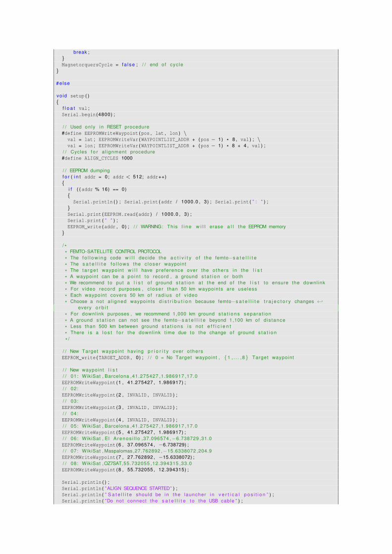
break ;}MagnetorquersCycle = f a l s e ; / / end of cyc le
}
#else
vo id setup ( ){
f l o a t val ;Serial . begin (4800) ;
/ / Used only i n RESET procedure#define EEPROMWriteWaypoint (pos , lat , lon ) \
val = lat ; EEPROMWriteVar (WAYPOINTLIST_ADDR + (pos − 1) * 8 , val ) ; \val = lon ; EEPROMWriteVar (WAYPOINTLIST_ADDR + (pos − 1) * 8 + 4 , val ) ;
/ / Cycles f o r a l ignment procedure#define ALIGN_CYCLES 1000
/ / EEPROM dumpingf o r ( i n t addr = 0; addr < 512; addr++){
i f ( ( addr % 16) == 0){
Serial . println ( ) ; Serial . print (addr / 1000.0 , 3) ; Serial . print ( ” : ” ) ;}Serial . print (EEPROM . read (addr ) / 1000.0 , 3) ;Serial . print ( ” ” ) ;EEPROM_write (addr , 0) ; / / WARNING: This l i n e w i l l erase a l l the EEPROM memory
}
/ ** FEMTO−SATELLITE CONTROL PROTOCOL
* The f o l l o w i n g code w i l l decide the a c t i v i t y o f the femto−s a t e l l i t e
* The s a t e l l i t e f o l l o w s the c lose r waypoint
* The t a r g e t waypoint w i l l have preference over the others i n the l i s t
* A waypoint can be a po in t to record , a ground s t a t i o n or both
* We recommend to put a l i s t o f ground s t a t i o n a t the end of the l i s t to ensure the downl ink
* For video record purposes , c lose r than 50 km waypoints are useless
* Each waypoint covers 50 km of rad ius o f v ideo
* Choose a not a l igned waypoints d i s t r i b u t i o n because femto−s a t e l l i t e t r a j e c t o r y changes ←↩every o r b i t
* For downl ink purposes , we recommend 1 ,000 km ground s t a t i o n s separa t ion
* A ground s t a t i o n can not see the femto−s a t e l l i t e beyond 1 ,100 km of d is tance
* Less than 500 km between ground s t a t i o n s i s not e f f i c i e n t
* There i s a l o s t f o r the downl ink t ime due to the change of ground s t a t i o n
* /
/ / New Target waypoint having p r i o r i t y over o thersEEPROM_write (TARGET_ADDR , 0) ; / / 0 = No Target waypoint , {1 , . . . , 8} Target waypoint
/ / New waypoint l i s t/ / 01: WikiSat , Barcelona ,41.275427 ,1.986917 ,17.0EEPROMWriteWaypoint (1 , 41.275427 , 1.986917) ;/ / 02:EEPROMWriteWaypoint (2 , INVALID , INVALID ) ;/ / 03:EEPROMWriteWaypoint (3 , INVALID , INVALID ) ;/ / 04:EEPROMWriteWaypoint (4 , INVALID , INVALID ) ;/ / 05: WikiSat , Barcelona ,41.275427 ,1.986917 ,17.0EEPROMWriteWaypoint (5 , 41.275427 , 1.986917) ;/ / 06: WikiSat , El A renos i l l o ,37.096574 ,−6.738729 ,31.0EEPROMWriteWaypoint (6 , 37.096574 , −6.738729) ;/ / 07: WikiSat , Maspalomas ,27.762892 ,−15.6338072 ,204.9EEPROMWriteWaypoint (7 , 27.762892 , −15.6338072) ;/ / 08: WikiSat ,OZ7SAT,55.732055 ,12.394315 ,33.0EEPROMWriteWaypoint (8 , 55.732055 , 12.394315) ;
Serial . println ( ) ;Serial . println ( ”ALIGN SEQUENCE STARTED” ) ;Serial . println ( ” S a t e l l i t e should be i n the launcher i n v e r t i c a l p o s i t i o n ” ) ;Serial . println ( ”Do not connect the s a t e l l i t e to the USB cable ” ) ;
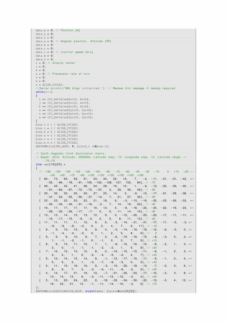
data . x = 0; / / Pos i t i on [m]data . y = 0;data . z = 0;data . a = 0; / / Angular p o s i t i o n . A t t i t u d e [ A? ]data . b = 0;data . c = 0;data . l = 0; / / I n e r t i a l speed [m/ s ]data . m = 0;data . n = 0;i = 0; / / Grav i t y vec to rj = 0;k = 0;u = 0; / / Precession ra te o f t u rnv = 0;w = 0;r = ALIGN_CYCLES ;/ / S e r i a l . p r i n t l n ( ” IMU Al ign i n i t i a l i z e d . ” ) ; / / Remove t h i s message i f memory requ i redwhi le (r−−){
i += I2C_GetValue (AccID , AccX ) ;j += I2C_GetValue (AccID , AccY ) ;k += I2C_GetValue (AccID , AccZ ) ;u += I2C_GetValue (GyroID , GyroX ) ;v += I2C_GetValue (GyroID , GyroY ) ;w += I2C_GetValue (GyroID , GyroZ ) ;
}bias . i = i / ALIGN_CYCLES ;bias . j = j / ALIGN_CYCLES ;bias . k = k / ALIGN_CYCLES ;bias . u = u / ALIGN_CYCLES ;bias . v = v / ALIGN_CYCLES ;bias . w = w / ALIGN_CYCLES ;EEPROMWrite (IMU_ADDR , 6 , (uint8_t * )&bias . i ) ;
/ / Earth magnetic f i e l d d e c l i n a t i o n mat r i x/ / Epoch : 2012 , A l t i t u d e : 250000m, La t i t ude step : 10 , Longi tude step : 15 , La t i t ude range : ←↩
−70,+70char wmm [ 1 5 ] [ 2 5 ] ={
/ / −180 −165 −150 −135 −120 −105 −90 −75 −60 −45 −30 −15 0 +15 +30 ←↩+45 +60 +75 +90 +105 +120 +135 +150 +165 +180
{ 84 , 73 , 65 , 58 , 51 , 43 , 34 , 25 , 16 , 7 , −2, −11, −21, −31, −43, ←↩−55, −66, −78, −91, −105, −124, −128, 127 , 102 , 84} , / / −70
{ 46 , 45 , 43 , 41 , 38 , 34 , 28 , 19 , 10 , 1 , −6, −13, −20, −30, −40, ←↩−51, −60, −67, −72, −72, −57, 3 , 39 , 46 , 46} , / / −60
{ 30 , 30 , 30 , 30 , 29 , 27 , 23 , 14 , 3 , −6, −13, −17, −21, −29, −38, ←↩−47, −53, −55, −50, −37, −14, 7 , 21 , 27 , 30} , / / −50
{ 22 , 22 , 22 , 22 , 22 , 21 , 18 , 9 , −3, −13, −19, −22, −23, −26, −33, ←↩−40, −43, −40, −31, −16, −3, 7 , 14 , 19 , 22} , / / −40
{ 16 , 17 , 17 , 17 , 17 , 16 , 13 , 4 , −8, −18, −23, −24, −22, −19, −23, ←↩−28, −30, −26, −17, −7, 0 , 6 , 11 , 14 , 16} , / / −30
{ 13 , 13 , 14 , 13 , 13 , 12 , 9 , 0 , −12, −20, −23, −22, −17, −11, −11, ←↩−15, −17, −15, −9, −2, 2 , 5 , 8 , 11 , 13} , / / −20
{ 11 , 11 , 11 , 11 , 10 , 9 , 6 , −3, −14, −21, −21, −17, −11, −5, −3, ←↩−6, −9, −8, −4, 0 , 2 , 4 , 7 , 9 , 11} , / / −10
{ 9 , 9 , 10 , 10 , 9 , 8 , 4 , −5, −14, −19, −18, −12, −6, −2, 0 , ←↩−1, −4, −4, −2, 0 , 1 , 2 , 5 , 8 , 9} , / / 0
{ 9 , 9 , 9 , 10 , 9 , 7 , 2 , −6, −15, −18, −15, −8, −3, 0 , 2 , ←↩1 , −1, −2, −1, 0 , −1, 0 , 3 , 7 , 9} , / / +10
{ 8 , 9 , 10 , 11 , 10 , 7 , 1 , −8, −15, −16, −12, −6, −2, 1 , 3 , ←↩2 , 0 , −1, −1, −1, −2, −2, 1 , 5 , 8} , / / +20
{ 7 , 10 , 12 , 13 , 12 , 8 , 0 , −10, −15, −15, −11, −6, −1, 2 , 3 , ←↩3 , 2 , 1 , 0 , −2, −4, −5, −2, 2 , 7} , / / +30
{ 5 , 10 , 14 , 15 , 14 , 8 , −1, −12, −17, −15, −11, −6, −1, 2 , 4 , ←↩5 , 5 , 3 , 1 , −3, −7, −8, −5, 0 , 5} , / / +40
{ 5 , 11 , 15 , 18 , 16 , 9 , −3, −15, −20, −18, −13, −7, −2, 3 , 6 , ←↩8 , 9 , 7 , 3 , −3, −9, −11, −8, −2, 5} , / / +50
{ 4 , 12 , 17 , 21 , 19 , 10 , −7, −21, −25, −23, −17, −10, −3, 3 , 8 , ←↩13 , 14 , 13 , 6 , −3, −11, −13, −10, −3, 4} , / / +60
{ 5 , 13 , 20 , 24 , 22 , 8 , −18, −33, −34, −30, −22, −13, −5, 4 , 12 , ←↩18 , 22 , 21 , 13 , −1, −11, −14, −10, −3, 5} / / +70
} ;EEPROMWrite (DECLINATION_ADDR , s i z e o f (wmm ) , (byte * )&wmm [ 0 ] [ 0 ] ) ;

Serial . println ( ) ;Serial . println ( ”ALIGN SEQUENCE COMPLETED” ) ;Serial . println ( ”CAUTION: s a t e l l i t e should be programmed : ” ) ;Serial . println ( ” Change RESET EEPROM def ine to f a l s e before f l i g h t ” ) ;wh i le ( t r ue ) ; / / S a t e l l i t e programming i s mandatory a t t h i s po in t
}
vo id loop ( ) {whi le ( t r ue ) ;} / / S a t e l l i t e programming i s mandatory a t t h i s po in t
# end i f