![[MS-SFU]: Kerberos Protocol Extensions: Service for User ...... · [MS-SFU]: Kerberos Protocol Extensions: Service for User ... ... and](https://static.fdocuments.in/doc/165x107/5f847f2eababf2788c19203a/ms-sfu-kerberos-protocol-extensions-service-for-user-ms-sfu-kerberos.jpg)
A-MS SERIES USER MANUAL PART1
19
GoodWe Technologies Co., Ltd. No. 90 Zijin Rd., New District, Suzhou, 215011, China www.goodwe.com [email protected] GoodWe Website Local Contacts V1.2-2022-01-05 A-MS Series Grid-Tied PV Inverter User Manual
Transcript of A-MS SERIES USER MANUAL PART1

GoodWe Technologies Co., Ltd.
No. 90 Zijin Rd., New District, Suzhou, 215011, China
www.goodwe.com
GoodWe Website
Local ContactsV1.2-2022-01-05
A-MS SeriesGrid-Tied PV Inverter
User Manual

01 INTRODUCTION
TABLE OF CONTENTS
1.1 Operation Modes Introduction ........................................................................................ 011.2 Safety & Warning ................................................................................................................ 021.3 Product Overview .............................................................................................................. 061.4 User Interface Introduction ............................................................................................... 07
03 OTHERS
3.1 Error Messages .................................................................................................................... 233.2 Troubleshootings ............................................................................................................... 253.3 Disclaimer ............................................................................................................................ 273.4 Technical Parameters ......................................................................................................... 28
3.4.1 Inverter Specification ............................................................................................... 283.4.2Grid Parameter Setting .............................................................................................. 31
3.5 Maintenance ........................................................................................................................ 323.5.1 Fans Clear And Replacement .................................................................................. 323.5.2 About Periodical Maintenance ................................................................................33
02 INSTALLATION INSTRUCTION
2.1 Mounting .............................................................................................................................. 082.1.1 Select Mounting Location ........................................................................................ 082.1.2 Wall Mounted Bracket And Inverter Installation ................................................... 09
2.2 Conduit Wiring And Installation ........................................................................................ 112.2.1 Wiring Box Conduit Plugs ......................................................................................... 122.2.2 PV Wiring Connection ............................................................................................... 132.2.3 On-Grid Connection .................................................................................................. 162.2.4 CT Connection ........................................................................................................... 172.2.5 WiFi Communication Connection .......................................................................... 18
2.3 PV Master App .................................................................................................................... 182.4 Inverter Arc Detection In A-MS ......................................................................................... 192.5 System Connection Diagram ............................................................................................ 212.6 Wiring System ...................................................................................................................... 22

01 INTRODUCTION
1.1 Operation Modes Introductionprovides energy management in a PV system that includes solar modules and utility grid
connection. Energy produced by the PV system is used to be exported to the grid.
DANGER indicates a hazardous situation which, if not avoided, will result in death or serious injury.
DANGER indique une situation dangereuse qui, si elle n’est pas évitée, est susceptible de provoquer un décès ou des blessures graves.
WARNING indicates a hazardous situation which, if not avoided, could result in death or serious injury.
AVERTISSEMENT indique une situation dangereuse qui, si ellen’est pas évitée, est susceptible de provoquer un décès ou des blessures graves.
CAUTION indicates a hazardous situation which, if not avoided, could result in minor or moderate injury.
PRUDENCE indique une situation dangereuse qui, si elle n’est pas évitée, est susceptible de provoquer des blessures légères ou de degré moyen.
Danger of high voltage and electric shock!
Danger de haute tension et de choc électrique !
Components of the product can be recycled.
Les composants du produit peuvent être recyclés.
This side up! The package must always be transported, handled and stored in such a way as the arrows always point upwards.
Ce côté vers le haut! Le paquet doit toujours être transporté, manipulé et stocké de manière à ce que les flèches pointent toujours vers le haut.
Hot Surface- To reduce the risk of burns-Do not touch.
Surface chaude- Pour réduire le risque de brûlures- Ne touchez pas
No more than six (6) identical packages being stacked on each other.
Pas plus de six (6) paquets identiques étant empilés les uns sur les autres.
Products should not be disposed as household waste.
Les produits ne doivent pas être éliminés comme déchets ménagers.
Symbols Explanation
DANGER!DANGER!
WARNING!AVERTISSEMENT!
WARNING!AVERTISSEMENT!
CAUTION!PRUDENCE!
1.2 Safety & WarningA-MS series inverter from GoodWe Technologies Co., Ltd. (Herein after known as Goodwe) has been designed and tested in accordance with safety requirements. As with power electronic devices, there are residual risks despite strict standards. You are recommended to read the following information carefully to prevent personal injury and property damage.
SAVE THESE INSTRUCTIONS - This manual contains important instructions for A-MS INVERTER that shall be followed during installation and maintenance of the inverter.
These servicing instructions are for use by qualified personnel only. To reduce the risk of electric shock, do not perform any servicing other than that specified in the operating instructions.
Ces instructions d’entretien sont destinées uniquement au personnel qualifié. Pour réduire le risque de choc électrique, n’effectuez aucun service autre que celui spécifié dans les instructions d’exploitation.
PV string
Rapid shutdown switch
Inverter
Load
PV Master App
Grid
0201
03
Do not open the inverter's cover or change any components without manufacturer's authorization, otherwise the warranty commitment for the inverter will be invalid.
N’ouvrez pas la couverture de l’onduleur ou ne modifiez aucun composant sans l’autorisation du fabricant, sinon l’engage-ment de garantie pour l’onduleur sera invalide.
Usage and operation of the inverter must follow instructions in this user manual, otherwise the protection design might be impared and warranty commitment for the inverter will be invalid.
L’utilisation et le fonctionnement de l’onduleur doivent suivre les instructions contenues dans ce manuel d’utilisation, sinon la conception de protection pourrait être imparée et l’engagement de garantie pour l’onduleur sera invalide.
Appropriate methods must be adopted to protect inverter from electrostatic damage. Any damage caused by static is not warranted by manufacturer.
Des méthodes appropriées doivent être adoptées pour protéger l’onduleur contre les dommages électrostatiques. Tout dommage causé par statique n’est pas justifié par le fabricant.
PV negative (PV-) on inverter side is not grounded as default design. Connecting PV- to EARTH IS strictly forbidden.
Le pôle PV négatif (PV-) du côté de l'onduleur n'est pas mis à la terre comme conception par défaut. Il est strictement interdit de connecter PV- à EARTH.
PV modules used on the inverter must have an IEC61730 class A rating, and the total open-circuit voltage of PV string/ar-ray is lower than the maximum rated DC input voltage of the inverter. Any damage caused by PV over-voltage is beyond warranty.
Les modules photovoltaïques utilisés sur l’onduleur doivent avoir une cote de classe A IEC61730, et la tension totale en circuit ouvert de la chaîne/tableau PV est inférieure à la tension d’entrée DC nominale maximale de l’onduleur. Tout dommage causé par la surtension PV est au-delà de la garantie.
The inverter has built-in RCMU and may produce DC residual current of no more than 6mA. An external Type A RCD (with operating current ≥30mA) can be used if required.
L’onduleur a intégré RCMU et peut produire DC courant résiduel d’au plus 6mA. Un RCD externe de type A (avec courant d’exploitation de 30mA) peut être utilisé si nécessaire.
Before connecting the A-MS series inverter to the AC distrubution grid, approval must be received by the appropiate local utility as required by national and state interconnection regulations.
Avant de connecter l’onduleur de la série A-MS au réseau de distrubution AC, l’approbation doit être reçue par l’utilité locale appropiate comme l’exigent les règlements nationaux et d’interconnexion de l’État.
All electrical installations must be carried out in accordance with the local electrical standards and the National Electrical Code ANSI/NFPA 70 or the Canadian Electrical Code CSA C22.1.Before connecting the inverer to the grid, contact your local grid operator. The electrical connection of the inverter must be carried out by qualified personnel only.
Toutes les installations électriques doivent être effectuées conformément aux normes électriques locales et au Code national de l’électricité ANSI/NFPA 70 ou au Code canadien de l’électricité CSA C22.1.Avant de raccorder l’inverer au réseau, communiquez avec votre opérateur de réseau local. La connexion électrique de l’inverer ne doit être effectuée que par des personnes de quelifief.
When exposed to sunlight, the PV array generated dangerous DC voltage which is presented in the DC conductors amond the live compoents can lead to lethal electric shocks. If you unplug the terminal plate with the connected DC conductors from DC in slot under load, an electric arc may occur, which can cause an electric shock and burns.
Lorsqu’il est exposé à la lumière du soleil, le tableau PV généré tension DC dangereux qui est présent dans les conducteurs DC amond les compoents vivants peuvent conduire à des chocs électriques mortels. Si vous débranchez la plaque terminale avec les conducteurs DC connectés de DC dans la fente sous charge, un arc électrique peut se produire, ce qui peut causer un choc électrique et des brûlures.
Safety WarningsAny installation and operation on inverter must be performed by qualified electricians, in compliance with standards, wiring rules or requirements of local authorities or grid company.
Toute installation et fonctionnement sur onduleur doivent être effectués par des électriciens qualifiés, conformément aux normes, aux règles de câblage ou aux exigences des autorités locales ou de la société de réseau.
The input and output circuits are isolated from the enclosure and that system grounding, if required by Sections 690.41, 690.42 and 690.43 of the National Electric Code, ANSI/NFPA 70, is the responsibility of the installer.
Les circuits d’entrée et de sortie sont isolés de l’enceinte et cette mise à la terre du système, si nécessaire par les sections 690.41, 690.42 et 690.43 du Code national de l’électricité, ANSI/NFPA 70, est la responsabilité de l’installateur.
Any operation on AC or DC terminals when inverter is operational is prohibited
Toute opération sur le terminal AC ou DC lorsque l’onduleur est en service est interdite.
Before any wiring connection or electrical operation on inverter, all DC and AC power must be disconnected from inverter for at least 5 minutes to make sure inverter is totally isolated to avoid electric shock.
Avant toute connexion de câblage ou de fonctionnement électrique sur onduleur, toute la puissance DC et AC doit être déconnectée de l’onduleur pendant au moins 5 minutes pour s’assurer que l’onduleur est totalement isolé pour éviter les chocs électriques.
The temperature of inverter surface might exceed 60℃ during operation, so please make sure it has cooled down before touching it, and make sure the inverter is out of reach of children.
La température de la surface de l’onduleur peut dépasser 60 oC pendant l’opération, alors assurez-vous qu’elle s’est refroidie avant de la toucher, et assurez-vous que l’onduleur est hors de portée des enfants.
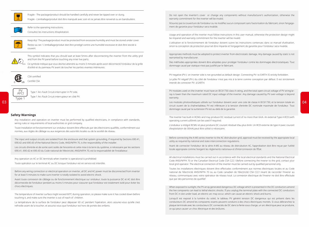
Fragile - The package/product should be handled carefully and never be tipped over or slung.
Fragile - L’emballage/produit doit être manipulé avec soin et ne jamais être renversé ou en bandoulière.
Refer to the operating instructions.
Consultez les instructions d’exploitation.
Keep dry! The package/product must be protected from excessive humidity and must be stored under cover.
Restez au sec ! L’emballage/produit doit être protégé contre une humidité excessive et doit être stocké à couvert.
This symbol indicates that you should wait at least 5mins after disconnecting the inverter from the utility grid and from the PV panel before touching any inner live parts.
Ce symbole indique que vous devriez attendre au moins 5 minutes après avoir déconnecté l’onduleur de la grille d’utilité et du panneau PV avant de toucher les parties vivantes intérieures.
CSA certified
Certifié CSA
5min
PVAFCI
Type 1
Type 1 Arc-Fault Circuit-interrupter in PV side.
Type 1 Arc-Fault Circuit-interrupteur en côté PV.
0403

Do not touch non-insulated conductors.
Ne touchez pas les conducteurs non isolés.
Do not touch the DC conductors.
Ne touchez pas les conducteurs de DC.
Do not touch any live compoents of the inverters.
Ne touchez pas à des compoents vivants des onduleurs.
Any equipment damage caused by incorrect cable connections is not covered by the warranty.
Tout dommage causé par des connexions incorrectes au câble n’est pas couvert par la garantie.
Operation personnel must wear proper PPE all the time when connecting cables.
Le personnel d’exploitation doit porter l’EPI approprié tout le temps lors de la connexion des câbles.
Incorrect installation of conduit may cause a water-proofing problem.
L’installation non décorative du conducteur métallique peut causer un problème imperméable à l’eau.
Class 1 wiring methods are to be used for field wiring connections to terminals of a Class 2 circuit.
Les méthodes de câblage de classe 1 doivent être utilisées pour les connexions de câblage sur le terrain aux terminaux d’un circuit de classe 2.
AC output (neutral) is not bonded to ground.
La sortie d’AC (neutre) n’est pas collée au sol.
To reduce the risk of fire, please add an overcurrent protection device (OCPD or ‘circuit breaker’) in accordance with the National Electrical Code ANSI / NFPA 70.
Pour réduire le risque d’incendie, veuillez ajouter un disjoncteur de protection trop courant conformément au Code National d’Électricité ANSI / NFPA 70.
The inverter is not provided with an isolation transformer and is intended to be installed per NFPA 70, 690.35 with an ungrounded PV array.
L’onduleur n’est pas équipé d’un transformateur d’isolement et est destiné à être installé par NFPA 70, 690,35 avec un tableau PV non solé.
A transmitter meeting the SUNSPEC protocol is integrated in A-MS series inverters and has obtained CSA certification. It is compatible with Rapid Shut-Down devices in the marketplace that comply with the SUNSPEC protocol; together they form a system that meets the requirements of NEC 2017 regulation.
Un émetteur qui répond au protocole SUNSPEC s’est intégré dans les onduleurs de stockage d’énergie de la série A-MS . Déjà terminé des tests en laboratoire de l’ASC et obtenu des certifications. Il peut être compatible avec le dispositif Rapid Shut-Down sur le marché qui est conforme au protocole SUNSPEC, ensemble pour accomplir un système qui répond aux exigences de la réglementation NEC2017.
1.3 Product Overview
Note:
[1] DC switch: DC switch is used to shut down the PV system in case of emergency. And also avoid electric shock when wiring and maintenance. It also can be used as RSD (Rapid Shutdown) switch.
[2] EMS: Used to upgrade programs and communicate with third-party monitoring software。
Grounding (PE) busbar
Energy Meter CT terminal (Meter)Hole for connecting cable
Port for connecting WiFi Module
EMS (EMS) [2]
On-Grid terminal (GRID)
DC switch[1]
Ground bar
Hole for connecting cable
PV input terminal (PV INPUT)
LED IndicatorsWi-Fi
Reset/Reload
0605

15°
For inverter's protection and convenient maintenance, mounting location for inverter should be selected carefully based on the following rules:
Rule 1. Any part of this system shouldn't block the switch and breaker from disconnecting the inverter from DC and AC power.
Rule 2. Inverter should be installed on a solid surface, where it is suitable for inverter's dimen-sions and weight.
Rule 3. Inverter should be installed vertically or lie on a slope by a max of 15°.
2.1 Mounting2.1.1 Select Mounting Location
Keep away from sunlight Keep dry Keep it clear of snow Sun Rain Accmulated snow
Rule 4. Ambient temperature should be lower than 45°C. (High ambient temperature will cause power derating of inverter.)
Rule 5. The inverter can be installed outdoors, do not install the inverter indoors.
Rule 5. It is recommanded that the installation of the inverter should be prevented from direct sunlight, snow, rain and other negative influences which may cause function impact or life aging.
Rule 6. Inverter should be installed at eye level for convenient maintenance.Rule 7. Product label on inverter should be clearly visible after installation. Do not damage the
lable.Rule 8. Do not install the inverter when it is snowing or raining. If you have to, pay attention to
the waterproof and moisture-proof of the inverter and distribution box.Rule 9. Leave enough space around the inverter according to the below figure for natural heat
dissipation.
1.4 User Interface Introduction INSTALLATION INSTRUCTIONS02
Wi-Fi reset: Wi-Fi reset means restarting Wi-Fi module. Wi-Fi settings will be reprocessed and saved automatically.
Short press reset button.
Wi-Fi LED will blink for a few seconds.
Wi-Fi reload: Wi-Fi Reload means setting Wi-Fi module back to default factory setting.
Long press reset button (longer than 3s).
The Wi-Fi LED will double blink until the WiFi configuration is reloaded.
Note:WiFi reset and reload functions are only used when:1. Wi-Fi loses connection to internet or cannot connect to PV Master App successfully.2. Cannot find "Solar-WiFi signal" or have other Wi-Fi configuration problems.3. Please do not use this button if Wi-Fi monitoring works well.
0807

Avoid drilling holes in walls with cables inside or on the back.
Évitez de percer des trous dans les murs qui avec des câbles à l’intérieur ou à l’arrière.
WARNING!AVERTISSEMENT!
Carry the inverter by holding the heatsink on two sides and place the inverter on the wall-mounted bracket. The inverter is heavy, do not carry it by one person.
Step 3
Bearing capacity of the wall must be higher than 100kg(220.46lb), otherwise it may not be able to prevent the inverter from dropping.
La capacité de roulement du mur doit être supérieure à 100 kg(220.46lb), sinon elle pourrait ne pas être en mesure d’empêcher
l’onduleur de tomber.
Do not use force beyond the heatsink sides to avoid damage to the inverter.
Avoid holding and lifting the wiring box, keep balance of the inverter during moving.
N’utilisez pas la force au-delà des côtés du radiateur pour éviter les dommages causés à l’onduleur.
Évitez de tenir et de soulever l’unité de connexion, de maintenir l’équilibre de l’onduleur pendant le déplacement.
WARNING!AVERTISSEMENT!
WARNING!AVERTISSEMENT!
Use expansion bolts in accessory box to fix the wall-mounted bracket onto the wall tightly.
Step 2
110mm 120mm
120mm
70mm 70mm
150m
m
Wall -mounted bracket Expansion bolts200mm
Step 1
415mm
DANGER!DANGER!
Upward----------Downward------Front-------------Both sides-------
500mm300mm300mm200mm
200mm 300mm
300mm
500mm
2.1.2 Wall Mounted Bracket And Inverter InstallationInverter should be installed away from combustible, explosive and strong electro-magnatic materials.The inverter is suitable for mounting on non-combustible surface only.L’onduleur doit être installé loin des matériaux électro-magnats combustibles, explosifs et forts.L’onduleur est adapté pour au montage sur une surface non combustible seulement.
Take out the mounting template which is to locate the hole position of the wall mounted brackets.Fix the mounting template on the wall which is suitable for installation of invert-er. Please drill 7 holes on the wall according to the size on the frame post.(8mm*1 in diameter, and 80mm*2 in depth).
791m
m
192mm
175mm
70mm 70mm
110mm 120mm
120mm
359mm
150mm
(7.87 in.) (7.87 in.)
(7.87 in.)
(11.81 in.) (11.81 in.)(11.81 in.)
(19.69 in.)
(19.69 in.)
(11.81 in.)
(16.34 in.)
(31.
14 in
.)
(7.56 in.)
(6.89 in.)
(4.33 in.)(4.72 in.)
(4.72 in.)
(5.91 in.)
(2.76 in.)(2.76 in.)
(14.13 in.)
*1. 10mm=0.39 in.*2. 80mm=3.15 in.
(5.
91 in
.)
(2.76 in.)(2.76 in.)
(4.33 in.)(4.72 in.)
(4.72 in.)
1009

Step 6
Step 5
2.2 Conduit and Wiring InstallationBefore starting installation or commissioning A-MS , please read the following statements carefully.
• During wiring connection, the operator should always wear proper PPE.
• "Intallation and commissioning must be performed by qualified personnel in accordance with local, state, and National Electrical Code ANSI/NFPA 70 requirements.
• The method and process of installing and wiring connection must
comply with all US National Electric Code (NEC) requirement and local AHJ inspector requirements in the United States. Meanwhile in Canada, method and process must comply with Canadian Electric
Inverter can be locked for prevention of thievery. Lock will not be provided by inverter manufacturer.
DC switch should be in "OFF" position during installation and maintenance. A lock can be applied to prevent wrong operation.
DANGER!DANGER!
Step 4
Fasten the inverter by fixed screws.(3
positions)
Code: Part I and Part II, and the local AHJ inspector requirements.
• The wiring installation must strictly observe correct specification. Otherwise, it may bring waterproof and electrical problems.
• Avant de commencer l’installation ou la mise en service de A-MS, veuillez lire attentivement les déclarations ci-dessous.
• Pendant la connexion au câblage, l’opérateur doit toujours porter un EPI approprié.
• L’installation et la mise en service doivent être effectuées par un électricien agréé conformément aux exigences locales, étatiques et nationales du Code électrique ANSI/NFPA 70.
• La méthode et le processus d’installation et de connexion au câblage doivent se conformer à toutes les exigences du Code national électrique (NEC) des États-Unis et aux exigences locales des inspecteurs de l’AHJ dans les États-Unis. Pendant ce temps, au Canada, la méthode et le processus doivent être conformes au Code canadien de l’électricité : partie I et partie II, ainsi qu’aux exigences locales des inspecteurs de l’AHJ.
• L’installation de câblage doit observer strictement les spécifica-tions correctes. Sinon, il peut apporter des problèmes imper-méables et électriques.
Step 1
Undo the 4 screws of the connection box cover with the included Allen Wrench and remove the cover.
2.2.1 Wiring Box Conduit PlugsConduit plugs are provided for 1”diameter conduit fittings. An appropriate conduit adaptor or reducing washers should be applied when conduit fittings with other dimensions are used.
DANGER!DANGER!
4mm(0.16 in.)
1211

2.2.2 PV Wiring ConnectionBefore PV wiring connection, please read this section carefully.
• The total short-circuit current of PV string must not exceed inverter's maximum DC short-circuit current.
• Positive and negative poles of PV strings should not be grounded.
• Conductor size should be no less than #12 AWG due to no internal PV circuit current protection device.
• For the minimum isolation resistance to ground of the PV string, please refer to the below table.
Avant la connexion de câblage PV, s’il vous plaît lire cette section attentivement.
• Le courant de court-circuit total de la chaîne PV ne doit pas dépasser le courant de court-circuit DC maximal de l’onduleur.
• Les poteaux positifs et négatifs des cordes photovoltaïques ne doivent pas être cloués à la terre.
• Les spécifications des conducteurs ne doivent pas être inférieures à celle d’12 AWG en raison de ne pas être reliée au fusible.
• Pour la résistance minimale à l’isolement au sol de la chaîne PV, veuillez consulter le tableau ci-dessous.
WARNING!AVERTISSEMENT!
Step 2
Step 3
Inverter model
GW5000A-MS
GW6000A-MS
GW7000A-MS
GW7600A-MS
GW8600A-MS
GW9600A-MS
Minimum isolation resistance
600kΩ
500kΩ
430kΩ
395kΩ
350kΩ
313kΩ
B
A
C Grade
A
B
C
Description
Conductor core section
Conductor core length
Outside Diameter
Value
12AWG
18mm(0.71 in.)
Max 5.6mm(0.22 in.)
PV wiring connection process
Please use 90℃ wire, 12AWG Copper.
Do not use aluminum cables .
If using stranded wires, select a proper size wire ferrule (included in accessories box) for the PV input circuits. Crimp the wire ferrules onto the conductors tightly.Note:
Make sure the cable jacket is not locked within the wire ferrule’s crimped section.
It is not necessary to utilize a wire ferrule if using a solid (non-stranded) conductor, just remove the insulation.
Step 1
TerminalCable
Step 2
Run the PV conductors through one or more conduit openings on the left side of the inverter as pictured.Connect the PV conductors to the PV terminals.
• For 5kW/6kW models, one can connect up to 2 PV circuits (4 conductors).
• For 7/7.6/8.6/9.6kW models, one can connect up to 4 PV circuits (8 conductors). PV INPUT
1+ 1- 2+ 2- 3+Don’t connect, for the 5kW/6kW inverter
3- 4+ 4-Note: For inverter 5kW /6kW, do not connect PV cables to Port 3+ /3- /4+ /4-.
Remove the waterproof cover(s) with the included cap removal tool. Remove only those covers on conduit holes to be filled with conduit and fittings.
Insert the desired conduit or tubing and corresponding adaptors, fittings, and bushings, as appropriate. Tighten theconnection.
1413

The polarity of PV strings cannot be connected reversely, otherwise the inverter could be damaged.
Do not connect multiple PV inputs in parallel. If required, add a fuse outside or a breaker which observes safety specification.
The output circuit of PV strings may have dangerous voltage. Touch-ing theses conductors may cause electric shock.
Before connecting them to the PV input terminal, please make sure the DC switch is turned off and there is no voltage at the terminals of DC input conductors
To avoid electric shock when the A-MS is running, do not operate on the PV input terminals, such as connecting or disconnecting the PV strings or PV module in the PV strings
Le terminal de sortie du module PV peut exsister la tension dangere-use. Toucher le terminal peut provoquer un choc électrique. Avant de connecter le terminal d’entrée PV, assurez-vous que l’interrupteur DC est éteint et qu’il n’y a pas de tension dans les terminaux des produits d’entrée DC.
Lorsque A-MS est en cours d’exécution, ne pas fonctionner sur les terminaux d’entrée PV en cas de choc électrique, comme la connex-ion ou la déconnexion des chaînes photovoltaïques ou du module PV dans les chaînes photovoltaïques.
Make sure the equipment grounding wires from PV arrays are connected to one of the GND/PE bus bars and that these bus bars have a stable, bonded, and low resistance path to a grounding electrode conductor.
Assurez-vous que la ligne de sol de GND est reliée au point de terrassement et à la connexion stable entre le cadre du module PV et le point de terrassement.
Do not remove the waterproof bolt from any PV input terminals not being used. Doing so may affect the IP/MEMA rating of your A-MS inverter.
N’enlevez pas le boulon imperméable à l’eau des terminaux d’entrée DC si les terminaux d’entrée DC d’A-MS ne sont pas connectés aux chaînes photovoltaïques. Dans le cas contraire, il peut affecter le niveau de propriété intellectuelle de A-MS .
WARNING!AVERTISSEMENT!
DANGER!DANGER!
2.2.3 On-Grid / AC ConnectionAn external AC breaker, usually located in a load panel or solar dedicated AC sub-panel, is needed for an on-grid / AC connection to isolate the inverter from the utility grid when neces-sary.
Specifications of AC breaker used for different inverter model are advised. Please read the following table and local requirement before selecting a suitable AC breaker.
Inverter model
GW5000A-MS
GW6000A-MS
GW7000A-MS
GW7600A-MS
GW8600A-MS
GW9600A-MS
Max Ampacity Breaker Rating
35A
40A
45A
50A
50A
50A
Note: The absence of AC breaker will lead to inverter damage if an electrical short circuit happens on grid side.
DANGER!DANGER!
Make sure the inverter is totally isolated from any DC or AC power before connecting AC cable.Assurez-vous que l’onduleur est totalement isolé de toute puissance DC ou AC avant de connecter le câble AC.
Inverter model
GW5000A-MS
GW6000A-MS
GW7000A-MS
GW7600A-MS
GW8600A-MS
GW9600A-MS
Conductor Core Section (Recommended)
10AWG
10AWG
8AWG
8AWG
8AWG
8AWG
Please use 90°C, #8-10 AWG copper building wire.
Do not use aluminum cables .
18mm
Conductor CoreSection
Maximum outside diameter 7.4mm(0.29 in.)
Use the correct wire ferrule from the accessory box. Crimp the ferrule onto the conductor core tightly, as shown below.Note:
Make sure the cable jacket is not locked within the wire ferrule’s crimped section. It is not necessary to utilize a wire ferrule if using a solid (non-strand-ed) conductor, just remove the insulation.
Step 1
TerminalCable
(0.71 in.)
1615

GRIDN L1 L2
Step 2
Run the AC conductors (N, L1, L2) through a conduit opening located either below or to the right of the GRID terminals. Connect AC conductors to GRID terminals.
If connecting CT’s to the line side of the main break, make sure the AC conductors (L1 and L2) are totally isolated from AC power before connecting a CT to each.Assurez-vous que le câble AC est totalement isolé de la puissance AC avant de connecter CT.
2.2.4 CT ConnectionsThe two split-core current transformers (CTs) in product box must be installed for the system to detect AC Mains current direction and magnitude; this data instructs the operation of GEH inverter based on operating mode.Note:1. The Smart Meter with CT is well configured, please do not change any setting on the Smart Meter.2. Each CT must be connected on a separate phase (e.g., L1 and L2)3. Please use only the 2 CTs in the accessory box.4. The CT cable is 10m (32.8 ft) as default.5. CT cable can be extended to a maximum of 30m (98.4 ft), contact the support department to
achieve the maximum cable length.
DANGER!DANGER!
Connect CT1 and CT2 in the accessories to the corresponding line at the entrance.
Step 1
PEN
L2L1
Grid
Load
CT 1 connect to L1CT 2 connect to L2
CT 2CT 1
Power Meter
Step 2
Pass the other end of the CT through the CT port and insert the 4-Pin terminal to the "Connect to CT"
Connect to CT
2.3 PV Master AppPV Master is an external monitoring/ configuration application for inverters, used on smart phones or tablet for both Android and iOS system. Main functions are as below:
1. Edit system configuration to make the system work as customer needs.
2. Monitor and check the performance of the system.
3. Wi-Fi configuration.
Please download "PV Master App" from www.goodwe.com or scan the QR code on the back of this user manual.
95048EHU123456784:21 PM 100%VIRGIN
Waiting
Safety Country
Battery Type
Operation Model
Meter Communication Status
BMS Communication Status
Back-Up Switch
Anti-Reverse Function Switch
English
Battery-Box H6.4
Normal
CT connection
Alarm warning
On
Off
Overview Param Set
0.00(kW)0.00(kW)
0.00(kW)
0.00(kW)
?
2.2.5 WiFi Communication ConnectionAfter completing installation and wiring connection, please refer to “WiFi Configuration Instructioin” in the accessory box to complete the WiFi configuration.
Plug the WiFi module into the Wifi terminal.
Grid side
1817

Use of the arc detection function
In North America, according to UL / CSA (UL1699B) safety requirements regarding arc, it is necessary to detect and terminate the arc by shutting down the inverter.
The AFCI function is integrated in the A-MS series inverter. Once an arc is detected, the corresponding error and time will be reported in the App. The first 4 faults of the inverter within 24 hours can be resolved by automatic recovery or manual recovery. After the 5th arc fault the inverter must be stopped. Only after the site troubleshooting or the problem components are replaced, and the fault error is manually cleared, can the machine work normally.
AFCI function needs to be operated in PV Master App:
2.4 Arc DetectionAFCI function in A-MS
An electric arc is a gas discharge phenomenon. An instantaneous spark caused by an electric current passing through some insulating medium (such as air).
The cause of the electric arc
• Connector is not connected well in photovoltaic system• Incorrect or broken cable connection• Deterioration of connectors and cables due to aging of photovoltaic systems
DANGER!DANGER!
Arcs generate heat which can cause fires and they also pose an electrocution risk to those working near them.
Les arcs génèrent de la chaleur qui peut causer des incendies et ils présentent également un risque d’électrocution pour ceux qui travaillent près d’eux.
Turn on Arc detection function:
“Settings→ Advanced Setting→ Arc
detection→ Arc detection”.
Self checking function: “Settings→
Advanced Setting→ Arc detection→
Self checking”. After the self-test is
completed, the test result will be
displayed in the "Arcing self-test
status".
Clear arcing alarm function: “Settings
→ Advanced Setting→ Arc detection→
Clear arcing alarm”
Arc decection
Arcing detection status:
Clear arcing alarm
Self checking
Not self-checking
Set
Set
Arc detection
Arc decection
Arcing detection status:
Clear arcing alarm
Self checking
Not self-checking
Set
Set
Arc detection
Arc decection
Arcing detection status:
Clear arcing alarm
Self checking
Not self-checking
Set
Set
Arc detection
2019
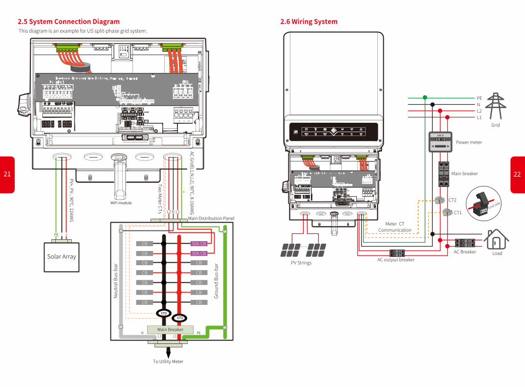
2.5 System Connection Diagram 2.6 Wiring SystemThis diagram is an example for US split-phase grid system.
PV+, PV-, 90℃, 12AW
G
Solar Array
L1L2N
To Utility Meter
Main Breaker
Main Distribution Panel
CB
CB
CB
CB
CB
CB
CB
50A CB
CB
CB
CB
CB
CB
50A CB
Two Meter CTs
CT1CT2
PE
Neut
ral B
us-b
ar
Grou
nd B
us-b
ar
WiFi module
AC Grid[L1,N,L2], 90℃, 8-10AW
G
PE - +
L2 N L1
PV Strings
CT1
AC output breakerLoadAC Breaker
PENL2L1
Grid
Power meter
Main breaker
CT2Grid side
......
Meter CT Communication
2221

3.1 Error MessagesThe error messages below will be displayed on PV Master App or reported by e-mail if an error occurs.
03 OTHERS
ERROR MESSAGE EXPLANATION REASON SOLUTIONS
Check (use multi-meter) if there is voltage (normally should be close to 0V) between earth & inverter frame. If there is a voltage, it means the neutral & ground cables are not connected well on the AC side. If it happens only in the early morning/dawn /rainy days with higher air humidity and is recovered soon, it should be normal.
Check (use multi-meter) if there is high voltage (normally should be lower than 10V) between N & PE cable on the AC side. If the voltage is higher than 10V, it means the Neutral & ground cable are not connected well on AC side or restart inverter.
1. Check (use multi-meter) if AC side has voltage . Make sure grid power is available.2. Make sure AC cables are connected tightly and well.3. If all is well, please try to turn off AC breaker and turn on again in 5 mins.
1. Make sure safety country of the inverter is set right.2. Check (use multi-meter) if the AC voltage (Between L & N) is within a normal range (also on AC breaker side)
a. If the AC voltage is high, then make sure the AC cable complies with that required on user manual and the AC cable is not too long.b. If the voltage is low, make sure the AC cable is connected well and the jacket of the AC cable is not compressed into the AC terminal.
3. Make sure the grid voltage of your area is stable and within normal range.
1. Make sure the safety country of the inverter is set right.2. If safety country is right, then please check on the inverter display if AC frequency (Fac) is within a normal range.3. If FAC failure only appears a few times and is resolved soon, it should be caused by occasional grid frequency unstability.
1. Try to decrease surrounding temperature.2. Make sure the installation complies with the instruction on inverter user manual.3. Try to close the inverter for 15 mins, then start up again.
1. Use multi-meter to check if the resistance between earth & inverter frame is close to zero. If it's not, please ensure that the connection is well.2. If the humidity is too high, isolation failure may occur.3.Check the resistance between PV1+/PV2+/PV3+/PV4/PV- to earth. If the resistance is lower than the minimum isolation resistance shown in the
table( chapter 2.4.2 ) , check the system wiring connection.4. Try to restart the inverter.Check if the fault still occurs. If not, it means it is caused by an occasional situation, or contact after-sales.
Try to restart the inverter,check if it still occurs.If not,it is just an occasional situation.Otherwise, contact after-sales immediately.
Try to restart the inverter,check if it still occurs.If not,it is just an occasional situation.Otherwise, contact after-sales immediately.
Try to restart the inverter,check if it still occurs.If not,it is just an occasional situation.Otherwise, contact after-sales immediately.
Try to restart the inverter,check if it still occurs.If not,it is just an occasional situation.Otherwise, contact after-sales immediately.
Try to restart the inverter, check if it still occurs. If not, it is an occasional situation. Otherwise , contact after-sales immediately.
1. If it is the first time this problem has occurred, clear arc fault by App and restart the inverter. If not, it means it is caused by an occasional situation.2. If the problem persists, check whether connectors or cables in a PV system are improperly connected or are damaged. Unplug all the wires and reconnect or replace the damage cable, than start the inverter. Check if the fault still occurs, contact after-sales.
Try to restart the inverter. Check if the fault still occurs. If not, it means it is caused by an occasional situation,or contact after-sales.
Public grid power is not available (power lost or on-grid connection fails)
PV voltage is too high
Ground leakage current is too high
The total voltage (open-circuit voltage) of each PV string is higher than the max DC input voltage of the inverter.
Utility Loss
VAC Failure
Isolation Failure
Ground I Failure
Relay Check Failure
Grid voltage is not within permissible range
Grid frequency is not within permissible range
Temperature inside of the inverter is too high
Self checking of relay failure
Internal communication failure
BUS voltage is over-high
The inverter's AC HCT check failure.
AFCI module detected a failure.
GFCI Device Check Failure
Inverter detects that AC voltage is beyond the normal range required by the safety country
Inverter does not detect the connection of grid
Inverter detects that the grid frequency is beyond the normal range required by the safety country
The inverter's working environment leads to a high temperature condition
Ground insulation impedance of PV string is too low
Isolation failure could be caused by multiple reasons like that the PV panels are not grounded well, DC cable is broken, PV panels are aged or surrounding humidity is comparatively heavy, etc.
Neutral & ground cables are not connected well on AC side or just an occasional failure
The inverter detects a higher DC component in AC output
Caused by a strong external magnetic field etc.
Caused by a strong external magnetic field etc.
Inverter hardware current sensor failure.
AFCI self-test is abormal or an arc occurs on the PV terminal of the inverter.
GFCI device failure
Ground failure could be caused by multiple reasons like that the neutral cable on the AC side is not connected well or the surrounding humidity is comparatively heavy, etc.
/
/
/
DC Injection High
EEPROM R/W Failure
SPI Failure
DC Bus High
AC HCT Check Failure
AFCI Fault
GFCI Device Check Failure
FAC Failure
PV Over Voltage
Over Temperature
Check if PV string Voc is lower than Max PV input voltage of the inverter.If Voc of PV string is high, please decrease panels to make sure Voc is within the max DC input voltage of the inverter.
2423

3.2 Troubleshootings
A-MS not started up with PV only
Solution:
1. Make sure the voltage of PV is highter than 100V(need 150 V to enter on-grid mode ).
2. Make sure the connection between A-MS and PV panels:polarities are (+/-)not reversed.
Problems During Operation
Safety code:
After connecting Solar-WiFi* (*The Wi-Fi signal is named the last 8 characters of the inverter's serial No.), check on PV Master App "Parameters" to make sure the "Safety Code" Setting is right. Please set it right in "Settings" if the setting is not right.
Checking As Start A-MS Up And Turn On AC Power
Questions & Answers (Q & A)
About Wi-Fi Configuration
Q: Why can't I connect Solar-WiFi* signal on my phone?
A: The WiFi module can only connect to one device at a time. If the signal is already connected to another device at the time for some reason, you cannot connect to the signal.
About PV Master Operation And Monitoring
Q: Why can't I save settings on PV Master App?
A: It could be caused by losing connection to Solar-WiFi *.
1. Make sure you have already connected Solar-WiFi* (make sure no other devices connected) or router (if connected Solar-WiFi* to router). App's homepage shows connection well.
2. Make sure you restart inverter 10mins after you change some settings because inverter will save settings every 10 mins under normal mode. We recommend to change setting parame-ters when inverter is in wait mode.
Q: Why are the data displayed on the homepage different from the param page, like PV value or grid value?
A: The data refresh frequency is different, so there will be a data inconformity between different pages on App as well as between these on portal and App.
Q: Some columns show NA, why does that happen?
A: NA means App does not receive data from inverter or server because of communication problem, such as communication between inverter and the App.
About Smart Meter And Power Limit Function
Q: How to activate output power limit function?
A: For A-MS system, the function could be realized by:
Turn on export power limit function and set the max output power to grid on App.Note: Even if output power limit is set to 0W, there might still be a deviation of a max of 100W export-ing to grid.
Q: Why is there still power exporting to grid after I set power limit as 0W?
A: Export limit could be 0W theoretically, but there will be a deviation of around 50-100W for A-MS system.
Q: Can I use other brand CT to take over in A-MS system?
A: No, because the CT ratio and Meter are well matched, the accuracy and data accuracy cannot be guaranteed by replacing with other CT
Q: What is the maximum current allowed to go through CT on Smart Meter?
A: The max current for CT is 200A.
Other Questions
Q: Is there a quick way to make the system work?
A: For the shortest way, please refer to "A-MS Quick Installation Instructions" and "PV Master App Instruction".
Q: Will the warranty of the inverter still be valid if for some special conditions we cannot 100% follow the user manual instructions on the installation or operation?
A: Normally we still provide technical support to problems caused from disobeying the instruc-tions on the user manual, however we cannot guarantee any replacements or returns. So if there is any special conditions where you cannot 100% follow the instructions, please contact after-sales for suggestions.
IEEE1547 240VacSafety Code
System Data
Inverter
PV Input
S/N:
Firmware Version
Work Status
Parameters
On-Grid Output
FOut
Import Power
2625

3.3 DisclaimerThe A-MS series inverters are transported, used and operated under environmental and electrical conditions. Manufacturer has the right not to provide after-sales services or assistance under following conditions:
• Inverter is damaged during transportation.
• Inverter is out of warranty year and extended warranty is not bought.
• Inverter is installed, refitted or operated in improper ways without authority from manufacturer.
• Inverter is installed or used under improper environment or technical condition mentioned in this user manual, without authority from manufacturer.
• Installation or configuration of the inverter does not follow requirements mentioned in this user manual.
• The inverter is installed or operated against the requirements or warnings that are mentioned in this user manual.
• Inverter is broken or damaged by any force majeure like lightening, earthquake, fire hazard, storm and volcanic eruption etc.
• Inverter is disassembled, changed or updated on software or hardware without authority from manufacturer.
• Inverter is installed, used or operated against any related items in international or local policies or regulations.
• Any non-compatible loads or other devices connected to A-MS system.
Note: Manufacturer will keep the right to explain all the contents in this user manual. To insure NEMA Type 4X, inverter must be sealed well, please install the inverters within one day after unpacking, otherwise please seal all unused terminals / holes, unused terminals / holes are not allowed to be kept open, confirm that there is no risk of water or dust entering the terminals / holes.
3.4 Technical Parameters 3.4.1 Inverter Specification
GW5000A-MS
7500
600
80~550
95
300~500
380
12.5/12.5
15.2/15.2
2
1/1
211 to 264 @240
183 to 229 @208
60
5000/5000
20.8
GW6000A-MS
9000
600
80~550
95
360~500
380
12.5/12.5
15.2/15.2
2
1/1
211 to 264 @240
183 to 229 @208
60
6000/6000
25
~1 (Adjustable from 0.8 leading to 0.8 lagging)
<3%
97.6%
GW7000A-MS
10500
600
80~550
95
210~500
380
12.5/12.5/12.5/12.5
15.2/15.2/15.2/15.2
4
1/1/1/1
211 to 264 @240
183 to 229 @208
60
7000/7000
29.2
Technical Data
PV String Input Data
Max. DC Input Power (W)
Max. DC Input Voltage (V)*1
MPPT Range (V)
Start-up Voltage (V)
MPPT Range for Full Load (V)
Nominal DC Input Voltage (V)
Max. Input Current (A)
Max. Short Current (A)
No. of MPP Trackers
No. of Strings per MPP Tracker
AC Output Data (On-Grid)
Output Voltage Range (Vac)
Nominal Output Frequency (Hz)
Nominal Apparent Power Output to Grid (VA)
Max. AC Current Output to Grid (A)
Output Power Factor
Output THDi (@Nominal Output)
Efficiency
Max. Efficiency
CEC Efficiency 97.5%@240
97%@208
97.5%@240
97%@208
97%@240
96.5%@208
2827

GW5000A-MS
<30
62.8lb (28.5kg)
GW6000A-MS
Integrated
Integrated
Integrated
Integrated
Integrated
Integrated
Integrated
-31℉~140℉ (-35℃~60℃)
0~95%
≤13123ft (4000m)
<30
LED & APP
Wi-Fi; LAN(Optional)
SUNSPEC
62.8lb (28.5kg)
16.3in * 31.1in * 6.9in (415mm * 791mm* 175mm)
Wall Bracket
NEMA Type 4X
<20
Transformerless
UL1741 SA, California Rule 21, HECO Rule 14, IEEE 1547, IEEE 1547.1
UL 1741, CSA 22.2 No. 107-01, UL 1998, UL1699B
FCC part15 CLASS B
GW7000A-MS
<45
70.5lb (32kg)
Technical Data
Protection
PV Arc Fault Detection
Anti-islanding Protection
PV String Input Reverse Polarity Protection
Insulation Resistor Detection
Residual Current Monitoring Unit
Output Over Current Protection
Output Over Voltage Protection
General Data
Operating Temperature Range
Relative Humidity
Operating Altitude
Cooling
Noise (dB)
User Interface
Communicaiton with Portal
Communicaiton with RSD
Weight
Size (Width*Height*Depth)
Mounting
Protection Degree
Standby Self Consumption (W)
Topology
Certifications & Standards
Grid Regulation
Safety Regulation
EMC
Nature Convection Nature Convection Intelligent Fan
GW7600A-MS
11400
600
80~550
95
230~500
380
12.5/12.5/12.5/12.5
15.2/15.2/15.2/15.2
4
1/1/1/1
211 to 264 @240
183 to 229 @208
60
7600/7600
31.7/36.5
GW8600A-MS
12900
600
80~550
95
260~500
380
12.5/12.5/12.5/12.5
15.2/15.2/15.2/15.2
4
1/1/1/1
211 to 264 @240
183 to 229 @208
60
8600/8600
35.8/41.3
~1 (Adjustable from 0.8 leading to 0.8 lagging)
<3%
97.6%
97%@240/96.5%@208
Integrated
Integrated
Integrated
Integrated
Integrated
Integrated
Integrated
GW9600A-MS
15000
600
80~550
95
300~500
380
12.5/12.5/12.5/12.5
15.2/15.2/15.2/15.2
4
1/1/1/1
211 to 264 @240
183 to 229 @208
60
9600/9600
40/46.1
Technical Data
PV String Input Data
Max. DC Input Power (W)
Max. DC Input Voltage (V)*1
MPPT Range (V)
Start-up Voltage (V)
MPPT Range for Full Load (V)
Nominal DC Input Voltage (V)
Max. Input Current (A)
Max. Short Current (A)
No. of MPP Trackers
No. of Strings per MPP Tracker
AC Output Data (On-Grid)
Output Voltage Range (Vac)
Nominal Output Frequency (Hz)
Nominal Apparent Power Output to Grid (VA)
Nominal AC Current Output to Grid (A)
Output Power Factor
Output THDi (@Nominal Output)
Efficiency
PV Max. Efficiency
CEC Efficiency
Protection
PV Arc Fault Detection
Anti-islanding Protection
PV String Input Reverse PolarityProtection
Insulation Resistor Detection
Residual Current Monitoring Unit
Output Over Current Protection
Output Over Voltage Protection
3029

3.4.2 Grid Parameter Setting For parameter, which used in grid support and protection function, adjustable requirement of CA Rule 21,HECO 14H and IEEE1547, the relevant explanations and setting methods can obtain by reading《 Parameter Adjustable Method Of Grid Support Utility Interactive Inverter》 , the document can be obtained by contacting the after-sales.
GW7600A-MS GW8600A-MS
-31℉~140℉ (-35℃~60℃)
0~95%
≤13123ft (4000m)
Intelligent Fan
<45
LED & App
Wi-Fi; LAN(Optional)
SUNSPEC
70.5lb (32kg)
16.3in * 31.1in * 6.9in (415mm * 791mm* 175mm)
Wall Bracket
NEMA Type 4X
<20
Transformerless
UL1741 SA, UL 1741 SB, California Rule 21, HECO Rule 14, IEEE 1547-2018,
IEEE 1547a-2020, IEEE 1547.1-2020, HECO SRD V2.0
UL 1741, CSA C22.2 No. 107.1, UL 1998, UL991, UL1699B
FCC part15 CLASS B
GW9600A-MSTechnical Data
General Data
Operating Temperature Range
Relative Humidity
Operating Altitude
Cooling
Noise (dB)
User Interface
Communicaiton with Portal
Communicaiton with RSD
Weight
Size (Width*Height*Depth)
Mounting
Protection Degree
Standby Self Consumption (W)
Topology
Certifications & Standards
Grid Regulation
Safety Regulation
EMC
*1 Inverter will not work when PV input voltage ≥585V.
Separate the plug terminal by pressing the buckle.
3.5 Maintenance
3.5.1 Fans Clear And ReplacementA-MS inverter is equipped with two or three fans on its back side. The fans should be cleared yearly. Before clearing or replacing the fans, turn off all switches.
These servicing instructions are for use by qualified personnel only. To reduce the risk of electric shock, do not perform any servicing other than that specified in the operating instructions.
Ces instructions d’entretien sont destinées uniquement au person-nel qualifié. Pour réduire le risque de choc électrique, n’effectuez aucun service autre que celui spécifié dans les instructions d’exploitation.
Step 2
WARNING!AVERTISSEMENT!
Step 1
Rotate DC switch in “OFF” position.
Remove 4 screws by cross screwdriver.
Step 3
Clean the ventilation grid and the fan with soft brush, paint brush, or compressed air.
Reassemble the fans into the cabinet.
If there is something wrong with the fan and need to be repaired or replaced, disassemble the fans following the above steps.
3231

Category I
Category II
Category III
Category IV
Applies to equipment connected to a circuit where measures have been taken to reduce transient overvoltage to a low level.
Applies to equipment not permanently connected to the installation. Examples are appliances, portables tools and other plug-connected equipment.
Applies to a fixed equipment downstream, including the main distribution board. Examples are switchgear and other euiquipment in an industrial installation.
Applies to equipment permanently connected at the origin of an installa-tion (upstream of the main distribution board). Examples are electricity meters, primary over-current protection equipment and other equipment connected directly to outdoor open lines.
Appendix protection category defintion
Overvoltage category definition
No pollution or only dry, non-conductive polllution occurs. The pollution has no influence.
Normally only non-conductive pollution occurs. Occasionally, however, a temporary conductivity caused by condensation must be expected.
Conductive pollution occurs, or dry. non-conductive pollution occurs, which becomes conductive due to condensation, which is expected.
Persistent conductive pollution occurs, for example, the pollution caused by conductive dust, rain or snow.
Pollution degree definition
Pollution Degree I
Pollution Degree II
Pollution Degree III
Pollution Degree IV
3.5.3 About Periodical MaintenanceThe Hybrid Inverter requires little to no maintenance, at a minimum, conduct a visual inspection: Check the enclosure for any signs of wear and tear. Lookout for ingress of water or pests.
Any issues described above shall only be addressed by a trained certified personnel, otherwise the warranty will be invalid.
3433


![[MS-UPSSYNC]: User Profile Synchronization Stored ...](https://static.fdocuments.in/doc/165x107/61c7256018e7a6100771067b/ms-upssync-user-profile-synchronization-stored-.jpg)