![FLEX FUEL GASIFIER SIMULATION MODEL [FFGSM]mypages.iit.edu/~abbasian/documents/ffgsm_user_manual.pdf · 6) Gasifier Tab: This tab opens the Gasifier Panel where the gasifier input](https://static.fdocuments.in/doc/165x107/5eb664fad746ec31aa42c957/flex-fuel-gasifier-simulation-model-ffgsm-abbasiandocumentsffgsmusermanualpdf.jpg)
A Moving-bed Gasifier With Internal Recycle of Pyrolysis Gas
9
ELSEVIER PIk soo16-2361(!M$ooo83-x Fuel Vol. 75, No. 11, 1339-1347, 1996 pp. Copyright 0 1996 Elsevier Science Ltd Printed in Great Britain. All rights reserved 0016-2361/96 $15.00+0.00 A moving-bed gasifier with internal recycle of pyrolysis gas Herri Susanto and Antonie A. C. M. Beenackers* Department of Chemical Engineering, institute of Technology Bandung, Jalan Ganesha 10, Bandung-40132, Indonesia *Department of Chemical Engineering, University of Groningen, Nijenborgh 4, 9747 AG Groningen, The Netherlands (Received 15 August 1994; revised 1 March 1996) A co-current moving bed gasifier with internal recycle and separate combustion of pyrolysis gas has been developed with the aim of producing a design suitable for scaling-up downdraft gastiers while maintaining a low tar content in the producer gas. Using wood chips with a moisture content of 7-9 wt% (db) as a fuel at a rate of 20 kg h-l, this system produced a gas with a heating value of 4500 kJ rnL3 and a very low tar content of < 0.1 gmc3. Copyright 0 1996 Elsevier Science Ltd. (Keywords:biomass gasification; tar elimination; reactor design) Thermochemical gasification of solid fuels inevitably produces tar. To a certain extent, the amount of tar produced and its composition depend on the type of gasifier and on the process conditions1-5 (see Table I). Elaborate gas cleaning systems are necessary to remove this tar, at the expense of lower energy efficiency of the process and higher capital and operating costs. Theoretically, producer gas with a low tar content can be obtained if a high-temperature zone can be created where all pyrolysis gases are forced to reside sufficiently long to undergo secondary gasification. To a certain extent, this condition can be realized in the oxidation zone of a properly designed small scale co-current moving-bed gasifier, provided that the moisture content and the particle size of the solid fuels meet narrow specifications. However, even then, with increasing capacity the oxidation zone always becomes ineffective because of bypassing of tar-loaded pyrolysis gas through relatively cold zones. Multiple air nozzles or a ring type of oxidation zone have been proposed to solve this problem6’7. However, such designs can cope with this problem only up to a few hundred kg h-’ capacity at best. The authors have therefore developed a novel concept of mixing the pyrolysis gases with the gasifying air and burning the mixture in an internal separate precombus- tion chamber. The flue gas from the combustion chamber then acts as the gasification agent for the gasifier. This configuration eliminates a major difficulty in scaling-up a co-current gasifier. This paper reports experimental and theoretical studies on the gasification of wood with internal recycle and separate combustion of the pyrolysis gas. The experiments were carried out in a modified co-current gasifier having a conventional design capacity of 50 kg h-l. Effects of the recycle flow rate on the tar content in the producer gas, the producer gas composition and heating value, the temperature profiles in the gasifier and the solid conversion profiles are presented. PROCESS PRINCIPLE As in a conventional co-current gasifier, the feedstock enters at the top of the gasifier, while the producer gas and the solid residue leave at the bottom. The gasifying air is introduced in the centre of the bed, and the recycle gas containing pyrolysis products is sucked from the top of the bed by an internal venturi-type injector and mixed with the gasifying air. This mixture is burnt in a special combustor in the middle of the bed. Figure 1 shows the principle of the gasification process in this modified co-current moving bed gasifier. The feedstock mw first undergoes drying and decom- position in the pyrolysis zone to produce char mc and volatiles mv (see Figure I). The volatiles are sucked off upwards together with some gas mI from the counter- current reduction zone. In the venturi injector, the recycle gas mR consisting of mv and mI is mixed with the gasifying air mA and injected into the combustor. Here the heat is produced for the drying, pyrolysis and reduction processes. The flue gas mF from the combustor is split into two streams: the downdraft blast ma1 into the co-current reduction zone and the updraft blast ma2 into the countercurrent reduction zone. The ratio m&ma1 depends on the recycle ratio applied, i.e. the ratio of the recycle gas to the gasifying air (v/v at s.t.p.). The updraft blast mB2 reacts with char mc to produce the injected gas mI. Part of the char from the pyrolysis zone, mc2, is consumed in the countercurrent reduction zone, whereas Fuel 1996 Volume 75 Number 11 1339
-
Upload
paaolita-villabona -
Category
Documents
-
view
228 -
download
4
description
A Moving-bed Gasifier With Internal Recycle of Pyrolysis Gas
Transcript of A Moving-bed Gasifier With Internal Recycle of Pyrolysis Gas
ELSEVIER PIk soo16-2361(!M$ooo83-x
Fuel Vol. 75, No. 11, 1339-1347, 1996 pp. Copyright 0 1996 Elsevier Science Ltd
Printed in Great Britain. All rights reserved 0016-2361/96 $15.00+0.00
A moving-bed gasifier with internal recycle of pyrolysis gas
Herri Susanto and Antonie A. C. M. Beenackers* Department of Chemical Engineering, institute of Technology Bandung, Jalan Ganesha 10, Bandung-40132, Indonesia *Department of Chemical Engineering, University of Groningen, Nijenborgh 4, 9747 AG Groningen, The Netherlands (Received 15 August 1994; revised 1 March 1996)
A co-current moving bed gasifier with internal recycle and separate combustion of pyrolysis gas has been developed with the aim of producing a design suitable for scaling-up downdraft gastiers while maintaining a low tar content in the producer gas. Using wood chips with a moisture content of 7-9 wt% (db) as a fuel at a rate of 20 kg h-l, this system produced a gas with a heating value of 4500 kJ rnL3 and a very low tar content of < 0.1 gmc3. Copyright 0 1996 Elsevier Science Ltd.
(Keywords: biomass gasification; tar elimination; reactor design)
Thermochemical gasification of solid fuels inevitably produces tar. To a certain extent, the amount of tar produced and its composition depend on the type of gasifier and on the process conditions1-5 (see Table I). Elaborate gas cleaning systems are necessary to remove this tar, at the expense of lower energy efficiency of the process and higher capital and operating costs.
Theoretically, producer gas with a low tar content can be obtained if a high-temperature zone can be created where all pyrolysis gases are forced to reside sufficiently long to undergo secondary gasification. To a certain extent, this condition can be realized in the oxidation zone of a properly designed small scale co-current moving-bed gasifier, provided that the moisture content and the particle size of the solid fuels meet narrow specifications. However, even then, with increasing capacity the oxidation zone always becomes ineffective because of bypassing of tar-loaded pyrolysis gas through relatively cold zones. Multiple air nozzles or a ring type of oxidation zone have been proposed to solve this problem6’7. However, such designs can cope with this problem only up to a few hundred kg h-’ capacity at best.
The authors have therefore developed a novel concept of mixing the pyrolysis gases with the gasifying air and burning the mixture in an internal separate precombus- tion chamber. The flue gas from the combustion chamber then acts as the gasification agent for the gasifier. This configuration eliminates a major difficulty in scaling-up a co-current gasifier.
This paper reports experimental and theoretical studies on the gasification of wood with internal recycle and separate combustion of the pyrolysis gas. The experiments were carried out in a modified co-current gasifier having a conventional design capacity of 50 kg h-l. Effects of the recycle flow rate on the tar
content in the producer gas, the producer gas composition and heating value, the temperature profiles in the gasifier and the solid conversion profiles are presented.
PROCESS PRINCIPLE
As in a conventional co-current gasifier, the feedstock enters at the top of the gasifier, while the producer gas and the solid residue leave at the bottom. The gasifying air is introduced in the centre of the bed, and the recycle gas containing pyrolysis products is sucked from the top of the bed by an internal venturi-type injector and mixed with the gasifying air. This mixture is burnt in a special combustor in the middle of the bed. Figure 1 shows the principle of the gasification process in this modified co-current moving bed gasifier.
The feedstock mw first undergoes drying and decom- position in the pyrolysis zone to produce char mc and volatiles mv (see Figure I). The volatiles are sucked off upwards together with some gas mI from the counter- current reduction zone. In the venturi injector, the recycle gas mR consisting of mv and mI is mixed with the gasifying air mA and injected into the combustor. Here the heat is produced for the drying, pyrolysis and reduction processes.
The flue gas mF from the combustor is split into two streams: the downdraft blast ma1 into the co-current reduction zone and the updraft blast ma2 into the countercurrent reduction zone. The ratio m&ma1 depends on the recycle ratio applied, i.e. the ratio of the recycle gas to the gasifying air (v/v at s.t.p.). The updraft blast mB2 reacts with char mc to produce the injected gas mI.
Part of the char from the pyrolysis zone, mc2, is consumed in the countercurrent reduction zone, whereas
Fuel 1996 Volume 75 Number 11 1339

A moving-bed gasifier with internal recycle of pyrolysis gas: H. Susanto and A. A. C. M. Beenackers
Table 1 Tar content in producer gas from wood
Gasifier type Capacity (kg h-‘) Throat diameter (m) Tar content (mgmi3) Ref.
1. Downdraft, Krom. KS12 Downdraft, Danneberg Downdraft, Leobersdorfer
2. Downdraft, TH Twente 3. Updraft, raw gas
after catalytic cracking 4. Fluidized bed, 1053 K
1130K 5. Fluidized bed, 1173 K
1323 K with catalyst, 1173 K
15
19
36 20
250
50
40
0.12
0.15
0.42 0.10
_
620
700
1200 500
50 000
trace’ 2000
320 6000 1500
< 400
a 99% conversion
biomass air I
m, m.4
drying and ml+mv ??
pyrolysis zone mR injector
m, ml
counter-current reduction zone
mBz f
char comhustor mF
mCl mm
T .
co-current reduction zone
* producer gas
Figure 1 Process principle of co-current gasifier with internal recycle and separate combustion of pyrolysis gas
the remaining char, mcl, moves further down into the co-current reduction zone. This remaining char mcl then reacts with the downdraft blast mB1 to produce a clean producer gas.
In a conventional co-current gasifier, updraft transport of heat from the oxidation zone is very poor. Typically, the bed temperature may drop from 1273 to 473 K within a distance of < 5 cm above the gasifying air inlet’. For this reason, the solids are often not completely pyrolysed upon entering the oxidation zone, especially at a high load. If so, tar is still produced below the oxidation zone. This phenomenon contributes to the observed increase in the tar content of the gas with increasing reactor load. By establishing a recycle gas flow countercurrently with the solids feed, the heat transfer to the bed above the oxidation zone is greatly improved. Therefore, recycling of gas results in a more complete pyrolysis of the solids upon entering the reduction zone.
Increasing the recycle flow rate above the production rate of pyrolysis gas also causes part of the flue gas to
Figure 2 Schematic diagram of modified gasifier. A, wood inlet; B, air inlet; C, producer gas outlet; D, recycle gas; E, injector; F, combustor; G, combustor outlet; H, stirrer; I, ash grate; J, ash bunker
flow upwards. This results in an upward movement of both the pyrolysis and reduction zones.
Since the tar flow is premixed with air prior to combustion, all tars must pass the hot flame. In addition, any tars that might have escaped from the hot combustion chamber will subsequently be converted over the glowing char in the combustion zone. Note that
P lowing char
reportedly is a good catalyst for tar cracking . As a result, complete tar removal can be expected.
1340 Fuel 1996 Volume 75 Number 11

A moving-bed gasifier with internal recycle of pyrolysis gas: H. Susanto and A. A. C. M. Beenackers
If most oxygen is consumed in the combustor, the bed does not reach the extreme high temperatures observed in the oxidation zone of a conventional co-current gasifier. Thus hot spots with temperatures of hundreds of degrees higher than the surrounding gas phase due to poor heat transfer can be avoided in this modified co-current gasifier. This absence of hot spots in the solid phase is potentially attractive for gasifying feedstocks with low ash melting points.
EXPERIMENTAL
A sketch of the gasifier is presented in Figure 2. The gasifying air acts as the motive gas in the injector to extract the recycle gas. The combustor is installed in the discharge of the injector and is mounted on an ash grate that can be rotated. Wood chips are fed continuously by a screw feeder. The producer gas is sucked off by a blower via two cyclones and a water scrubber.
The injector is of a conventional designlO~lr. Pressurized air up to 4 bar was used to get sufficient suction power in the injector. A maximum gas/air recycle ratio of 3.3 could be realized with this injector. Variation of the recycle ratio was obtained by adjusting the distance between the nozzle and the diffuser. The recycle flow was measured by a venturi meter.
The combustor design is based on the flame velocity of the recycle gas-air mixture’*, which can be as high as 3ms-’ at actual temperatures. The combustor has a conically shaped injector discharge, so that the flame establishes itself. The critical length required for complete combustion is not a problem, because the combustion proceeds very fast. In the experiments, stable combustion of the recycle gas was obtained at recycle ratios in the range 0.4- 1.6, limited by the flammability limits of the mixture.
The volume of the reactor below the combustor outlet is based on the conventional criterion of 1.4 kg s-l of wood flow per m3 of reduction zone’. As discussed above, the reduction zone might move upwards at high recycle ratios.
The bed height above the combustor was kept at - 0.6m, i.e. - 50 particle diameters, to minimize channelling of the recycle gas. Possible bunker flow problems due to this unfavourable height : diameter ratio were overcome by using a stirrer connected to a rotating grate and operated at a speed of 0.2min-’ for 5min every 15 min.
Most experiments were carried out with an air flow rate of - 30 rni h-l. Pine wood chips of 5 x 5 x 25 mm were used as a fuel. The proximate analysis of the oven- dried wood was 19 wt% fixed carbon and 81 wt% volatile matter (analysed by Gray-King assay). The ultimate analysis was as follows: 49.7 wt% C, 6.46 wt% H, 0.5 wt% ash and 43.3 wt% 0 (by difference). Air- dried wood chips with a moisture content of 7-9 wt% were used in the experiments.
The gasification process was started by introducing glowing char into the bed around the combustor outlet. Thereafter, the blower and the air supply were started. The recycle could be operated from the beginning, though it was not effective until the bed temperature reached 535 K. The recycle gas ignited spontaneously in the combustor usually after 0.5 h of operation. Steady- state conditions were obtained after 1 h of operation.
The tar and water content of the producer gas were measured by quenching part of the gas in two condensers
immersed in an ice-salt bath at 265K. Tar was determined as the residue after evaporation of the water at 333 K. The producer gas composition was analysed chromatographically. Temperatures in the gasifier were measured by chromel-alumel thermocouples and recorded continuously.
After each experiment, the solid residues in the gasifier and in the ash bunker were weighed to obtain a complete mass balance. At the end of several experi- ments, the bed was rapidly quenched by a nitrogen purge to allow the measurement of solid conversion profiles, particularly in the pyrolysis and the counter- current reduction zones.
THERMODYNAMIC MODEL OF MODIFIED GASIFIER
A thermodynamic analysis is a useful tool to estimate the gas composition and temperature at the outlet of individual zones of the gasifier because the temperatures are sufficiently high everywhere to realize near- equilibrium with respect to CO, CO*, HZ0 and HZ. Exceptions are the tar formation reactions and probably also the methanation reaction. The process principle and the flow diagram are presented in Figure 1. The specific objectives of this thermodynamic analysis are to predict: (1) the temperature of the combustor: (2) the extent of the countercurrent reduction zone; (3) the compositions of the producer gas, the gas
recycled to the pyrolysis zone, the gas leaving the countercurrent reduction zone and the gas leaving the combustor outlet.
Two thermodynamic models were used: the classical homogeneous model (also known as the Schlapfer model) and mode1)7t13.14.
the heterogeneous model (Gumz The gases taken into account were CO,
CO*, HZ, CH4, HZ0 and N2. If the process attains equilibrium, these gases and the solid carbon leave the reactor at the same temperature. A summary of the homogeneous and heterogeneous models is presented in Table 2. The chemical equilibrium constant in the form of a van? Hoff equation14 is also included in Table 2. The inclusion of higher hydrocarbons would have been quite straightforward. However, none of these components is present in significant amounts at equilibrium under reactor conditions.
Overall ga$cation process The homogeneous model was used for the calculation
of the overall gasification process. The air entering the system was measured experimentally. Also the methane concentration and the homogeneous water-gas shift equilibrium temperature were taken from the experimental data.
Combustor Because there is insufficient oxygen to realize complete
combustion of all recycled gas in the combustor, the homogeneous model was also used in this zone. As an initial guess, the methane concentration was estimated from the mass balance regarding the methane production in the pyrolysis zone, taking the dilution effect of the injected gas into account. Subsequently, the methane concentration was corrected by taking into account the methane concentration in the final producer gas.
Fuel 1996 Volume 75 Number 11 1341

A moving-bed gasifier with internal recycle of pyrolysis gas: H. Susanto and A. A. C. M. Beenackers
Table 2 Thermodynamic models and parameters for chemical equilibrium constants
Homogeneous model
CO+HzOuCO,+Hz Homogeneous water-gas shift reaction
Kps = hOZYHd(YCOYH20)
Kps = 0.0265 exp [33 OlO/(RT)]’
Heterogeneous model
Equilibrium reactions C+COrH2CO
Boudouard reaction
&B = (Yz,o/Ycoz)P KpB = 1.222 x 10⁹exp[-169260/(RT)]”
C+H20++CO+H2 Heterogeneous water-gas shift reaction
Kpw = (YcoYHz/YHZO)~ K pw = 3.098 x lo7 exp[-136280/(RT)]’
-
C+2H2++CH4
Methanation reaction
&.I = tiCH4/Yf12)P KpM = 1.472 x 10⁻⁶exp[91 790/(RT)]”
Components involved in equilibrium calculation
CO, CO23 Hz, H20, N2 CO, CO2, H2, H20, CH4, C, N2
Elemental mass balance
C, H, N 0 C, H, N, 0
Enthalpy balance Inlet: heating value of feedstock, Inlet: heating value of feedstock,
enthalpy of gasifying agent enthalpy of gasifying agent Outlet: heating value of producer gas, Outlet: heating value of producer gas,
sensible heat of producer gas (at equilibrium temperature), sensible heat of producer gas (at equilibrium temperature), heat loss (e.g. through the wall) heat loss (e.g. through the wall)
Parameters as input for calculation Elemental composition of feedstock Elemental composition of feedstock Conditions of gasifying agent Conditions of gasifying agent Heat lossb Heat lossb
YCH4 Total pressure
Parameters as output for calculation
Producer gas composition and amount Producer gas composition and amount Equilibrium temperatureb Equilibrium temperatureb
a Adopted from ref. 14 b Interchangeable as input or output of calculation
Table 3 Effect of recycle and separate combustion of pyrolysis gas on the gasification performance of a moving-bed gasifier
Modified gasifier with recycle and Conventional downdraft gasifier separate combustion of pyrolysis gas
Throat diameter (m) 0.2 no throat
Separate combustion no yes
Experiment no. 1 2 3 4
Recycle ratio“ 0 1.48 0.85 1.90
Air flow rate (ml h-‘) 34.5 31.3 28.0 28.0
Producer gas composition (vol.% db)
H2
N2
co
co2
CH4
c4+
Lower heating value (kJ mr3) Condensablesb in producer gas (g m13)
total condensables tar
12.0 9.6 15.5 12.9
53.2 57.0 52.6 56.2
23.0 12.4 21.2 13.4
8.9 17.2 10.3 15.4
2.2 2.5 0.4 2.0
1.1 1.4 0.0 0.1
5350 3820 4480 3840
142.8 227.4 57.0 128.0
1.410 0.350 0.048 0.097
’ Ratio of recycle gas to air, v/v at s.t.p. b Water, low-MW organics and tar
1342 Fuel 1996 Volume 75 Number 11

A moving-bed gasifier with internal recycle of pyrolysis gas: H. Susanto and A. A. C. M. Beenackers
Co-current reduction zone The inlet streams of this zone are the remaining char
from the upper countercurrent reduction zone and the downdraft blast from the combustor. These two streams were assumed to have the same temperature, i.e. that of the flue gas.
The composition, flow rate and temperature of the gas leaving this zone were already calculated in the overall gasification process (see above). In addition, the nitrogen and methane balances were used here. Using nitrogen as a link substance, the amount of downdraft blast and the updraft blast could be calculated. The methane balance (assuming no methane production in this reduction zone) was used to correct the guessed methane concentration in the flue gas of the combustor (see above).
Countercurrent reduction zone Here the heterogeneous model was used with the
updraft blast and the char from the pyrolysis zone as feed streams. This model was used to estimate the char consumption in this countercurrent reduction zone, as well as the temperature and composition of the gas injected into the pyrolysis zone.
The elemental compositions of the char entering and leaving this zone were assumed to be the same. The temperature of the incoming char was assumed to be the same as the temperature of the gas leaving, i.e. the heterogeneous equilibrium temperature.
Elemental composition and enthalpy of recycle gas An initial guess of the elemental composition of the
recycled gas is required to start the calculations over the combustor. This was obtained from the elemental mass balance over the pyrolysis zone, the countercurrent reduction zone and the combustor, considering that the recycle gas was a mixture of the volatile matter (measured in separate pyrolysis experiments) and the injected gas (calculated in the countercurrent reduction zone). Also for the char consumed in the countercurrent reduction zone, an initial guess had to be made to start the calculation.
Heat loss The total heat loss from the overall gasification
process was estimated to fit the experimental producer gas composition. This total heat loss was assumed to be equally distributed among the co-current reduction, the countercurrent reduction and the pyrolysis zones. Heat loss from the combustor was neglected because the combustor was totally enclosed by the other zones.
Calculation procedure 1. First the homogeneous model for the overall
gasification process and the mass balance for the pyrolysis zone were calculated, as these were independent of other calculations.
2. An initial guess of the char consumption in the countercurrent reduction zone was made and added to the volatiles from the pyrolysis, to obtain the elemental composition of the recycle gas.
3. With the elemental composition of the recycle gas known, the homogeneous model for the combustor could be used with an additional guess of the methane content in the flue gas.
4.
5.
6.
7.
Using the nitrogen balance in the co-current reduction zone, the downdraft blast could be calculated, hence the updraft blast. From a methane balance over the co-current reduction zone, the molar methane flow in the flue gas was revised repeatedly to fit the methane flow in the producer gas. Calculation steps 3 and 4 were then repeated. With the updraft blast from the above calculation known, the heterogeneous model for the counter- current reduction zone could be applied. This calculation gave the amount of char consumed in the countercurrent reduction zone. The amount of char consumed in the counter- current reduction zone was compared with the initial guess in the calculation of the recycle gas composition. Calculation steps 2-6 were then repeated.
2.4 r 2.2 L
2 I\ /
.--. 1.8
(a) A [CH4], %-mol 0 tar, g/Nm3
0.; t ;+._____+-___ ._+_____*_2j
0 0.5 1 1.5 2
Recycle ratio
(h) ?? [CO1 . [CO21
01 I I I I
0 0.5 1 1.5 2
Recycle ratio
Figure 3 Producer gas composition (db) as a function of recycle ratio (recycle gas/air, v/v at s.t.p.): a, CH4 concentration and tar content; b, CO, CO2 and Hz concentrations. Data for no recycle were taken from conventional gasifier
+ Gasification efficiency . Wood/air. kflm3 A Gas LHV, 10 MJ/Nm3
0 0.5 1 1.5 2
Recycle ratio
Figure 4 Gasification performance as a function of recycle ratio. Data for no recycle taken from conventional gasifier
Fuel 1996 Volume 75 Number 11 1343

A moving-bed gasifier with internal recycle of pyrolysis gas: H. Susanto and A. A. C. M. Beenackers
RESULTS AND DISCUSSION
Table 3 presents a comparison of experimental results obtained with a conventional downdraft gasifier and with the modified co-current gasifier with recycle and separate combustion of pyrolysis gas. The effects of the recycle on the tar content in the producer gas and on the dry producer gas composition are shown in Table 3 and Figure 3. The gasification efficiency, the gas heating value and the wood/air ratio as functions of the recycle ratio are shown in Figure 4.
Typical temperature profiles in the gasifier are shown in Figure 5, and the combustor temperature, the highest bed temperature and the bottom bed temperature in Figure 6. The solids conversion profiles in the pyrolysis and in the countercurrent reduction zones are presented in Figures 7 and 8 respectively.
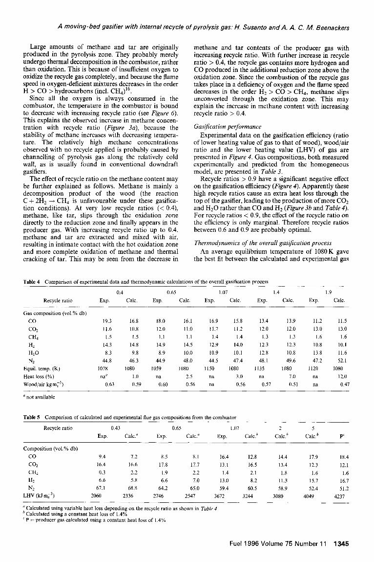
Results of the thermodynamic calculation of the overall gasification process are presented in Table 4. A compar- ison of calculated and measured flue gas compositions leaving the combustor is shown in Table 5. Calculated char consumptions in the countercurrent reduction zone based on the thermodynamic model are included in Figure 8.
Tar content Table 3 clearly shows a great reduction in tar content
of the producer gas through recycling of the pyrolysis gas to the air feed (compare experiments 1 and 2). This proved the positive effect of mixing tar with air prior to combustion. A further reduction of the tar content was obtained by the application of a separate combustor as shown in experiments 3 and 4.
1200
d 800 S ;;; & 600
E” g 400
a ‘-,*--.*,, _--11-w.” &.:~:&-.A--_A:t$, 4 R=0.4
25” A4-a. . R=l.O p-& A R=1.4
\. .L. ‘.\ . .
‘* ‘: *\ ‘.,
‘+
Combo&r outlet
I I
Top of bed
01 I I I I I I I I 0 0.5 0.5 0.5 0.5 0.5 0.5
Distance from bottom of bed, m
Figure 5 Temperature profiles in the gasifier for three recycle ratios. Distance is from the bottom of the bed (grate)
- Combustor (model) ??Combustor (exp) . Highest bed temperature
Bottom of bed
??* --*- 0. . ??-4.W
.-.O_ A-A-A . .A-
Recycle ratio
Figure 6 Temperature in combustor, highest bed temperature and temperature at bottom of gasifier as a function of recycle ratio. Data for no recycle taken from conventional co-current gasifier
The recycle ratio appeared to have only a minor influence on the tar content in the producer gas as long as a stable flame could be maintained in the combustor (see Figure 3a). Complete decomposition of tar can be expected at a temperature of N 1400K. Over charcoal this already occurs at a temperature of - 1125 K9. The residual tar in the producer gas, < 0.1 gmi3 as measured in these experiments, is possibly a stable end-product of the decomposition3’4. If so, this implies that it cannot be reduced any further.
According to the mass balance, a minimum recycle ratio of N 0.4 is necessary to withdraw all pyrolysis gas, provided that plug flow of the gas exists in the pyrolysis zone. However, some gas channelling and deviation from plug flow are unavoidable in such a bed of irregular particles15 . This causes only part of the pyrolysis gas to be effectively sucked into the recycle system, whereas another part slips down into the reduction zone, resulting in still high methane and tar contents in the producer gas at this low recycle ratio of - 0.4. However, a recycle ratio > 0.6 proves to be sufficient to extract all the pyrolysis gas (see Figure 3a).
Top of bed
0 I I I I I I 0 0.1 0.2 0.3 0.4 0.5 0.6
Depth from the top of bed, m
Figure 7 Solids conversion profiles in the pyrolysis zone. Solids conversion = (Si, - S)/(&, - Sr), where Sin = initial solid mass, wood (db), Sr = final solid mass at complete pyrolysis, 29% of Sr,, (from experiments in thermobalance) and S = solid mass at any position. Depth of bed = 0 at top of bed and 0.6m at the outlet of the combustor
loo
90 ??Experiment - Model
80 @ c 70
60 -
50 -
40-
30 -
20 -
IO -
n ??0 0.5 I 1.5 2 2.5 3
Recycle ratio
Figure 8 Char consumed in the countercurrent reduction zone. Model was calculated using a fixed heat loss of 1.4%. Char
consumDtion = (mc,c/mc,,,h) - hl~c/mcl,ash) 1oo%
Pwk,ash) where mc,c = carbon content of stream m,, char produced from pyrolysis (see Figure I), llz,,,,k = ash content of stream m,, char produced from pyrolysis, rn+ = carbon content of stream, m,t,& = ash content of stream m,,, char leaving countercurrent reduction zone
1344 Fuel 1996 Volume 75 Number 11
A moving-bed gasifier with internal recycle of pyrolysis gas: H. Susanto and A. A. C. M. Beenackers
Large amounts of methane and tar are originally produced in the pyrolysis zone. They probably merely undergo thermal decomposition in the combustor, rather than oxidation. This is because of insufficient oxygen to oxidize the recycle gas completely, and because the flame speed in oxygen-deficient mixtures decreases in the order H > CO > hydrocarbons (incl. CHq)16.
Since all the oxygen is always consumed in the combustor, the temperature in the combustor is bound to decrease with increasing recycle ratio (see Figure 6). This explains the observed increase in methane concen- tration with recycle ratio (Figure 3a), because the stability of methane increases with decreasing tempera- ture. The relatively high methane concentrations observed with no recycle applied is probably caused by channelling of pyrolysis gas along the relatively cold wall, as is usually found in conventional downdraft gasifiers.
The effect of recycle ratio on the methane content may be further explained as follows. Methane is mainly a decomposition product of the wood (the reaction C + 2H2 + CH4 is unfavourable under these gasifica- tion conditions). At very low recycle ratios (< 0.4), methane, like tar, slips through the oxidation zone directly to the reduction zone and finally appears in the producer gas. With increasing recycle ratio up to 0.4, methane and tar are extracted and mixed with air, resulting in intimate contact with the hot oxidation zone and more complete oxidation of methane and thermal cracking of tar. This may be seen from the decrease in
methane and tar contents of the producer gas with increasing recycle ratio. With further increase in recycle ratio > 0.4, the recycle gas contains more hydrogen and CO produced in the additional reduction zone above the oxidation zone. Since the combustion of the recycle gas takes place in a deficiency of oxygen and the flame speed decreases in the order H2 > CO > CH4, methane slips unconverted through the oxidation zone. This may explain the increase in methane content with increasing recycle ratio > 0.4.
Gasljication performance Experimental data on the gasification efficiency (ratio
of lower heating value of gas to that of wood), wood/air ratio and the lower heating value (LHV) of gas are presented in Figure 4. Gas compositions, both measured experimentally and predicted from the homogeneous model, are presented in Table 3.
Recycle ratios > 0.9 have a significant negative effect on the gasification efficiency (Figure 4). Apparently these high recycle ratios cause an extra heat loss through the top of the gasifier, leading to the production of more CO2 and H20 rather than CO and H2 (Figure 3b and Table 4). For recycle ratios < 0.9, the effect of the recycle ratio on the efficiency is only marginal. Therefore recycle ratios between 0.6 and 0.9 are probably optimal.
Thermodynamics of the overall ga$cation process An average equilibrium temperature of 1080K gave
the best fit between the calculated and experimental gas
Table 4 Comparison of experimental data and thermodynamic calculations of the overall gasification process
Recycle ratio
Gas composition (vol.% db) co co2
CH4
H2
H20
N2
Equil. temp. (K)
Heat loss (%) Wood/air kg mL3)
‘not available
0.4 0.65 1.07 1.4 1.9
Exp. Calc. Exp. Calc. Exp. Calc. Exp. Calc. Exp. Calc.
19.3 16.8 18.0 16.1 16.9 15.8 13.4 13.9 11.2 11.5 11.6 10.8 12.0 11.0 11.7 11.2 12.0 12.0 13.0 13.0 1.5 1.5 1.1 1.1 1.4 1.4 1.3 1.3 1.6 1.6
14.3 14.8 14.9 14.5 12.9 14.0 12.3 12.3 10.8 10.1 8.3 9.8 8.9 10.0 10.9 10.1 12.8 10.8 13.8 11.6
44.8 46.3 44.9 48.0 44.5 47.4 48.1 49.6 47.2 52.1 1078 1080 1059 1080 1150 1080 1135 1080 1120 1080
nay 1.0 na 2.5 na 3.0 na 7.0 na 12.0 0.63 0.59 0.60 0.56 na 0.56 0.57 0.51 na 0.47
Table 5 Comparison of calculated and experimental flue gas compositions from the combustor
Recycle ratio 0.43 0.65 1.07 2 5 Exp. Calc.” Exp. Calc.” Exp. Calc.’ Caleb Caleb PC
Composition (vol.% db)
co
(32
CH4
H? N2
LHV (W rn13)
9.4 7.2 8.5 8.1 16.4 12.8 14.4 17.9 18.4
16.4 16.6 17.8 11.7 13.1 16.5 13.4 12.3 12.1 0.3 2.2 1.9 2.2 1.4 2.1 1.8 1.6 1.6 6.6 5.8 6.6 7.0 13.0 8.2 11.3 15.7 16.7
67.1 68.8 64.2 65.0 59.4 60.5 58.9 52.4 51.2 2060 2336 2746 2547 3672 3244 3080 4049 4237
’ Calculated using variable heat loss depending on the recycle ratio as shown in Table 4 b Calculated using a constant heat loss of 1.4% ‘ P = producer gas calculated using a constant heat loss of 1.4%
Fuel 1996 Volume 75 Number 11 1345

A moving-bed gasifier with internal recycle of pyrolysis gas: H. Susanto and A. A. C. IV. Beenackers
compositions (Table 4). This value accords with the values of 1123 K and 1053 K reported for wood gasification2 and coal gasification13 respectively. From the experimental data (see Figure 5), it follows that the homogeneous water-gas shift reaction is frozen near the bottom of the char bed.
The calculations on the overall gasification process confirm that the heat loss increases with increasing recycle ratio, particularly at a recycle ratio of > 1 (Table 4). The increase in heat loss with increasing recycle ratio was confirmed experimentally from measurements of the wall temperature. Of course, improving the insulation, especially in the upper part of the gasifier, will minimize the extra heat loss and thus improve the gasification performance.
Temperatures in the gasljier The recycle ratio influenced the bed temperature
profile, especially in the upper part of the gasifier (Figure 5). At a recycle ratio of - 1.4, the temperature at the top of the bed attained 723K, which is the pyrolysis final temperature as reported in the literature17. Therefore the pyrolysis process is probably already complete at the top of the bed at recycle ratios of > 1.4 (Figure 7).
As expected and discussed above, the use of a separate combustor substantially lowered the highest bed temperature (see Figure 6). The highest bed tempera- tures are less affected by the actual value of the recycle ratio, which can be understood from the fact that the net heat input to the process is independent of the recycle ratio.
The thermodynamic model correctly predicts the trend of the combustor temperatures as a function of the recycle ratio, although the calculated results are system- atically 300-400K higher than the measured data. The discrepancy is probably due to the simplifying model assumption of no heat extraction from the combustor.
As the highest bed temperature is reduced by 200 K due to the recycle, this system offers a prospective opportunity for handling biomass having a low-melting ash. Some preliminary experiments with rice husk showed indeed no ash melting, and a good quality of gas was obtained.
Combustor j&e gas The composition and heating value of the flue gas
(leaving the combustor) are of course affected by the recycle ratio. An increase in the heating value with increasing recycle ratio was found both theoretically and experimentally (Table 5). At an infinite recycle ratio, the heating value of the flue gas would be identical to that of the producer gas.
Pyrolysis zone Figure 7 shows the experimentally measured profiles of
the solids conversion in the pyrolysis zone for recycle ratios of 0.4, 1.0 and 1.4. Smooth solids conversion profiles were found, which is understandable because the pyrolysis proceeds at a relatively slow heating rate17. Complete pyrolysis was always observed at the end of the pyrolysis zone. At a low recycle ratio, the heat of conduction from the combustor must have a pronounced effect on the pyrolysis process.
At recycle ratios of 1 .O and 1.4, the actual solids conversions at the top of the bed were found to be - 30
1346 Fuel 1996 Volume 75 Number 11
and N 50% respectively (Figure 7). Therefore complete pyrolysis at these recycle ratios is already established at N 0.4 and N 0.2m from the top of the bed. This clearly indicates the enhancing effect of the recycle on the pyrolysis process. Hence the char in the bed between the pyrolysis zone and the combustor outlet may undergo reduction reactions. If so, a countercurrent reduction zone exists at high recycle ratios.
Countercurrent reduction zone At recycle ratios < 0.4, the updraft blast flow rate is
too low for a countercurrent reduction zone to exist. At recycle ratios > 0.4, the extent of the countercurrent reduction zone appears to increase with increasing recycle ratio (Figure 8).
The calculated char consumptions are in good agreement with the experimental data (see Figure 8). The thermodynamic simulation further showed the char consumption to approach 100% asymptotically at higher recycle ratios. Thus at extremely high recycle ratios the location of the reduction zone might shift completely above the combustor outlet.
CONCLUSIONS
A moving-bed gasifier with an internal recycle and separate combustion of pyrolysis gas offers excellent opportunities for solving the problems met in scaling-up the conventional co-current downdraft gasifier. The recycle system greatly reduces the tar content of the producer gas, to < 0.1 gmL3. The tar content decreases with increasing recycle ratio to N 0.6 (ratio of recycle gas to gasifying air, v/v at s.t.p.). At recycle ratios > 0.6, no further tar reduction was observed.
Particularly at recycle ratios > 0.9, the gasification efficiency decreased with increasing recycle ratio. How- ever, improving the thermal insulation may reduce this effect substantially.
With a pyrolysis bed of 0.6m, complete pyrolysis of wood was observed experimentally already at depths of 0.3 and 0.2 m below the top of the bed at recycle ratios of 1.0 and 1.4 respectively. The increase in the solids conversion with increasing recycle ratio could also be explained by thermodynamic analysis of this modified gasifier.
The use of a separate combustor lowers the highest temperature of the bed to 973 K, compared with 1273 K in a conventional co-current moving-bed gasifier. The observed effect of the recycle ratio on the decrease of the highest bed temperature was qualitatively in agreement with the thermodynamic analysis.
A recycle ratio in the range 0.6-0.9 appears to be optimal with respect to clean gas production and good gasification efficiency. The system also seems particularly effective for gasifying biomass having a low ash melting point such as rice husk and municipal waste-derived fuel.
ACKNOWLEDGEMENTS
The financial support of the Netherlands Ministry of Development Cooperation, The Hague, is greatly acknowledged. The authors also acknowledge the technical facilities offered by Twente University, Enschede, where most of the experiments were carried out.

A moving-bed gasifier with internal recycle of pyrolysis gas: H. Susanto and A. A. C. M. Beenackers
REFERENCES
Osterreichisches Kuratorium fur Wirtschaftlichkeit. ‘Holzgas- Generatoren’, Springer-Verlag, 1937 Hos, J. J., Groeneveld, M. J. and van Swaaij, W. P. M. In Proceedings of the IGT Symposium on Energy from Biomass and Wastes IV, 1980, pp. 333-351 Kurkela, E. and Stahlberg, P. Fuel Process. Technol. 1992,31, 1 Pedersen, K. In ‘Advances in Thermochemical Biomass Conversion’, 1994, pp. 246-264 Czemik, S., Koeberle, P. G., Jollez, P., Bilodeau, F. L. and Chomet, E. In ‘Advances in Thermochemical Biomass Conversion’. 1994, pp. 423-437 Balbio, R. and G-Bacaicoa, P. In ‘Advances in Thermochemical Biomass Conversion’, 1994, pp. 350-364 Groeneveld, M. J. ‘The Co-current Moving Bed Gasifier’, Ph.D. Thesis, Twente University, 1980
10
11
12
13 14 15 16 17
Wang, Y. and Kinoshita, C. M. In ‘Advances in Thermochemi- cal Biomass Conversion’, 1994, pp. 280-287 Chembukulam, S. K., Dandge, A. S., Kovilur, N. L., Seshagiri, R. K. and Valdyeswaran, R. Ind. Eng. Chem. Prod. Res. Dev. 1981,20, 714 Johannesen, N. H. ‘Ejector Theory and Experiments’, Trans. Danish Acad. Tech. Sci. 1951, (1) Perry, R. H. and Chilton, C. H. (Eds). ‘Chemical Engineer’s Handbook, 5th Edn, McGraw-Hill, New York, 1973 Fristom, R. M. and Westerberg, A. A. ‘Flame Structure’, McGraw-Hill, New York, 1965, Ch. V Woodmansee, D. E. Energy Commun. 1976,2, 13. Yoon, H., Wei, J. and Denn, M. M. AIChE b.. 1978,24, 885 Schlunder, E. U. Chem. Eng. Ski. 1977,32, 845 Gibb, G. J. and Calcote, H. F. J. Chem. Eng. Data 1959,4,226 Kanury, A. M. Combust. Flame 1971. 18, 75
Fuel 1996 Volume 75 Number 11 1347