A MODIFIED PROCEDURE TO EVALUATE ACTIVE EARTH …
8
SPECIAL ISSUE OF SOILS AND FOUNDATIONS 209-216, Sept. 199845 Japanese Geotechnical Society A MODIFIED PROCEDURE TO EVALUATE ACTIVE EARTH PRESSURE AT HIGH SEISMIC LOADS JUNICHI KOSEKID, FUMIO TATSUOKAiD, YULMAN MUNAFilD, MASARU TATEYAMAiv) and KENICHI KOJIMAv) ABSTRACT A modified and pseudo-static limit-equilibrium approach to evaluate active earth pressure at high seismic load levels is proposed. Although it is similar to the Mononobe-Okabe method, the proposed method considers the effects of strain localization in the backfill soil and associated post-peak reduction in the shear resistance from peak to residual values along a previously formed failure plane. The proposed method can reflect differences in the peak shear resistance of the backfill soil with different degrees of compaction; yields a realistic active earth pressure coefficient which is smaller than that predicted by the Mononobe-Okabe method using a residual shear resistance; can be adapted to analyses with a large horizontal seismic coefficient where the Mononobe-Okabe method using the residual shear resistance is not applicable; and renders a reduced and more realistic size of active failure zone in the backfill soil at high seismic load levels compared to that predicted by the Mononobe-Okabe method. Key words: active earth pressure, earthquake, (failure plane), (limit equilibrium method), residual strength, retaining wall, sand, (strain localization) (IGC: E5/E8) INTRODUCTION The well-known Mononobe-Okabe method, based on a pseudo-static and limit-equilibrium approach, was proposed to calculate the seismic earth pressure (Okabe, 1924; Mononobe and Matsuo, 1929). Since then, a varie- ty of shaking model tests have been conducted to study on the seismic earth pressure. For example, Ohara et al. (1970) showed that the total active earth pressure meas- ured in their sinusoidally shaken model tests was consis- tent with the value calculated by the Mononobe-Okabe method when the shear resistance angle of the backfill soil was assumed to decrease as the shaking acceleration increased. They also showed that the vertical distribution of the measured active earth pressure was not hydrostatic but dependent on the displacement mode of the model wall. Other similar investigations include those by Ichihara and Matsuzawa (1973) and Ishibashi and Fang (1987). It was suggested by these previous investigations that, in general, the Mononobe-Okabe method can reasonably predict the total active earth pressure during earthquake, although its point of application is located higher than that derived from the assumption of hydrostatic distribution, which may lead to an underesti- mation of overturning moment of the wall due to the earth pressure. It is to be noted that seismic loads exam- ined in the experimental studies were limited to relatively low levels; the amplitude of input acceleration was smaller than 500 cm/ sec2. For retaining walls with relatively less importance, aseismic design is usually omitted by assuming that a wall that is designed against static loads has a safety margin and the margin would cover the additional resistance re- quired against seismic loads (e.g., JRA, 1987). In many of the design specifications or guidelines in Japan for rela- tively important retaining walls, the Mononobe-Okabe method has been adopted together with the assumption of hydrostatic distribution to evaluate the seismic active earth pressure. Alternatively, the trial wedge method, which is in principle equivalent to the Mononobe-Okabe method when the surface of the backfill soil is flat, has been employed for backfill soil having an irregular cross- section. In these aseismic design procedures, relatively small values are assigned for the shear resistance angle of i) Associate Professor, Institute of Industrial Science, University of Tokyo, Roppongi 7-22-1, Minato-ku, Tokyo 106-8558. ii) Professor, Department of Civil Engineering, University of Tokyo, Hongo 7-3-1, Bunkyo-ku, Tokyo 113-8656. iii) Graduate Student, Institute of Industrial Science, University of Tokyo, Roppongi 7-22-1, Minato-ku, Tokyo 106-8558. iv) Chief Engineer, Railway Technical Research Institute, Hikari-machi 2-8-38, Kokubunji city, Tokyo 185-8540. v) Engineer, Railway Technical Research Institute, ditto. Manuscript was received for review on August 25, 1997. Written discussions on this paper should be submitted before April 1, 1999 to the Japanese Geotechnical Society, Sugayama Bldg., 4F, Kan- da Awaji-cho, 2-23, Chiyoda-ku Tokyo 101-0063, Japan. Upon request the closing date may be extended one month. 209
Transcript of A MODIFIED PROCEDURE TO EVALUATE ACTIVE EARTH …

SPECIAL ISSUE OF SOILS AND FOUNDATIONS 209-216, Sept. 199845
Japanese Geotechnical Society
A MODIFIED PROCEDURE TO EVALUATE ACTIVE EARTH
PRESSURE AT HIGH SEISMIC LOADS
JUNICHI KOSEKID, FUMIO TATSUOKAiD, YULMAN MUNAFilD,
MASARU TATEYAMAiv) and KENICHI KOJIMAv)
ABSTRACT
A modified and pseudo-static limit-equilibrium approach to evaluate active earth pressure at high seismic load levels is proposed. Although it is similar to the Mononobe-Okabe method, the proposed method considers the effects of strain localization in the backfill soil and associated post-peak reduction in the shear resistance from peak to residual values along a previously formed failure plane. The proposed method can reflect differences in the peak shear resistance of the backfill soil with different degrees of compaction; yields a realistic active earth pressure coefficient which is smaller than that predicted by the Mononobe-Okabe method using a residual shear resistance; can be adapted to analyses with a large horizontal seismic coefficient where the Mononobe-Okabe method using the residual shear resistance is not applicable; and renders a reduced and more realistic size of active failure zone in the backfill soil at high seismic load levels compared to that predicted by the Mononobe-Okabe method.
Key words: active earth pressure, earthquake, (failure plane), (limit equilibrium method), residual strength, retaining wall, sand, (strain localization) (IGC: E5/E8)
INTRODUCTION
The well-known Mononobe-Okabe method, based on a pseudo-static and limit-equilibrium approach, was proposed to calculate the seismic earth pressure (Okabe, 1924; Mononobe and Matsuo, 1929). Since then, a varie-ty of shaking model tests have been conducted to study on the seismic earth pressure. For example, Ohara et al.
(1970) showed that the total active earth pressure meas-ured in their sinusoidally shaken model tests was consis-tent with the value calculated by the Mononobe-Okabe method when the shear resistance angle of the backfill soil was assumed to decrease as the shaking acceleration increased. They also showed that the vertical distribution of the measured active earth pressure was not hydrostatic but dependent on the displacement mode of the model wall. Other similar investigations include those by Ichihara and Matsuzawa (1973) and Ishibashi and Fang (1987). It was suggested by these previous investigations that, in general, the Mononobe-Okabe method can
reasonably predict the total active earth pressure during earthquake, although its point of application is located
higher than that derived from the assumption of hydrostatic distribution, which may lead to an underesti-mation of overturning moment of the wall due to the earth pressure. It is to be noted that seismic loads exam-ined in the experimental studies were limited to relatively low levels; the amplitude of input acceleration was smaller than 500 cm/ sec2.
For retaining walls with relatively less importance, aseismic design is usually omitted by assuming that a wall that is designed against static loads has a safety margin and the margin would cover the additional resistance re-
quired against seismic loads (e.g., JRA, 1987). In many of the design specifications or guidelines in Japan for rela-tively important retaining walls, the Mononobe-Okabe method has been adopted together with the assumption of hydrostatic distribution to evaluate the seismic active earth pressure. Alternatively, the trial wedge method, which is in principle equivalent to the Mononobe-Okabe method when the surface of the backfill soil is flat, has been employed for backfill soil having an irregular cross-section. In these aseismic design procedures, relatively small values are assigned for the shear resistance angle of
i) Associate Professor, Institute of Industrial Science, University of Tokyo, Roppongi 7-22-1, Minato-ku, Tokyo 106-8558.
ii) Professor, Department of Civil Engineering, University of Tokyo, Hongo 7-3-1, Bunkyo-ku, Tokyo 113-8656.iii) Graduate Student, Institute of Industrial Science, University of Tokyo, Roppongi 7-22-1, Minato-ku, Tokyo 106-8558.iv) Chief Engineer, Railway Technical Research Institute, Hikari-machi 2-8-38, Kokubunji city, Tokyo 185-8540.v) Engineer, Railway Technical Research Institute, ditto.
Manuscript was received for review on August 25, 1997.
Written discussions on this paper should be submitted before April 1, 1999 to the Japanese Geotechnical Society, Sugayama Bldg., 4F, Kan-
da Awaji-cho, 2-23, Chiyoda-ku Tokyo 101-0063, Japan. Upon request the closing date may be extended one month.
209
210 KOSEKI ET AL.
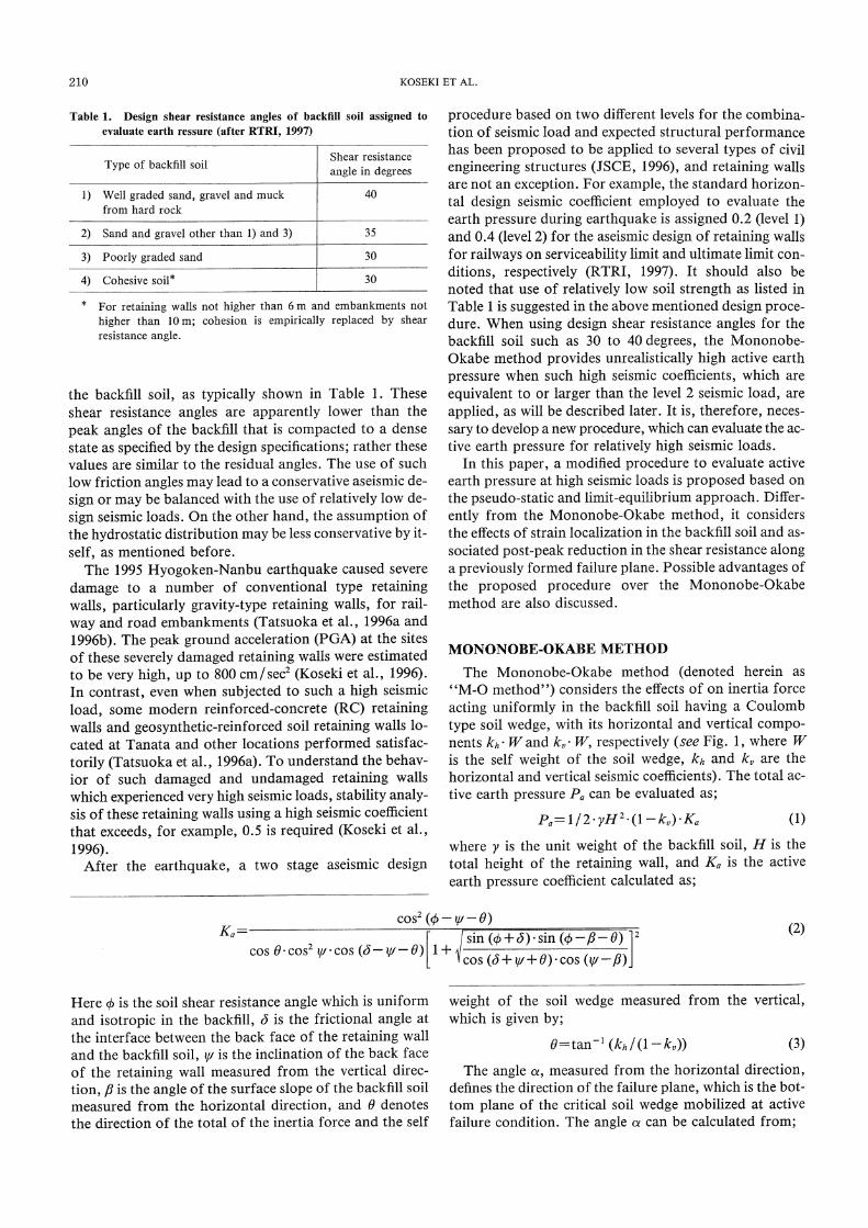
the backfill soil, as typically shown in Table 1. These shear resistance angles are apparently lower than the
peak angles of the backfill that is compacted to a dense state as specified by the design specifications; rather these values are similar to the residual angles. The use of such low friction angles may lead to a conservative aseismic de-sign or may be balanced with the use of relatively low de-sign seismic loads. On the other hand, the assumption of the hydrostatic distribution may be less conservative by it-self, as mentioned before.
The 1995 Hyogoken-Nanbu earthquake caused severe damage to a number of conventional type retaining walls, particularly gravity-type retaining walls, for rail-way and road embankments (Tatsuoka et al. , 1996a and 1996b). The peak ground acceleration (PGA) at the sites of these severely damaged retaining walls were estimated to be very high, up to 800 cm/ see (Koseki et al., 1996). In contrast, even when subjected to such a high seismic load, some modern reinforced-concrete (RC) retaining walls and geosynthetic-reinforced soil retaining walls lo-cated at Tanata and other locations performed satisfac-torily (Tatsuoka et al., 1996a). To understand the behav-ior of such damaged and undamaged retaining walls which experienced very high seismic loads, stability analy-sis of these retaining walls using a high seismic coefficient that exceeds, for example, 0.5 is required (Koseki et al., 1996).
After the earthquake, a two stage aseismic design
procedure based on two different levels for the combina-tion of seismic load and expected structural performance has been proposed to be applied to several types of civil engineering structures (JSCE, 1996), and retaining walls are not an exception. For example, the standard horizon-tal design seismic coefficient employed to evaluate the earth pressure during earthquake is assigned 0.2 (level 1) and 0.4 (level 2) for the aseismic design of retaining walls for railways on serviceability limit and ultimate limit con-ditions, respectively (RTRI, 1997). It should also be noted that use of relatively low soil strength as listed in Table 1 is suggested in the above mentioned design proce-dure. When using design shear resistance angles for the backfill soil such as 30 to 40 degrees, the Mononobe-Okabe method provides unrealistically high active earth
pressure when such high seismic coefficients, which are equivalent to or larger than the level 2 seismic load, are applied, as will be described later. It is, therefore, neces-sary to develop a new procedure, which can evaluate the ac-tive earth pressure for relatively high seismic loads.
In this paper, a modified procedure to evaluate active earth pressure at high seismic loads is proposed based on the pseudo-static and limit-equilibrium approach. Differ-ently from the Mononobe-Okabe method, it considers the effects of strain localization in the backfill soil and as-sociated post-peak reduction in the shear resistance along a previously formed failure plane. Possible advantages of the proposed procedure over the Mononobe-Okabe method are also discussed.
MONONOBE-OKABE METHOD
The Mononobe-Okabe method (denoted herein as "M -0 method") considers the effects of on inertia force
acting uniformly in the backfill soil having a Coulomb type soil wedge, with its horizontal and vertical compo-nents kh- W and kv- W, respectively (see Fig. 1, where W is the self weight of the soil wedge, kh and k, are the horizontal and vertical seismic coefficients). The total ac-tive earth pressure Pa can be evaluated as;
(1)
where y is the unit weight of the backfill soil, H is the
total height of the retaining wall, and Ka is the active
earth pressure coefficient calculated as;
(2)
Here ci) is the soil shear resistance angle which is uniform and isotropic in the backfill, 6 is the frictional angle at the interface between the back face of the retaining wall and the backfill soil, u is the inclination of the back face of the retaining wall measured from the vertical direc-tion, )8 is the angle of the surface slope of the backfill soil measured from the horizontal direction, and 0 denotes the direction of the total of the inertia force and the self
weight of the soil wedge measured from the vertical,
which is given by;
(3)
The angle a, measured from the horizontal direction,
defines the direction of the failure plane, which is the bot-tom plane of the critical soil wedge mobilized at active
failure condition. The angle a can be calculated from;
Table 1. Design shear resistance angles of backfill soil assigned to
evaluate earth ressure (after RTRI, 1997)

MODIFIED ACTIVE EARTH PRESSURE 211
(a)
(b)
(4)
Then the ratio of the failure zone length L in the backfill
soil, which is defined in Fig. 1, to the wall height H is
given by;
(5)
As an example, the active earth pressure coefficient Ka
and the ratio L/H are plotted versus the horizontal seis-
mic coefficient kh, respectively, in Figs. 2(a) and (b). For
this case, kv, yi, 13 and 5 are all zero and the value of q is
set equal to 30, 40 and 50 degrees. With a constant (/), the
value of Ka gradually increases with an increase in kh.
There are applicable upper limits of kh in the M-0
method as indicated by arrows in Fig. 2(a), beyond which
Ka cannot be evaluated where the term of "c/) ƒÓ-ƒÀ-0" in
the square-root term in Eq. (2) becomes negative. This
corresponds to a condition in which the pseudo-static
equilibrium of forces acting on the assumed soil wedge as
shown in Fig. 1 cannot be maintained, resulting in unsta-
ble behavior of the backfill soil, such as flow slide at its
surface.
As seen from Fig. 2(b), the ratio L/H also increases as
kh increases. The rate of increase in L/H is accelerated,
and the value of L/H becomes an unrealistically large
value when kh approaches and reaches the applicable
limit explained above.
EFFECTS OF STRAIN LOCALIZATION
In the M-0 method, the shear resistance of the backfill
soil is assumed to be uniform, isotropic and constant. It
has been shown, however, that the behavior of a soil
mass is affected by such factors as strength anisotropy,
progressive failure and strain localization. Among these,
effects of strain localization into a shear band (or a
failure plane) and associated strain-softening in the shear
band will be considered in the proposed procedure.
Effects of essential difference between the actual dynamic
behavior of the wall-soil system and its modeling based
on the pseudo-static and limit-equilibrium approach is be-
yond the scope of the present paper.
Yoshida et al. (1994) and Yoshida and Tatsuoka (1997)
conducted a series of plane strain compression tests on
dense sands and gravels to obtain the deformation prop-
erties of shear band. Figure 3 provides typical results
showing the relationships between the shear stress level
defined as R= {(ƒÐ1/ƒÐ3)-(ƒÐ1/ƒÐ3)res}/{(ƒÐ1/ƒÐ3)peak-(ƒÐ1/
0-3)res} and the normalized shear displacement increment
(us-(us)peak)/D5o which occurred across a shear band af-
ter the peak state. Here the subscripts "peak" and "res"
denote the peak and the residual states, respectively, and
us is the shear displacement across the shear band. These
results were obtained from plane strain compression tests
performed at cr3= 78 kPa, in which local deformation of
each specimen on the a2 plane was carefully observed to
obtain the value of us. It may be seen that a relative dis-
Fig. 1. Schematic diagram of forces acting on soil wedge assumed by
the Mononobe-Okabe method
Fig. 2. (a) Active earth pressure coefficient, (b) ratio of failure zone
length in backfill soil to wall height by the Mononobe-Okabe
method for 0=30•‹, 400, 50•‹ and 6=0•‹

212 KOSEKI ET AL.
placement in the direction parallel to the shear band
which is enough to reduce the mobilized shear resistance angle from the peak value to the residual value is rather
proportional to the particle size and about 5 to 10 times its mean diameter D50 (except for Isomi gravel). Based on results from dynamic centrifuge tests on retaining wall models, Bolton and Steedman (1985) also showed that
the shear resistance angle mobilized along a failure plane, which was formed in the backfill sand by shaking, dropped from 50 degrees to 33 degrees by a relative dis-
placement of the order of 10 times the mean particle di-ameter. These results indicate that in full-scale field cases, the drop of soil shear strength from the peak to residual values is very fast.
The amount of outward wall displacement to trigger the active failure of the backfill associated with the mobilization of the peak friction angle in the shear band
(or failure plane) is known to be very small; for a wallrotating about its base, the outward displacement at thewall top is about 0.1% of the wall height from the at restcondition (Terzaghi, 1920). For actual retaining walls, considering their finite bending stiffness and their rela-tively low resistance against external instability (sliding, overturning and loss of bearing capacity) compared to that against internal instability (physical damage to the wall body), it is likely that only slight deformation or dis-
placement of the wall is enough to trigger active failure in the backfill soil. Therefore, the active failure in the back-fill may occur at a seismic level which is far below the lev-el where the ultimate external failure of the wall takes
place. This would also be the case with very stiff and stati-cally very stable walls, although the difference between the seismic load level of the active failure in the backfill and the level of the ultimate external wall failure would be smaller. Note that the active failure in the backfill and the ultimate failure of a wall by, for example, complete overturning or unstable large outward sliding at the wall base, are different processes; in most cases, the latter type of failure occurs after the former type of failure has oc-
curred, as schematically shown in Fig. 4. The solid lines in this figure indicate the relationships between the out-ward displacement of the wall top 6 and the active earth
pressure at different seismic load levels, and the dashed line indicates the relationship between 6 and the wall resistance such as the friction at the wall base against the earth pressure. Intersection of these lines at a certain seis-mic load denotes an equilibrium point at that condition,
which moves from right to left in the figure when the seis-mic load increases, finally reaching the ultimate external wall failure condition. It should be noted that the post-
peak reduction of soil shear resistance in the shear band or along the failure plane, which has been formed by the
previous active failure (denoted as "initial active failure") prior to the ultimate external wall failure, may affect the consecutive mobilization of earth pressure at higher seismic loads, as illustrated below. The above-mentioned process is, in a broad sense, in accordance with the observation by Ohara et al. (1970) described in the INTRODUCTION.
As an example, the active earth pressure coefficient Ka
was calculated by changing the failure plane angle a
based on the equilibrium of forces acting on the soil
wedge as shown in Fig. 1. The results are plotted versus a
in Figs. 5(a) and (b), where kv, V, 16 and 6 are all set zero
for simplicity and (/) is assigned to be either 30 or 50
degrees as peak (ƒÓpeak) and residual (ƒÓres) values for typi-
cal dense sands. For each value of q5, kh is set at 0 and 0.4
in Fig. 5(a) and 0.62 and 0.8 in Fig. 5(b). The maximum values of Ka as indicated by solid horizontal arrows for cases of 0=50 degrees with kh = 0 to 0.8 are, in principle, equal to those obtained by the M-0 method with the same cl), although those values cannot be evaluated forφ=30 degrees with kh = 0.62 and 0.8, because these cases
are out of the applicable limit of the M-0 method, as
mentioned previously.
Here, an assumption that the initial active failure oc-
curs at kh=0 is employed. Then a failure plane (or a
shear band) should be formed at an angle of a =70
degrees, which in this case is equal to "45
degrees+(ƒÓpeak)/ 2" as derived from the Coulomb's ac-
tive earth pressure theory with zero values of kh, kv, Vr, ƒÀ
and 6. Along this failure plane, the shear resistance angle
Fig. 3. Relationship between shear stress level R= {(ƒÐ1/ƒÐ3)-(ƒÐ1/
σ3)res}/{(σ1/σ3)peak-(σ1/σ3)res} and normalized shear displace-
ment increment (us-(us)peak)/D50; ƒÐl and ƒÐ3 are the boundary
average major and minor principal stresses; si 4ƒÓpeak=
{(ƒÐ1/ƒÐ3)peak-1}/{(ƒÐ1/ƒÐ3)peak+1} and sin ƒÓres= {(ƒÐ1/ƒÐ3)res-1}/
{(σ1/σ3)res+1} (after Yoshida and Tatsuoka, 1997)
Fig. 4. Schematic relationship between displacement at wall top and
active earth pressure coefficient
MODIFIED ACTIVE EARTH PRESSURE 213
(a)
(b)
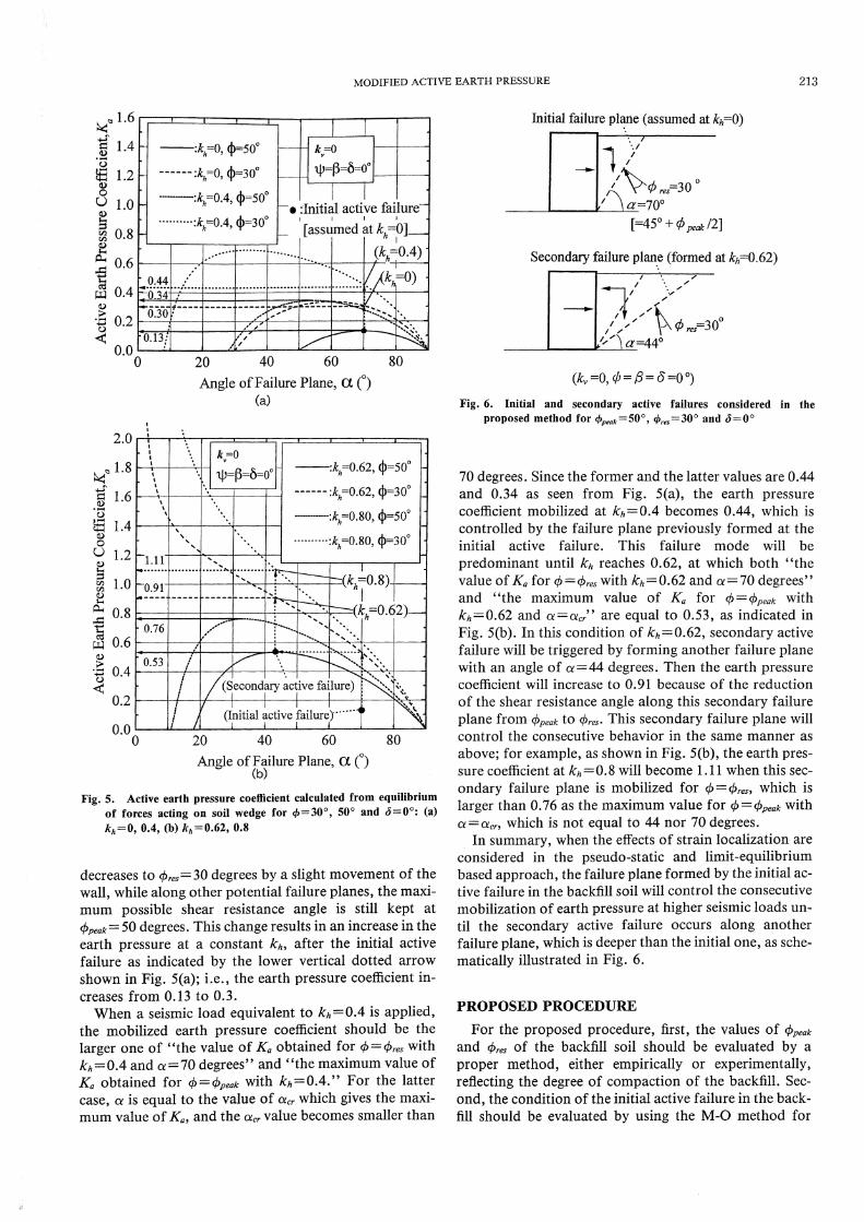
decreases to ƒÓres= 30 degrees by a slight movement of the
wall, while along other potential failure planes, the maxi-
mum possible shear resistance angle is still kept at
φpeak=50 degrees. This change results in an increase in the
earth pressure at a constant kh, after the initial active failure as indicated by the lower vertical dotted arrow shown in Fig. 5(a); i.e., the earth pressure coefficient in-creases from 0.13 to 0.3.
When a seismic load equivalent to kh = 0.4 is applied, the mobilized earth pressure coefficient should be the larger one of "the value of Ka obtained for 0= Ores with kh= 0.4 and a = 70 degrees" and "the maximum value of Ka obtained for = (Ppeak with kh 0.4." For the latter case, a is equal to the value of acr which gives the maxi-mum value of Ka, and the acr value becomes smaller than
70 degrees. Since the former and the latter values are 0.44
and 0.34 as seen from Fig. 5(a), the earth pressure
coefficient mobilized at kh= 0.4 becomes 0.44, which is
controlled by the failure plane previously formed at the
initial active failure. This failure mode will be
predominant until kh reaches 0.62, at which both "the
value of Ka for c/)= Ores with kh = 0.62 and a 70 degrees"
and "the maximum value of Ka for = 4ipeak with
kh= 0.62 and a =acr" are equal to 0.53, as indicated in
Fig. 5(b). In this condition of kh= 0.62, secondary active
failure will be triggered by forming another failure plane
with an angle of a=44 degrees. Then the earth pressure
coefficient will increase to 0.91 because of the reduction
of the shear resistance angle along this secondary failure
plane from ƒÓpeak to ƒÓres. This secondary failure plane will
control the consecutive behavior in the same manner as
above; for example, as shown in Fig. 5(b), the earth pres-
sure coefficient at kh=0.8 will become 1.11 when this sec-
ondary failure plane is mobilized for 0=0., which is
larger than 0.76 as the maximum value for ci)=Opeak with
α=αcr, which is not equal to 44 nor 70 degrees.
In summary, when the effects of strain localization are
considered in the pseudo-static and limit-equilibrium
based approach, the failure plane formed by the initial ac-
tive failure in the backfill soil will control the consecutive
mobilization of earth pressure at higher seismic loads un-
til the secondary active failure occurs along another
failure plane, which is deeper than the initial one, as sche-
matically illustrated in Fig. 6.
PROPOSED PROCEDURE
For the proposed procedure, first, the values of ƒÓ peak
and ƒÓres of the backfill soil should be evaluated by a
proper method, either empirically or experimentally,
reflecting the degree of compaction of the backfill. Sec-
ond, the condition of the initial active failure in the back-
fill should be evaluated by using the M-0 method for
Fig. 5. Active earth pressure coefficient calculated from equilibrium
of forces acting on soil wedge for 0=30•‹, 50•‹ and 6=0•‹: (a)
kh=0, 0.4, (b) kh=0.62, 0.8
Fig. 6. Initial and secondary active failures considered in the
proposed method for ƒÓpeak=50•‹, ƒÓres=30•‹ and ƒÐ=0•‹

214 KOSEKI ET AL.
φ=φpeak to obtain the angle a of the initial failure plane.
The relative stiffness of walls and their resistance against
external instability should be taken into account when
evaluating the initial active failure. Third, the active
earth pressure coefficient Ka mobilized by the initial
failure plane is calculated as;
(6)
where a reduced shear resistance angle ƒÓ equal to thic ,ƒÓres is
used, and the failure plane angle a is fixed to the critical
value acr for the initial active failure. This coefficient Ka is
compared with the one evaluated by the M-0 method,
with ƒÓ=ƒÓpeak. If the former value is smaller than the lat-
ter, the secondary active failure is judged to have already
occurred, for this the critical angle a, for the secondary
failure plane should be re-evaluated in order to calculate the coefficient Ka mobilized by this newer failure plane. Otherwise, the coefficient Ka calculated for the initial failure plane is considered to be still mobilized.
Values of Ka and L /H= cot a evaluated by the
proposed procedure based on the fixed failure plane an-gle (denoted as "F-P method") are plotted versus kh in
(a)
(b)
(a)
(b)
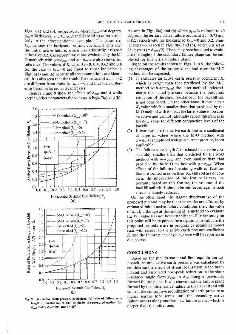
Fig. 7. (a) Active earth pressure coefficient, (b) ratio of failure zone
length in backfill soil to wall height by the proposed method for
φpeak=50°,φres=30°andδ=0°
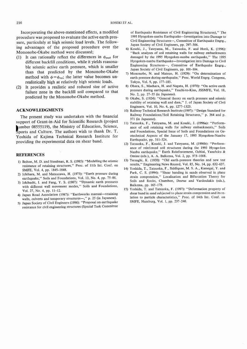
Fig. 8. (a) Active earth pressure coefficient, (b) ratio of failure zone
length in backfill soil to wall height by the proposed meihod for
φpeak=40°,φres=30°andδ=0°
MODIFIED ACTIVE EARTH PRESSURE 215
Figs. 7(a) and (b), respectively, where A ƒÓ peak= 50 degrees,
φres=30 degrees, and kv, v fl and (5 are all set at zero simi-larly to the aforementioned examples. The parameter
kh,cr denotes the horizontal seismic coefficient to trigger
the initial active failure, which was arbitrarily assigned
either 0 or 0.2. Corresponding values evaluated by the M-
O methods with ƒÓ=ƒÓpeak and ƒÓ=ƒÓres are also shown for
reference. The values of Ka when kh = 0, 0.4, 0.62 and 0.8
for the case of kh,,= 0 are equal to those indicated in
Figs. 5(a) and (b) because all the assumptions are identi-
cal. It is also seen that the results for the case of kh,,= 0.2
are different from those for kh,,= 0 and that their differ-
ence becomes larger as kh increases.
Figures 8 and 9 show the effects of ƒÓpeak and (3 while
keeping other parameters the same as in Figs. 7(a) and (b).
(a)
(b)
As seen in Figs. 8(a) and (b) whereƒÓpeak ireduced to 40
ƒÓ degrees, the tertiary active failure occurs at kh = 0.75 and
0.82, respectively, for the cases of kh,,= 0 and 0.2. Simi-
lar behavior is seen in Figs. 9(a) and (b), where is set at
25 degrees (=ƒÓpeak /2). The same procedure used to evalu-
ate the angle of the secondary failure plane can be em-
ployed for this tertiary failure plane.
Based on the results shown in Figs. 7 to 9, the follow-
ing advantages of the proposed method over the M-0
method can be expected;
(1) It evaluates an active earth pressure coefficient K.
which is larger than that predicted by the M-0
method with = Opeak; the latter method underesti-
mates the actual pressure because the post-peak
reduction of the shear resistance in the backfill soil
is not considered. On the other hand, it evaluates a
Ka value which is smaller than that predicted by the
M-0 method with 0=-0.; the latter value is too con-
servative and cannot rationally reflect differences in
the Opeak value for different compaction levels of the
backfill.
(2) It can evaluate the active earth pressure coefficient
at large kh values where the M-0 method with
φ=φres (as employed widely in current practice) is notapplicable.
(3) The failure zone length L is reduced so as to be con-
siderably smaller than that predicted by the M-0
method with ch th res, and even smaller than that
predicted by the M-0 method with ƒÓ=ƒÓpeak .When
effects of the failure of retaining walls on facilities
that are located in or on their backfill soil are of con-
cern, the implication of this feature is very im-
portant; based on this feature, the volume of the
backfill soil which should be reinforced against such
effects is largely reduced.
On the other hand, the largest disadvantage of the
proposed method may be that the results are affected by
estimated initial active failure conditions (i.e., the value
of kh,cr), although at this moment, a method to evaluate
the kh,, value has not been established. Further study on
this point will be required. Investigations to validate the
proposed procedure are in progress by means of model
tests with respect to the active earth pressure coefficient
Ka and the failure plane angle a, these will be reported in
due course.
CONCLUSIONS
Based on the pseudo-static and limit-equilibrium ap-
proach, seismic active earth pressure was calculated by
considering the effects of strain localization in the back-
fill soil and associated post-peak reduction in the shear
resistance angle from ƒÓpeak to ƒÓres along a previously
formed failure plane. It was shown that the failure plane
formed by the initial active failure in the backfill soil will
control the consecutive mobilization of earth pressure at
higher seismic load levels until the secondary active
failure occurs along another new failure plane, which is
deeper than the initial one.
Fig. 9. (a) Active earth pressure coefficient, (b) ratio of failure zone
length in backfill soil to wall height by the proposed method for
4peak=50•‹, 4res=30•‹ and 6=25•‹
216 KOSEKI ET AL.
Incorporating the above-mentioned effects, a modified
procedure was proposed to evaluate the active earth pres-sure, particulaly at high seismic load levels. The follow-ing advantages of the proposed procedure over the Mononobe-Okabe method were discussed;
(1) It can rationally reflect the differences in Cbpk for different backfill conditions, while it yields reasona-ble seismic active earth pressure, which is smaller
than that predicted by the Mononobe-Okabe method with 4 = Ores; the latter value becomes un-realistically high at relatively high seismic loads.
(2) It provides a realistic and reduced size of active failure zone in the backfill soil compared to that
predicted by the Mononobe-Okabe method.
ACKNOWLEDGMENTS
The present study was undertaken with the financial support of Grant-in-Aid for Scientific Research (project〓umber 08555119), the Ministry of Education, Science,Sports and Culture. The authors wish to thank Dr. T.
Yoshida of Kajima Technical Research Institute for
providing the experimental data on shear band.
REFERENCES
1) Bolton, M. D. and Steedman, R. S. (1985): "Modelling the seismic resistance of retaining structures," Proc. of 11th Int. Conf. on SMFE, Vol. 4, pp. 1845-1848.
2) Ichihara, M. and Matsuzawa, H. (1973): "Earth pressure during earthquake," Soils and Foundations, Vol. 13, No. 4, pp. 75-86.
3) Ishibashi, I. and Fang, Y. S. (1987): "Dynamic earth pressures with different wall movement modes," Soils and Foundations, Vol. 27, No. 4, pp. 11-12.
4) Japan Road Association (1987): "Earthworks manual-retaining walls, culverts and temporary structures-" p. 25 (in Japanese).
5) Japan Society of Civil Engineers (1996): "Proposal on earthquake resistance for civil engineering structures (Special Task Committee
of Earthquake Resistance of Civil Engineering Structures)," The 1995 Hyogoken-nanbu Earthquake-Investigation into Damage to Civil Engineering Structures- Committee of Earthquake Engrg., Japan Society of Civil Engineers, pp. 297-306.
6) Koseki, J., Tateyama, M., Tatsuoka, F. and Horii, K. (1996): "Back analyses of soil retaining walls for railway embankments
damaged by the 1995 Hyogoken-nanbu earthquake," The 1995 Hyogoken-nanbu Earthquake Investigation into Damage to Civil Engineering Structures-, Committee of Earthquake Engrg., Japan Society of Civil Engineers, pp. 101-104.
7) Mononobe, N. and Matsuo, H. (1929): "On determination of earth pressure during earthquake," Proc. World Engrg. Congress, Tokyo, Vol. 9, pp. 177-185.
8) Ohara, S., Maehara, H. and Nagata, H. (1970): "On active earth pressure during earthquake," Tsuchi-to-Kiso, JSSMFE, Vol. 18, No. 2, pp. 27-35 (in Japanese).
9) Okabe, S. (1924): "General theory on earth pressure and seismic stability of retaining wall and dam," J. of Japan Society of Civil Engineers, Vol. 10, No. 6, pp. 1277-1323.
10) Railway Technical Research Institute (1997): "Design Standard for Railway Foundations/Soil Retaining Structures," p. 364 and p. 371 (in Japanese).
11) Tatsuoka, F., Tateyama, M. and Koseki, J. (1996a): "Perform-ance of soil retaining walls for railway embankments," Soils and Foundations, Special Issue of Soils and Foundations on Ge-otechnical Aspects of the January 17, 1995 Hyogoken-Nambu Earthquake, pp. 311-324.
12) Tatsuoka, F., Koseki, J. and Tateyama, M. (1996b): "Perform-ance of reinforced soil structures during the 1995 Hyogo-ken Nanbu earthquake," Earth Reinforcement, Ochiai, Yasufuku & Omine (eds.), A. A. Balkema, Vol. 2, pp. 973-1008.
13) Terzaghi, K. (1920): "Old earth-pressure theories and new test results," Engineering News Record, Vol. 85, No. 14, pp. 632-637.
14) Yoshida, T., Tatsuoka, F., Siddiquee, M. S. A., Kamegai, Y. and Park, C. S. (1994): "Shear banding in sands observed in plane strain compression," Localisation and Bifurcation Theory for Soils and Rocks, Chambon, Desrue and Vardoulakis (eds.), Balkema, pp. 165-179.
15) Yoshida, T. and Tatsuoka, F. (1997): "Deformation property of shear band in sand subjected to plane strain compression and its re-lation to particle characteristics," Proc. of 14th Int. Conf. on SMFE, Hamburg, Vol. 1, pp. 237-240.