A Model-Based Systems Engineering (MBSE) Approach to the ...
39
11/18/20 Senior Principal RF Engineer John Hodge 1 A Model-Based Systems Engineering (MBSE) Approach to the Design & Optimization of Phased Array Antenna Systems Northrop Grumman Baltimore, MD Phoenix Integration Webinar Distribution Statement A: Approved for Public Release; Distribution is Unlimited; #20-2203 Dated 11/17/2020 © 2020 Northrop Grumman
Transcript of A Model-Based Systems Engineering (MBSE) Approach to the ...
11/18/20
Senior Principal RF Engineer
John Hodge
1
A Model-Based Systems Engineering (MBSE) Approach to the Design & Optimization of Phased Array Antenna Systems
Northrop Grumman
Baltimore, MD
Phoenix Integration Webinar
Distribution Statement A: Approved for Public Release; Distribution is Unlimited; #20-2203 Dated 11/17/2020 © 2020 Northrop Grumman

Northrop Grumman Today
2 Distribution Statement A: Approved for Public Release; Distribution is Unlimited; #20-2203 Dated 11/17/2020

3
Motivation
Challenge: Can we use a model-based Digital Engineering (DE)
approach to enhance phased array antenna design & development?
Increase Customer Satisfaction
Improve Stakeholder Communication
Increase Performance Capabilities
More Efficient System Architectures
Enhance Workflow Automation
Manage System Complexity
Reduce Cost & Schedule Inefficiencies
Distribution Statement A: Approved for Public Release; Distribution is Unlimited; #20-2203 Dated 11/17/2020
4
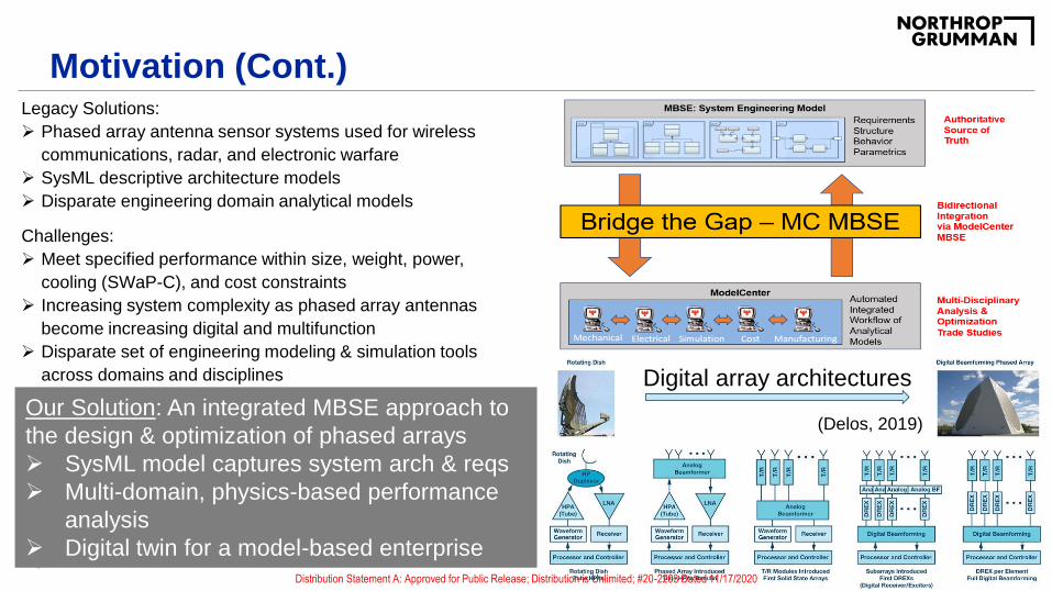
Motivation (Cont.)Legacy Solutions:
Phased array antenna sensor systems used for wireless
communications, radar, and electronic warfare
SysML descriptive architecture models
Disparate engineering domain analytical models
Challenges:
Meet specified performance within size, weight, power,
cooling (SWaP-C), and cost constraints
Increasing system complexity as phased array antennas
become increasing digital and multifunction
Disparate set of engineering modeling & simulation tools
across domains and disciplines
Our Solution: An integrated MBSE approach to
the design & optimization of phased arrays
SysML model captures system arch & reqs
Multi-domain, physics-based performance
analysis
Digital twin for a model-based enterprise
Digital array architectures
(Delos, 2019)
Distribution Statement A: Approved for Public Release; Distribution is Unlimited; #20-2203 Dated 11/17/2020
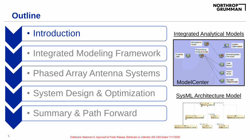
Outline
• Introduction
• Integrated Modeling Framework
• Phased Array Antenna Systems
• System Design & Optimization
• Summary & Path Forward
5
SysML Architecture Model
Integrated Analytical Models
ModelCenter
Distribution Statement A: Approved for Public Release; Distribution is Unlimited; #20-2203 Dated 11/17/2020
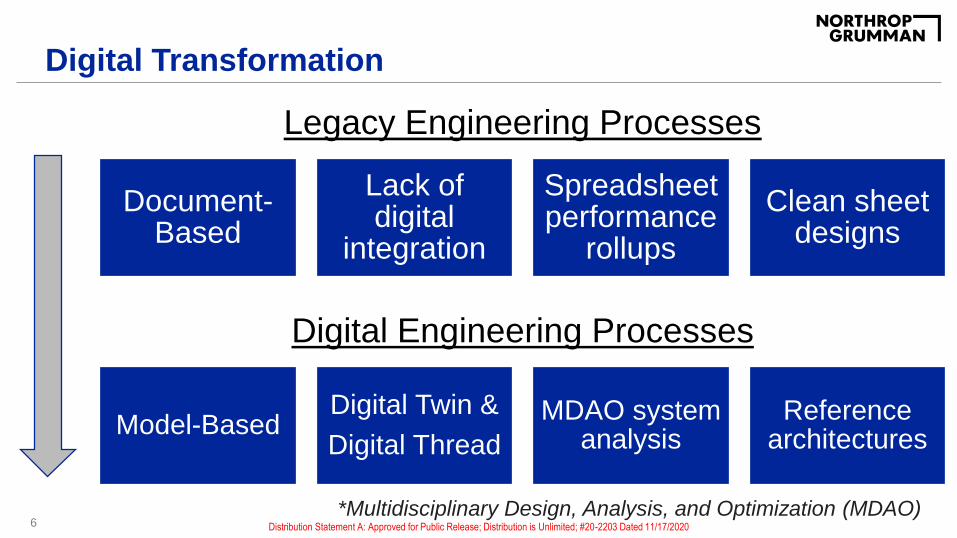
Digital Transformation
Document-Based
Lack of digital
integration
Spreadsheet performance
rollups
Clean sheet designs
6
Legacy Engineering Processes
Model-BasedDigital Twin &
Digital Thread
MDAO system analysis
Reference architectures
Digital Engineering Processes
*Multidisciplinary Design, Analysis, and Optimization (MDAO)Distribution Statement A: Approved for Public Release; Distribution is Unlimited; #20-2203 Dated 11/17/2020
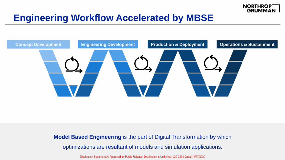
Engineering Workflow Accelerated by MBSE
7
Concept Development Engineering Development Production & Deployment Operations & Sustainment
Model Based Engineering is the part of Digital Transformation by which
optimizations are resultant of models and simulation applications.
Distribution Statement A: Approved for Public Release; Distribution is Unlimited; #20-2203 Dated 11/17/2020
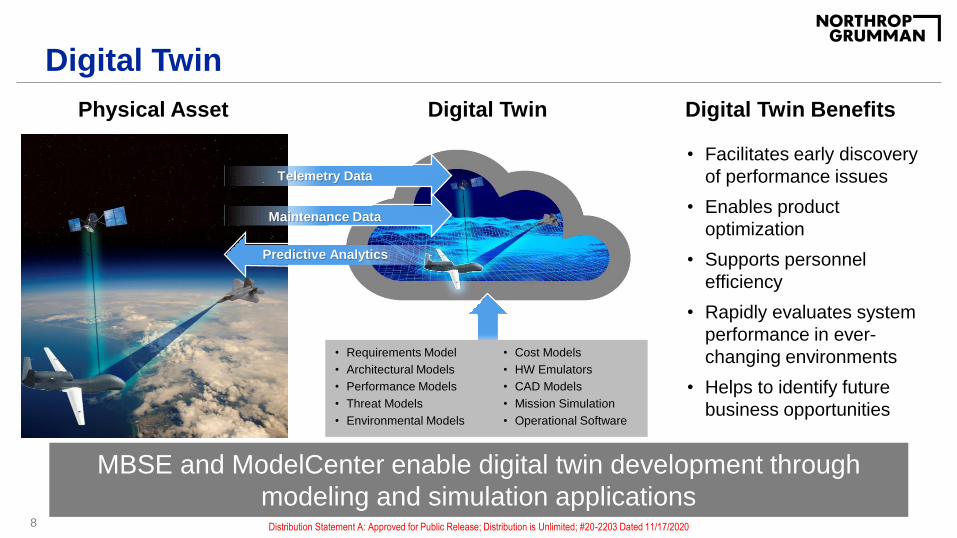
Digital Twin
8
Physical Asset Digital Twin
Predictive Analytics
Maintenance Data
Telemetry Data
• Requirements Model
• Architectural Models
• Performance Models
• Threat Models
• Environmental Models
• Cost Models
• HW Emulators
• CAD Models
• Mission Simulation
• Operational Software
Digital Twin Benefits
• Facilitates early discovery
of performance issues
• Enables product
optimization
• Supports personnel
efficiency
• Rapidly evaluates system
performance in ever-
changing environments
• Helps to identify future
business opportunities
MBSE and ModelCenter enable digital twin development through
modeling and simulation applicationsDistribution Statement A: Approved for Public Release; Distribution is Unlimited; #20-2203 Dated 11/17/2020
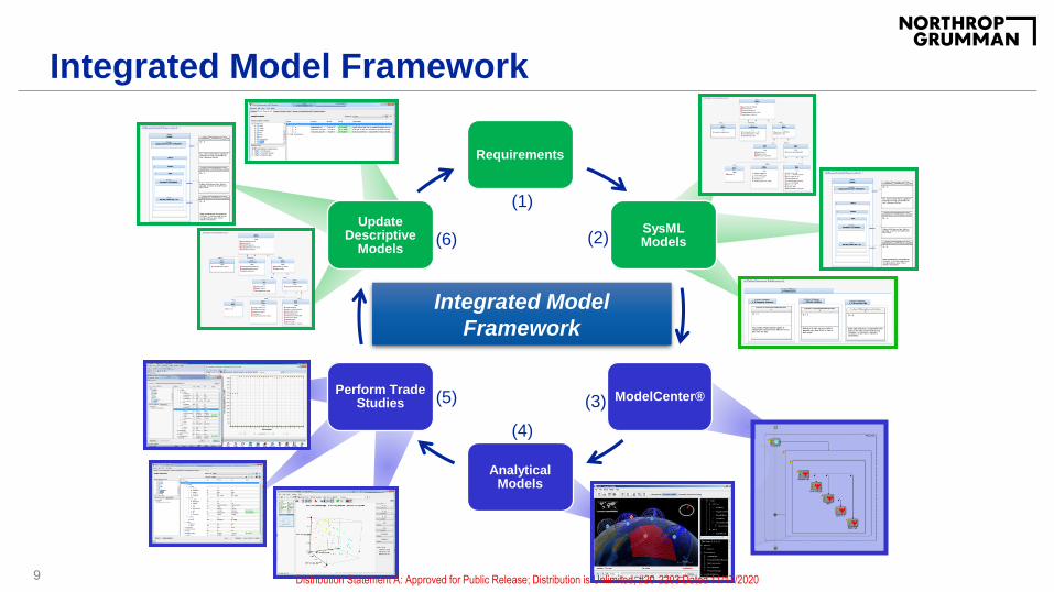
Integrated Model Framework
9
(1)
(2)
(3)
(4)
(5)
(6)
Integrated Model
Framework
Requirements
SysML Models
ModelCenter®
Analytical Models
Perform Trade Studies
Update Descriptive
Models
Distribution Statement A: Approved for Public Release; Distribution is Unlimited; #20-2203 Dated 11/17/2020
10
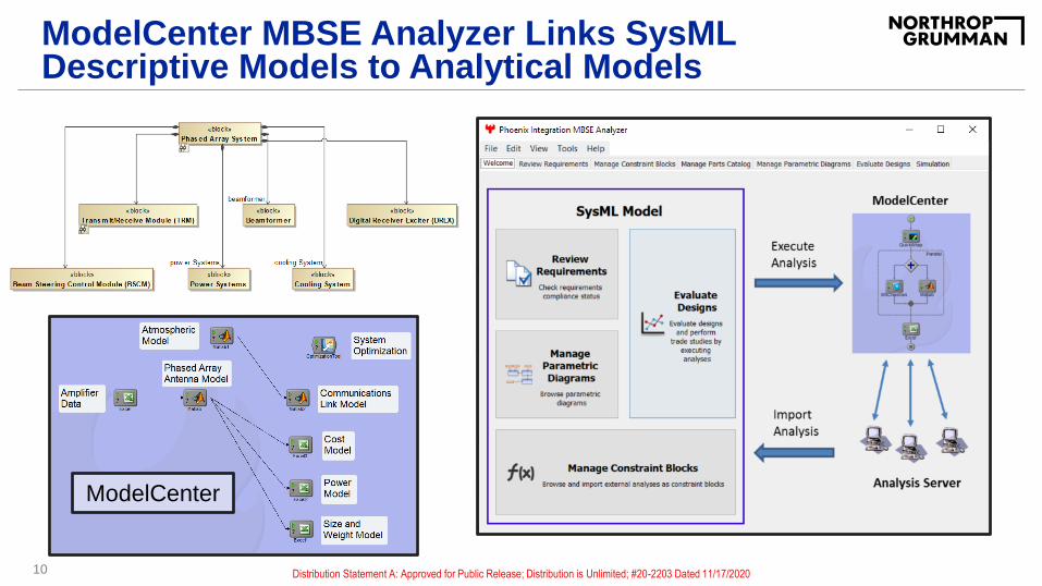
ModelCenter MBSE Analyzer Links SysML Descriptive Models to Analytical Models
ModelCenter
Distribution Statement A: Approved for Public Release; Distribution is Unlimited; #20-2203 Dated 11/17/2020

Phased Array Antenna Systems
11 Distribution Statement A: Approved for Public Release; Distribution is Unlimited; #20-2203 Dated 11/17/2020

Dynamic Array Beam Steering Achieved Via Controlling Phase At Each Radiating Site
12
Radiating
Sites
Module Phase
Shifters
Phase
Settings
Energy is in phase at an
angle off array normal
In phase energy
produces a main beam
Smaller lobes
produced elsewhere
2D Array Pattern
Simulated E-fields
Distribution Statement A: Approved for Public Release; Distribution is Unlimited; #20-2203 Dated 11/17/2020

Phased Array Antenna System Block Diagram
13
Complex system with many subsystem and component interactions
Each component
has a size, weight,
power, and cooling
(SWaP-C)
contribution
Distribution Statement A: Approved for Public Release; Distribution is Unlimited; #20-2203 Dated 11/17/2020

Scalable Digital AESA Architecture
14
RF Front-End Digital Front-End
Common RF
Conversion and
DBF
Frequency and
Mission Specific
RF Front-End
Common Back-End
Processing and
Control
Distribution Statement A: Approved for Public Release; Distribution is Unlimited; #20-2203 Dated 11/17/2020
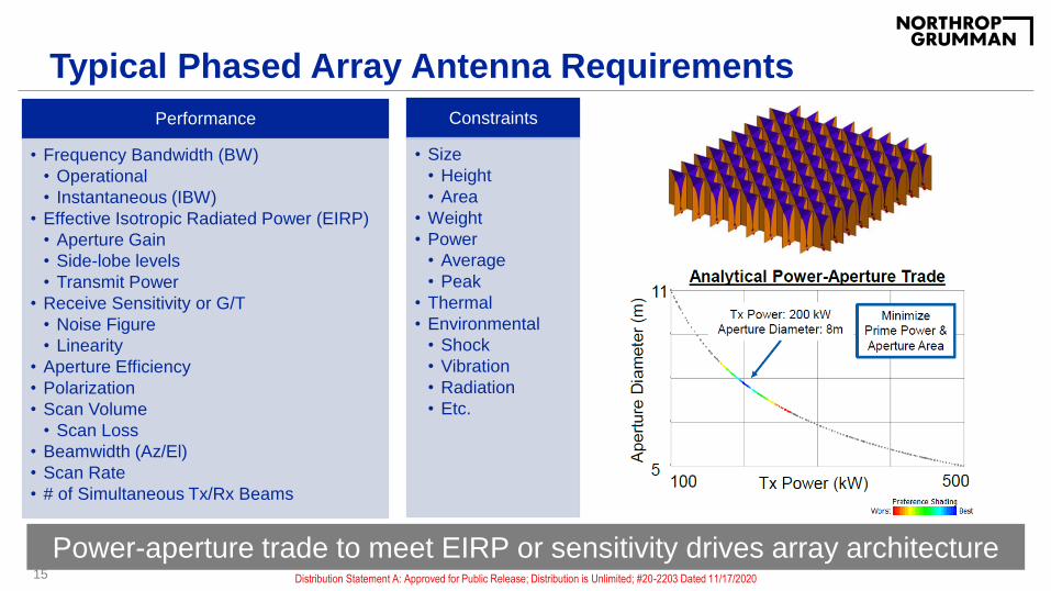
Typical Phased Array Antenna Requirements
15
Power-aperture trade to meet EIRP or sensitivity drives array architecture
Performance
• Frequency Bandwidth (BW)
• Operational
• Instantaneous (IBW)
• Effective Isotropic Radiated Power (EIRP)
• Aperture Gain
• Side-lobe levels
• Transmit Power
• Receive Sensitivity or G/T
• Noise Figure
• Linearity
• Aperture Efficiency
• Polarization
• Scan Volume
• Scan Loss
• Beamwidth (Az/El)
• Scan Rate
• # of Simultaneous Tx/Rx Beams
Constraints
• Size
• Height
• Area
• Weight
• Power
• Average
• Peak
• Thermal
• Environmental
• Shock
• Vibration
• Radiation
• Etc.
Distribution Statement A: Approved for Public Release; Distribution is Unlimited; #20-2203 Dated 11/17/2020

Capture Performance and SWaP-C Requirements in SysML
16
Requirements linked to provide traceability;
Verified using integrated analytical modelsDistribution Statement A: Approved for Public Release; Distribution is Unlimited; #20-2203 Dated 11/17/2020
*Hypothetical System

Requirements Drive RF Front-End Architecture
17
Frequency Bandwidth
Po
we
r H
an
dlin
g
Planar-Fed Folded Notch (PFFN)
Stepped Notch / VivaldiBAMAA Radiator:
Single Contiguous Conducting Piece-Part
TransformerSection
Feed
Balun Cavity
Translation LayerFunctionality Built-In
Additively Manufactured
(one single part)
Printed Connectors?
GxPOGxPO GxPOGxPO
Patch / Stacked Patch
Waveguide / Slot
PUMA [1]
TCDA [2]
[1] PUMA: Planar Ultrawideband Modular Array (Holland, 2012); [2] TCDA: Tight Coupled Dipole Array (Papantonis, 2016)
Scalable tile-based building blocks: Choose radiating element architecture
based on bandwidth, scan, power handling, and height requirements
Distribution Statement A: Approved for Public Release; Distribution is Unlimited; #20-2203 Dated 11/17/2020
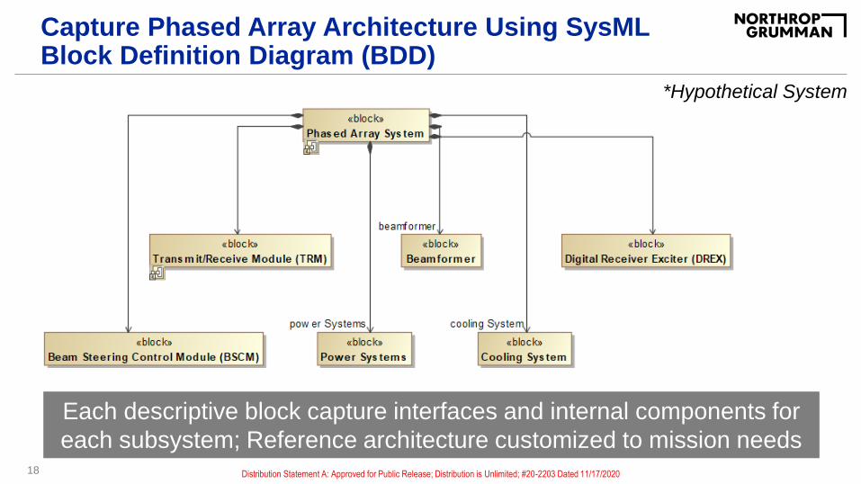
Capture Phased Array Architecture Using SysML Block Definition Diagram (BDD)
18
*Hypothetical System
Each descriptive block capture interfaces and internal components for
each subsystem; Reference architecture customized to mission needs
Distribution Statement A: Approved for Public Release; Distribution is Unlimited; #20-2203 Dated 11/17/2020

19
Increasing Levels of Fidelity Through the Antenna Design Process
HFSS, FEKO, CST
Matlab
Excel
SysML
Distribution Statement A: Approved for Public Release; Distribution is Unlimited; #20-2203 Dated 11/17/2020

Installed Array Performance Using FEKO EM Solver
20
Predict High-Fidelity Installed Antenna Radiation Patterns Using Full-
Wave EM Solver to Inform System Design Decisions
Surface
Currents
Installed Radiation
Pattern
Distribution Statement A: Approved for Public Release; Distribution is Unlimited; #20-2203 Dated 11/17/2020

System Design & Optimization
21 Distribution Statement A: Approved for Public Release; Distribution is Unlimited; #20-2203 Dated 11/17/2020

Use ModelCenter to Perform Parametric Performance vs. SWaP-C Trade Study Analysis
Inputs:
– Frequency
– Bandwidth
– Array Grid
– Amplifier Power Per Element
– Antenna Scan Angle
– # of Tx Beams
– Required SNR
22
Objective: Discover best system design and phased array architecture for a wireless communication system to achieve required signal-to-ratio (SNR) at receiver
Outputs:
– SNR at Receiver
– Link Margin
– Antenna EIRP
– Az/El Beamwidth
– Size
– Weight
– Prime Power
– Power Density
– Cost
ModelCenter
Distribution Statement A: Approved for Public Release; Distribution is Unlimited; #20-2203 Dated 11/17/2020
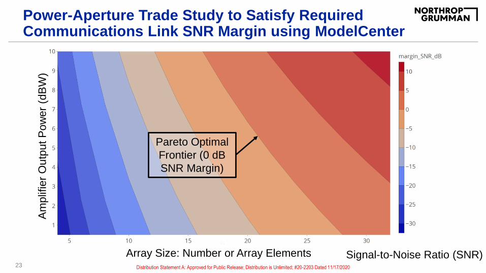
Power-Aperture Trade Study to Satisfy Required Communications Link SNR Margin using ModelCenter
23
Pareto Optimal
Frontier (0 dB
SNR Margin)
Array Size: Number or Array Elements
Am
plif
ier
Ou
tpu
t P
ow
er
(dB
W)
Signal-to-Noise Ratio (SNR)Distribution Statement A: Approved for Public Release; Distribution is Unlimited; #20-2203 Dated 11/17/2020

Understand how increasing array size drives EIRP, prime power, weight, and SNR link margin using ModelCenter
24
Model sensitivity of input design parameters on system KPPs and SWaP-C
Array Size: Number or Array Elements
Ke
y P
erf
orm
an
ce
Pa
ram
ete
rs
(KP
PS
)
Meets Required SNR
Distribution Statement A: Approved for Public Release; Distribution is Unlimited; #20-2203 Dated 11/17/2020
*Hypothetical System

Parametric trade study using design of experiment (DOE) tool simulates 630 system configurations
25
Each point is an evaluated system configuration; Gray dots shaded out
because they do not meet system requirements and constraintsDistribution Statement A: Approved for Public Release; Distribution is Unlimited; #20-2203 Dated 11/17/2020
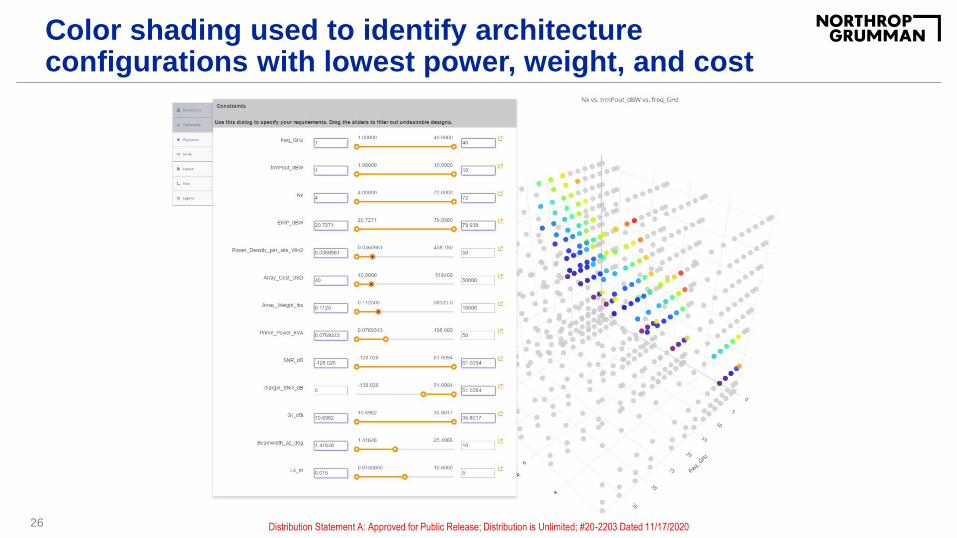
Color shading used to identify architecture configurations with lowest power, weight, and cost
26 Distribution Statement A: Approved for Public Release; Distribution is Unlimited; #20-2203 Dated 11/17/2020

Mapping design inputs to key performance parameter (KPP) outputs to understand key relationships in data
27
Inputs: Array Size, Tx Power, Frequency Outputs: Link Margin, Weight, Cost
Shading based on system requirements to find best design
Best Design That
Meets Required SNR
Distribution Statement A: Approved for Public Release; Distribution is Unlimited; #20-2203 Dated 11/17/2020
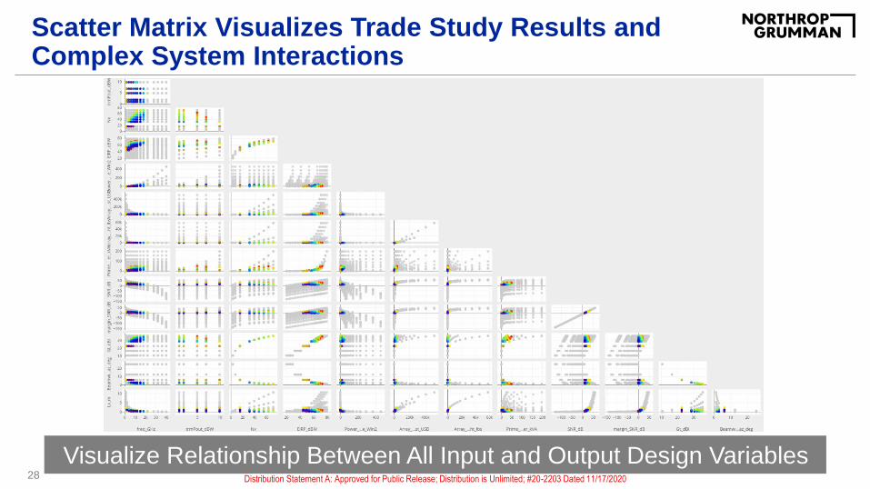
Scatter Matrix Visualizes Trade Study Results and Complex System Interactions
28
Visualize Relationship Between All Input and Output Design VariablesDistribution Statement A: Approved for Public Release; Distribution is Unlimited; #20-2203 Dated 11/17/2020

Built-in Optimization Tools Help Discover Best Design
29
Set to satisfy required link margin while minimizing cost, weight, and powerDistribution Statement A: Approved for Public Release; Distribution is Unlimited; #20-2203 Dated 11/17/2020
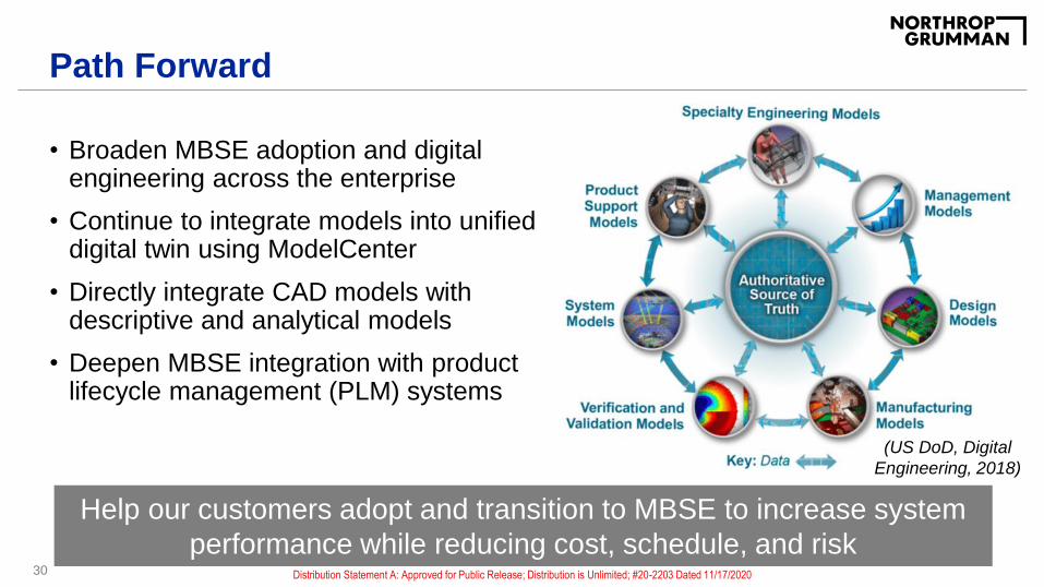
Path Forward
• Broaden MBSE adoption and digital engineering across the enterprise
• Continue to integrate models into unified digital twin using ModelCenter
• Directly integrate CAD models with descriptive and analytical models
• Deepen MBSE integration with product lifecycle management (PLM) systems
30
Help our customers adopt and transition to MBSE to increase system
performance while reducing cost, schedule, and risk
(US DoD, Digital
Engineering, 2018)
Distribution Statement A: Approved for Public Release; Distribution is Unlimited; #20-2203 Dated 11/17/2020
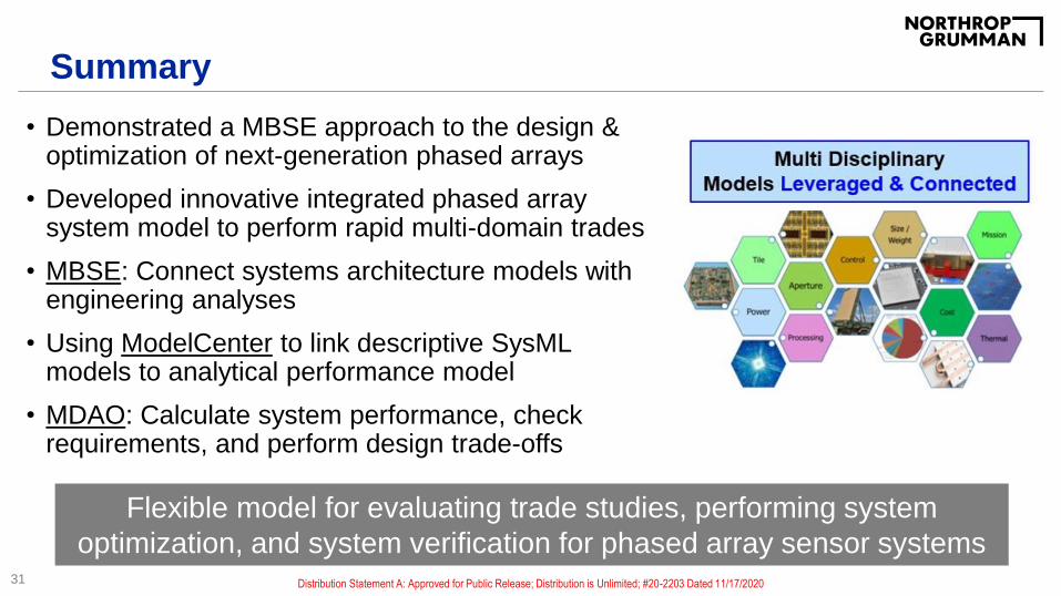
Summary
• Demonstrated a MBSE approach to the design & optimization of next-generation phased arrays
• Developed innovative integrated phased array system model to perform rapid multi-domain trades
• MBSE: Connect systems architecture models with engineering analyses
• Using ModelCenter to link descriptive SysML models to analytical performance model
• MDAO: Calculate system performance, check requirements, and perform design trade-offs
31
Flexible model for evaluating trade studies, performing system
optimization, and system verification for phased array sensor systemsDistribution Statement A: Approved for Public Release; Distribution is Unlimited; #20-2203 Dated 11/17/2020

If you enjoyed today’s talk
32
My 2018 webinar is available on the Phoenix Integration websiteDistribution Statement A: Approved for Public Release; Distribution is Unlimited; #20-2203 Dated 11/17/2020

Acknowledgements
• Phoenix Integration Staff
• My NGC Mentors and Co-workers
33 Distribution Statement A: Approved for Public Release; Distribution is Unlimited; #20-2203 Dated 11/17/2020

Thank You!Contact: [email protected]
34 Distribution Statement A: Approved for Public Release; Distribution is Unlimited; #20-2203 Dated 11/17/2020

35

Value of Modeling Based on Defining Capabilities
36
Analytical: Hardware or Algorithm Driven Capability
Descriptive:
Software or
Relationship
Driven
Capability
Descriptive
Modeling Typically
Adds More Value
Analytical Modeling Typically Adds
More Value
Integrated Analytical and Descriptive
Modeling Solution for Complex
Sensor Systems
Outsource: Likely
Low-Value Activity
This talk
Distribution Statement A: Approved for Public Release; Distribution is Unlimited; #20-2203 Dated 11/17/2020
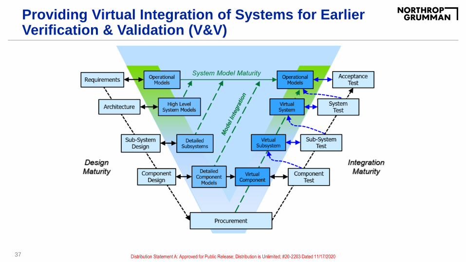
Providing Virtual Integration of Systems for Earlier Verification & Validation (V&V)
37 Distribution Statement A: Approved for Public Release; Distribution is Unlimited; #20-2203 Dated 11/17/2020

Path Forward (Cont.)
38
Reconfigurable Intelligent Metasurfaces Machine Learning Driven Integrated Design
Expand Domains of MBSE & MDAO for Next-Generation Applications
(Hodge, 2020) (Hodge, 2019)
Distribution Statement A: Approved for Public Release; Distribution is Unlimited; #20-2203 Dated 11/17/2020
39
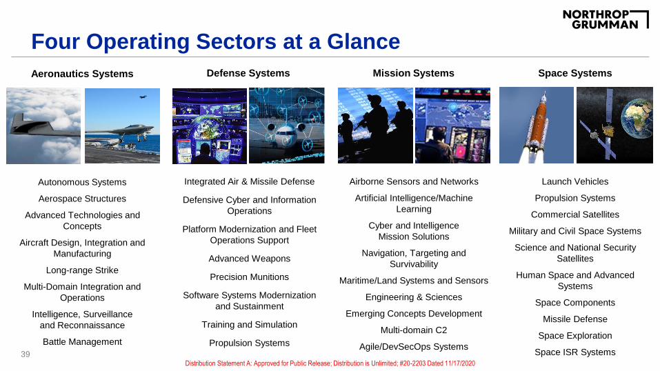
Four Operating Sectors at a Glance
Mission Systems
Airborne Sensors and Networks
Artificial Intelligence/Machine
Learning
Cyber and Intelligence
Mission Solutions
Navigation, Targeting and
Survivability
Maritime/Land Systems and Sensors
Engineering & Sciences
Emerging Concepts Development
Multi-domain C2
Agile/DevSecOps Systems
Autonomous Systems
Aerospace Structures
Advanced Technologies and
Concepts
Aircraft Design, Integration and
Manufacturing
Long-range Strike
Multi-Domain Integration and
Operations
Intelligence, Surveillance
and Reconnaissance
Battle Management
Aeronautics Systems Defense Systems
Integrated Air & Missile Defense
Defensive Cyber and Information
Operations
Platform Modernization and Fleet
Operations Support
Advanced Weapons
Precision Munitions
Software Systems Modernization
and Sustainment
Training and Simulation
Propulsion Systems
Space Systems
Launch Vehicles
Propulsion Systems
Commercial Satellites
Military and Civil Space Systems
Science and National Security
Satellites
Human Space and Advanced
Systems
Space Components
Missile Defense
Space Exploration
Space ISR SystemsDistribution Statement A: Approved for Public Release; Distribution is Unlimited; #20-2203 Dated 11/17/2020