A Minimum Cut Interference-based Integrated RWA Algorithm for
28
A Minimum Cut Interference-based Integrated RWA Algorithm for Multi-constrained Optical Transport Networks Francesco Palmieri Ugo Fiore Sergio Ricciardi Ó Springer Science+Business Media, LLC 2008 Abstract Advances in optical technologies have enabled the deployment of wavelength division-multiplexed (WDM) transmission systems capable of provid- ing huge amounts of bandwidth across long distances. In this scenario, dynamic routing for direct provisioning of optical paths at the WDM layer becomes a challenging problem. Any distributed algorithm for routing dynamic traffic demands on optical transport infrastructures should be simple, flexible, efficient and scalable. The contribution of this paper is a novel integrated routing and grooming scheme for setting-up bandwidth guaranteed paths on hybrid wavelength and label switched networks. Our proposal exploits and refines the minimum interference routing idea according to an improved and re-optimized resource and traffic-aware approach, where critical links are detected and weighted according to a low complexity all- pairs minimum cut strategy that substantially reduce the overall number of calcu- lations and hence the computational cost. The valuable results achieved in the comparison against other well-known reference techniques clearly demonstrate that our algorithm is very time-efficient while performing better in terms of blocking probability. Keywords Optical networks WDM Lightpath RWA Minimum cut F. Palmieri (&) U. Fiore S. Ricciardi Universita ` degli Studi di Napoli Federico II, CSI, Complesso Universitario Monte S. Angelo, Via Cinthia, 80126 Napoli, Italy e-mail: [email protected] U. Fiore e-mail: ugo.fi[email protected] S. Ricciardi e-mail: [email protected] 123 J Netw Syst Manage DOI 10.1007/s10922-008-9097-x
Transcript of A Minimum Cut Interference-based Integrated RWA Algorithm for

A Minimum Cut Interference-based Integrated RWAAlgorithm for Multi-constrained Optical TransportNetworks
Francesco Palmieri Æ Ugo Fiore Æ Sergio Ricciardi
� Springer Science+Business Media, LLC 2008
Abstract Advances in optical technologies have enabled the deployment of
wavelength division-multiplexed (WDM) transmission systems capable of provid-
ing huge amounts of bandwidth across long distances. In this scenario, dynamic
routing for direct provisioning of optical paths at the WDM layer becomes a
challenging problem. Any distributed algorithm for routing dynamic traffic demands
on optical transport infrastructures should be simple, flexible, efficient and scalable.
The contribution of this paper is a novel integrated routing and grooming scheme for
setting-up bandwidth guaranteed paths on hybrid wavelength and label switched
networks. Our proposal exploits and refines the minimum interference routing idea
according to an improved and re-optimized resource and traffic-aware approach,
where critical links are detected and weighted according to a low complexity all-
pairs minimum cut strategy that substantially reduce the overall number of calcu-
lations and hence the computational cost. The valuable results achieved in the
comparison against other well-known reference techniques clearly demonstrate that
our algorithm is very time-efficient while performing better in terms of blocking
probability.
Keywords Optical networks � WDM � Lightpath � RWA � Minimum cut
F. Palmieri (&) � U. Fiore � S. Ricciardi
Universita degli Studi di Napoli Federico II, CSI, Complesso Universitario Monte S. Angelo, Via
Cinthia, 80126 Napoli, Italy
e-mail: [email protected]
U. Fiore
e-mail: [email protected]
S. Ricciardi
e-mail: [email protected]
123
J Netw Syst Manage
DOI 10.1007/s10922-008-9097-x

1 Introduction
While being attractive for their transparent and cost-efficient operation, all-optical
networks need complex routing practices and accurate engineering of WDM paths
to meet the requirements of the dynamic traffic flows that should be transported. A
WDM-based all-optical network consists of wavelength switching devices
interconnected by point-to-point fiber links in an arbitrary mesh topology. On
each fiber, the optical transmission spectrum is carved up into a number of non-
overlapping wavelength bands, often called ‘‘lambdas’’, each supporting a single
communication channel operating at whatever protocol or rate one desires
(transparency). A ‘‘lightpath’’ is an all-optical communication path between a
source device and a destination device behaving as a single hop at the network
layer. The creation of such a path consists of choosing a route in the optical mesh
and one or more wavelengths along that route, providing a logical direct link
between its end nodes. Since wavelengths are a limited resource on each link, the
control plane must keep track of the current allocations and judiciously deal with
oncoming demands. This is referred to as the Routing and Wavelength
Assignment, or briefly RWA problem, whose objective is to minimize the
number of wavelengths used, and to maximize the number of optical paths
successfully set up, ensuring that no two requests sharing a network link are
assigned the same wavelength. The RWA problem, that can be naturally
formulated as an integer linear programming problem, has been shown to be
NP-complete [1]. Furthermore, the complementary problem of routing several
sub-wavelength, lower-rate, requests packaged onto a single wavelength by using
Time Division Multiplexing (TDM) so that the available wavelength bandwidth
would not be exceeded, is called dynamic traffic grooming and it has also been
proved to be NP-hard [2]. RWA, integrated with dynamic traffic grooming, brings
forth the advantage of having a unified control plane paradigm for the modern
mixed TDM and WDM-based network infrastructures, handling resources both at
the IP and the optical layer. Our work focuses on such dynamic online integrated
RWA problem, where incoming connection requests are routed on the optical
transport network using the current state of the network, such as link load and
wavelength usage, and with the main objective of minimizing the total blocking
probability in the entire network, that is the fraction of connection requests that
get rejected. Here, each connection request can be viewed as a dedicated
communication channel between two network nodes characterized by specific
service quality parameters. Specifically, in our model requests have a specific QoS
agreement on bandwidth, although our algorithm can also perform routing based
on other QoS metrics such as limited latency, error rate, etc. that can be
incorporated into SLAs by converting these requirements into a bandwidth
requirement as shown in [3]. We propose a novel approach, that can be viewed as
an evolution of the minimum interference routing scheme (described in Sect. 3),
based on a two-stage, grooming-capable, integrated dynamic RWA algorithm
working at the control-plane layer on each involved network element. We
considered the minimum interference idea very promising, for it implicitly
exploits any available knowledge of the network ingress–egress points for
J Netw Syst Manage
123

potential future demands, even though the demands themselves are unknown, and
defers, as possible, loading of ‘‘critical’’ links that, if saturated, would make some
possible future demands impossible to satisfy. Our main objective has been to
drastically reduce the computational time, and, at the same time, minimize the
total blocking probability by optimizing bandwidth, cost and length of designed
paths, and, finally, to keep the network resource usage fairly balanced, trying to
leave on each link as much free capacity as possible to satisfy further requests.
Similarly to the traditional minimum interference routing paradigm, the proposed
scheme operates independently from specific traffic profiles. It also provides a
flexible and fully dynamic path selection scheme, based on state, characteristics
and capacity information for each link, with a grooming policy that is not
predetermined but may vary along with the evolution of the network traffic.
Additionally, our RWA paradigm can efficiently handle sparse wavelength
conversion capability, and can account for all the complexity, performance and
resource-limitation constraints implicit in the various flavors of optical switches.
More specifically, it explicitly penalizes all lightpaths that require wavelength
conversion—this may be particularly useful if the cost associated with wavelength
conversion is high (for example, if wavelength conversion is performed in the
electronic domain). Finally, we adopted a totally flexible network model,
supporting heterogeneous WDM equipment, in which the number and type of
lambdas can be specific for each link. In the following we will refer to our
algorithm as MICRA (MInimum-Cut interference-based Routing Algorithm).
Extensive simulations have been carried out to evaluate the performance of
MICRA in terms of total available bandwidth between ingress and egress nodes
after routing a new request, as well as lightpath request rejection probability.
Compared to other well-known routing algorithms, our approach seems to perform
significantly well. Specifically it demonstrated the capabilities of achieving a
better load balance and resulting in a significantly lower blocking probability at a
much lower computational complexity. This makes the proposed on-line dynamic
RWA algorithm very attractive for the modern multilayer optical circuit switched
and optical wavelength switched networks.
The remainder of this paper is organized as follows: Sect. 2 describes the related
work available in the literature, Sect. 3 introduces the network model on which our
algorithm works, Sects. 4 and 5 respectively explain the common minimum
interference approach, based on the maximum flow calculation and how to get from
the maximum flow to the minimum cut in order to determine the critical links
efficiently, Sect. 6 specifies how we exploit the Stoer–Wagner minimum cut
algorithm to obtain a measure of the criticality for each link of the network and
defines how to calculate this criticality score, while Sect. 7 presents the weighting
function used by our algorithm which takes into account also other important factors
as the type of conversion devices involved and QoS properties. In Sect. 8 we
accurately detail our algorithm and its complete operation framework, in Sect. 9 we
analyze the computational space and time complexity, and finally, in Sect. 10 we
show the performances and the result analysis of our algorithm compared to other
well-known algorithms, and in Sect. 11 we draw the conclusions and the possible
future works.
J Netw Syst Manage
123

2 Related Work
Many heuristic methods have been developed to deal in a computationally feasible
time with such a challenging problem [4]. The distributed dynamic routing
algorithms proposed in [5] specifies a common framework for different types of
QoS using additive and multiplicative metrics to achieve dedicated and shared
protection for single link failures and considers traffic demands at the wavelength
level but not at sub-wavelength level. The profile-based routing solution proposed in
[6] strictly relies on the availability of precise traffic profiles between pairs of
ingress and egress routers. However, such a priori knowledge may not be easily
obtainable and reliable. Analogously, [7] proposes an integrated routing and
grooming algorithm for IP over WDM networks based on a ‘‘blocking island’’
hierarchical network model. Whereas the main idea of the algorithm is to keep the
integrity and load balance of related blocking islands as intact as possible, the
paradigm suffers of the same drawbacks described above for the profile-based
solution. An efficient low-cost algorithm for routing of bandwidth-guaranteed
tunnels in general topology networks has been presented in [8]. It is based on a hop-
constrained adaptive Bellman-Ford shortest path variation (HCASP) developed to
achieve two simultaneous objectives: limiting the length of the chosen path between
the ingress–egress pair and giving preference to less loaded links at the time of path
establishment. Unfortunately, HCASP achieves higher LSP rejection ratios than
MIRA in networks with high degree of connectivity and small network diameter,
whereas it performs better than MIRA for networks with a low degree of
connectivity and large diameters. In [9] an approach based on a Less Influence Path
First (LIPF) algorithm is presented, outperforming the conventional RWA LIPF-
based algorithms. It takes into account, among the other traditional factors, also the
hops of each alternative route and the position of each link in this network.
Furthermore, [10] proposes a new method called successive sub-problem solving
(SSS), based on a concept we developed for production scheduling within the
Lagrangian relaxation framework. The essence of this method is to introduce
coupled penalty terms and to apply surrogate sub-gradient to generate a proper
search direction at the high level, simultaneously preserving all the advantages of
Lagrangian relaxation such as computational efficiency, quantitative measure of
solution quality, etc. Finally, in [11] a parametric adaptive dynamic grooming-
capable RWA heuristic scheme based on K-shortest paths (SPARK) has been
presented. Such algorithm is transparent with respect to the presence of wavelength
converters and achieves very low connection rejection ratios with minimal
computational complexity, selecting the best route among multiple feasible paths
by evaluating a goodness function on each candidate path, whereas the MICRA
approach considers the minimum cut between all node pairs.
3 Background
This section briefly introduces some of the basic concepts that will be useful to
better explain the proposed integrated RWA/grooming paradigm, by presenting the
J Netw Syst Manage
123

underlying optical network architectural scenarios, protocols and the network model
that will be used.
3.1 State-of-the-Art Optical Networking Scenario
The modern optically-empowered transport infrastructure can be physically seen as
a mesh of variously interconnected optical or traditional electronic TDM sub-
networks. In particular, WDM-switched optical sub-networks are typically used as
backbone infrastructures (Fig. 1).
The nodes operating on the optical transport backbone can be optical cross-
connects (OXC) or IP/GMPLS routers, namely Label/Lambda Switching Routers
(LSRs), connected to OXCs with native WDM interfaces. Whereas an LSR can
multiplex or demultiplex traffic at any granularity, an OXC can only switch traffic at
wavelength granularity, that is explicitly cross-connecting specific wavelengths
from each input port to the appropriate output ports. Depending on the technology
used, an OXC may or may not be able to perform wavelength conversion. The
requirement that a specific lightpath, to avoid the need of expensive conversion
devices, should use the same wavelength on all the links of the chosen route, is
commonly known as the wavelength continuity constraint.
3.2 The GMPLS Control Plane
Generalized Multi-Protocol Label Switching (GMPLS) [12], is emerging as the
candidate unified control-plane solution for integrated RWA in next-generation
optical networks. GMPLS integrates in a native and natural way the widely
known generalized label swapping/forwarding paradigm with the emerging
optical network layer routing practices. Simply stated, integrated RWA based
on GMPLS technologies is essentially based on classic constraint-based routing
optimization methods, realized through the provisioning of explicit alternate
Fig. 1 The typical optical transport network architecture
J Netw Syst Manage
123

label/lambda-switched paths, called LSPs. For optimal LSP displacement, dynamic
on-line network optimization is required, with the objective of maximizing the
resource utilization according to cost and performance criteria. A subset of the LSRs,
and specifically those located on the network edge, are the ingress–egress nodes
between which LSPs are to be set up dynamically at each request. A sub-wavelength
connection request (an electronic LSP or pure label switched path) could be routed
over a direct lightpath (a single-hop path at the IP level) connecting an ingress router
to an egress router or over a sequence of lightpaths (a multi-hop path at the IP level),
crossing many intermediate LSRs along its route. To obtain topology and resource
usage information for such integrated routing, we need to consider both routers and
OXCs as being in the same unified control-plane domain, and running an enhanced
link state routing protocol on both routers and OXCs. This protocol has to distribute
both link-state and resource usage information to all network elements that will share
a common network view. At the IP layer, OSPF (or ISIS) extensions similar to those
proposed in [13] can be used to distribute bandwidth usage information. At the
optical layer, these protocols can be used to distribute wavelength usage information
for each link. Additional extensions to indicate specific properties of OXCs (such as
wavelength conversion capability) may also be needed. Finally, in an integrated
RWA environment, the amount of control messages flowing across the network to
maintain accurate status information may be substantial and must be kept under
control. The authors in [14] stress the importance of this respect and propose that
only a type of synthetic control information, namely the number of lightpaths that can
be established between a pair of nodes, is to be exchanged across layers.
3.3 Building the Network Model
Now that we have stated the problem, we can formally define the network model on
which our algorithm works. We consider an optical network consisting of n nodes
interconnected by l bi-directional optical links (fibers), represented as a multigraph
G = (V, E), where each edge corresponds to an individual channel (wavelength).
Each fiber f can support up to kf channels, and there can be more than one fiber
connecting the same pair of nodes. The multigraph construction process is sketched
in Fig. 2 below.
An edge x [ E and its status may be represented by a 6-uple (ux, vx, fx, kx, gx, rx)
where ux and vx are the extremes, fx is an index associated to the physical link or fiber
number, kx corresponds to the logical channel number or wavelength index on the
fiber fx, gx and rx are respectively the total and the residual wavelength capacity in
bandwidth units. Note that our fiber links may support a different number of
wavelengths and that wavelengths on different fibers may have diverse maximum
capacities gx, according to the features of the WDM equipment involved. Each node
in the network can be a lambda-edge router with several WDM interfaces and
electronic wavelength conversion capability or a pure OXC with or without
wavelength conversion capability. Nodes v [ V are represented by a couple (v, pv)
where v is the vertex number in the graph and pv is a wavelength conversion
capability attribute. The conversion capability attribute values have been specifically
J Netw Syst Manage
123

defined to implicitly represent the complexity and expensiveness, in performance
terms, of the conversion devices, so that:
pv ¼
1
2
4
8
Transparent OXCOpaque OXC
Lambda Switching RouterRouter
8>><
>>:
ð1Þ
We may weight edges according to the nodes they are incident to; we use (2) to
take into account the type of conversion devices that the edge x links:
HðxÞ ¼Y
v 2 VðxÞpv ð2Þ
where x [ E is an edge, V(x) is the set of the two nodes that are extremes of the edge
x and pv is the conversion capability of the node v defined in (1).
Each time a new lightpath needs to be established between an ingress–egress pair of
nodes in our multi-graph, we modify it by zeroing the available capacity on the graph
edges traversed by the lightpath (corresponding to the wavelength used) and by adding
a direct edge x, henceforward called cut-through edge (see, e.g., [15]), with capacity gx
set to gmin and residual capacity rx set to gmin - b, where b is the fraction of the link
bandwidth required by the lightpath and gmin is the minimum global wavelength
capacity between all the edges belonging to the lightpath. A cut-through edge can be
used in any path selection operation and thus can participate in one or more LSPs as a
single virtual edge (a single hop at the IP layer) terminated on lambda-edge router
nodes. When an established lightpath is torn down because the last connection
occupying it is ended, the cut-through edge is removed and the edges in the extended
graph corresponding to the underlying physical links are set back with full capacity.
This schema allows to flexibly model nearly any network topology and to consider
Fig. 2 Generating the working multi-graph
J Netw Syst Manage
123

node conversion capabilities, wavelength availability and residual bandwidth per
logical link at the IP layer. Each new connection request can be routed over a direct
lightpath modelled as a single cut-through edge in our multi-graph, or over a sequence
of lightpaths (a multi-hop path at the IP level, where each hop can be a lightpath), if it
crosses lambda-edge or routers as well that will link together lightpaths.
4 The Minimum Interference Paradigm
Most of the existing integrated RWA schemes operate by considering the topology
of the network and, to perform traffic grooming, the residual capacities on the links,
but do not take into account the location of the ingress/egress nodes, that probably
will serve as the source and destination of future traffic. If each routing decision is
taken oblivious to the location of these ingress and egress points of traffic then we
most likely may ‘‘interfere’’ with the routing of some future demands. Conse-
quently, the objective of an optimal RWA algorithm is the accommodation of as
many requests as possible without requiring any knowledge regarding future traffic
demands and at the same time minimizing each possible interference with them. The
best idea that can be used to achieve this is to pick for the current request a path
such that after the request is routed the residual available capacity between the
ingress–egress pairs is maximized, so that we can defer loading on links or
lightpaths which may be important to satisfy future demands. We define the residual
capacity of a link or lightpath to be the difference between the nominal bandwidth
of the link and the sum of the LSP demands that are routed on it. Note that a new
LSP can be routed along a given link only if the residual bandwidth on that link
exceeds the bandwidth requested by the new LSP.
One of the most interesting routing schemes, working on the above concepts is
called Minimum Interference Routing Algorithm (MIRA) [16], based on an
heuristic dynamic online path selection algorithm. The basic observation from
which the algorithm originates is that routing an LSP along a path between a
specific ingress–egress pair can reduce the maximum available bandwidth between
some other ingress–egress router pairs. This phenomenon best describes the concept
of ‘‘interference’’ explained above. The key idea is to avoid routing over ‘‘critical’’
links that could ‘‘interfere’’ with potential future paths set-up. The same concept,
transposed in the optical domain, is the basis of an integrated RWA and grooming
algorithm, known as Maximum Open Capacity routing Algorithm (MOCA) [17]. By
considering an auxiliary graph which takes into account both IP and WDM layer
information, MOCA determines whether to route an incoming LSP request over the
existing topology or is better to open a new lightpath. Then, for routing over the
existing IP layer topology, it computes ‘‘good’’ label switched paths, while for new
wavelengths setup it determines ‘‘good’’ lightpaths. The ‘‘goodness’’ of a path is
based on extensions of the MIRA algorithm: in order to maximize the future
requests allocation, it is better to route new LSPs along paths which minimize the
‘‘interference’’ or maximizes the open capacity between an ingress–egress routers
pair. Thus, after determining the critical links, the same ‘‘criticality’’ concept can be
used as an interference-related weighting factor to select the best (least interfering)
J Netw Syst Manage
123

paths by using a traditional Dijkstra-based searching algorithm. Unfortunately, due
to the close behavior of MOCA to MIRA, this algorithm suffers from the same main
drawbacks that are:
• the identification of the ‘‘critical’’ links by the actual maximum flow calculation
performed each time a new LSP has to be established leads to a severe
computation complexity;
• the algorithm cannot estimate bottlenecks on links that are ‘‘critical’’ for clusters
of nodes [18];
• MIRA can lead to an unbalanced network utilization because it does not take
into account the current traffic load in routing decisions [19].
Our proposal uses the minimum interference concept as a reference routing strategy,
and focuses its efforts on reducing the computation complexity of MIRA/MOCA by
using a different aggregated mechanism to identify ‘‘critical’’ links. It also carefully
considers the current network load and the available link and lightpath capacities to
cope with the above unbalancing and blocking effects.
5 Determining the Critical Links
The ‘‘critical’’ links can be identified as links that, if heavily loaded, would make it
impossible to satisfy future demands between some ingress–egress pairs. We would
like to estimate the network capacity between the different ingress–egress pairs. We
determine this capacity by computing the maximum flow of traffic that can be sent
from the ingress to the egress over the network where the capacity of a link is the
current residual capacity. Thus, we can define the interference between two given
paths p and q between the source–destination pair of nodes (s,d), as the reduction in
maximum flow value between that ingress–egress pair due to the routing of
bandwidth-specific connections on that path. Consequently, critical links become
links with the property that whenever an LSP is routed over them, the maximum
flow values of one or more source–destination pairs decreases. The maximum flow
provides an upper bound on the amount of traffic demand that can be routed
between the ingress–egress pair, since a given demand cannot be split across
multiple paths. Nevertheless, the maximum flow provides a good estimation of the
available capacity between different ingress–egress pairs. In fact, if the maximum
flow between a given ingress–egress pair is zero, then no further demand can be
routed between that ingress–egress pair and any connection request will be blocked
until sufficient residual capacity will be available again on the critical links.
Consequently, the maximum flow depends on the residual capacity of the critical
links in the network, and thus also the connection rejection/blocking ratio, that is
our most important minimization objective.
5.1 Performance Tradeoffs
While it is widely recognized that the idea of routing over non interfering links is a
sound and logical one, the computation time that would be required makes it
J Netw Syst Manage
123

impractical to calculate the maximum flow for each ingress/egress pair. Therefore,
heuristics have been devised with the objective of trying to identify the critical links
in a time compatible with an industrial-strength implementation [17]. In fact, when
a new connection needs to be routed over a network with n nodes and m links by
using the traditional minimum interference approach, the maximum flow between
each ingress–egress pair nodes has to be computed in O(n3) [16] before applying the
traditional SPF algorithm. Suppose there are p source–destination pairs in the
network (not all nodes may be able to generate/terminate traffic); we need pmaximum flow calculations to determine the set of critical links each time a path
setup request arrives. In the worst case, where every node is a source node for every
other node, p becomes O(n2). This implies a worst-case computational complexity
of roughly O(n5), that is obviously unacceptable. Clearly the most critical
component in such calculation is the maximum flow computational complexity
that, even if it can be improved to O(nm log(n2/m)) by using the Goldberg and
Tarjan’s algorithm [20], leads in any case to a complexity that is more than one
order of magnitude higher than the traditional SPF algorithm. An alternative lower
cost strategy for critical link determination, avoiding the maximum flow calculation,
is definitely needed.
5.2 A New Strategy for Critical Links Calculation: From the Maximum Flow
to the Minimum Cut
By considering linear programming duality properties [21], we can pass from the
maximum flow between two nodes to the corresponding minimum cut, that can be
defined as a partition of the network nodes into two nonempty sets minimizing the
total weight of the edges crossing between them. More formally, a cut (A, B) of a
graph G with n vertices and m edges, each weighted with its residual capacity, is a
partition of the vertices of G into two nonempty sets A and B. An edge (v, w)
belongs to cut (A, B) if either v or w is in A and the other in B. The value of a cut is
the number of edges that cross the cut or, in a weighted graph, the sum of the edges’
weights that cross the cut. The minimum-cut between two nodes s, t is the cut of
minimum value with s 2 A and t 2 B. The all-pairs minimum cut problem is to find
the cut of minimum value in the whole graph G regardless of vertex s and t, that is
finding a minimum cut for any pair (s, t).The widely known Max-Flow-Min-Cut-Theorem by Ford and Fulkerson [22]
showed the duality of the maximum flow and the minimum cut between a source–
destination pair. There, if s and t are two vertices that are the source and the sink in a
maximum flow problem, they have to be separated by the minimum cut between sand t, that is, they have to lie in different partitions of the graph. Since a maximum
flow between s and t saturates every minimum cut between the same nodes, it is
straightforward to find an s–t minimum cut given a maximum flow between s and tand vice versa. Thus, if the capacity of any of the links in the minimum cut is
decreased, the maximum flow value between that ingress–egress pair decreases.
This means that the number of demands which can be routed between this ingress–
egress pair in the future decreases. Therefore, we define all the links that belong to
J Netw Syst Manage
123

the minimum cut for an ingress–egress pair to be critical to that ingress/egress pair.
Since there may be more than one minimum cut for a ingress–egress pair, all arcs
belonging to any minimum cut are defined to be critical for that pair.
It is worthwhile to note that the determination of the critical links has to be done
between all the source–destination node pairs. Whatever the speed at which we can
find the minimum cut, computing the minimum cut for each ingress/egress pair will
definitely have an unacceptable performance impact. Let us start by observing that
the most critical links in the entire network are undoubtedly those that belong to the
global, all-pairs, minimum cut. Consequently, we would like to avoid the minimum
cut calculation for each source–destination pair by using a network-wide aggregate
minimum cut calculation that can operate simultaneously for all the pairs in a single
pass. We will therefore focus our attention towards an approach, as simple and
flexible as possible, that provides us with an estimation of all the critical links
through the calculation of the global minimum cut.
5.3 Efficiently Finding the Global Minimum Cut: the Stoer–Wagner Approach
The traditional approach to calculate the minimum cut was based on its close
relationship to the maximum flow problem. Hao and Orlin [23] showed how to use
the maximum flow algorithm by Goldberg and Tarjan [20] in order to solve the
minimum cut problem in time O(nm log(n2/m)), nearly as fast as the fastest
maximum flow algorithms so far, which is however our computationally unaccept-
able starting point that needs improvement. Thus our main requirement is to avoid
any flow based approach. Nagamochi and Ibaraki [24] described the first minimum
cut algorithm that used no flow-based techniques at all. The central idea is to
construct the spanning forests and repeatedly identify and contract edges that are not
in the minimum cut, until the minimum cut becomes apparent. This leads to an
asymptotic runtime of O(nm + n2 log n) on undirected graphs with nonnegative real
edge weights. Their approach was refined in [25] by Stoer and Wagner. The
algorithm of Stoer and Wagner works in n - 1 phases. In each phase it identifies
two vertices and a minimum cut separating them and then collapses the two vertices
into one. The global minimum cut is the minimum between all the cuts found in any
phase. Each phase runs in time O(m + n log n). The Stoer–Wagner approach is
remarkable because it does not use any maximum flow technique as a subroutine.
Somewhat surprisingly, the algorithm is very simple in contrast to all the other
algorithms (flow-based and non-flow-based) that were published so far. In principle,
each phase of the algorithm is very similar to Prim’s minimum spanning tree
algorithm and the Dijkstra’s shortest path computation (improved by a Fibonacci
heap), which leads to an equivalent running time of O(m + n log n) per phase and
an overall time complexity of O(nm + n2 log n). After choosing an arbitrary start
vertex, the algorithm maintains a subset of vertices A that is initialized with the start
vertex and that grows by repeatedly incorporating the most adjacent vertex to A, i.e.
a vertex v not belonging to A that has a maximum sum of weights for its connections
to vertices in A. If all vertices have been added to A, the last two vertices, s and t, are
merged into one. While edges between s and t are simply deleted by the contraction,
all edges from s and t to another vertex are replaced by an edge weighted with the
J Netw Syst Manage
123

sum of the old weights. The cut that separates the vertex last added from the rest of
the graph is called the cut-of-the-phase. Thus, by induction on the number of
vertices, the minimum capacity cut of the graph is the cut-of-the-phase having
minimum weight. Figure 3 below sketches the behaviour of the Stoer–Wagner
algorithm. Upper case letters are vertex names, lower case letters show the order of
addition to the set S. The minimum cut {ABDEG} | {CFH} has capacity 3 and is
found in the third phase (f). The simple and time efficient approach used by Stoer–
Wagner algorithm together with its stepwise structure, make this technique the ideal
to perfect suit our aims.
6 Aggregating the Critical Link Calculations
When calculating an all-pairs minimum cut with the Stoer–Wagner algorithm, we
implicitly determine, during each of the n - 1 phases, a feasible cut in the graph
with its corresponding weight. Such computational by-products implicitly can give
us information about all the ‘‘candidate’’ critical links and a measure of criticality
associated with each of them. More precisely, all the links belonging to the
minimum cut will be obviously the most critical ones, so they will be assigned the
maximum score in terms of ‘‘criticality’’. Similarly, links belonging to the other cut-
of-the-phases will be assigned an estimated criticality score proportional to the
weight of the corresponding cut. Note that the Stoer–Wagner algorithm works
stepwise, by successive s–t vertex contractions, in which the edges that are removed
(those connecting s to t) belong to the cut-of-the-phase. The processing ends when
Fig. 3 The Stoer–Wagner minimum cut algorithm in action
J Netw Syst Manage
123

only the initial vertex and the aggregate of the others remain, so every edge will be
sooner or later involved into a cut-of-the-phase. Thus, in a single application of the
minimum cut algorithm we can simultaneously determine all the critical links and
their corresponding weights, or criticality scores. The criticality score S(x) assigned
to each link x, can be determined from the weight of the cut C as:
S xð Þ ¼ 1
W Cð Þ ð3Þ
where C is the minimum cut containing the critical link x and W(C) is its total
weight of the cut C, defined as:
W Cð Þ ¼X
e2C
re ð4Þ
The properly modified Stoer–Wagner algorithm for determining all the critical
links and their criticality score is reported in Fig. 4, where the functions S(x) is
defined in (3).
At the end of the n - 1 phases the non-critical links will have the lowest score
and all the critical ones will be weighted according to their criticality score.
Now, it is natural to ask whether we can further improve the overall performance
by reducing the number of times the all-pairs minimum-cut calculations are done. It
is worthwhile examining whether it is necessary to recalculate the critical links after
each LSP is routed. Note that without critical link computation, each LSP routing
involves only a shortest-path computation. The recalculation of the critical links,
and hence of the minimum cut, is really needed only when we have a change in the
Criticality Scores calculation via Stoer-Wagner Minimum cut
Input : An undirected graph G = (V,E) with |V|=n, |E|=mOutput: The criticality score vector Smax [1 .. m]Choose an arbitrary start vertex a;Smax [1 .. m] ← 0;V’ ← V;while |V’| > 1 do
A ← {a};while A ≠ V’ do
Add to A the most tightly connected vertex; Adjust capacities between A and vertices in V’ \ A;
end while C := cut of V’ separating the last added vertex from others;for each edge x in C
if S(x) > Smax [x] thenSmax [x] ← S(x);
end if end for Merge the two vertices that were added last to A;
end while return Smax;
Fig. 4 The criticality score calculation pseudo-code
J Netw Syst Manage
123

network topology (a new lightpath is established or deleted and the associated cut-
through edge created or destroyed) or when there is a residual capacity change on a
critical link (a new traffic grooming LSP traversing the link is established or
deleted). Here we can make the choice of running a recalculation only when the
involved link presents a significant degree of criticality. In an highly connected
network mesh with a few critical links, this behaviour can imply a substantial
performance improvement. The definition of a critical link significance deserves
some investigation. One could think of define significant every link whose criticality
is within some constant percentage range from the minimum cut; however, links
with widely differing capacities would be equally significant under that definition. If
we define significance on the basis of the criticality being higher than a fixed
absolute value, significance would be independent of the actual aggregated capacity
of the network. It is then better to say that a link is significant when its criticality
factor is the higher part of the range. Let us denote by kWi = W(kCi) the capacity of
the i-th cut-of-the-phase in the k-th execution of the Stoer–Wagner algorithm.
Let also Wmax be the maximum of the capacities of all the cuts determined so far
(during the first k executions),
Wmax ¼ maxk
maxi
1Wif g� �
ð5Þ
Now, we say that a link is significant when its criticality factor exceeds a
parametric threshold, determined by a parameter a 2 0; 1½ � . Since, for all the cut-of-
the-phase capacities, 1 � kWi�Wmax, and thus
1
Wmax
� 1
kWi� 1 ð6Þ
the criticality on the link x is significant if
S xð Þ� 1� aWmax � 1
Wmax
ð7Þ
The criticality score associated with a significant link must therefore satisfy the
following
S xð Þ� 1� að ÞWmax þ aWmax
ð8Þ
Note that if a = 0, no link is significant; if a = 1 every link is significant.
7 Balance Network Utilization
Once the critical links have been identified, we would like to avoid routing LSPs on
critical links to the extent possible. We can simply do this by working on a graph
where the critical links will be increasingly weighted according to their ‘‘critical-
ity’’. Here we could use our criticality scores, calculated according to the previously
presented algorithm, to defer loading of critical links whenever possible. The actual
explicit route can hence be calculated by using a shortest path computation (using
Dijkstra’s algorithm on the weighted graph) as in other routing schemes. Clearly,
J Netw Syst Manage
123
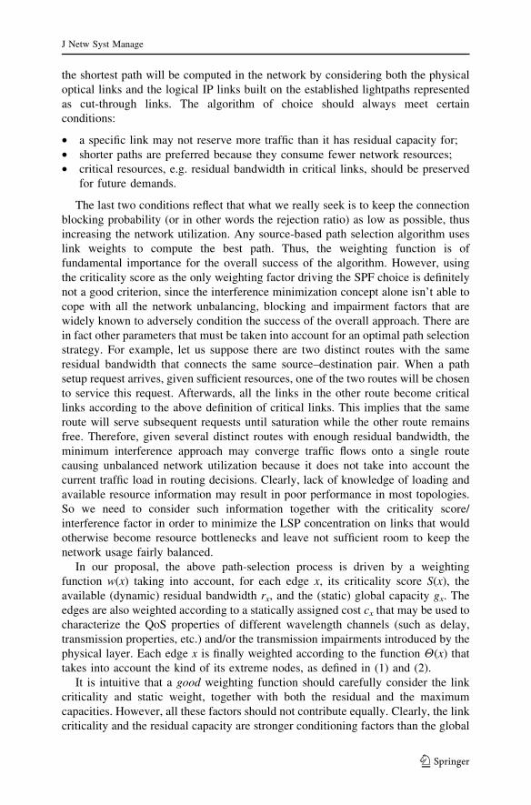
the shortest path will be computed in the network by considering both the physical
optical links and the logical IP links built on the established lightpaths represented
as cut-through links. The algorithm of choice should always meet certain
conditions:
• a specific link may not reserve more traffic than it has residual capacity for;
• shorter paths are preferred because they consume fewer network resources;
• critical resources, e.g. residual bandwidth in critical links, should be preserved
for future demands.
The last two conditions reflect that what we really seek is to keep the connection
blocking probability (or in other words the rejection ratio) as low as possible, thus
increasing the network utilization. Any source-based path selection algorithm uses
link weights to compute the best path. Thus, the weighting function is of
fundamental importance for the overall success of the algorithm. However, using
the criticality score as the only weighting factor driving the SPF choice is definitely
not a good criterion, since the interference minimization concept alone isn’t able to
cope with all the network unbalancing, blocking and impairment factors that are
widely known to adversely condition the success of the overall approach. There are
in fact other parameters that must be taken into account for an optimal path selection
strategy. For example, let us suppose there are two distinct routes with the same
residual bandwidth that connects the same source–destination pair. When a path
setup request arrives, given sufficient resources, one of the two routes will be chosen
to service this request. Afterwards, all the links in the other route become critical
links according to the above definition of critical links. This implies that the same
route will serve subsequent requests until saturation while the other route remains
free. Therefore, given several distinct routes with enough residual bandwidth, the
minimum interference approach may converge traffic flows onto a single route
causing unbalanced network utilization because it does not take into account the
current traffic load in routing decisions. Clearly, lack of knowledge of loading and
available resource information may result in poor performance in most topologies.
So we need to consider such information together with the criticality score/
interference factor in order to minimize the LSP concentration on links that would
otherwise become resource bottlenecks and leave not sufficient room to keep the
network usage fairly balanced.
In our proposal, the above path-selection process is driven by a weighting
function w(x) taking into account, for each edge x, its criticality score S(x), the
available (dynamic) residual bandwidth rx, and the (static) global capacity gx. The
edges are also weighted according to a statically assigned cost cx that may be used to
characterize the QoS properties of different wavelength channels (such as delay,
transmission properties, etc.) and/or the transmission impairments introduced by the
physical layer. Each edge x is finally weighted according to the function H(x) that
takes into account the kind of its extreme nodes, as defined in (1) and (2).
It is intuitive that a good weighting function should carefully consider the link
criticality and static weight, together with both the residual and the maximum
capacities. However, all these factors should not contribute equally. Clearly, the link
criticality and the residual capacity are stronger conditioning factors than the global
J Netw Syst Manage
123
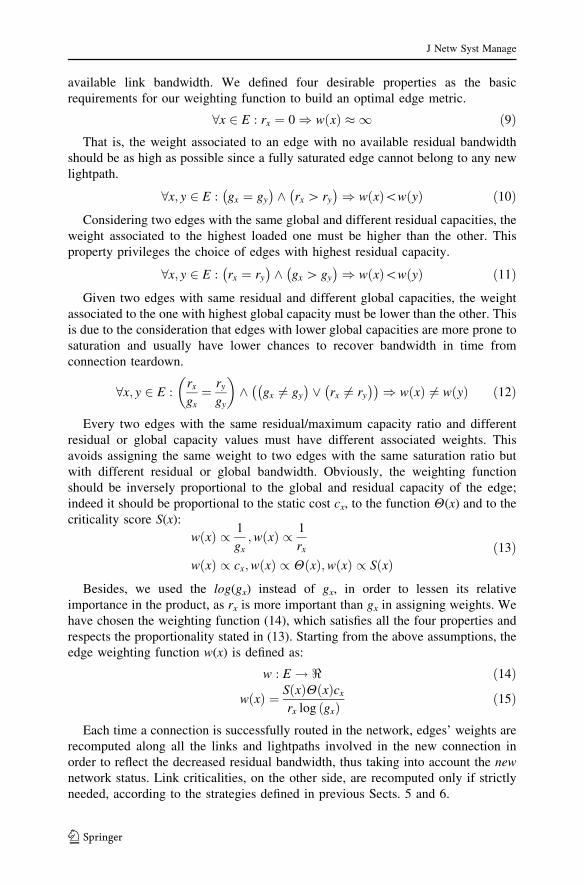
available link bandwidth. We defined four desirable properties as the basic
requirements for our weighting function to build an optimal edge metric.
8x 2 E : rx ¼ 0) w xð Þ � 1 ð9ÞThat is, the weight associated to an edge with no available residual bandwidth
should be as high as possible since a fully saturated edge cannot belong to any new
lightpath.
8x; y 2 E : gx ¼ gy
� �^ rx [ ry
� �) w xð Þ\w yð Þ ð10Þ
Considering two edges with the same global and different residual capacities, the
weight associated to the highest loaded one must be higher than the other. This
property privileges the choice of edges with highest residual capacity.
8x; y 2 E : rx ¼ ry
� �^ gx [ gy
� �) w xð Þ\w yð Þ ð11Þ
Given two edges with same residual and different global capacities, the weight
associated to the one with highest global capacity must be lower than the other. This
is due to the consideration that edges with lower global capacities are more prone to
saturation and usually have lower chances to recover bandwidth in time from
connection teardown.
8x; y 2 E :rx
gx¼ ry
gy
� �
^ gx 6¼ gy
� �_ rx 6¼ ry
� �� �) w xð Þ 6¼ w yð Þ ð12Þ
Every two edges with the same residual/maximum capacity ratio and different
residual or global capacity values must have different associated weights. This
avoids assigning the same weight to two edges with the same saturation ratio but
with different residual or global bandwidth. Obviously, the weighting function
should be inversely proportional to the global and residual capacity of the edge;
indeed it should be proportional to the static cost cx, to the function H(x) and to the
criticality score S(x):
w xð Þ / 1
gx;w xð Þ / 1
rx
w xð Þ / cx;w xð Þ / H xð Þ;w xð Þ / S xð Þð13Þ
Besides, we used the log(gx) instead of gx, in order to lessen its relative
importance in the product, as rx is more important than gx in assigning weights. We
have chosen the weighting function (14), which satisfies all the four properties and
respects the proportionality stated in (13). Starting from the above assumptions, the
edge weighting function w(x) is defined as:
w : E ! < ð14Þ
w xð Þ ¼ S xð ÞH xð Þcx
rx log gxð Þð15Þ
Each time a connection is successfully routed in the network, edges’ weights are
recomputed along all the links and lightpaths involved in the new connection in
order to reflect the decreased residual bandwidth, thus taking into account the newnetwork status. Link criticalities, on the other side, are recomputed only if strictly
needed, according to the strategies defined in previous Sects. 5 and 6.
J Netw Syst Manage
123

8 Putting All Together
The proposed integrated RWA algorithm operates online, running at each request of
a dedicated connection with specific QoS requirements (typically bandwidth
capacity) between two network nodes. For completeness and flexibility sake we
make no specific assumption on the number of wavelengths per fiber, number of
fiber on each link and on the presence of wavelength conversion devices on the
network. All these parameters are fully and independently configurable on each fiber
link or network device at the network topology definition time. Instead, we require
that all the network nodes operate under a unique control-plane and share a common
network view by relying on a common link-state protocol that is used to distribute
resource usage information. Furthermore, we also assume that every connection is
bidirectional and consists in a specific set of traffic flows that cannot be split among
multiple paths. Each connection can be routed on one or more (possibly chained)
existing lightpaths between its source and destination nodes, with sufficient
available capacity or on a new lightpath dynamically built on the network upon the
existing optical links. Grooming decisions are taken instantaneously reflecting an
highly adaptive strategy that dynamically tries to fulfill the algorithm’s network
resource utilization and connection serviceability objectives. In detail, as a new
request arrives, the control plane on each node, starting from the originating one,
runs the SPF algorithm based on the cost function presented above and the last
known criticality scores (determined on the previous run or at the initialization
time), and triggers the proper path setup actions:
• it first determines if the request can be routed on one of the available lightpaths,
by time-division multiplexing it together with other already established
connections, or a new lightpath is needed on the optical transport core to join
the terminating (edge) nodes. In presence of multiple options between new
feasible and already established lightpats, the weighting function (15), together
with the grooming and the lambda conversion costs, applied on the existing
lightpaths and on the wavelength links that can be used to set up new lightpaths,
dynamically determine the least-cost routing for the request, on the current
network status basis. For example, if two lightpaths between the source and
destination nodes exist, both with sufficient available capacity, the tie is resolved
in favor of the least-cost lightpath. Such a policy guarantees maximum lightpath
utilization and automatically achieves, until possible, effective dynamic
grooming assuming that the link state database is properly updated. Note that
our algorithm has the flexibility to provide parallel lightpath instauration (i.e.
two lightpath between the same pair of nodes) if the existing lightpath has
overcome the saturation threshold established by the scoring function.
• In any case the source node sends a request along the existing path, or the
determined new lightpath by using an available signalling scheme [26];
• all the nodes in the path, when receive the request, run the SPF algorithm,
calculate the new network topology, establish the requested lightpath, by
updating their network status view, and reserve the required bandwidth
resources.
J Netw Syst Manage
123

• if the request implies the creation (or the deletion, in case of a connection
termination) of a lightpath or affects the residual bandwith on a significantly
critical link (a link with significant criticality score according to the Eq. 8) then
the overall interference features need to be recalculated on each node together
with the criticality scores, by running the modified Stoer–Wagner algorithm.
The signalling scheme for triggering lightpath set-up and reserving the needed fiber
or wavelength resources along the path can be easily mutuated from the TE-RSVP
protocol [27] used by MPLS. To make a reservation request, the source needs the path
and the bandwidth that it is trying to reserve. The request is sent by the source along
with path information, stored, for example, in an RSVP Explicit Route Object (ERO).
At every hop, the node determines if adequate bandwidth is available in the onward
link. If the available bandwidth is inadequate, the node rejects the requests and sends a
response back to the source. If the bandwidth is available, it is provisionally reserved,
and the request packet is forwarded on to the next hop in the path. If the request packet
successfully reaches the destination, the destination acknowledges it by sending a
reservation packet back along the same path. As each node in the path sees the
reservation packet, it confirms the provisional reservation of bandwidth. In addition, it
also performs the required configuration needed to support the incoming traffic such as
setting up labels in an MPLS label switching node, or reconfiguring the lambda
switching internal devices (such as MEMS) in a transparent optical wavelength
switching system. In order to accept/reject an incoming request, every node must have
knowledge of the available and reserved bandwidth and wavelengths on each outgoing
link. This implies that every node needs to run a distributed control-plane protocol that
keeps up-to-date information about the complete network topology and available
resources. More precisely, a periodic link-state advertisement scheme must convey all
the link state information to every node in the network, ensuring the complete
synchronization between all the nodes’ network status views. Since the amount of per-
link state information is very small, any appropriate link state scheme like those
employed by OSPF [13] can be adequate for this purpose.
As it can be seen, the whole process presented above essentially works in two
stages. In the first one, running at the initialization time and on each significant
topology change, the goal is to determine, by using the above modified Stoer–
Wagner approach all the critical links together with their criticality scores. The
second stage, that is the decision stage, computes for each connection request the
required path analyzing simultaneously the criticality scores, the available network
resources and current load through the application of a constrained SPF algorithm,
properly crafted to work with the weighting function defined in (15).
As a result, each connection request will be routed, until the needed network
resources are available, preferably over a direct lightpath (a single-hop path at the IP
level), if the algorithm has been able to find a cost-feasible path crossing only nodes
that cannot perform wavelength conversion between an ingress and an egress router,
or over a sequence of lightpaths (a multi-hop path at the IP level, where each hop
can be a lightpath), if the best determined path crosses nodes that are wavelength
conversion capable (lambda-edge or routers as well). The pseudo-code of MICRA is
reported in Fig. 5.
J Netw Syst Manage
123

9 Computational Complexity Analysis
The multigraph-based network representation presented in Sect. 3.3 significantly
reduces space complexity, compared to the layered graph approach conventionally
used in solving dynamic online RWA problem (see Fig. 6 below). In a network with
k = 2 wavelengths per fiber the layered graph in (b) is obtained by replicating the
original network graph (a) k times, one per wavelength, and then by adding cross-
layer connections between nodes with wavelength conversion capability. Besides,
for each LSP request it is necessary to add two fictitious nodes s and d and
connecting them with infinite capacity links to each corresponding source and
destination node in all layers. An example of the layered graph for a LSP request
between source node 1 and destination node 3 is reported in Fig. 6. For comparison,
the corresponding multigraph is reported in Fig. 6c, where no fictitious or replicated
nodes are needed.
Formally, in a network with n nodes, m links and up to kmax wavelengths on each
link, the layered graph representation with D converters requires in the worst case
(n � kmax + 2) nodes and (m � kmax + 2kmax + D � (kmax - 1)) edges whereas the
equivalent multigraph requires only n nodes and m�kmax edges. The only additional
storage required for the Stoer–Wagner algorithm is the cut capacity for each edge
which requires H(m), as well as the temporary representation of the aggregation
relation between nodes which requires in the worst case O(n). Let’s now examine
the computational complexity of the routing algorithm presented above and
compare it with the other widely known algorithm such as MHA/SPF and MOCA.
Consider our multigraph with n nodes and up to kmax wavelengths on each fiber, for
MICRA Algorithm
Input : (1) An undirected graph G = (V,E) with |V|=n, |E|=m; (2) an LSP request (s, d, b) specifying source node s, destination node d and QoS on bandwidth b.Output: A path p between nodes s and d with available capacity ≥ b, if such a path exists. As side effect, new values for residual bandwidth rx on all links x crossed by the path p and possibly new criticality scoreS(x) for every link x ∈ E.
Initialization phaseDetermine the criticality score S(x) associated with every link x ∈ E by running the modified Stoer-Wagneralgorithm (as shown in Par. 5 and 6);Assign costs w(x) to every link x∈ E according to weighting function (15).
Algorithm MICRA(G, LSP request)Execute Dijkstra-based SPF on the weighted graph G obtaining the best path p and route the LSP requestalong path p possibly setting up a new lightpath in the network;if (the network topology is changed or a critical link’s residual capacity is changed) then
Execute the modified Stoer-Wagner algorithm to update the criticality score S(x) associated with every link x ∈ E in order to reflect changes that have occurred in the networks;Update the costs associated to links x∈ E by recalculating the weighting function w(x) for every link x∈ E;
elseUpdate the costs associated to the only edges crossed by path p;
end if return path p.
Fig. 5 The MICRA algorithm pseudo-code
J Netw Syst Manage
123

a total of m edges. Each phase of the modified Stoer–Wagner algorithm requires in
the worst case O(m + n�log n). There are n such phases, so the overall running time
of the Stoer–Wagner phase is O(nm + n2 � log n). Whereas the final path selection
only involves finding a least-cost path with a simple Dijkstra algorithm, the overall
time complexity in the worst case—assuming that the re-computation of criticality
is done at each new LSP setup request (i.e. a = 1)—is O(nm + n2 � logn) + O(m + n � log n) = O(nm + n2 � log n). It’s worthwhile to note that the re-
computation of the Stoer–Wagner algorithm is not actually done at each LSP
request (typical values of a ranges between 0.4 and 0.6), thus fairly reducing the
actual computational complexity of our algorithm of a significant factor (see
Table 1). The complexity of our algorithm is higher than that of SPF
(O(m + (n � log n) by using a priority queue with a Fibonacci heap in the
implementation [28]), but the advantages in flexibility and quality of the results, in
our opinion more than outweigh the performance penalty. The complexity of our
proposed algorithm is instead drastically lower than that of MOCA O(n3m log(n2/m)) optimized with the Goldberg max-flow algorithm [20].
10 Performance Evaluation
In this section, we examine the performance of our new algorithm with an extensive
simulation study, by working on several real network topologies, with and without
the continuity constraint (i.e. with and without wavelength converters). The
Fig. 6 The original graph (a) with two wavelengths per link. The corresponding layered graph (b) andmultigraph (c)
J Netw Syst Manage
123

Tab
le1
Co
mpar
iso
no
fM
ICR
Aag
ain
stw
ell-
kn
ow
nR
WA
alg
ori
thm
s
MIC
RA
MO
CA
HC
AS
PM
HA
SW
P
Com
pa
riso
no
fa
lgo
rith
ms
TIM
EO
(nm
+n
2�l
og
n)
if
reco
mpu
tati
on
nee
ded
;
O(m
+n
log
n)
oth
erw
ise
O(n
3m�l
og(
n2/m
))O
(nm
)O
(m+
n�l
ogn
)O
(m�l
ogn
)
SP
AC
EO
(2n
+m
+m
k max)
O(n
+m
k max+
l(fl
ow
s))
O(n
+m
k max+
l(d
yna
mic
_p
rog
ram
min
g))
O(n
+m
k max+
2nk m
ax)
O(n
+m
k max
+2
nk m
ax+
k)
Po
lici
es
and
feat
ure
s
Bas
edo
nth
em
od
ified
Sto
er–
Wag
ner
min
imu
mcu
t
alg
ori
thm
;o
utp
erfo
rms
the
oth
eral
gori
thm
sin
blo
ckin
gra
tio
and
kee
ps
com
pu
tati
on
alco
mp
lex
ity
ver
ylo
w
Bas
edo
nm
axfl
ow
s
com
pu
tati
on
atea
ch
con
nec
tio
nre
qu
est:
the
hig
h
com
pu
tati
on
alco
stis
no
tju
stifi
edb
yre
sult
s
Go
od
resu
lts
for
net
work
sw
ith
low
deg
ree
of
con
nec
tiv
ity
and
larg
ed
iam
eter
;
ou
tper
form
edb
yM
IRA
for
mes
h
net
work
sw
ith
smal
ld
iam
eter
Ver
ylo
wco
mp
lex
ity
bu
tp
oo
rre
sult
s
esp
ecia
lly
inh
igh
ly
load
edn
etw
ork
as
ten
ds
too
ver
load
sam
eli
nk
s
Can
achie
ve
slig
htl
ybet
ter
per
form
ance
sth
anM
HA
un
der
som
e
circ
um
stan
ces
bu
tsu
ffer
s
of
the
sam
ed
raw
bac
ks
(un
bal
ance
dtr
affi
clo
ad)
J Netw Syst Manage
123

simulation details together with the most interesting results and observations
emerged from the experiments have been reported in the following paragraphs.
10.1 The Simulation Environment
In order to evaluate the performance of the proposed algorithm we realized a simple
and very flexible ad-hoc optical network simulation environment totally written in
Java. It supports discrete-event simulations in WDM optical network and fiber/
lambda switching for several wavelength routing algorithms, such as Minimum Hop
routing Algorithm (MHA), Shortest Widest Path (SWP) routing, Maximum Open
Capacity routing Algorithm (MOCA) and Hop-Constrained Adaptive Shortest-Path
Algorithm (HCASP), with basic wavelength assignment paradigms such as First and
Best Fit and wavelength conversion capability. There are many other well-known,
reference methods in the literature (see the survey in [15]). However, many of those
techniques focus on some specific respect and consequentially make heavy
assumptions over the network (e.g. some restrict their attention to an overlay
model; others require explicit clustering; some make the assumption that every node
has full conversion capability, whereas others forbid wavelength conversion at all),
over the devices (some concentrate on the effects of hardware limitations such as a
limited number of ports per node) or over the traffic pattern (some proposals rely on
a known traffic distribution, some even require a known traffic matrix). We choose
the former 4 for the comparison because their assumptions over the network and the
traffic are compatible with ours—or can be made such with minor modifications (for
instance, by ‘‘porting’’ the multigraph model to MOCA, so that it can handle parallel
fibers)—therefore allowing the comparison to be significant. For all the algorithms
implemented for comparison the same assumptions presented in Sect. 8, about the
network configuration parameters and connection and control plane features, are
valid. The details of time and space complexity as well as of policies and features
for all the implemented algorithms are reported below in Table 1. Here, assuming
best known implementations and multi-graph representation for all the algorithms,
l(flows) is the space required to store the temporary flows between nodes pairs;
l(dynamic_programming) is the space required to store the tables of the dynamic
programming used by HCASP; k is a constant needed to take into account the SWP
selection process.
The simulator includes a very intuitive GUI interface allowing a flexible
definition and modification of simulation parameters, and a sophisticated config-
uration file to define complex simulation environments. Simulations have been
performed on several network topologies, both random-generated and well-known
such as NSFNet [29] and Geant2 [30]. These networks have been modelled as
undirected graphs in which each link has a non-negative capacity ranging from OC-
1 to OC-768 bandwidth units and each optical cross-connect node is attached by one
client lambda edge node, as shown in Fig. 7 below, sketching the NFSNet test
topology.
In all the experiments, we used a dynamic traffic model in which connection
requests arrive according to a Poisson process. The source and destination nodes for
the connection requests are chosen randomly over all the lambda edge nodes. The
J Netw Syst Manage
123

bandwidth demands are taken to be uniformly distributed between the values
reported in Table 2. To enhance the effect of connection’s load on the network, the
session holding time has been set to infinite, that is each connection lasts through the
entire simulation. This can be very useful to observe how the algorithms react to
progressive network saturation, so that the blocking ratio steadily raises. To gain
more confidence in the results, each simulation has been repeated many times and
the mean values have been taken.
10.2 Results Analysis
For performance comparison, we ran each simulation based on five routing
algorithms: MHA, SWP (extended to work in a WDM environment), MOCA,
HCASP and MICRA. All the results presented are taken from many runs on the
above networks with several link criticality significance threshold (a from (8))
Fig. 7 The NSFNet topology used in simulations
Table 2 Simulations performed and parameters used
NSFNet/Geant2 Random generated network
topologies
Number of connections Varying from 0 to 1,000 (step 200)
varying from 1,000 to 10,000 (step 1,000)
Varying from 0 to 10,000
(various steps)
Random generated
bandwidths (OC-unit)
{1, 3, 12, 24, 48, 192} {1, 3, 12}
a {0.2, 0.4, 0.6, 1} {0.2, 0.4, 0.6, 0.8, 1}
Number of simulations 80 simulations ran per topology; each
simulation repeated 10 times
Varying: each simulation
repeated 10 times
J Netw Syst Manage
123

values and connection requests varying from 0 to 10,000. All the experiments
have been performed on an HP� DL380 Dual Processor (Intel� Xeon� 2.5 GHz)
server running FreeBSD� 4.10 operating system and Sun� Java� 1.4.2 Runtime
Environment. All the parameters used in our simulations are reported in Table 2.
The a significance factor has to be chosen accordingly to a compromise between
execution time and performance. In our simulations we found that to get satisfactory
results, a minimum threshold value not lower than 0.4 is necessary. Anyway, the
improvement in the results obtained with values near to 1 does not justify the extra
computational effort. As can be seen from the previous table, 80 simulations per
topology were ran and, to obtain more confidence in the results, each run has been
repeated 10 times and the average performance metric values have been calculated.
Thanks to the consistency of the results obtained, only the graphs relating to one
value of a per topology are shown. The most significant performance metric
observed in our experiments is the path-setup rejection/blocking ratio. Clearly, a
smaller blocking ratio indicates a better resource usage, and hence a more balanced
network utilization in the medium and long term.
Compared to the other algorithms chosen in our analysis, our MICRA heuristic
performs significantly better both with a moderately low traffic load and when the
load significantly increases, since it is able to overcome some of their most common
drawbacks by taking into account the overall unbalancing and blocking effects (see
Figs. 8–10).
Note that the NSFNet topology is quite uniform in the distribution of nodes and
link resources, thus the results follow a regular trend and the improvement of
MICRA over the other algorithms are evident at all loads. Note that for lightly
loaded network (Fig. 9) the blocking ratio of MICRA on NSFNet is always 0,
whereas the other algorithms follow a nearly exponential growth trend. Instead, the
Geant2 topology is more complex, having a higher meshing degree and more
heterogeneous WDM equipment, and can be exploited by MICRA algorithm to
achieve better results, in terms of resource balancing and network utilization. The
performance gap increasingly expands at higher loads, starting from about 2,000
Fig. 8 Average rejection ratio (simulations from Table 2)
J Netw Syst Manage
123

and subsequently from 6,000 connections. Finally, good results were obtained also
in random generated networks, as can be seen from Fig. 10. In Table 3 we can see
the percentage improvement in blocking ratio of MICRA against the other
Fig. 9 Detail view on NSFNet and Geant2 for number of connections between 200 and 1000(simulations from Fig. 8)
Medium size random generated networks (20-50 nodes, 40-110 fibers, 500-1500 edges,2/4/8/16 λ-per fiber, 1/2/3/4 fibers per pair of nodes, α = 0.4)
Fig. 10 Average rejection ratio on medium size random generated networks (simulations from Table 2)
J Netw Syst Manage
123

algorithms and the respective extra connection routed by MICRA. On NSFNet,
MICRA has a percentage gain in terms of blocking ratio falling between 7.9% (at
10,000 connections) and 100% (at 1,000 connections) while the number of extra
connections routed by MICRA ranges between a minimum of 218 (at 1,000
connections) and a maximum of 1,039 (at 10,000 connections).
Besides the very interesting results in blocking probability, our RWA schema, as
already demonstrated in Sect. 9, operates significantly faster than MOCA, and
slower than HCASP, MHA and SWP as we can see from Fig. 11 below where the
average elapsed times on Geant2 are shown.
Table 3 Gains in blocking ratio (and average number of extra connections) of MICRA on NSFNet
Req. MOCA HCASP MHA SWP
Comparison of blocking ratio gains
1,000 100% (376.8) 100% (308) 100% (218.4) 100% (333.4)
2,000 53.3% (708.1) 48.6% (586.4) 45.5% (517.2) 51.6% (660.7)
3,000 38.1% (869.6) 36.4% (809.6) 33.1% (699.4) 37.8% (857.8)
4,000 30.3% (984.7) 28.6% (904.7) 26.4% (812.6) 29.5% (945.6)
5,000 22.7% (956.8) 20.7% (850.4) 20.1% (817.6) 22.6% (949.8)
6,000 18.6% (966.7) 16.1% (810.4) 16.6% (841.5) 18.9% (983.9)
7,000 16.6% (1,023) 13.9% (825.4) 15% (901.9) 16.8% (1,039.3)
8,000 13.6% (973.9) 10.6% (732.8) 12.1% (850.3) 13.7% (978.3)
9,000 11.3% (914.6) 8.5% (666.2) 10% (800.3) 11.4% (931.6)
10,000 10.7% (978.8) 7.9% (701) 9.8% (883.6) 10.4% (944.9)
Geant2 (45 nodes, 97 fibers, 1421 edges, 2/4/8/16 λ-per fiber, 1/2/3/4 fibers per pair of nodes, α = 0.4)
Fig. 11 Average elapsed times on Geant2 (simulations from Table 2)
J Netw Syst Manage
123

11 Conclusions
With the introduction of wavelength-routed networks, the increase in transmission
capacity and routing node throughput is supplemented with a higher level of
protocol transparency and a simplified operation and management. However, for the
RWA paradigm to truly become part of an effective and flexible control plane, some
technical issues still need to be resolved, and the most important and widely studied
one is efficient dynamic set-up of QoS guaranteed lightpaths or LSPs. In this
scenario, we developed a wavelength routing and adaptive grooming algorithm,
easily integrable in state-of-the art routing and signaling protocols and technologies.
The algorithm, based on a very flexible network modeling framework, elaborates
the concept of minimum interference [17], taking advantage of the Stoer–Wagner
algorithm [25] to achieve a satisfactory level of network utilization, complemented
by a large degree of flexibility with respect to the diversity of network elements. The
algorithm demonstrated to achieve a very low blocking ratio both in real and
random generated networks, greatly outperforming the comparison algorithms,
while maintaining a small computational complexity that makes it suitable for
implementation in modern industrial optical networks. There are several aspects
under which the algorithm may be modified for future works and investigations. The
modular, parametric design of the algorithm provides many variables whose
behavior should be more thoroughly studied. As an example, the scoring function
that postpones conversion might be made fully dynamic, with respect to network
load. Other directions for improvement include the study of practical limitations and
characteristics of the optical hardware.
References
1. Chlamtac, I., Ganz, A., Karmi, G.: Lightpath communications: an approach to high-bandwidth
optical WANs. IEEE Trans. Commun. 40, 1171–1182 (1992)
2. Garey, M., Johnson, D.: Computers and Intractability: A Guide to the Theory of NP-Completeness.
W.H. Freeman and Co. (1979)
3. Kodialam, M., Lakshman, T.V.: Minimum interference routing with applications to MPLS traffic
engineering. In: Proceedings of IEEE Infocom (2000)
4. Chen, S., Nahrstedt, K.: An overview of quality of service routing for next-generation high-speed
networks: problems and solutions. IEEE Netw. 12(6), 64–79 (1998)
5. Dharma Rao, S., Siva Ram Murthy, C.: Distributed dynamic QoS-aware routing in WDM optical
networks. Elsevier Comput. Netw. 48(4), 585–604 (2004)
6. Suri, S., Waldvogel, M., Warkhede, P.R.: Profile-based routing: a new framework for mpls traffic
engineering. In: Quality of Future Internet Services, Lecture Notes in Computer Science 2156.
Springer Verlag (2001)
7. Zhemin, D., Hamdi, M., Lee, J.Y.B., Li, V.O.K.: Integrated routing and grooming in GMPLS-based
optical networks. In: Proceedings of ICC (2004)
8. Felsayed, K.M.: HCASP: a hop-constrained adaptive shortest-path algorithm for routing bandwidth-
guaranteed tunnels in MPLS networks. In: Proceedings of the Ninth international Symposium on
Computers and Communications 2004 (2004)
9. Gong, Y., Lee, P., Yi, W.: A novel adaptive RWA algorithm in wavelength-routed network. In:
Proceedings of GLOBECOM 2003, pp. 2580–2584 (2003)
10. Guan, X.H., Zhai, S.G., Gong, W., Qiao, C.: A new method for solving routing and wavelength
assignment problems in optical networks. IEEE/OSA J. Lightwave Technol. 25, 1895–1909 (2007)
J Netw Syst Manage
123

11. Palmieri, F., Fiore, U., Ricciardi, S.: SPARK: a smart parametric online RWA algorithm. J. Commun.
Netw. 9(4), 368–376 (2007)
12. Mannie, E.: Generalized multi-protocol label switching (GMPLS) architecture. IETF RFC 3945
(2004)
13. Kompella, K.: OSPF extensions in support of generalized MPLS. IETF RFC 4203 (2005)
14. Koo, S., Sahin, G., Subramanian, S.: Dynamic lsp provisioning in overlay, augmented and peer
architectures for IP/MPLS over WDM networks. In: Proceedings of IEEE Infocom (2004)
15. Balasubramanian, S., Somani, A.K.: On traffic grooming choices for IP over WDM networks. IEEE
Broadnets (2006)
16. Kar, K., Kodialam, M., Lakshman, T.V.: Minimum interference routing of bandwidth guaranteed
tunnels with MPLS traffic engineering applications. IEEE JSAC: QoS Internet 18(12), 921–940 (2000)
17. Kar, K., Kodialam, M., Lakshman, T.V.: Integrated dynamic IP and wavelength routing in IP over
WDM networks. IEEE Infocom (2001)
18. Wang, B., Su, X., Chen, C.P.: A new bandwidth guaranteed routing algorithm for MPLS traffic
engineering. In: Proceedings of ICC, vol. 2, pp. 1001–1005 (2002)
19. Boutaba, R., Szeto, W., Iraqi, Y.: DORA: efficient routing for MPLS traffic engineering. J. Netw.
Syst. Manage. 10(3), 309–325 (2002)
20. Goldberg, A.V., Tarjan, R.E.: A new approach to the maximum flow problem. In: Proceedings of the
Eighteenth Annual ACM Symposium on Theory of Computing. J. ACM 35(4) (1988)
21. Ahuja, R.K., Magnanti, T.L., Orlin, J.B.: Network Flows: Theory, Algorithms, and Applications.
Prentice Hall (1993)
22. Ford, L.R., Fulkerson, D.R.: Maximal flow through a network. Can. J. Math. 8, 399–404 (1956)
23. Hao, J., Orlin, J.B.: A faster algorithm for finding the minimum cut in a graph. In: Proceedings of the
3rd ACM-SIAM Symposium on Discrete Algorithms, pp. 165–174. ACM, New York (1992)
24. Nagamochi, H., Ibaraki, T.: Linear time algorithms for finding a sparse k-connected spanning sub-
graph of a k-connected graph. Algorithmica 7, 583–596 (1992)
25. Stoer, M., Wagner, F.: A simple min cut algorithm. In: Proceedings of the 1994 European Sym-
posium on Algorithms, pp. 141–147. Springer-Verlag (1994)
26. Ashwood-Smith, P.: Generalized MPLS: signaling functional description. IETF RFC 3471 (2003)
27. Awduche, D., Malcolm, J., Agogbua, J., O’Dell, M., McManus, J.: Requirements for traffic engi-
neering over MPLS. RFC 2702, Sep. (1999)
28. Lewis, H.R., Denenberg, L.: Data Structures and Their Algorithms. HarperCollins, New York (1991)
29. NSFNet, http://www.nsf.gov/about/history/nsf0050/internet/launch.htm
30. GEANT2 network, http://www.geant2.net/
Author Biographies
Francesco Palmieri holds two Computer Science degrees from Salerno University, Italy. Since 1989, he
has worked for several international companies on networking-related projects and, starting in 1997, he
has been leading the network operation centre of the Federico II University, in Napoli, Italy. He has been
closely involved with the development of the Internet in Italy as a member of the Technical-Scientific
Committee and of the CSIRT of the Italian NREN GARR. He is an active researcher in the fields of high
performance/evolutionary networking and network security.
Ugo Fiore (Italian Physics degree, 1989) began his career with Italian National Council for Research. He
also worked for more than 10 years in the industry, developing software support systems for telco operators.
He is currently with the network management/operation centre of the Federico II University, in Napoli, Italy.
His research interests focus on optimization techniques and algorithms aiming at improving the performance
of high-speed core networks. He is also actively investigating security-related algorithms and protocols.
Sergio Ricciardi received the degree cum laude in Computer Science from the University of Naples
Federico II, Italy, in 2006 where he has been an information engineer since 2007. His current activities
concern wired and wireless networks, grid computing, information and communication technologies. His
research interests are mainly focused on constraint-based routing and topology management for optical
networks.
J Netw Syst Manage
123