
Page 1/42 4G Americas – MIMO and Smart Antennas for Mobile ...

Loughborough UniversityInstitutional Repository
A MIMO antenna systemwith high isolation for smart
phone applications
This item was submitted to Loughborough University's Institutional Repositoryby the/an author.
Citation: SARAEREH, O., PANAGAMUWA, C. and VARDAXOGLOU, J.,2015. A MIMO antenna system with high isolation for smart phone applications.IN: Proceedings of 2015 Loughborough Antennas and Propagation Conference(LAPC 2015), Loughborough, Great Britain, 2-3 November 2015.
Additional Information:
• c© 2015 IEEE. Personal use of this material is permitted. Permission fromIEEE must be obtained for all other uses, in any current or future media,including reprinting/republishing this material for advertising or promo-tional purposes, creating new collective works, for resale or redistributionto servers or lists, or reuse of any copyrighted component of this work inother works.
Metadata Record: https://dspace.lboro.ac.uk/2134/21646
Version: Accepted for publication
Publisher: c© IEEE
Rights: This work is made available according to the conditions of the Cre-ative Commons Attribution-NonCommercial-NoDerivatives 4.0 International(CC BY-NC-ND 4.0) licence. Full details of this licence are available at:https://creativecommons.org/licenses/by-nc-nd/4.0/
Please cite the published version.

A MIMO Antenna System with High Isolation for Smart Phone Applications
Omar A. Saraereh
Department of Electrical Engineering The Hashemite University, Zarqa, Jordan
[email protected] Sabbatical leave at:
Department of Electrical Engineering, Engineering Faculty Isra University, Amman, Jordan ([email protected])
C. J. Panagamuwa and J. C. Vardaxoglou School of Electronic, Electrical and Systems Engineering
Loughborough University Loughborough, UK
Abstract— In this paper a new compact planar monopole-like multiple-input-multiple-output (MIMO) handset antenna is proposed. The antenna system consists of two identical antennas with a defected ground arrangement for low correlation and high isolation characteristics. The antennas are oriented horizontally at the no-ground portion located at the top and bottom of the FR4 50 × 102 mm2 circuit board. The proposed system operates at the 2.3 GHz (2.13–2.64 GHz), 3.6 GHz (3.11–4.83 GHz), and 5.6 GHz (5.15–7.62 GHz) bands. The isolation maintained is better than 18 dB over the desired frequency bands, resulting in an envelope correlation coefficient of less than 0.025. The simulated and measured S-parameters show good agreement. Due to the compact size, the proposed MIMO antenna system is suitable for smart phone applications that have size limitations.
Keywords—smart phone antenna; MIMO; correlation; isolation; LTE; planar monopole; defected ground; multiband.
I. INTRODUCTION Mobile communication devices are now defined more by
their ability to access online multimedia content than by their traditional function of making voice calls. MIMO and Long Term Evolution (LTE) technology provide high data rates and capacity for streaming live audio and video, accessing data-intensive online applications and social media, web browsing etc. [1, 2]. MIMO antenna systems enable high quality and high capacity gain communications using LTE and Wireless Wide Area Network (WWAN) mobile networks without the need for additional power or spectrum [3]. Antenna engineers are increasingly required to co-locate a number of antennas in the confined space of a smartphone, while maintaining high isolation and decoupling between elements, often including the radiating ground plane [4, 5]. Different methods such as defected ground method, decoupling network, parasitic elements method, and polarization decoupling method have been presented in the literature to decrease mutual coupling in closely located antennas in MIMO systems [6-10]. Among these techniques, inserting decoupling slots into the system ground plane or defected ground structures, as proposed by the authors in [6] is a favourable technique.
In this paper, a novel MIMO antenna system for smart phone applications is proposed. It covers communications
standards LTE, Wi-Fi, WiMAX, WLAN, and HIPERLAN at return loss better than 6 dB with near omnidirectional radiation patterns. The isolation between the two antennas is better than 18 dB and is accomplished through a defected ground structure. The antennas have a very low envelope correlation coefficient ECC (< 0.025) compared to literature [1, 2, 7, and 10-15] in the bands of interest. Thee designs proposed in [1, 7, 10, and 13-15] depend on closely spaced decoupled antenna arrays using complicated decoupling structures and circuit elements with relatively significant ECC values (0.1- 0.54) in some bands of interest. In [11] ten antenna elements are used with ECC (< 0.1) to operate only in the frequency range (3.4-3.8 GHz). In [12] four antenna elements are used with box-folded planar inverted-F antenna to operate only in the frequency range (1.85-2.69 GHz) and reasonable ECC (< 0.03).
II. ANTENNA GEOMETRY AND DESIGN The simulated model of the MIMO antenna is shown in
Fig. 1. The design comprises of two antenna elements printed at opposite ends of the PCB separated by 72 mm. They are denoted throughout this paper as Antenna 1 and Antenna 2. Both antennas encompass meandered monopole type identical radiating elements on the non-ground portion as depicted in the back view Fig. 1 (c). A 1.5 mm thick FR4 substrate of relative permittivity 4.56 and loss tangent of 0.012 is used as the system circuit board. The size of the substrate is 50 × 102 mm2. Each antenna element resides in an area of 24.5 × 14 mm2 with the optimised dimensions shown in Fig. 1 (b). The optimised size is suitable for contemporary handset designs. In this study, the inspiration for the proposed antenna system comes from [13]. The antenna element consists of one branch strip, two hook-shaped strips and a fork-shaped strip to afford divergent surface current paths so as to yield triple resonance frequency bands at 2.3, 3.6, and 5.6 GHz. A 50Ω strip-line (with dimensions 28 × 2 mm2) is used to feed each monopole antenna, which is also printed on the top layer of the substrate and designed to provide the best impedance matching. The isolation between MIMO antennas is realised through the defected ground plane (GND) structure incorporating slots and slits, as shown in Fig. 1(c). The introduced slots in to the GND structure reduce strong mutual coupling between antennas. The complete proposed MIMO design combining radiating

elements and defected GND structure is depicted in Fig. 1(d), which shows a top view with the bottom layer showing through. Fig. 1 (e) shows a photograph of the fabricated antenna.
(c) (d)
Fig. 1. Proposed MIMO antennas structure and dimensions (mm). (a) Front view (b) Details of single antenna element (c) Detials of defected GND structure (d) Top view with the bottom layer showing through (e) Front view of fabricated antenna.
The optimised dimensions of the proposed model are achieved using the simulation analysis in CST Microwave Studio®, full-wave commercial EM software.
III. RESULTS, ANALYSIS AND DISCUSSION Fig 2 shows the reflection coefficient of Antenna 1 alone
without Antenna 2. The antenna shows three resonant modes excited at 2.05, 3.7 and 6.3 GHz. Fig. 3 shows the simulated S-parameters for the proposed MIMO antenna system (Antenna 1 accompanied with Antenna 2) before introducing the defected GND structure. The S11 shows that the impedance bandwidth of the proposed MIMO system without any slots offers (at return loss better than 6 dB) a lower band at resonant frequency 2.15 GHz which requires tuning and widening in order to cover LTE2300 (2305-2400 MHz) and WLAN2400 (2400-2484 MHz). The second frequency band resonates at 3.6 GHz to cover WiMAX3500 (3300-3700 MHz). The third band resonates at 5.56 GHz to cover WLAN, WiMAX, and HIPERLAN 5200/5800. The simulated S21 of the system without decoupling slots show isolation better than 18 dB over the entire frequency range of interest except for the lower band where it reaches 9 dB as shown in Fig. 3.
The simulated S-parameter results obtained by inserting the decoupling slots in the ground plane are shown in Fig. 4. It can be seen from the S11 that the lower band has been improved significantly to 2.13–2.64 GHz to cover the LTE2300 band. The slots in the ground plane have not degraded performance in the LTE, WiMAX, WLAN, and HIPERLAN bands.
One of the common methods assessing the performance of multiple port devices is calculating the envelope correlation coefficient (ECC) in terms of S-parameters using the following equation [12, 13]:
where N is the number of antennas in the system. This simple equation does not give precise information about the coupling between the antennas since it does not include both scattering parameters and the intrinsic power losses in the radiating structures simultaneously [6]. Nevertheless, it is a useful
(e)
(b)
7
2
1.5
2
4
13 6
2.5
2.5
2 2
4 6 11
2 1
2.5 2
2
0.5
Dec
oupl
ing
iden
tical
slot
s in
GN
D
21
73
20 10
3 4
1
20
11
Defected GND structure
1
Slit
Slot
29
2
13 Slit
26
(a) 102
14
50
28
1
Antenna 1
Antenna 2
Feed point
Feed point
1
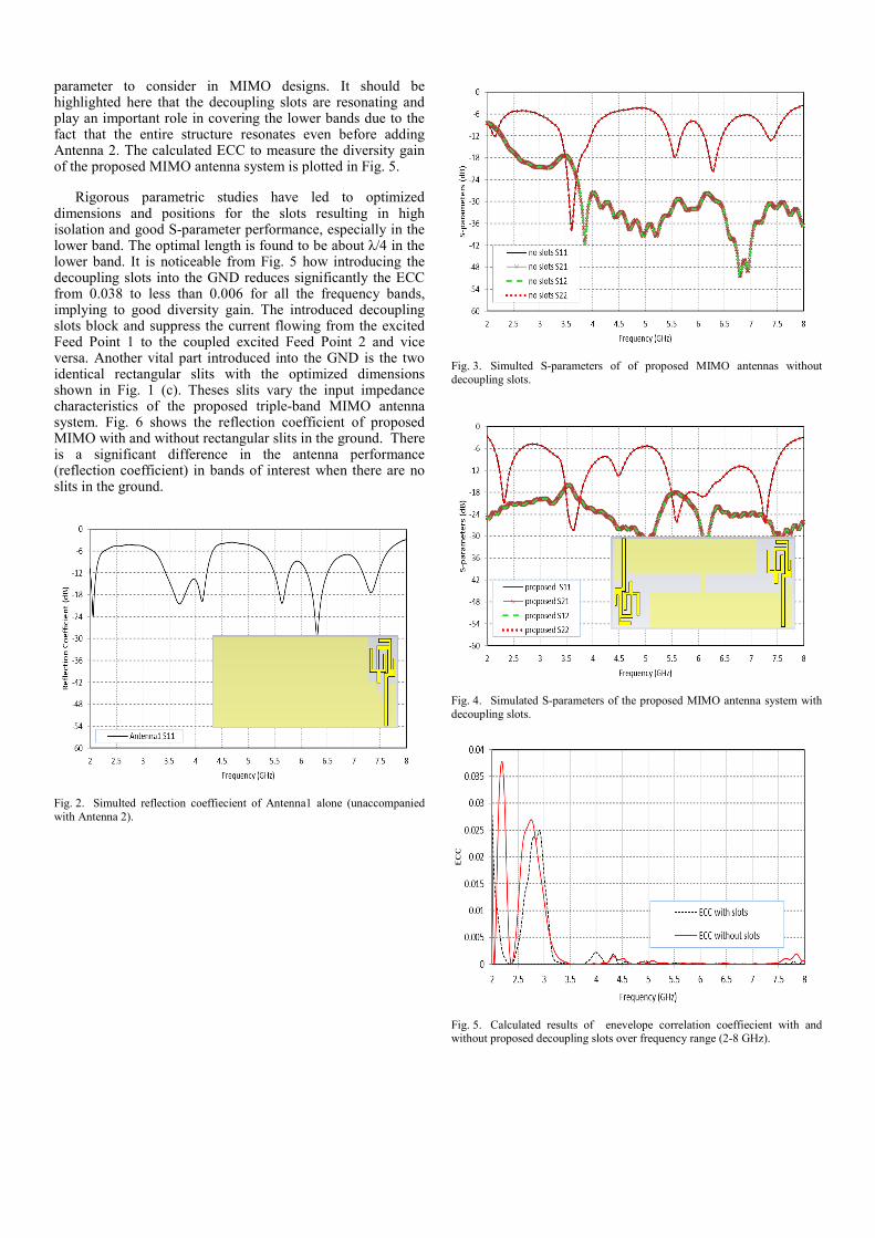
parameter to consider in MIMO designs. It should be highlighted here that the decoupling slots are resonating and play an important role in covering the lower bands due to the fact that the entire structure resonates even before adding Antenna 2. The calculated ECC to measure the diversity gain of the proposed MIMO antenna system is plotted in Fig. 5.
Rigorous parametric studies have led to optimized dimensions and positions for the slots resulting in high isolation and good S-parameter performance, especially in the lower band. The optimal length is found to be about λ/4 in the lower band. It is noticeable from Fig. 5 how introducing the decoupling slots into the GND reduces significantly the ECC from 0.038 to less than 0.006 for all the frequency bands, implying to good diversity gain. The introduced decoupling slots block and suppress the current flowing from the excited Feed Point 1 to the coupled excited Feed Point 2 and vice versa. Another vital part introduced into the GND is the two identical rectangular slits with the optimized dimensions shown in Fig. 1 (c). Theses slits vary the input impedance characteristics of the proposed triple-band MIMO antenna system. Fig. 6 shows the reflection coefficient of proposed MIMO with and without rectangular slits in the ground. There is a significant difference in the antenna performance (reflection coefficient) in bands of interest when there are no slits in the ground.
Fig. 2. Simulted reflection coeffiecient of Antenna1 alone (unaccompanied with Antenna 2).
Fig. 3. Simulted S-parameters of of proposed MIMO antennas without decoupling slots.
Fig. 4. Simulated S-parameters of the proposed MIMO antenna system with decoupling slots.
Fig. 5. Calculated results of enevelope correlation coeffiecient with and without proposed decoupling slots over frequency range (2-8 GHz).

Fig. 6. Simulated reflection coefficient of proposed MIMO antenna with and without rectangular slits in the ground.
The simulated and measured S11 and S21 results given in Fig. 7 show good agreement. Small differences in the results could be attributed to fabrication tolerances and proximity of the feeding coaxial cables. The S11 is better than -6dB and S21 better than -18dB across the required frequency bands. Surface current distributions of the proposed system at different resonant frequencies are given in Fig. 8. When Antenna 1 is excited, Antenna 2 is terminated with matched load. As seen in Fig. 8 (a), (b), and (c), different parts of the meander monopole are responsible for resonance at specific frequencies. The proposed decoupling slots create additional electrical paths for the current to flow and also constrict the current flow from one antenna to the other.
The proposed MIMO antenna system simulated efficiency is presented in Fig. 9. Over the frequency bands under consideration, both antenna’s radiation efficiencies are better than 85%. In general, handset antennas tend to have much lower efficiencies due to small size of the radiating elements. Fig. 10 shows the radiation characteristics of the proposed MIMO antenna system at 2.3, 3.6 and 5.6 GHz respectively. The antenna system exhibits omnidirectional radiation characteristics at 2.3 GHz and more variations in the radiation patterns are observed at the higher frequencies, 3.6 and 5.6 GHz.
Fig. 7. Simulated and measured S11 and S21 of proposed MIMO antenna system.
(a) (b) (c)
Fig. 8. Surface current distributions of the proposed MIMO antenna system for Antenna 1 at (a) 2.3, (b) 3.6, and (c) 5.6 GHz.
Fig. 9. Radiated antenna effeciency for proposed MIMO antennas system.

Fig. 10. Radiated characterstics of the proposed MIMO antenna system at (a) 2.3, (b) 3.6, and (c) 5.6 GHz.
IV. CONCLUSION This article has proposed a novel MIMO antenna system with an optimised decoupling technique for isolation better than 18 dB across all the operating bands. The system consists of two planar printed compact monopole antennas with decoupling slots in the ground plane to accomplish ECC below 0.006 over the operating bands. Antenna performances with and without the proposed decoupling slots have been presented. The proposed design covers the following standard operating bands in the frequency range 2-8 GHz: LTE2300 (2305-2400 MHz), WLAN2400 (2400-2484 MHz), WiMAX3500 (3300-3700 MHz), and WLAN/WiMAX/HIPERLAN5200/5800 for smart phones (return loss better than 6 dB). The radiation patterns and efficiencies of the design make it a potential candidate for mobile device applications. The simulation and
measurement results of the proposed design illustrate the good performance of the MIMO antenna system. The presented decoupling design can be applied to different multiple antenna or MIMO systems.
REFERENCES [1] Y. Choukiker, S. Sharma, and S. Behera, “Hybrid fracatal shape planar
monopole antenna covering multiband wireless communications with MIMO implementation for handheld mobile devices,” IEEE Trans. Antennas Propag., Vol. 62, No. 3, pp. 1483-1488, March. 2014.
[2] S. Shoaib, I. shoaib,N. Shoaib, X. Chen, and C. Parini, “MIMO antenna for mobile handsets,” IEEE Trans. Antennas Wireless Propag Letters., Vol. X, No. X, DOI 10.1109/LAWP.2014.2385593, 2015.
[3] W. Kin-Lu, K. Ting-Wei, and Tu. Ming-Fang, “Internal mobile phone antenna array for LTE/WWAN and LTE MIMO operations,” Microwave and Opt Tech Letters., Vol. 53, No. 7, July 2011.
[4] M. A. Jensen, and J.W. Wallace, “A review of antennas and propagation for MIMO wireless communications,” IEEE Trans. Antennas Propag., Vol. 52, No. 11, pp. 2810-2824, Nov. 2004.
[5] E. K Antonino-Daviu, M. Cabedo-Fabres, B. Bernardo-Clemente, and M. Ferrando-Bataller, “Printed multimode antenna for MIMO systems,” J. of Electromagn. Waves and Appl., Vol. 25, pp. 2022-2032, March, 2011.
[6] O. A. Saraereh, C. J. Panagamuwa, and J. C. Vardaxoglu, “Low Correlation Multiple Antenna System for Mobile Phone Applications Using Novel Decoupling Slots in Ground Plane,” Loughborough Antennas and Propagation Conference (LAPC), pp. 577 – 581, Nov. 2013.
[7] Y. Ban, Zhong. Chen, Zhi. Chen, K. Kang, and J. Li, “Decoupled hepta-band antenna array for WWAN/LTE smartphone applications,” IEEE Trans. Antennas Wireless Propag Letters, Vol. 13, pp. 999-1002, 2014.
[8] S. Cui, S. X. Gong, Y. Liu, W. Jiang, and Y. Gaun, “Compact and low coupled monopole antennas for MIMO system applications,” J. of Electromagn. Waves and Appl., Vol. 25, 703-712, March, 2011.
[9] J. Jasper Sweetlin, and T. Anita Jones Mary, “Mutual decoupling in quad band MIMO slotted PIFA for wireless applications,” Int J. of Engineering and Science., Vol. 1, No. 2, pp. 303-307, 2012.
[10] S. Lai, Y. Li, and Chia. Tang, “A MIMO LTE antenna system with decoupling elements for smart phone application,” Proceedings of ISAP., pp. 595-596, Dec, 2014.
[11] K. Wong, and J. Lu, “3.6-GHz 10-Antenna array for MIMO operation in the smartphone,” Microwave and Opt Tech Letters.,Vol. 57, No. 7, pp. 1699-1704, July 2015.
[12] L. Yang, and T. Li, “Box-folded foure-element MIMO antenna system for LTE handsets,” Electronics Letters.,Vol. 51, No. 6, pp. 440-441, March 2015.
[13] S. Wang, and Z. Du, “Decoupled dual-antenna system using crossed neutralization lines for LTE/WWAN smartphone applications,” IEEE Trans. Antennas and Wireless Propag Letters., Vol. 14, pp. 523-526, 2015.
[14] H. Singh, G. Pandey, P. Bharti, and M. Meshram, “A low profile tri-band diversity antenna for WLAN/Wimax/HIPERLAN,” Microwave and Opt Tech Letters.,Vol. 57, No. 2, pp. 452-457, February. 2015.
[15] I. Elfergani1, A. Hussaini, J. Rodriguez, Raed A. Abd-Alhameed, C. See, N. Jan, S. Zhu, N. McEwan, “Compact and closely spaced tunable printed F-slot multiple-input–multiple-output antenna system for portable wireless applications with efficient diversity,” IET Sci. Meas. Technol., Vol. 8, No. 6, pp. 359–369, doi: 10.1049/iet-smt.2013.0276., 2014.
[16] J. Han Yoon, Y. Rhee, and Y. Kil Jang, “ Compact monopole antenna design for WLAN/WiMAX triple band operations,” Microwave and Opt Tech Letters.,Vol. 54, No. 8, pp. 1838-1846, August. 2012.
(a)
(b)
(c)


![Mimo and Smart Antennas for 3g and 4g Wireless Systems May 2010 Final[1]](https://static.fdocuments.in/doc/165x107/546095e9b1af9f09598b5453/mimo-and-smart-antennas-for-3g-and-4g-wireless-systems-may-2010-final1.jpg)
