A Microfacet-Based Shadowing Function to Solve the Bump ...A Microfacet-Based Shadowing Function to...
7
A Microfacet-Based Shadowing Function to Solve the Bump Terminator Problem Alejandro Conty Estevez, † Pascal Lecocq, † and Clifford Stein † † Sony Pictures Imageworks Abstract We present a technique to hide the abrupt shadow terminator line when strong bump or normal maps are used to emulate micro-geometry. Our approach, based on microfacet shadowing functions, is simple and inexpensive. Instead of rendering detailed and expensive height-field shadows we apply a statistical solution built on the assumption that normals follow a nearly normal random distribution. We also contribute a useful approximate variance measure for GGX, which is otherwise undefined analytically. 1 Introduction Figure 1: A comparison of a cloth model with strong bump mapping. The raw result (left) shows a sudden light drop at the terminator, while our shadowing technique (right) replaces it with a more natural and visually pleasing smooth gradient. Bump mapping is widely used both in real-time rendering for games and in batch rendering for cinema. It adds high frequency detail on surfaces that would otherwise be too expensive to render with actual geometry or displacement mapping. It is responsible for those last fine- grained detailed imperfections added to surfaces. It works as a perturbation in the normal’s orientation that does not derive from the under- lying geometry but instead from a texture map or some procedural pattern. But like any other shortcut, it can yield unwanted artifacts—specifically the well-known hard terminator shown in Figure 1. This occurs because the expected smooth intensity falloff due to the changing normal is interrupted when the surface suddenly shadows the incident light rays. This problem does not appear when the normal has no perturbation since the irradiance has already dropped to zero by the time this happens. But bump mapping has the effect of extending the light’s influence too far by tilting normals toward the incoming light direction, making the lit area cross the shadow terminator. We solve this problem by applying a shadowing function inspired by microfacet theory. Bump mapping can be thought of as a large-scale normal distribution, and by making assump- tions on its properties we can use the same shadowing as in the widely used GGX microfacet distribution. Even though these assumptions will be wrong in many cases, the shadow term still works in practice, even when the bump or normal map exhibits non-random structure. 1
Transcript of A Microfacet-Based Shadowing Function to Solve the Bump ...A Microfacet-Based Shadowing Function to...

A Microfacet-Based Shadowing Function to Solvethe Bump Terminator Problem
Alejandro Conty Estevez,† Pascal Lecocq,† and Clifford Stein†
†Sony Pictures Imageworks
Abstract
We present a technique to hide the abrupt shadow terminator line when strong bump or normalmaps are used to emulate micro-geometry. Our approach, based on microfacet shadowingfunctions, is simple and inexpensive. Instead of rendering detailed and expensive height-fieldshadows we apply a statistical solution built on the assumption that normals follow a nearlynormal random distribution. We also contribute a useful approximate variance measure forGGX, which is otherwise undefined analytically.
1 Introduction
Figure 1: A comparison of a cloth model with strong bump mapping. The raw result (left) shows asudden light drop at the terminator, while our shadowing technique (right) replaces it witha more natural and visually pleasing smooth gradient.
Bump mapping is widely used both in real-time rendering for games and in batch renderingfor cinema. It adds high frequency detail on surfaces that would otherwise be too expensiveto render with actual geometry or displacement mapping. It is responsible for those last fine-grained detailed imperfections added to surfaces.
It works as a perturbation in the normal’s orientation that does not derive from the under-lying geometry but instead from a texture map or some procedural pattern. But like any othershortcut, it can yield unwanted artifacts—specifically the well-known hard terminator shownin Figure 1.
This occurs because the expected smooth intensity falloff due to the changing normal isinterrupted when the surface suddenly shadows the incident light rays. This problem does notappear when the normal has no perturbation since the irradiance has already dropped to zeroby the time this happens. But bump mapping has the effect of extending the light’s influencetoo far by tilting normals toward the incoming light direction, making the lit area cross theshadow terminator.
We solve this problem by applying a shadowing function inspired by microfacet theory.Bump mapping can be thought of as a large-scale normal distribution, and by making assump-tions on its properties we can use the same shadowing as in the widely used GGX microfacetdistribution. Even though these assumptions will be wrong in many cases, the shadow termstill works in practice, even when the bump or normal map exhibits non-random structure.
1

2 Previous Work
To our knowledge, no specific solution to this terminator problem has been published. Thereis related work from Max [5] to compute the bump-to-bump detailed shadows in close-ups,which is based on finding the horizon elevation on a per-point basis. It was extended for curvedsurfaces by Onoue et al. [7]. But these methods, though accurate for point-to-point shadows,require auxiliary tables and more lookups. They are not ideal for high-frequency bump mappingwhere the terminator line, and not detailed shadows, is the only concern.
Nevertheless, the terminator problem is an issue in almost every render engine and theoffered solution is often to just moderate the height of the bump or resort to displacement. Oursolution is fast, simple, and does not require any additional data or pre-computation.
On the other hand, microfacet theory and its shadowing term has been studied extensivelyby Heitz [4], Walter et al. [8], and others ever since it was introduced by Cook and Torrance [2].We draw inspiration from their work to derive a plausible solution to the artifacts discussed inthis document.
3 Method
The cause of the problem is that distorting the normal alters the natural cosine falloff of the lightirradiance, making the lit area advance too far into the shadowed side. Since the surface thatthe map simulates is only imaginary, the renderer is unaware of any height-field shadowing andtherefore the light vanishes suddenly, as shown in Figure 2. These defects, although expected,can be distracting and give an unwanted toon appearance. Artists expect this transition fromlight to shadow to be smooth.
Figure 2: The insets show the type of terminator artifacts seen with strong bump mapping.
In Figure 3 we show how the bumped normals simulating a surface that does not existbring bright areas too close to the terminator. This occurs because the shadowing factor(illustrated in the drawing) is completely ignored. In microfacet theory this factor is called theshadowing/masking term, which is a value in the [0, 1] interval that is computed from both thelight and viewing directions for maintaining reciprocity of the BSDF.
We also use the Smith shadowing approach for bump mapping. It scales down scatteredenergy arriving from grazing angles only, which on the terminator will gracefully darken andblend the lit and dark areas without altering the rest of the look. Its derivation requires knowingthe normal distribution, which is unknown for an arbitrary bump or normal map but we willmake the assumption that it is random and normally distributed. This is almost never true,but for shadowing purposes we will show that it works well.
2

Smooth Normals
Bumped Normals
Lig
ht S
ource
Ignored Shadowing
Figure 3: In the upper half of the sphere, smooth normals following the actual surface pose no problemfor the terminator. But the lower half introduces a distortion that might tilt normals towardthe light source, creating bright areas too close to where the light is completely occluded.These come from ignoring the shadowing that such an imaginary surface would receive.
3.1 The Normal Distribution
We chose the GGX distribution for its simplicity and efficient implementation. Like mostdistributions, it has one roughness parameter α which modulates the spread of the microfacetslopes. A subtle bump effect will correspond to low roughness α and vice versa for a strongbump. The main unknown is how to find this α parameter.
We ruled out computing this property from the texture maps. Sometimes they are procedu-ral and unpredictable, and we wanted to avoid any pre-computation pass. The idea is to guessα from the bumped normal we receive at lighting time without extra information. That is, ourguess is computed locally without information from neighboring points.
Surf
ace n
orm
al
Bum
p n
orm
al
Figure 4: Based on the bumped normal divergence, we imagine a normal distribution where the tangentis located in the extreme, at two standard deviations. This places 94% of the other bumpednormals closer to the actual surface orientation.
We look at the tangent of the divergence angle that the bumped normal forms with the realsurface normal. For computing a shadowing term that covers this normal with a reasonableprobability, as shown in Figure 4, we equate this tangent to two standard deviations of a normaldistribution. Then we can replace this with GGX and apply the well-known shadowing term
G1 =2
1 +√
1 + α2 tan2 θi, (1)
where θi is the incoming light direction angle with the real surface normal.But this raises the question: how to compute GGX’s α from the distribution variance? GGX
is based on the Cauchy distribution, which has an undefined mean and variance. It was found
3

numerically in Conty et al. [1] that if the long tails are ignored to preserve the majority of thedistribution mass, σ2 = 2α2 is a good approximation of GGX’s variance. Therefore we use
αggx =
√tan2 θd
8, (2)
but clamping the result to [0, 1]. This measure reflects the fact that GGX shows an appar-ent roughness higher than Beckmann, whose tangent variance is α2. By this relationship theequivalence is roughly αbeck '
√2 αggx.
We validated our GGX’s variance approximation by running a comprehensive visual studyon a GGX surface perturbed with a broad range of bump normal distributions. We used afiltered antialiased normal technique from Olano et al. and Dupy et al. [6, 3] that encodes thefirst and second moment of the bump slope distribution in a mipmapped texture. For each pixel,we estimate the variance of the normal distribution by fetching the selected filtered mipmaplevel for that pixel and expanding the GGX roughness accordingly. We compared our GGXvariance relationship with a naive Beckmann variance mapping and with a reference by raytracing non-filtered bump normals at a high sampling rate. In all scenarios, our mapping showsbetter preservation of the perceived GGX roughness induced by the bump normal distribution,as shown in Figure 5.
Figure 5: Roughness expansion of a GGX material according to a filtered antialiased normal distri-bution using a common Beckmann variance mapping (top) and using our GGX’s varianceapproximation (bottom), both compared to a non-filtered reference (middle). In this testcase, the GGX base surface roughness is varying from 0.01 (left) to 0.8 (right) and showsthat our approximation better preserves the overall perceived roughness induced by the un-derlying normal distributions.
3.2 The Shadowing Function
In a typical microfacet BSDF, the shadowing/masking term is computed for both light andviewing directions to preserve reciprocity. In our implementation, we are applying our bumpshadowing only to the light direction to preserve the original look as much as possible, therefore
4
−5 −4 −3 −2 −1 0 1 2 3 4 5
slopeG
GX
den
sity
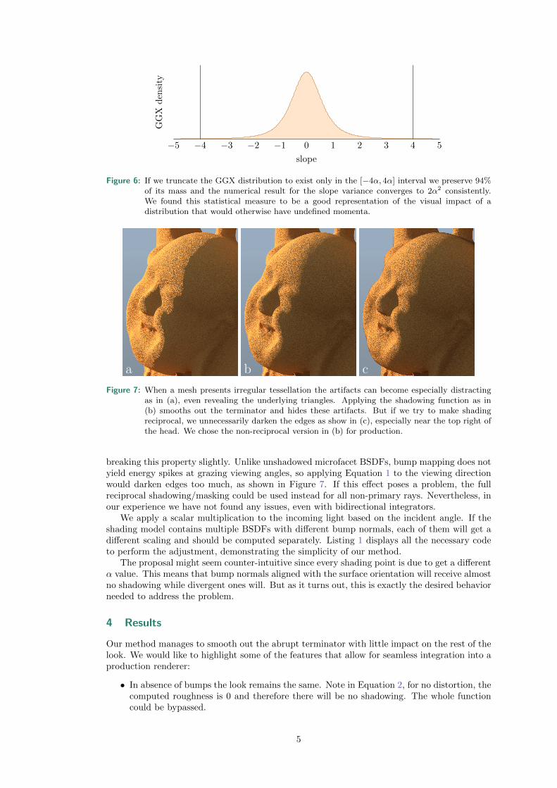
Figure 6: If we truncate the GGX distribution to exist only in the [−4α, 4α] interval we preserve 94%of its mass and the numerical result for the slope variance converges to 2α2 consistently.We found this statistical measure to be a good representation of the visual impact of adistribution that would otherwise have undefined momenta.
a b c
Figure 7: When a mesh presents irregular tessellation the artifacts can become especially distractingas in (a), even revealing the underlying triangles. Applying the shadowing function as in(b) smooths out the terminator and hides these artifacts. But if we try to make shadingreciprocal, we unnecessarily darken the edges as show in (c), especially near the top right ofthe head. We chose the non-reciprocal version in (b) for production.
breaking this property slightly. Unlike unshadowed microfacet BSDFs, bump mapping does notyield energy spikes at grazing viewing angles, so applying Equation 1 to the viewing directionwould darken edges too much, as shown in Figure 7. If this effect poses a problem, the fullreciprocal shadowing/masking could be used instead for all non-primary rays. Nevertheless, inour experience we have not found any issues, even with bidirectional integrators.
We apply a scalar multiplication to the incoming light based on the incident angle. If theshading model contains multiple BSDFs with different bump normals, each of them will get adifferent scaling and should be computed separately. Listing 1 displays all the necessary codeto perform the adjustment, demonstrating the simplicity of our method.
The proposal might seem counter-intuitive since every shading point is due to get a differentα value. This means that bump normals aligned with the surface orientation will receive almostno shadowing while divergent ones will. But as it turns out, this is exactly the desired behaviorneeded to address the problem.
4 Results
Our method manages to smooth out the abrupt terminator with little impact on the rest of thelook. We would like to highlight some of the features that allow for seamless integration into aproduction renderer:
• In absence of bumps the look remains the same. Note in Equation 2, for no distortion, thecomputed roughness is 0 and therefore there will be no shadowing. The whole functioncould be bypassed.
5

1 // Return alpha^2 parameter from normal divergence2 float bump_alpha2(float3 N, float3 Nbump)3 {4 float cos_d = min(fabsf(dot(N, Nbump)), 1.0f);5 float tan2_d = (1 - cos_d * cos_d) / (cos_d * cos_d);6 return clamp (0.125f * tan2_d , 0.0f, 1.0f);7 }8
9 // Shadowing factor10 float bump_shadowing_function(float3 N, float3 Ld , float alpha2)11 {12 float cos_i = max(fabsf(dot(N, Ld)), 1e-6f);13 float tan2_i = (1 - cos_i * cos_i) / (cos_i * cos_i);14 return 2.0f / (1 + sqrtf(1 + alpha2 * tan2_i));15 }16 \label{code}
Listing 1: These two functions suffice to implement the terminator fix. The second one can be used asa multiplier for either the incoming light or the BSDF evaluation.
Figure 8: From left to right, a structured fabric bump pattern, with increasing bump amplitude. Thetop row shows the uncorrected bump render result, and the bottom row demonstrates ourshadowed version with the smooth terminator.
• Subtle bumps will cause imperceptible changes because of the low estimated α. This casedoes not suffer from artifacts and does not need to be fixed.
• Only grazing light directions are affected by the shadowing function. As is typical withmicrofacet models, incident light at angles that more directly face the surface will beunaffected.
Though our derivations are based on a normal distribution disconnected from reality, we showthat it gives plausible results for structured patterns, as illustrated in Figure 8. With lowbump amplitudes in the left column, our shadowing term only minimally changes an imagethat requires no correction. As the terminator becomes more prominent, our technique behavesmore strongly and smooths out the transition region. This method is especially helpful forstrong bumps.
5 Acknowledgments
This work was developed within the core development of the Arnold renderer at Sony PicturesImageworks with Christopher Kulla and Larry Gritz.
6

References
[1] Conty Estevez, A., and Lecocq, P. Fast Product Importance Sampling of EnvironmentMaps. In ACM SIGGRAPH 2018 Talks (2018), pp. 69:1–69:2.
[2] Cook, R. L., and Torrance, K. E. A Reflectance Model for Computer Graphics. ACMTransactions on Graphics 1, 1 (Jan. 1982), 7–24.
[3] Dupuy, J., Heitz, E., Iehl, J.-C., Pierre, P., Neyret, F., and Ostromoukhov, V.Linear Efficient Antialiased Displacement and Reflectance Mapping. ACM Transactions onGraphics 32, 6 (Sept. 2013), 211:1–211:11.
[4] Heitz, E. Understanding the Masking-Shadowing Function in Microfacet-Based BRDFs.Journal of Computer Graphics Techniques 3, 2 (June 2014), 48–107.
[5] Max, N. L. Horizon Mapping: Shadows for Bump-Mapped Surfaces. The Visual Computer4, 2 (Mar 1988), 109–117.
[6] Olano, M., and Baker, D. Lean Mapping. In Symposium on Interactive 3D Graphicsand Games (2010), pp. 181–188.
[7] Onoue, K., Max, N., and Nishita, T. Real-Time Rendering of Bumpmap ShadowsTaking Account of Surface Curvature. In International Conference on Cyberworlds (Nov2004), pp. 312–318.
[8] Walter, B., Marschner, S. R., Li, H., and Torrance, K. E. Microfacet Modelsfor Refraction Through Rough Surfaces. In Eurographics Symposium on Rendering (2007),pp. 195–206.
7

![Microfacet Model and Material Appearancesungeui/GCG/Student_Presentations/... · SIGGRAPH 2016 [2] A Two-Scale Microfacet Reflectance Model Combining Reflection and Diffraction Nicolas](https://static.fdocuments.in/doc/165x107/5fbc86ce93f25735ea42c0e4/microfacet-model-and-material-appearance-sungeuigcgstudentpresentations.jpg)