A methodology to determine the LCI of steel industry co ...167ec6bc-d974-4405-8d53... · A...
38
1 A methodology to determine the LCI of steel industry co-products 14 th February 2014 Contents Introduction.............................................................................................................................................. 3 1. Motivation ................................................................................................................................... 4 2. Justification for the methodology of multifunctional systems ..................................................... 5 2.1. The ISO standard definition for multifunctional systems ....................................................... 5 2.2. The current worldsteel methodology: system expansion ...................................................... 6 2.3. Proposed method: sub-division by physical partitioning ........................................................ 7 2.4. Choice of allocation method (i.e. economic allocation vs sub-division by physical partitioning) .......................................................................................................................................... 8 2.5. Treatment of process gases .................................................................................................. 9 3. Relevant flows .......................................................................................................................... 10 4. Mathematical model of the blast furnace ................................................................................. 11 5. Partitioning procedures by process unit ................................................................................... 11 5.1. Partitioning rules .................................................................................................................. 12 5.1.1. Energy-based .................................................................................................................. 12 5.1.1.1. Energy-based partitioning for the BF .......................................................................... 13 5.1.1.2. Energy-based partitioning for the BOF ....................................................................... 18 5.1.2. Ferrous content ............................................................................................................... 19 5.1.3. 100% slag ........................................................................................................................ 20 5.1.4. Hot metal purity ............................................................................................................... 20 5.1.5. 100% hot metal................................................................................................................ 21 5.1.6. 100% crude steel ............................................................................................................. 21 5.1.7. System expansion for process gases ............................................................................. 21 5.2. Coke ovens .......................................................................................................................... 21 5.3. Sinter and pellet plant .......................................................................................................... 22 5.4. Blast Furnace ....................................................................................................................... 22 5.5. Basic Oxygen Furnace (BOF).............................................................................................. 24
-
Upload
hoangduong -
Category
Documents
-
view
216 -
download
2
Transcript of A methodology to determine the LCI of steel industry co ...167ec6bc-d974-4405-8d53... · A...
1
A methodology to determine the LCI of steel industry co-products
14th February 2014
Contents
Introduction.............................................................................................................................................. 3
1. Motivation ................................................................................................................................... 4
2. Justification for the methodology of multifunctional systems ..................................................... 5
2.1. The ISO standard definition for multifunctional systems ....................................................... 5
2.2. The current worldsteel methodology: system expansion ...................................................... 6
2.3. Proposed method: sub-division by physical partitioning ........................................................ 7
2.4. Choice of allocation method (i.e. economic allocation vs sub-division by physical partitioning) .......................................................................................................................................... 8
2.5. Treatment of process gases .................................................................................................. 9
3. Relevant flows .......................................................................................................................... 10
4. Mathematical model of the blast furnace ................................................................................. 11
5. Partitioning procedures by process unit ................................................................................... 11
5.1. Partitioning rules .................................................................................................................. 12
5.1.1. Energy-based .................................................................................................................. 12
5.1.1.1. Energy-based partitioning for the BF .......................................................................... 13
5.1.1.2. Energy-based partitioning for the BOF ....................................................................... 18
5.1.2. Ferrous content ............................................................................................................... 19
5.1.3. 100% slag ........................................................................................................................ 20
5.1.4. Hot metal purity ............................................................................................................... 20
5.1.5. 100% hot metal................................................................................................................ 21
5.1.6. 100% crude steel ............................................................................................................. 21
5.1.7. System expansion for process gases ............................................................................. 21
5.2. Coke ovens .......................................................................................................................... 21
5.3. Sinter and pellet plant .......................................................................................................... 22
5.4. Blast Furnace ....................................................................................................................... 22
5.5. Basic Oxygen Furnace (BOF).............................................................................................. 24

2
5.6. Hot Rolling ........................................................................................................................... 24
5.7. Electric Arc Furnace (EAF) and the Stainless Steel EAF .................................................... 24
6. Implementation ......................................................................................................................... 25
7. Results of methodology to be incorporated ............................................................................. 25
8. Sensitivity Analysis ................................................................................................................... 31
9. Critical Review ......................................................................................................................... 32
Appendix 1: Operation of a Blast Furnace ............................................................................................ 33
Appendix 2: Overview of the BOF steelmaking process ....................................................................... 36
Appendix 3: List of allocation rules applied to specific inputs and output flows in steelmaking processes .............................................................................................................................................. 37

3
INTRODUCTION
This methodology is NOT the position of the World Steel Association or EUROFER. Following the EUROFER IPP Project that was completed in 2007, a final report was produced and is available on the EUROFER website. Part of this project included developing a method for how to calculate the LCI for slags produced in the steel making processes. This method has since been further developed by the steel industry in order to provide a methodology to determine the LCI for steel slags and is also available to be used when system expansion (the current worldsteel approach to dealing with multi-functional systems) is not possible. This methodology is not mandatory but has been reviewed to be in line with the ISO 14044: 2006 and EN 15804 standards. The worldsteel methodology remains as outlined in the worldsteel methodology report, 2011.
In the process of steel making, a number of co-products are produced that are then sold on to other industries. These co-products include slags, process gases, benzene and tar etc. (see table 2), which have a valuable economic and industrial use and, are used either on site or are sold to be used directly or further processed off site, and are not considered as wastes. Within ISO 14040: 2006, co-products are defined as “any of two or more products coming from the same unit process or product system”. In other legislative and subject fields, such as the Waste Framework Directive, co-products are alternatively referred to as by-products. These co-products are beneficial to society and often have significant environmental benefits as the use of them results in less virgin materials being consumed.
A prime example is the use of blast furnace slag by the cement and concrete industry. Blast furnace slag can be used as a substitute for Portland cement clinker in the cement manufacturing process and thereby reduces the cement industry’s need to produce clinker from limestone, which subsequently also reduces their CO2 emissions. Ground and granulated blast furnace slag (GGBS) is also used as a direct replacement of Portland cement in ready mixed concrete. Typically 1 tonne of slag replaces between 0.9 and 1 tonne of primary clinker or cement
1. The following is a summary of the main
benefits of using blast furnace slag2,3
which helps define the material as a co-product and not a waste:
In terms of strength, the utilisation of blast furnace slag can match or even outperform that of traditional primary materials
Longer setting times reduces the risk of concrete cracking due to overheating
No requirements for calcination, and subsequent CO2 emissions, in the cement factory
Lower capital costs
Overall reduction of the carbon footprint and environmental burden due to avoidance of virgin clinker use
Provides concrete with increased resistance to sulphate chemical attack, making it especially suitable for use in marine environments
Whiter colour is aesthetically desirable compared to grey Portland cement
All co-produced or recovered materials carry an environmental burden. The substituted primary material provides no further indication about the magnitude of the environmental burdens carried other than practically a maximum cap. However, it would seem appropriate for recovered materials to carry a lower burden than the primary material substituted. For example, burdens for the granulated slag from the blast furnace should be lower than the burdens of clinker or cement that it substitutes.
1 The value of 0.9 comes from AFNOR P 18-305. In the UK, 1 tonne GGBS typically replaces 1 tonne of Portland cement. The worldsteel methodology uses the conservative value of 0.9. 2 http://www.ukcsma.co.uk/uses-of-ggbs.html
3 http://www.euroslag.com/applications/

4
This paper states the rules by which environmental burdens and credits of steel making are partitioned between products and co-products, in order to be able to calculate the environmental impacts of using co-products in other industries.
1. MOTIVATION
The worldsteel LCA methodology currently uses system expansion to account for the fact that co-products are produced during the steel making process. The steel making ‘system’ is expanded to incorporate those processes which use the co-products from the steel making process and which therefore avoid the alternative production using primary materials. This ‘maximum’/whole credit that is associated with the avoidance of primary production of materials is then incorporated within the steel LCI. The steel industry believes that system expansion is the most appropriate method to calculate for the products produced in the steel making process, as it is a true reflection of the changes to environmental flows that result from the production and subsequent use of these co-products.
Ideally two different industries, especially when exchanging recovered materials, should use compatible calculation rules; however the LCA methodological assumptions are driven by the goal of the study and may differ in two different studies performed in different contexts. For an LCA of construction materials, products from different industries can be mixed together, as is the case of reinforced concrete using steel rebar. For example, within the worldsteel methodology where system expansion is used, a credit is applied to the steel LCI for the amount of blast furnace slag, which can be used as a replacement for virgin cement clinker in cement manufacture, or virgin cement directly in concrete manufacture, as well as other uses such as for road-stone, embankment or as a fertiliser. The avoided environmental burden will vary for each application of the slag, depending on the alternative production options. However, in most existing LCAs, no burden is specifically given to those industries using the steel industry co-products, i.e. the slag, who therefore effectively take them as being environmentally burden-free. This leads to a mismatch in accounting the benefits of slag recycling between the steel plant and the cement plant. . To accurately assess the environmental impact of the use of these materials, and their use in the production of other products, a suitable burden should be given to them, in line with the credit that would subsequently be given to the steel product.
In this case, consistency as well as the avoidance of double counting should be sought in the different LCA studies and methodologies considered. Hence, instead of system expansion, internal process sub-division or allocation is necessary. Furthermore, there are a number of other standards that have been developed which either requires an LCI for specific products including slag, or which the worldsteel methodology is not consistent with. A couple of examples are:
The European Commission’s European Life Cycle Reference Data (ELCD) System http://lca.jrc.eu.europa.eu/. There is a requirement to have LCI data available for all materials. Steel LCI data is already provided on the database, but data for the other co-products are not yet available.
EN 158044 advocates the modularity principle, where the environmental influence of processes is
assigned to the module in the life cycle where they occur. The specified methods for sub-dividing, else - where the latter not possible - allocating the burden between the co-products are based on the inherent properties of the physical flows, physical relationships or economic value.
Co-product specific LCIs are therefore required and this document sets out the way in which the European steel industry determines such an LCI for both the steel that is produced as well as the other co-products, based on known physical relationships. A number of different rules have been incorporated within the final methodology. The rules were analysed with respect to their justification and to ensure that a realistic and justifiable methodology was developed. The impact of the changes in the results, in comparison to the previous methodology, was determined for verification and plausibility purposes and as a cross-check of the applied rules.
4 EN 15804 s 6.4.3.1. and 6.4.3.2

5
The incorporation of this methodology within the steel making LCI data focuses only on the steel industry’s own flows and does not include the non-steel-related flows which are associated with the avoided production of other materials (e.g. clinker) and which are included in the system expansion approach. It will also result in less distortion when comparing materials, as the actual environmental impact will be associated with the materials produced. Due to the system expansion rule (obtaining credits for the avoided production of a material), LCI flows appeared within the steelmaking LCI which are never actually part of an original steel life cycle or unexpected or negative values for certain materials (for example natural aggregate, lignite, limestone or soil) could also be present which are related to the avoided production of the replaced material. This can cause confusion for those using the datasheets. Utilising this new methodology will avoid such perceived abnormalities within the datasets, as the overall LCI is partitioned between the different co-products.
For applications where a co-product LCI is required, the co-product calculation method presented in this report can be applied. The method was developed in co-operation with steel industry experts, understanding the technicalities of the steel-making process as well as LCA methodologies.
2. JUSTIFICATION FOR THE METHODOLOGY OF MULTIFUNCTIONAL SYSTEMS
2.1. The ISO standard definition for multifunctional systems
In cases such as the integrated steel making process (namely the blast furnace and the basic oxygen furnace) where a process has more than one product, the allocation procedure , treatment of a multi-functional system, must be applied in accordance with ISO 14044:2006
5, and should follow this three
step approach:
In general, allocation approaches are applied in cases where real multi-functional systems have to be modelled into one or several mono-functional systems, where the two sub-points of Step 1 are not applicable, see Figure 2-1. The aim is to partition or allocate the steel plant inventory between the different main co-products (e.g. steel, blast furnace slag etc.).
5 ISO 14044: 2006
Step 1: Wherever possible allocation should be avoided by:
dividing the unit process to be allocated into two or more sub-processes and collecting the input and output data related to these sub-processes, or
expanding the product system to include the additional functions related to the co-products
Step 2: Where allocation cannot be avoided, the inputs and outputs of the system should be partitioned between its different products or functions in a way that reflects the underlying physical relationships between them; i.e. they should reflect the way in which the inputs and outputs are changed by quantitative changes in the products or functions delivered by the system.
Step 3: Where physical relationship alone cannot be established or used as the basis for allocation, the inputs should be allocated between the products and functions in a way that reflects other relationships between them. For example, input and output data might be allocated between co-products in proportion to the economic value of the products.

6
Figure 2-1: Multi-functional system with different main and co-products
2.2. The current worldsteel methodology: system expansion
The current worldsteel Life Cycle Inventory Methodology Report 2011, details the data collection procedure and LCI methodology used for steel products. It also describes how co-products are handled (section 4.1.1 on system expansion) and how the approach of system expansion is used to avoid allocation. System expansion is an allocation procedure, in compliance with ISO 14044:2006 (see step 1 above) based on the fact that the co-product saves another product with equivalent function (e.g. blast furnace slag saves clinker production). The expanded system will then include the route of the product(s) replaced by the co-product. Figure 2-2 shows this method in detail below.
Figure 2-2: Multi-functional system, system expansion
Steel product(s) = main product(s)
Co-product(s) of steel
production route
Credit systems for co-product(s) of steel production route
Co-product Resources
Credit system = Inverted Production:
System:
Expansion of system boundaries
Emissions
Gate to gate
boundaries Cradle to gate system
boundaries Steel product(s)

7
2.3. Proposed method: sub-division by physical partitioning
Within this proposed alternative co-product methodology, which is an alternative to system expansion and follows the physics of the steel making process and is applied on a cause-related basis, a number of partitioning rules have been used to sub-divide the process. These partitioning rules are then assigned on the level of each flow (and is done so within the GaBi software by selecting from the list of pre-determined rules that we have set-up in the system), to sub-divide the process between the different co-products depending on the function of the flow. These rules (described in detail in the report) are based on the need to benchmark different approaches to steelmaking, which can use a range of raw material feedstocks such as pellet and sinter. The choice of feedstock material affects the quantity and quality of co-products produced, as well as the overall process energy efficiency. Our knowledge of the different sub-processes has facilitated the benchmarking of different process configurations, and has provided the partitioning rules to sub-divide the process for the purposes of LCA.
The allocation procedures outlined below are dealt with in accordance with ISO14044:2006 section 4.3.4.2 on Allocation
6. Allocation, the treatment of multi product systems, is the partitioning of the
system inputs and outputs (including the upstream and downstream burdens) between its different products or functions according to certain rules, e.g. according to the underlying physical relationships or according to economic parameters.
Figure 2-3 below shows in principle, how the methodological approach of allocation differs from the one of system expansion. The figure uses allocation by mass as an example. The main difference between these two methodologies is that in system expansion, a credit is given ‘on top’ of the steel LCI by subtracting the LCI of the replaced co-product. In allocation, the existing steel LCI is divided or allocated between the single main and co-products, with no extension or splitting of the system. Sub-division is similar to allocation but involves the splitting of the process into sub-processes, according to more detailed data collection or underlying physical relationships of inputs to outputs.
Figure 2-3: Multi-functional system: allocation
6 To avoid confusion: allocation in ISO 14044:2006 is used to treat multi-functional systems. However, it also specifies that one of the methods of allocating these multi-functional systems is called allocation. Other methods of allocating multi-functional systems include sub-division and system expansion.
Steel product(s)
Co-product(s) of steel
production route
Co-product P2 with mass M2
Calculation of allocation factor using mass: Allocation factor for P1: AFP1=M1 / (M1 + M2) Allocation factor for P2: AFP2=M2 / (M1 + M2) Check: AFP1 + AFP2 =1
Cradle to gate system boundaries
Gate to gate boundaries Product P1
with mass M1

8
2.4. Choice of allocation method (i.e. economic allocation vs sub-division by physical partitioning)
This new co-product methodology focuses on allocation methodologies in accordance with CEN EN 15804 as well as ISO 14040 in order to be able to develop an LCI for the co-products that are produced in the steelmaking process. For EN 15804, the underlying physical relationships between inputs and outputs and associated co-products are taken as the basis for sub-dividing the process by partitioning. EN 15804 allows the use of physical relationships to partition the process, including how changes in inputs and outputs effect the production of co-products. In addition, EN 15804 also states that material flows carrying specific inherent properties shall be allocated in a way that respects physical flows.
The proposed method is, based on underlying relationships, acknowledging the stoichiometry of the reactions occurring and respecting the physical flows of materials that carry inherent properties which enables the process to be sub-divided. This method provides the most accurate repartition of environmental impacts related to producing marginal volumes of hot metal & slag in the blast furnace process.
EN 15804 proposes the use of allocation for processes that cannot be sub-divided and more specifically, recommends that economic allocation is used where there is a large difference in revenue between co-products. However, it is clear that sub-division of processes is advocated whenever possible. Before an allocation approach is chosen, it is always preferable to sub-divide the process as described in section 6.4.3.2 in EN 15804:
“If a process can be sub-divided but respective data are not available, the inputs and outputs of the system under study should be partitioned between its different products or functions in a way which reflects the underlying physical relationships between them; i.e. they shall reflect the way in which the inputs and outputs are changed by the quantitative changes in the products or functions delivered by the system”
This means the use of economic value to carry out the allocation is avoided, as it would constitute an arbitrary split as neither hot metal nor liquid slag are tradable products at the BF stage. In general, price (as the outcome of a supply and demand situation) is a poor indicator of environmental impact. Price fluctuations occur irrespective of whether the environmental impacts of manufacture change. Before solidification, the hot metal undergoes additional process steps of steelmaking (BOF) and casting that add to the value of the main product before it is sold on the open market. The major volatility of the basic metal market would invalidate EPD values with no relationship to environmental impacts. Economic allocation is also the least preferred method according to ISO guidelines, and so it makes sense to sub-divide the process whenever possible. There are several other reasons why economic allocation would be inappropriate for the blast furnace process, including: The market for BF slag is closed rather than open – long term supply contracts with a single
processing company make it an effective monopoly. Usual market dynamics of supply and demand do not apply. Thus the price paid to the steelmaker for BF slag does not reflect the true economic value of BF slag for the end user. There have also been recent examples of authorities having to take action against anti-competitive markets involving BF slag – e.g. UK, Belgium.
The products of a Blast Furnace are not traded in an open market and so accurate and transparent prices are not readily available. Reliable prices are only available for downstream products that have been through further processing with subsequent added value.
Long term capital investments by third parties in slag granulator equipment are often part of the negotiated unit price for Blast Furnace Slag (BFS), resulting in the unit price being set artificially low.
EN 15804 §6.4.3.2 (note 2) suggests a common position should be defined with other relevant sectors on the issue of allocation. Initial discussions with representatives of the slag processors and slag users show that a consensus on allocation with the steel industry is highly unlikely. Slag processors and users advocate the use of economic allocation to ensure emissions allocated to slag are as low as possible. Further discussions will however take place in order to try to agree to a common approach, for example in the newly formed ECO platform for EPD schemes in Europe who are implementing EN 15804.

9
By way of sensitivity analysis, a range of possible prices were used to estimate the effect of using economic allocation for BFS and hot metal in the Blast Furnace. Unfortunately slag prices are not in the public domain. The price of BFS was therefore estimated to be in a range between €5/t - €100/t, depending on whether sold as a liquid, granulated or in a finished state, compared to estimated hot metal/steel slab prices of €310/t - €425/t. This gives a range of % allocation of emissions to BFS of approximately 0.5% - 6.0%. Clearly the value of slag can result in significant emissions being allocated to it, depending on the price chosen. The fact that 25% of the material output of the blast furnace by mass is slag, coupled with its economic value, means that slag cannot be considered an insignificant manufacturing process and so it cannot be justified that 100% of emissions remain with the main co-product. The effect of economic allocation vs. physical partitioning is further considered in chapter 8.
2.5. Treatment of process gases
Once the processes have been allocated following the rules described in this methodology, system expansion is carried out for the blast furnace gas, BOF gas, steam, hot water and electricity. As they are mainly used internally within the steel making process, no LCI is needed for these co-products, and so the modularity principle can be respected.
Where these internal flows are consumed no additional burden needs to be considered for them as these gases have been produced on site and thus the impact of their production has already been included. Only the net amount of the co-product exported outside of the system boundaries needs to have a credit assigned to it.
System expansion considers that the production of these co-products avoids, in the processes where they are generated, the production of an equivalent quantity of steam from natural gas or of grid electricity (see table below).
Co-product Production avoided in the system expansion approach and terms of equivalence
BF/BOF gas Natural gas, electricity, heat (coal, light fuel oil, heavy fuel oil). Equivalence: 1 MJ BF/BOF gas = 1 MJ avoided energy input
Steam Steam generation (data from PlasticsEurope). Equivalence: 1 MJ steam from power plant or other steelmaking process = 1 MJ steam (data from PlasticsEurope)
Hot water Hot water (data from PlasticsEurope) Equivalence: 1 MJ hot water from power plant or other steelmaking process = 1 MJ hot water (data from PlasticsEurope)
Electricity Electricity from country grid Equivalence: 1 kWh electricity exported from site = 1 kWh from specific national grid electricity
As the coke oven co-products (e.g. coke, coke oven gases) are mainly energy-based products, energy-based allocation can be applied to this process. In this way, an LCI for coke oven gas can be determined and applied to those processes using coke oven gas as an energy input. Other co-products that are used externally such as mill scale or used oil from rolling mills that are not used in the construction industry in any significant quantity are dealt with by system expansion since there is little danger of double accounting or requirement for separate LCI data on their production. The sensitivity to the steel LCI results between using system expansion and allocation for these relatively low volume co-products is likely to be very low.
BF gas and BOF gas are considered substitutes for other fuels and so allocation has been avoided by applying system expansion for these process gases by considering the emissions of process gas

10
combustion to produce heat or electricity, and the avoided emissions from combusting alternative fuels in order to produce the equivalent amount of heat or electricity as listed in the table above.
In the case of BF gas and BOF gas the principle of avoiding allocation in accordance with ISO 14044 and EN 15804 can be justified. ISO 14044 clearly favours the use of system expansion so as to avoid allocation whenever possible. Section 6.4.3.1 of EN 15804 states that “…allocation should be avoided as far as possible.” System expansion is one way of avoiding allocation, and it is a method that is not explicitly excluded in EN15804. In fact EN 15804 recognises that some data may be acceptable if it conforms to ISO 14044 allocation rules alone, with justification.
Due to the relatively high combustion carbon intensity of BF gas (0.28 kg CO2/MJ) and BOF gas (0.18 kg CO2/MJ)
7, and their use to replace alternative fuels, which often have a relatively lower carbon
intensity (e.g. 0.05 kg CO2 /MJ for natural gas)7, system expansion accounts for this additional CO2 burden in the steel LCI, which is not compensated by the avoided CO2 from the combustion of the alternative fuel. The same applies to use of the gas to produce electricity instead of heat. Where the alternative fuel has a higher carbon intensity than the process gases, the opposite effect will result.
System expansion is therefore a closer reflection of reality than any allocation or even no allocation, often resulting in higher emissions for the integrated route steel products as described in Table 1 below. This approach for BF gas and BOF gas is consistent with Section 6.4.3.2 of EN 15804, since it reflects the way in which physical flows carry specific inherent properties. In other words system expansion of BF gas and BOF gas reflects the energy content of flows, and subsequent CO2 emissions from burning the gasses, much closer than using allocation. This is a conservative approach that reflects the CO2 flows within the system.
Allocation by mass or energy would result in unrealistically low CO2 emissions for steel products if the BF and BOF gas were simply exported to a power station outside of the steelworks, whereas a steelworks that used the BF and BOF gas internally would be heavily penalised.
1kg Hot rolled coil PED MJ GWP
Kg CO2-e
Excluding system expansion 25.96 1.83
Including system expansion 21.64 2.01
% Difference - 16.6 % 9.8 %
Table 1: Sensitivity of using system expansion or no allocation of exported co-products (mainly process gasses) to steel product CO2 values
8
In addition, products which undergo several reheating steps, where the process gas is used internally, e.g. hot dip galvanised coil, would be more heavily burdened with CO2 than a product such as hot rolled coil which requires less processing, even though they use similar amounts of iron from the blast furnace from where the process gas originates.
3. RELEVANT FLOWS
The flows that are considered throughout this procedure are those which account for at least 95% by mass of the inputs and outputs to a process and also, any flow which has a significant environmental impact. This incorporates those flows identified as ‘accounted flows’ in the worldsteel data collection exercise. Accounted flows are those which are of environmental relevance with respect to steel production.
7 Taken from IISI methodology report by Ecobilan in 1997
8 Taken from worldsteel LCA methodology report 2011

11
Each flow was assessed in terms of the reason for its addition to the steelmaking process and thus how it should be treated in terms of partitioning. Some inputs have a very specific purpose in the process, whether for the quality of the steel or the quality of the slag – the partitioning procedures for these flows are described in section 5 of this report. All other flows are partitioned between the co-products based on the energy equations described in more detail below.
The non-site-made additions (e.g. upstream additions such as coke from external supplies) are provided with upstream burdens based on the average collected site data for each addition. Where available, this data is also in accordance with the partitioning procedures described in section 5.
In order to carry out the allocation in the worldsteel model for data analysis purposes, some additional process data was required for the energy equations (e.g. hot metal temperature). Typical values have been used for these calculations, based on available technical data for steel production processes in Europe. In future data sets, this specific information may be collected from manufacturing sites if steel production technology changes significantly. If a site is not able to provide the information, the average of the provided data will be used for this site. In certain cases, default values will be used where the value would be unlikely to vary across steelmaking sites. The initial default values were determined by ArcelorMittal and cross-checked by Tata Steel – the data is based on European steelmaking sites. The number of sites using default or actual data will be documented when the methodology is implemented in the updated worldsteel model.
4. MATHEMATICAL MODEL OF THE BLAST FURNACE
The technical operation of a blast furnace is well understood by the steel industry. The main principles of Blast Furnace operation are presented in appendix 1, which were established from experimental results obtained by IRSID in the 1950s, in particular the results of vertical probing enabled the description and location of various phenomena occurring in the reactor. An overview of the BOF steelmaking route is included in Appendix 2, which shows how the blast furnace fits into the overall steelmaking process.
As described in appendix 1, the existence of a zone where heat and mass transfers stop is the basis of the blast furnace model which considers a frontier in the lower part of the thermal reserve zone separating the preparation and processing zones which are described in the appendix.
The mathematical model of the blast furnace is mainly a heat and mass balance model which transcribes the assumptions of the metallurgical model and detailed in appendix 1. This results in an algebraic model allowing the computation of operating parameters under the following conditions:
Equilibrium of heat and mass balances of the blast furnace, processing and preparation zones;
Achievement of boundary conditions of the processing zone, identical temperatures of gas and solids at the frontier between zones, gas composition at wustite-iron-gas equilibrium and iron burden with a specific oxidation degree (see appendix 1);
Achievement of various constraints determined by the operator ahead of those resulting from the above mentioned ones.
All this results in a set of linear equations solved to give the characteristics of an operating point. The model has been written in Fortran and can be run on a PC using a specific interface for handling of data and display of results. This data
9 is then used within this co-product methodology to sub-divide
the process.
5. PARTITIONING PROCEDURES BY PROCESS UNIT
The co-products and plant-specific partitioning methods are summarised in Table 2 and detailed individually below by process. The methods are described in detail in the following text.
9 Arcelor Mittal personal communication, in charge of developing the metallurgy model described

12
Co-product Production process
Typical output per kg main product from production process*
Partitioning method
Coke oven gas Coke oven 5.9MJ Energy based
Blast furnace gas Blast furnace 4.8 MJ System expansion
Basic oxygen furnace gas
Basic oxygen furnace
0.54 MJ System expansion
Coke Coke oven 1kg Energy based
Benzene Coke oven 0.0072 kg Energy based
Tar Coke oven 0.05 kg Energy based
Toluene Coke oven 0.0017 kg as BTX
Energy based
Xylene Coke oven Energy based
Sulphuric acid Coke oven 0.00074 Energy based
Ammonia Coke oven 0.0003 kg Energy based
Hot metal (pig iron)
Blast furnace 1kg Partitioning of inputs / outputs by: Energy Iron ore gangue content Sinter gangue content Pellet gangue content 100% slag 100% hot metal
Crude steel Electric arc furnace and Basic oxygen furnace
1kg Partitioning of inputs / outputs by: Energy Iron ore gangue content DRI gangue content Sinter gangue content Pellet gangue content 100% slag 100% crude steel Hot metal impurities
Blast furnace slag & Steel slag
Blast furnace, Basic oxygen furnace, Electric arc furnace
BF Slag = 0.28 kg
Steel Slag = 0.076 kg
Partitioning of inputs / outputs by: Energy Iron ore gangue content Direct Reduced Iron
(DRI) gangue content Sinter gangue content Pellet gangue content 100% slag 100% hot metal 100% crude steel
Table 2: Co-products in the steel industry
* These values should not be used and are examples only
A detailed list of the partitioning rules applied to individual input and output flows within the Blast Furnace and Basic Oxygen Furnace processes is detailed in Appendix 3.
5.1. Partitioning rules
There are a number of different partitioning rules that have been used, as defined in table 2, and these are all described here in detail.
5.1.1. Energy-based
The blast furnace and basic oxygen furnace are thermodynamic systems requiring energy to drive production processes and the energy associated with the mass flows and chemical reactions of the co-products should therefore be the basis for the partitioning of the flows between the co-products. The majority of the partitioning of the blast furnace and basic oxygen furnace (BOF) is thus carried out using a function of the total energy of the overall production of the hot metal/crude steel and the slag.
13
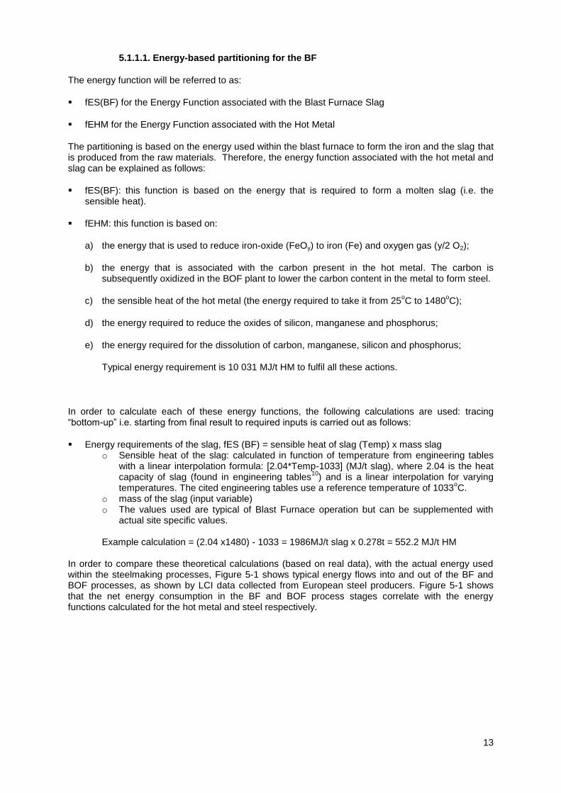
5.1.1.1. Energy-based partitioning for the BF
The energy function will be referred to as:
fES(BF) for the Energy Function associated with the Blast Furnace Slag
fEHM for the Energy Function associated with the Hot Metal
The partitioning is based on the energy used within the blast furnace to form the iron and the slag that is produced from the raw materials. Therefore, the energy function associated with the hot metal and slag can be explained as follows:
fES(BF): this function is based on the energy that is required to form a molten slag (i.e. the sensible heat).
fEHM: this function is based on:
a) the energy that is used to reduce iron-oxide (FeOy) to iron (Fe) and oxygen gas (y/2 O2);
b) the energy that is associated with the carbon present in the hot metal. The carbon is subsequently oxidized in the BOF plant to lower the carbon content in the metal to form steel.
c) the sensible heat of the hot metal (the energy required to take it from 25oC to 1480
oC);
d) the energy required to reduce the oxides of silicon, manganese and phosphorus;
e) the energy required for the dissolution of carbon, manganese, silicon and phosphorus;
Typical energy requirement is 10 031 MJ/t HM to fulfil all these actions.
In order to calculate each of these energy functions, the following calculations are used: tracing “bottom-up” i.e. starting from final result to required inputs is carried out as follows:
Energy requirements of the slag, fES (BF) = sensible heat of slag (Temp) x mass slag o Sensible heat of the slag: calculated in function of temperature from engineering tables
with a linear interpolation formula: [2.04*Temp-1033] (MJ/t slag), where 2.04 is the heat capacity of slag (found in engineering tables
10) and is a linear interpolation for varying
temperatures. The cited engineering tables use a reference temperature of 1033oC.
o mass of the slag (input variable) o The values used are typical of Blast Furnace operation but can be supplemented with
actual site specific values.
Example calculation = (2.04 x1480) - 1033 = 1986MJ/t slag x 0.278t = 552.2 MJ/t HM
In order to compare these theoretical calculations (based on real data), with the actual energy used within the steelmaking processes, Figure 5-1 shows typical energy flows into and out of the BF and BOF processes, as shown by LCI data collected from European steel producers. Figure 5-1 shows that the net energy consumption in the BF and BOF process stages correlate with the energy functions calculated for the hot metal and steel respectively.

14
Figure 5-1: Energy flows into and out of the BF and BOF process
Note other losses such as waste heat have not been quantified.
..
Energy requirements of Hot Metal (fEHM): to create the melt, comprises the sum of:
a) Iron oxide decomposition: reduction of the Fe-oxides in various degrees of oxidation (hematite, magnetite, wustite) which each have a specific formation energy. The degree of oxidation is calculated from: DRI: typically 92% degree of metallization, remainder present as wustite; Ratio of hematite/magnetite in sinter: this is calculated from the mass balance of Fe. First
subtract from total Fe, the Fe in the DRI and slag (typical 0.035% =>0.00035 constant * slag mass). Then apply a stoichiometric interpolation relationship function of the average degree of oxidation, Yzero (typical value 1.47). This interpolation curve [6 * Yzero – 8] can be deduced as with known Fe to O ratio of pure Fe203 and FeO. Their relative ratio can be estimated from Fe to O ratio in the sinter mix. After previous calculations, the remaining fraction will be magnetite.

15
Hematite: interpolation function: Total Fe – Fe from DRI (see above) – Fe dissolved in slag (0.035%). Then apply to the remaining iron fraction the linear interpolation curve as a function of the degree of oxidation, Yzero of the mix [6 * Yzero – 8]
Magnetite: remainder is magnetite calculated as the remaining Fe fraction to close the total Fe balance.
The equation and example calculation of iron oxide decomposition is as follows: (Fe_Hem*Red_Hem+Fe_Mag*Red_Mag+0.07*Fe_DRI*DRI_Rate*Red_Wus)/1000 = 6852 MJ/t HM
Where: Fe Hem = amount of iron present as Haematite = 773 kg/t HM Red Hem = heat of formation from reduction of Hematite = 7372 MJ/t Fe Fe Mag = amount of iron present as Magnetite = 172 kg/t HM Red Mag = heat of formation from reduction of Magnetite = 6690 MJ/t Fe 0.07*Fe DRI* DRI Rate = amount of iron present as Wustite = 0 Red Wus = heat of formation from reduction of Wustite = 5035 MJ/t Fe
b) Energy of carbon in Hot Metal: energy of carbon dissolved & contained in the melt equals
carbon mass * specific energy of formation = 4.62%*32762 MJ/t C = 1514 MJ/t HM

16
c) Sensible heat of the Hot Metal to required temp: calculated by bringing all elements of melt to 1600
oC (engineering tables with sensible heat) and then subtract for each element of the melt
the difference between the actual HM temp and 1600oC, assumed in the first part of the
calculation multiplied with the heat capacity. Example calculation: (α_C*HS_C1600 + α_Si*HS_Si1600 + α_Mn*HS_Mn1600 + α_P*HS_P1600 + α_Fe*HS_Fe1600) + (T_Pig-1600) * (α_C*Cp_C + α_Si*Cp_Si + α_Mn*Cp_Mn + α_P*Cp_P + α_Fe*Cp_Fe) = 1318 MJ/t HM
Where: α_C = carbon in Hot Metal = 4.62% α_Si = silicon in Hot Metal = 0.52% α_Mn = manganese in Hot Metal = 0.32% α_P = phosphorous in Hot Metal = 0.073% α_Fe = iron in Hot Metal = 94.47% HS_C1600 = sensible heat of C at 1600ºC HS_Si1600 = sensible heat of Si at 1600ºC HS_Mn1600 = sensible heat of Mn at 1600ºC HS_P1600 = sensible heat of P at 1600ºC HS_Fe1600 = sensible heat of Fe at 1600ºC T Pig = temperature of pig iron = 1480ºC Cp = heat capacity (of each element C, Si, Mn, P and Fe)
d) Energy for reduction Si, Mn, P
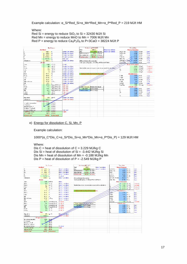
17
Example calculation: α_Si*Red_Si+α_Mn*Red_Mn+α_P*Red_P = 219 MJ/t HM Where: Red Si = energy to reduce SiO2 to Si = 32430 MJ/t Si Red Mn = energy to reduce MnO to Mn = 7006 MJ/t Mn Red P = energy to reduce Ca3P2O8 to P+3CaO = 38224 MJ/t P
e) Energy for dissolution C, Si, Mn, P Example calculation: 1000*(α_C*Dis_C+α_Si*Dis_Si+α_Mn*Dis_Mn+α_P*Dis_P) = 129 MJ/t HM Where: Dis C = heat of dissolution of C = 3.229 MJ/kg C Dis Si = heat of dissolution of Si = -3.442 MJ/kg Si Dis Mn = heat of dissolution of Mn = -0.188 MJ/kg Mn Dis P = heat of dissolution of P = -2.549 MJ/kg P

18
Based on these energy functions above, and the mass of the hot metal/crude steel and the slag that is produced in the process, the partitioning ratio between the hot metal/crude steel and slag can be calculated. This ratio is then used to allocate the associated burdens of the inputs and the outputs between the hot metal and slag using the Blast Furnace as an example:
For the hot metal:
)(BFFESfEHM
fEHM
For the slag:
)(
)(
BFFESfEHM
BFfES
In summary the energy partitioning ratio resulting from the above calculations is shown below using example values. Actual values will vary according to the specific site, due to differences in raw material inputs, temperatures and slag volumes.
Blast Furnace energy partitioning ratio:
For the hot metal, fEHM: %8.9410055210031
10031
For the BF slag, fES(BF): %2.510055210031
552
5.1.1.2. Energy-based partitioning for the BOF
The energy function will be referred to as:
fEST for the Energy Function associated with the Crude Steel
fES(BOF) for the Energy Function associated with the BOF Slag
The partitioning is based on the energy used within the BOF to form the crude steel and the slag that is produced from the raw materials. Therefore, the energy function associated with the crude steel and slag can be explained as follows:
fEST: this function is based on the energy required for the steel to reach the required temperature in the steelmaking vessel (i.e. the sensible heat). = heat capacity of iron x liquid temperature + 32. Example calculation:
0.824MJ/t/K x 1650ºC + 32 = 1 392 MJ/t steel
0.824 is the heat capacity of iron found in engineering tables10
1650ºC is a typical target temperature for steel in the BOF vessel9. This is higher than the
temperature of hot metal due to the exothermic reaction in the BOS vessel
fES(BOF): this function is based on the energy that is required to form a molten slag (i.e. the sensible heat) = Amount of slag in kg x (heat capacity of steel slag x liquid temperature -1120)/1000. Example calculation:
97kg/t steel x (2.04MJ/t/K x 1650 ºC -1120)/1000 = 218 MJ/t steel
10 Techniques de l'ingénieur - 10-1980 pp M1726-1 to M1728-8

19
Figure 5-1 shows typical energy flows into and out of the BF and BOF processes. As the BOF process is an exothermic reaction, the main energy input into the process comes in the hot metal and only a small amount of additional energy is added (0.33 GJ/t). This figure shows the energy flows of the system.
Basic Oxygen Furnace energy partitioning ratio:
For the steel, fEST: %4.861002181392
1392
For the steel slag, fES(BOF): %6.131002181392
218
5.1.2. Ferrous content
Some flows are iron carriers but also have a significant amount of gangue that enters the slag. The flow is then allocated between the slag based on the ferrous and gangue contents.
Calculation of gangue content: Calculations are carried out based on the difference (rest fraction) calculated from input value / Fe content and the weight of the oxygen chemically bound to the iron. The latter is based on the degree of oxidation of the iron (typical value 1.45 as a result of reduction to FeO and partly reoxidation at the surface to Fe3O4) multiplied with relative oxygen weight (factor 16/55.85 based on the atomic mass of O and Fe);
o Sinter: Sinter is an iron carrier but also has an amount of gangue that enters the slag. The flow is then allocated between the slag based on the ferrous and gangue contents of the sinter.
Example calculation:1 - (Fe_Sinter+1.45*Fe_Sinter*(16/55.85)) = 18.3% gangue content
Where: Fe Sinter = iron content of sinter = 57.7%
o Pellet: Pellet is an iron carrier but also has an amount of gangue that enters the slag. The flow is then allocated between the slag based on the ferrous and gangue contents of the pellets. Example calculation: 1 - (Fe_Pellets+1.5*Fe_Pellets*(16/55.85))= 7.1% gangue content Where: Fe Pellets = iron content of pellets = 65%

20
o Iron ore (lump): iron ore is an iron carrier but also has an amount of gangue that enters the slag. The flow is then allocated between the slag based on the ferrous and gangue contents of the iron ore (lump).
Example calculation: 1 - (Fe_Lump+1.5*Fe_Lump*(16/55.85))= 11.4% gangue content Where: Fe_Lump = iron content of iron ore (lump) = 62%
o DRI: Calculation for the gangue content of DRI based on rest fraction takes into account the following:
Fe content in DRI Fraction of Fe content that is in not in metalised status [1- DRI_metallisation]
for which the weight has to be augmented with chemically bound oxygen. As oxidation degree a factor 1.056 (close to FeO) is a typical value (default) to be further multiplied with ratio of atomic mass between O and F (as done in calculations above);
Fraction of C in DRI Example calculation: 1 - (Fe_DRI+1.056*(1-Met_DRI)*Fe_DRI*(16/55.85))-C_DRI = 4.1% gangue Where:
Fe DRI = iron content of DRI = 92% Met DRI = fraction of iron in DRI which is metallised = 93%
C DRI = fraction of C in DRI = 2%
5.1.3. 100% slag
This applies to flows that are added only to improve the quality or processability of the slag (e.g. fluorspar to control viscosity).
5.1.4. Hot metal purity
This applies to the hot metal input to the BOF from the blast furnace. The partitioning of the hot metal input between the steel and the slag is determined by the proportion of impurities that are present in the hot metal inputs (i.e. silicon, manganese and phosphorus), as these impurities form part of the slag. These impurities come in with the hot metal (probably from the iron ore and other sources) and will be oxidised when oxygen is blown into the BOF via the oxygen lance.
21
5.1.5. 100% hot metal
This applies to flows that are added only to improve the quality or processability of the hot metal (e.g. additions of manganese that can be added in the BOF after the oxygen blowing, in order to achieve the desired chemistry of the steel product as part of the secondary steelmaking process.
5.1.6. 100% crude steel
This applies to flows that are added only to improve the quality or processability of the crude steel.
5.1.7. System expansion for process gases
System expansion is used to account for the excess BF and BOF gases that leave the product system boundary, either for use to make other steel products in upstream or downstream processes (replacing the need for other fuels), or exported off site (replacing the need for other fuels or contributing to the national electricity grid). The avoided burden of the relevant fuel or electricity grid mix is applied to the data. This process of system expansion occurs after partitioning of the metal and slag in the BF and BOF process. In both cases, the output of the excess process gas is split between the hot metal or steel and the slags based on the energy partitioning functions fEHM, fES (BF), fEST, fES (BOF). Given that the overall intention of an integrated steelmaking site is to achieve an overall balance in its process gas production and consumption on site, any burdens or benefits of excess gas exported for a given steel product have to be allocated between the product and the slag by energy given that the production of these gases is ultimately energy based. The net effect of system expansion for the process gases is often an increase of the CO2 burden for steel and slag manufacture due to the relatively high carbon intensity of the gases compared to alternative fuels used for heat and power generation.
Any emissions associated with the flaring of process gases are allocated all to the hot metal or steel product as they are waste disposal operations related to operational matters.
5.2. Coke ovens
Co-products are coke, coke oven gas, tar, BTX (Benzene, Toluene, Xylene) and sulphur.
The coke oven co-products are mainly energy-based products i.e. with a significant calorific value, and so the inputs and outputs related to the production of these co-products are partitioned based on the ratios of the total energy content (net calorific value, NCV) of each of them. The partitioning of the flows between the co-products is determined in the following way, taking coke as an example:
)()( .. coproductsothercoproductsothercokecoke
cokecoke
MassNCVMassNCV
MassNCV
Based on average data, the coke product and coke oven gas used in making hot metal represents 82.9% of the total energy and remaining energy is contained in the co-products and gas used for other steelmaking processes.
The exceptions to this methodology are steam and hot water sometimes generated during coke making (approximately 1% of the total energy outputs produced, less than 0.5 GJ per tonne). As they are generally used internally within the steel making process, and to avoid further complications in allocation principles in other process units (see blast furnace below), they are dealt with by system expansion (as detailed in appendix 9 of the worldsteel methodology report 2011) but only in the case when their use falls outside of the system boundary of the products being assessed. Their use replaces the need for steam or hot water produced by alternative means (see section 2.5).
For the input of coke oven gas into each process, the LCI for the gas is calculated based on the energy of the coke oven gas, using the equation above for allocating impacts of coke ovens between co-products.

22
5.3. Sinter and pellet plant
Product is sinter or pellet.
The only product from this process is sinter or pellet and so no allocation is required.
5.4. Blast Furnace
Main co-products are hot metal (pig iron) and slag.
Within the blast furnace process, straight partitioning is complex as the process gases are often recovered internally and used within the steel making process and the other two co-products (hot metal, slag) are for external use. The process gases are dealt with by system expansion as they are often used internally, thus avoiding the production of electricity in the power plant. It is unlikely that other industries will require an LCI for the use of blast furnace gas as a co-product, which would result in a high carbon footprint. The process gas produced in the blast furnace can have different functions, but all activities associated with the gas (internal use as heating or electricity, exported surplus) are partitioned (burdens and credits) in the same way, according to the energy-based rule in the blast furnace, between the hot metal and the slag.
Over 94% of blast furnace slag is used as a by-product. Any slag that is actually disposed of as a waste is assigned to the hot metal. In order to calculate this, the burdens required to make slag are first allocated to the total volume of slag produced. The burdens associated with the proportion of slag that is disposed of is then added back onto the hot metal LCI. This means that any slag that is disposed as a waste has no allocated burdens.
Once the inputs and outputs of the blast furnace process have been partitioned between the hot metal and the slag (see section 5.1.7.) system expansion is then carried out for the BF gas. All the impacts associated with export of the blast furnace gas are applied to the hot metal and the slag in the ratio of the energy allocation i.e. 94.8% onto the Hot Metal (fEHM), and 5.2% onto the slag (fES (BF)).
For all relevant flows, the partitioning method is described and justified in detail below, choosing from one of the methods listed above.
CO and CO2 are produced (and some CH4) during the combustion of coal and coke in the blast furnace which are used to trigger the reactions of the production process (producing hot metal, slag and gases). These emissions to air are therefore partitioned between the hot metal and the slag, based on the energy function (fEHM and fES(BF)).
Energy sources e.g. natural gas, coal, coke: these are used in the operation of the process and therefore associated with both the hot metal and the slag and thus partitioned in this manner, based on the energy function (fEHM and fES(BF)). The contribution of blast furnace gas is determined by system expansion to calculate the burden of process gas combustion as well as the credit due to the avoided production of electricity, which are also applied to the hot metal and slag based on the energy function. Via these energy sources, a very limited amount of N2O is produced in these combustion processes, which is also split between the hot metal and the slag, based on the energy function.
Fluorspar – is added to control the slag viscosity and is therefore partitioned totally to the slag.
Hydrogen sulphide, H2S (air emission), is partitioned to both the hot metal and the slag by the energy function (fEHM and fES(BF)) as, although the emissions of the H2S mainly occur during quenching of the slag at the slag pouring tap, this has no more link (metallurgically) to the slag than to the hot metal.
Iron ore, sinter, pellets, sinter fines and direct reduced iron – partitioning between the slag and hot metal of these flows is calculated based on the proportion of gangue and iron that is present in the material. Gangue content is defined as the non-iron content of the material and is determined by calculating the iron/ferrous content in the material – the proportion of the material that is iron is therefore partitioned to the hot metal. The gangue content in the iron ore is calculated based on the

23
iron content using the formula: [gangue = 1 – (1.43 * iron content)], where the 1.43 relates to the proportion of iron ore (which is a mix of haematite, Fe2O3, and gangue) that is iron (see §5.1.2). Where no site specific data is available, default values are used instead. The gangue forms the slag product and therefore the proportion of gangue content is partitioned to the slag.
The benefits of having gangue present in the sinter product is that it produces a material that can be inserted into the blast furnace due to its hardness and using such products produces a good quality slag that can beneficially be used by industries such as the cement industry.
Inputs Default Gangue content* %
Sinter (fines) 18.3
Pellets 7.1
Iron ore 11.4
DRI 4.1
Table 3: Default gangue content values
*based on ArcelorMittal data – to be updated at a later stage when site specific information available
Iron Scrap inputs are added for iron content and are therefore totally partitioned to the hot metal.
Limestone (CaCO3) is added to the blast furnace and has many functions within the steel making process. It is used to remove the gangue from the iron ore, in order to clean it, and also to aid with the slag formation. It enables the slag to reach a specific basicity and the liquidus temperature required, with correct calcium levels, and therefore enables it to be decanted, and to create a granulated slag. The limestone is partitioned between the hot metal and the slag, on the basis of the energy function (fEHM and fES(BF)), which results in the hot metal taking most of the burden for the limestone.
This is also the reason why the dolomite (CaCO3.MgCO3), bauxite and olivine inputs are partitioned between the metal and the slag by the energy function (fEHM and fES(BF)).
Metallic additions (e.g. Manganese) – these are added in order to achieve the correct steel grade and therefore partitioned to the hot metal.
Scales and Steel Scrap are added as recycling iron units and therefore the entire burden is associated with the hot metal.
Sodium carbonate is added at the hot metal desulphurisation stand, and the formed slag is stripped out and not mixed to the BF/BOF slag (steel slag). For this reason it should be completely partitioned to the hot metal.
Steam as an energy input is partitioned by the energy function (fEHM and fES(BF)) to both the hot metal and the slag. Steam used in the wastewater treatment process, or occurring as an output, is also partitioned to both the hot metal and the slag by the energy function (fEHM and fES(BF)).
Water – is used for the granulation and cooling of slag, process cooling water and for the cleaning of the gases (CO, CO2, CH4). Water is therefore partitioned to both the hot metal and the slag by the energy function (fEHM and fES(BF)).
Wastewater treatment - as the wastewater comes from the cleaning of the gases, which are partitioned by the energy function (fEHM and fES(BF)) to both the hot metal and the slag, it follows that the water treatment process is partitioned in the same manner. Thus, the water used, the treatment chemicals, and the discharges produced (wastewater/sludges) are partitioned by the energy function (fEHM and fES(BF)) to both the hot metal and the slag.
Miscellaneous: packaging is partitioned to the steel; covering powder is added to the ladles to reduce heat loss from the steel and is therefore partitioned to the steel.

24
5.5. Basic Oxygen Furnace (BOF)
Main co-products are the steel product and the slag.
The main inputs and outputs are partitioned using either the energy function calculations (fEST (energy function of steel) and fES(BOF)), gangue calculations, or are directly attributable to one or other of the co-products, as has been described above. In addition, there are a number of additional allocation rules which are applicable to the BOF:
Additions (e.g. calcium carbide) or specific slags / sludges / dusts / scales produced (e.g. desulphurisation slag) which are required or produced in order to achieve the desired steel grade, are partitioned to the steel.
Additions (e.g. gases used for the removal of inclusions in the steel or for mixing, covering powder in the ladles to reduce heat loss) and outputs produced (e.g. grease used in the casting process, scrap and sludge produced) specifically for the actual steelmaking process and with no relevance to the slag, are partitioned to the steel.
Oxygen and associated CO2 emissions: Oxygen is injected into the furnace in order to lower the carbon content of the hot metal to make steel. For this reason the oxygen input is partitioned to the steel. Subsequent CO2 emissions are formed from the oxidation of the carbon and so this direct emission is also partitioned to the steel.
Manganese: Any manganese added such as ferromanganese, is partitioned to the steel as it is added for the steel grade.
In the BOF process, the manganese dust/sludge comes from Manganese as part of the Hot Metal composition which is oxidised during the blowing phase. It does not come from the addition of manganese as an alloying element which occurs at the metallurgical stand. For hot metal inputs, the allocation is split between the hot metal and the slag by determining the proportion of impurities that are present in the hot metal inputs (e.g. Silicon, Manganese and Phosphorus), and allocating this proportion of impurities to the slag. These impurities come in with the hot metal (probably from the iron ore) and will be oxidised when oxygen is blown into the BOF via the oxygen lance. Manganese can be added after the oxygen blowing in order to achieve the desired chemistry.
Synthetic slag is added to the process after the production of the BOF slag and therefore it is partitioned to the steel.
Any slag that is actually disposed of as a waste is partitioned to the steel product. In order to calculate this, the burdens partitioned to the slag are first assigned to the total volume of slag produced. The burdens associated with the proportion of slag that is disposed of is then added back onto the hot metal LCI. This means that any slag that is disposed as a waste has no allocated burdens.
5.6. Hot Rolling
Product is hot rolled coil.
The only product from this process is hot rolled coil and so no partitioning is required and all flows are assigned to the coil.
5.7. Electric Arc Furnace (EAF) and the Stainless Steel EAF
Co-products are the steel product and slag.
Partitioning rules for the EAF processes, for both carbon and stainless steel, will follow similar principles as for the BOF process described above, with further rules for additional flows within the process. However, the analysis of such data is not considered in this report here.

25
6. IMPLEMENTATION
This co-product approach is implemented within the worldsteel LCI model as set-up in the LCA software system, GaBi. To cope with the individual partitioning requirements of this co-product approach the GaBi feature “Extended Manual Allocation” is used which supports the application of individual allocation (partitioning) rules on the level of single input/output flows per process.
Figure 6-1: Extended manual allocation in worldsteel GaBi model, Blast Furnace process
Figure 6-1 illustrates the application of this co-product approach using the example of the blast furnace. The use of this GaBi feature allows the application of input/output specific allocation (partitioning) rules not only per process but also differentiating the single site specific process situation.
7. RESULTS OF METHODOLOGY TO BE INCORPORATED
Using the existing European steel production process data in the GaBi model (taken from the 2010 worldsteel database), an analysis between the existing data developed by worldsteel using system expansion and this newly developed co-product methodology based on sub-division by physical partitioning using flow-specific rules is undertaken in order to determine whether the LCI associated with the steel and the slag is justifiable and within a reasonable order of magnitude. Verification with the industries utilising the steel industry co-products, e.g. the cement industry, will be undertaken to cross-check the relevance of the co-product LCIs developed with the present methodology. To reflect the fact that the use of these co-products is more beneficial to the environment than using products manufactured from virgin raw materials, the burden of using such co-products as a general rule is lower than that for using virgin raw materials.
The model has been developed within the GaBi LCA software, in conjunction with the worldsteel methodology and model. All European Integrated steelworks have been utilised to determine the effect of applying this new co-product methodology, to determine the range of environmental burdens that should be associated with the steel industry co-products. An average of the results of these sites has been produced to determine a European LCI for these co-products for analysis purposes as well as to start the discussions with the corresponding industries.
Variations in the results between each site will occur and are mainly due to the different input/output characteristics of the steelmaking processes of relevance (coke plant, blast furnace, BOF) as well as
Definition of individual allocation rules….
To be applied (and specified) for each individual input/output…
Definition of individual allocation rules….
To be applied (and specified) for each individual input/output…

26
due to the different site specific boundary conditions such as the use of process gas on site, export of process gas for external use, the process-internal production of steam, hot water etc. This will therefore reflect the actual fate of these co-products instead of their potential fate (how much is actually reused, flared etc.) and will thus encourage the utilisation of these materials as opposed to their disposal. For example, those sites which flare their gas will have a higher burden to be allocated to the steel product than those where the gas is utilised or exported for use elsewhere.
The resulting life cycle inventories calculated, based on the average of European sites, are included in Table 4 below. The calculations are based on the data from the latest LCI study from 2010, including the background data used at that time. The results show that the new allocation method affects the steel product LCI by a relatively small amount (typically <5%).

27
Note: Total water represents the sum of all net water inputs for 1kg Hot Rolled Coil Note: Data for illustration purposes only, not for use for specific results.
Table 4: The LCI result for 1kg of Hot Rolled Coil, calculated on the basis of this new co-product approach as well as the LCI using the 2011 worldsteel methodology of system expansion.
Table 5: shows the differences between the allocation achieved for 1kg BF slag using this new proposed allocation approach and the credit system used in the existing worldsteel methodology (system expansion) for 1kg cement, embankment and fertiliser production. Note that the worldsteel model takes a credit for cement production based on CEM1 and CEM III, which already incorporates some substitution using BF and steel slag. If based on just CEM1 (virgin Portland cement) the CO2 emissions being substituted would be even higher at 0.90 kg CO2/kg (CEMBUREAU data in GaBi). The BF slag allocation is based on the European site data taken from the worldsteel 2010 LCI data release. Table 6 below shows the same as Table 5, except using the comparison of BOF slag.
System expansion method New allocation method
Resources Crude oil 0.0106 0.0272
Resources Hard coal 0.7500 0.6352
Resources Natural gas 0.0106 0.0108
Resources Dolomite 0.0174 0.0168
Resources Iron ore 1.3568 1.1678
Resources Limestone (calcium carbonate) 0.0182 0.2423
Resources Zinc ore 1.44E-10 1.38E-10
Resources Water 0.03247 0.0361
Resources Water (drinking) - -
Resources Water (fresh) 4.8685 4.2981
Resources Water (ground) 1.6282 1.5114
Resources Water (lake) 1.53E-14 1.685E-14
Resources Water (river) 3.04E-14 1.008E-12
Resources Water (sea) 6.4944 1.4989
Resources Water (surface) 1.2770 1.3541
Resources Total water 15.8838 10.4590
Emissions to air Cadmium 6.93E-08 5.06E-08
Emissions to air Chromium (unspecified) 1.59E-07 1.34E-07
Emissions to air Lead 3.01E-06 2.53E-06
Emissions to air Mercury 7.17E-08 7.05E-08
Emissions to air Zinc 2.68E-06 2.54E-06
Emissions to air Carbon dioxide 1.9669 1.9476
Emissions to air Carbon monoxide 0.0237 0.0195
Emissions to air Hydrogen chloride 3.529E-05 3.079E-05
Emissions to air Hydrogen sulphide 4.964E-05 4.409E-05
Emissions to air Nitrogen oxides 0.0022 0.0021
Emissions to air Nitrous oxide (laughing gas) 7.071E-06 6.822E-06
Emissions to air Sulphur dioxide 0.0025 0.0012
Emissions to air Dioxins (unspecified) 8.763E-13 7.807E-13
Emissions to air NMVOC (unspecified) 0.0003 0.0002
Emissions to air Methane 0.0054 0.0046
Emissions to air Dust (unspecified) 0.0010 0.0009
Emissions to fresh water Chemical oxygen demand (COD) 0.0001 0.0001
Emissions to fresh water Cadmium 3.000E-08 2.738E-08
Emissions to fresh water Chromium (unspecified) 3.718E-08 3.820E-08
Emissions to fresh water Iron 4.043E-07 2.420E-05
Emissions to fresh water Lead 1.574E-08 1.451E-08
Emissions to fresh water Nickel 4.612E-05 7.448E-08
Emissions to fresh water Zinc 2.515E-07 1.184E-07
Emissions to fresh water Ammonia (NH4+, NH3, as N) 2.837E-05 2.288E-05
Emissions to fresh water Nitrogen 4.114E-06 4.211E-06
Emissions to fresh water Phosphorus 5.706E-07 5.411E-07
Emissions to fresh water Solids (suspended) 0.0006 0.0005
1kg Hot Rolled Coil

28
As can be seen from Table 5 and Table 6, the CO2 emissions allocated to BF and steel slag are substantially lower than that of the products they substitute, with the exception of aggregate production (embankment). In the case of the worldsteel model, the embankment substituted is that of gravel, which requires little processing and is often simply dredged from the sea bed. This is a conservative approach on the part of worldsteel for the purposes of system expansion. In reality the aggregate being substituted may be crushed rock from a quarry, which requires the use of explosives and crushing equipment. The CO2 emissions associated with crushed rock (limestone) is substantially higher at 0.03 kg CO2/kg compared to 0.002 kg CO2/kg embankment LCI used by worldsteel.

29
Note: Total water represents the sum of all net water inputs for 1kg slag-substituted product Note: Data for illustration purposes only, not for use for specific results.
Table 5: LCI of 1kg BF slag (EU 2010 average): comparison with the 2011 worldsteel methodology of system expansion
BF
Slag
ro
ute
-
aver
age
(bas
ed o
n E
U
dat
a)
Cem
ent
pro
du
ctio
n
(CEM
I an
d II
I as
in
wo
rld
stee
l met
ho
d)
CEM
I
Emb
ankm
ent
Fert
ilise
r
Resources Crude oil 6.26E-03 1.30E-02 1.44E-02 2.45E-04 1.32E-02
Resources Hard coal 3.89E-02 3.89E-02 4.37E-02 1.74E-04 5.76E-02
Resources Natural gas 1.23E-03 4.80E-03 5.33E-03 5.58E-05 6.09E-02
Resources Dolomite 1.79E-03 3.56E-09 4.07E-09 5.52E-11 1.49E-09
Resources Iron ore 8.04E-01 1.09E-02 1.23E-02 1.25E-09 3.57E-08
Resources Limestone (calcium carbonate) 1.27E-01 1.55E+00 1.73E+00 3.09E-05 1.94E+00
Resources Zinc ore 1.54E-06 2.49E-13 7.33E-06 1.13E-17 6.41E-16
Resources Water 2.89E-01 4.65E-03 4.66E-03 1.82E-05 1.63E-04
Resources Water (drinking) - - - - -
Resources Water (fresh) 3.62E-01 - - - -
Resources Water (ground) 4.02E-01 6.21E-01 6.95E-01 3.65E-03 3.53E-01
Resources Water (lake) 3.47E-19 - - - -
Resources Water (river) 8.74E-13 6.20E-14 6.24E-14 1.88E-20 1.15E-15
Resources Water (sea) 9.03E-01 2.39E-04 2.60E-04 6.71E-06 3.85E-05
Resources Water (surface) 2.25E-01 9.37E-01 1.05E+00 1.04E-02 2.07E-01
Resources Total water 2.18E+00 1.56E+00 1.75E+00 1.41E-02 5.59E-01
Emissions to air Cadmium 3.21E-08 8.78E-09 9.78E-09 4.09E-12 9.97E-11
Emissions to air Chromium (unspecified) 4.86E-08 1.43E-09 1.62E-09 2.06E-11 5.83E-10
Emissions to air Lead 1.70E-06 9.48E-08 1.06E-07 1.42E-10 3.37E-09
Emissions to air Mercury 3.64E-08 3.56E-08 3.97E-08 2.49E-11 1.07E-07
Emissions to air Zinc 4.20E-07 1.96E-07 2.19E-07 4.14E-10 8.16E-09
Emissions to air Carbon dioxide 4.84E-01 7.17E-01 7.99E-01 2.00E-03 1.20E+00
Emissions to air Carbon monoxide 1.35E-02 1.41E-03 1.57E-03 3.59E-06 1.14E-04
Emissions to air Hydrogen chloride 1.59E-05 5.32E-06 5.95E-06 1.17E-08 1.49E-06
Emissions to air Hydrogen sulphide 1.10E-05 1.72E-07 1.88E-07 2.01E-09 6.49E-07
Emissions to air Nitrogen oxides 8.87E-04 1.36E-03 1.51E-03 1.20E-05 3.44E-04
Emissions to air Nitrous oxide (laughing gas) 1.79E-06 4.70E-06 5.31E-06 4.73E-08 2.91E-06
Emissions to air Sulphur dioxide 2.69E-04 3.34E-04 3.74E-04 2.55E-06 1.71E-04
Emissions to air Dioxins (unspecified) 5.89E-13 3.01E-17 3.32E-17 4.97E-19 1.86E-16
Emissions to air NMVOC (unspecified) 1.10E-04 1.03E-05 1.10E-05 1.18E-06 2.34E-05
Emissions to air Methane 1.27E-03 5.00E-04 5.60E-04 3.19E-06 8.64E-04
Emissions to air Dust (unspecified) 1.20E-04 1.67E-04 1.78E-04 2.32E-07 4.52E-05
Emissions to fresh water Chemical oxygen demand (COD) 1.99E-05 3.39E-05 3.51E-05 3.57E-07 1.20E-05
Emissions to fresh water Cadmium 7.32E-09 4.54E-09 5.09E-09 5.90E-11 8.01E-09
Emissions to fresh water Chromium (unspecified) 1.76E-09 9.52E-09 1.06E-08 1.31E-10 1.16E-08
Emissions to fresh water Iron 0.00E+00 1.30E-04 1.47E-04 9.13E-07 7.98E-05
Emissions to fresh water Lead 0.00E+00 1.89E-08 2.17E-08 3.07E-10 1.14E-08
Emissions to fresh water Nickel 2.10E-08 9.08E-09 1.02E-08 9.85E-11 1.54E-08
Emissions to fresh water Zinc 3.63E-08 1.29E-08 1.45E-08 1.22E-10 1.64E-08
Emissions to fresh water Ammonia (NH4+, NH3, as N) 6.40E-06 0.00E+00 0.00E+00 0.00E+00 0.00E+00
Emissions to fresh water Nitrogen 2.16E-06 6.48E-08 6.50E-08 6.73E-13 2.09E-09
Emissions to fresh water Phosphorus 9.40E-08 1.05E-08 1.12E-08 1.17E-10 2.65E-08
Emissions to fresh water Solids (suspended) 1.15E-04 9.73E-05 1.08E-04 1.21E-06 4.20E-04
Absolute, kg

30
Note: Total water represents the sum of all net water inputs for 1kg slag-substituted product Note: Data for illustration purposes only, not for use for specific results.
Table 6: LCI of 1kg BOF slag (EU 2010 average): comparison with current worldsteel methodology of system expansion
BO
F Sl
ag r
ou
te -
ave
rage
Cem
ent
pro
du
ctio
n (
CEM
I an
d
III a
s in
wo
rld
stee
l met
ho
d)
Emb
ankm
ent
Fert
ilise
r
Resources Crude oil 4.20E-03 1.30E-02 2.45E-04 1.32E-02
Resources Hard coal 0.055328 3.89E-02 1.74E-04 5.76E-02
Resources Natural gas -0.00119 4.80E-03 5.58E-05 6.09E-02
Resources Dolomite 0.019689 3.56E-09 5.52E-11 1.49E-09
Resources Iron ore 0.10776 1.09E-02 1.25E-09 3.57E-08
Resources Limestone (calcium carbonate) 0.12678 1.55E+00 3.09E-05 1.94E+00
Resources Zinc ore 8.02E-12 2.49E-13 1.13E-17 6.41E-16
Resources Water 0.000453 4.65E-03 1.82E-05 1.63E-04
Resources Water (drinking) - - - -
Resources Water (fresh) 1.983503 - - -
Resources Water (ground) 0.14553 6.21E-01 3.65E-03 3.53E-01
Resources Water (lake) 3.27E-19 - - -
Resources Water (river) 8.23E-13 6.20E-14 1.88E-20 1.15E-15
Resources Water (sea) 0.423714 2.39E-04 6.71E-06 3.85E-05
Resources Water (surface) 0.125487 9.37E-01 1.04E-02 2.07E-01
Resources Total water 2.70E+00 1.56E+00 1.41E-02 5.59E-01
Emissions to air Cadmium 1.74E-08 8.78E-09 4.09E-12 9.97E-11
Emissions to air Chromium (unspecified) 4.43E-08 1.43E-09 2.06E-11 5.83E-10
Emissions to air Lead 6.01E-07 9.48E-08 1.42E-10 3.37E-09
Emissions to air Mercury 1.25E-08 3.56E-08 2.49E-11 1.07E-07
Emissions to air Zinc 2.02E-06 1.96E-07 4.14E-10 8.16E-09
Emissions to air Carbon dioxide 0.35555 7.17E-01 2.00E-03 1.20E+00
Emissions to air Carbon monoxide 0.003295 1.41E-03 3.59E-06 1.14E-04
Emissions to air Hydrogen chloride 2.77E-06 5.32E-06 1.17E-08 1.49E-06
Emissions to air Hydrogen sulphide 3.58E-06 1.72E-07 2.01E-09 6.49E-07
Emissions to air Nitrogen oxides 0.000168 1.36E-03 1.20E-05 3.44E-04
Emissions to air Nitrous oxide (laughing gas) 1.68E-07 4.70E-06 4.73E-08 2.91E-06
Emissions to air Sulphur dioxide 0.00013 3.34E-04 2.55E-06 1.71E-04
Emissions to air Dioxins (unspecified) 1.48E-13 3.01E-17 4.97E-19 1.86E-16
Emissions to air NMVOC (unspecified) 1.98E-05 1.03E-05 1.18E-06 2.34E-05
Emissions to air Methane 0.000348 5.00E-04 3.19E-06 8.64E-04
Emissions to air Dust (unspecified) 8.40E-05 1.67E-04 2.32E-07 4.52E-05
Emissions to fresh water Chemical oxygen demand (COD) 1.20E-05 3.39E-05 3.57E-07 1.20E-05
Emissions to fresh water Cadmium 5.02E-10 4.54E-09 5.90E-11 8.01E-09
Emissions to fresh water Chromium (unspecified) - 9.52E-09 1.31E-10 1.16E-08
Emissions to fresh water Iron 5.82E-06 1.30E-04 9.13E-07 7.98E-05
Emissions to fresh water Lead 1.49E-09 1.89E-08 3.07E-10 1.14E-08
Emissions to fresh water Nickel -9.77E-09 9.08E-09 9.85E-11 1.54E-08
Emissions to fresh water Zinc 2.57E-08 1.29E-08 1.22E-10 1.64E-08
Emissions to fresh water Ammonia (NH4+, NH3, as N) 6.61E-07 0.00E+00 0.00E+00 0.00E+00
Emissions to fresh water Nitrogen 3.72E-07 6.48E-08 6.73E-13 2.09E-09
Emissions to fresh water Phosphorus 3.86E-08 1.05E-08 1.17E-10 2.65E-08
Emissions to fresh water Solids (suspended) 3.27E-05 9.73E-05 1.21E-06 4.20E-04
Absolute, kg
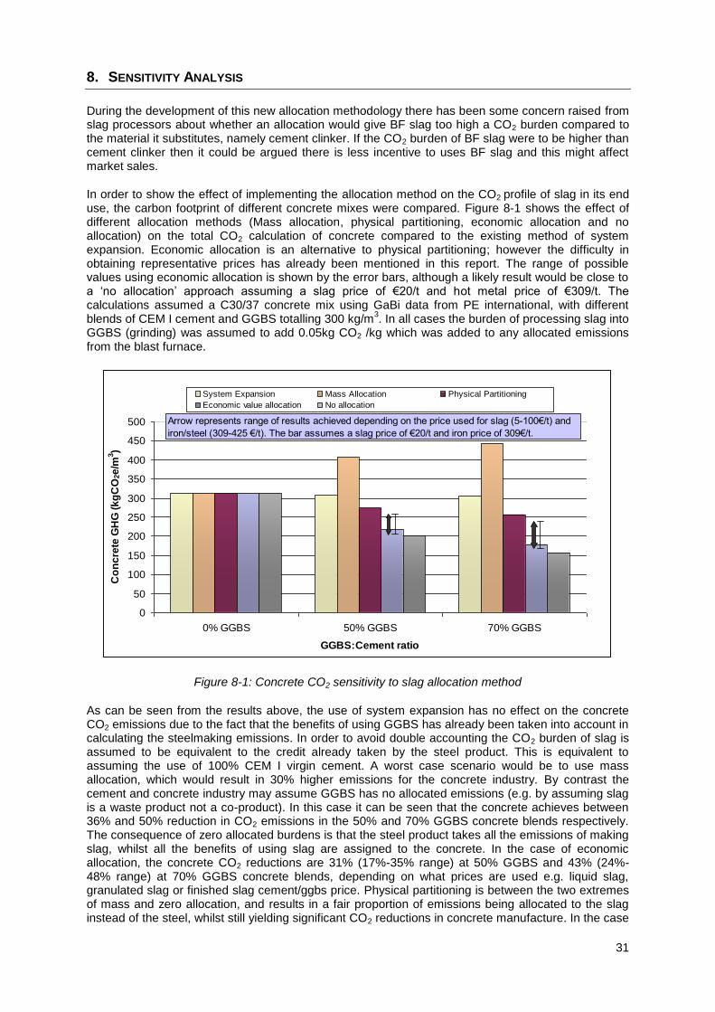
31
8. SENSITIVITY ANALYSIS
During the development of this new allocation methodology there has been some concern raised from slag processors about whether an allocation would give BF slag too high a CO2 burden compared to the material it substitutes, namely cement clinker. If the CO2 burden of BF slag were to be higher than cement clinker then it could be argued there is less incentive to uses BF slag and this might affect market sales.
In order to show the effect of implementing the allocation method on the CO2 profile of slag in its end use, the carbon footprint of different concrete mixes were compared. Figure 8-1 shows the effect of different allocation methods (Mass allocation, physical partitioning, economic allocation and no allocation) on the total CO2 calculation of concrete compared to the existing method of system expansion. Economic allocation is an alternative to physical partitioning; however the difficulty in obtaining representative prices has already been mentioned in this report. The range of possible values using economic allocation is shown by the error bars, although a likely result would be close to a ‘no allocation’ approach assuming a slag price of €20/t and hot metal price of €309/t. The calculations assumed a C30/37 concrete mix using GaBi data from PE international, with different blends of CEM I cement and GGBS totalling 300 kg/m
3. In all cases the burden of processing slag into
GGBS (grinding) was assumed to add 0.05kg CO2 /kg which was added to any allocated emissions from the blast furnace.
Figure 8-1: Concrete CO2 sensitivity to slag allocation method
As can be seen from the results above, the use of system expansion has no effect on the concrete CO2 emissions due to the fact that the benefits of using GGBS has already been taken into account in calculating the steelmaking emissions. In order to avoid double accounting the CO2 burden of slag is assumed to be equivalent to the credit already taken by the steel product. This is equivalent to assuming the use of 100% CEM I virgin cement. A worst case scenario would be to use mass allocation, which would result in 30% higher emissions for the concrete industry. By contrast the cement and concrete industry may assume GGBS has no allocated emissions (e.g. by assuming slag is a waste product not a co-product). In this case it can be seen that the concrete achieves between 36% and 50% reduction in CO2 emissions in the 50% and 70% GGBS concrete blends respectively. The consequence of zero allocated burdens is that the steel product takes all the emissions of making slag, whilst all the benefits of using slag are assigned to the concrete. In the case of economic allocation, the concrete CO2 reductions are 31% (17%-35% range) at 50% GGBS and 43% (24%-48% range) at 70% GGBS concrete blends, depending on what prices are used e.g. liquid slag, granulated slag or finished slag cement/ggbs price. Physical partitioning is between the two extremes of mass and zero allocation, and results in a fair proportion of emissions being allocated to the slag instead of the steel, whilst still yielding significant CO2 reductions in concrete manufacture. In the case
0
50
100
150
200
250
300
350
400
450
500
0% GGBS 50% GGBS 70% GGBS
GGBS:Cement ratio
Co
nc
rete
GH
G (
kg
CO
2e
/m3)
System Expansion Mass Allocation Physical Partitioning
Economic value allocation No allocation
Arrow represents range of results achieved depending on the price used for slag (5-100€/t) and
iron/steel (309-425 €/t). The bar assumes a slag price of €20/t and iron price of 309€/t.
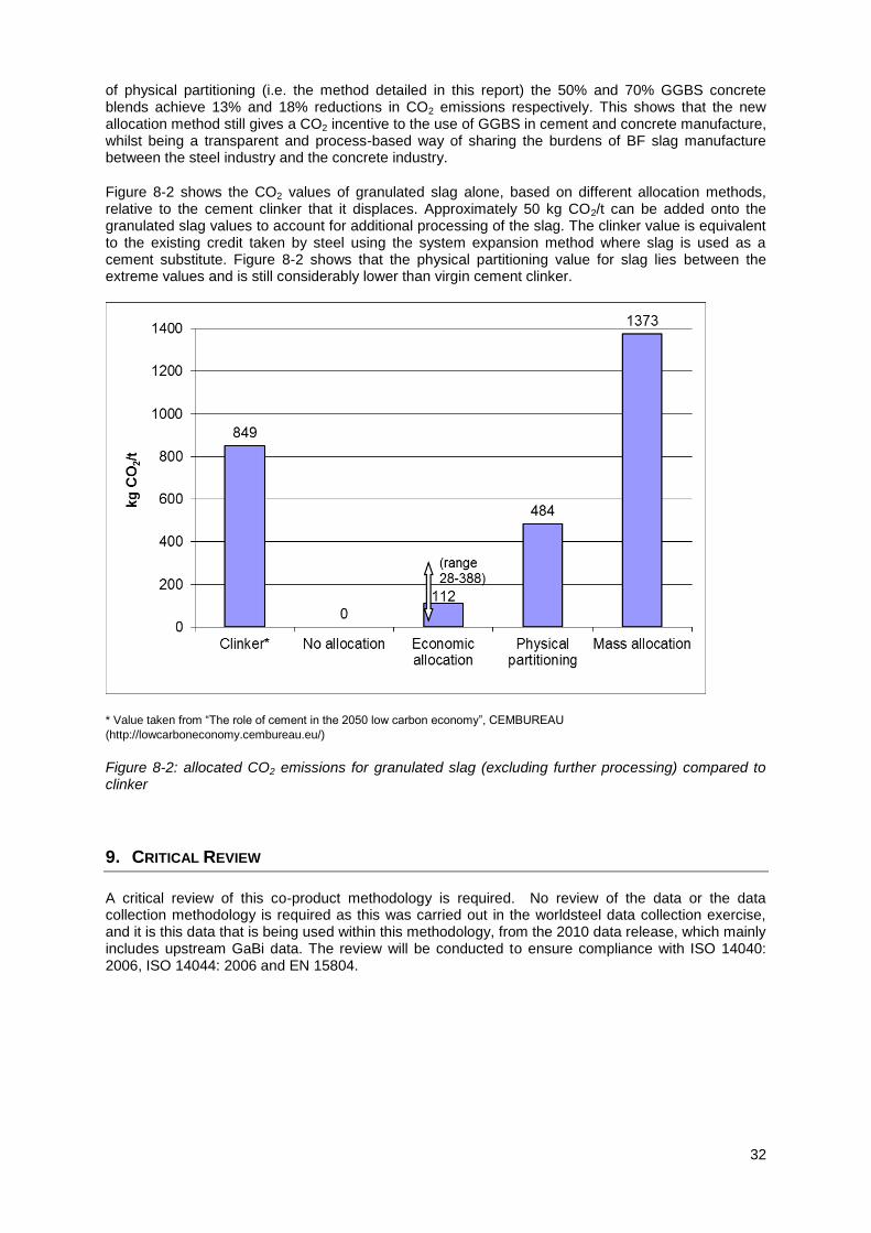
32
of physical partitioning (i.e. the method detailed in this report) the 50% and 70% GGBS concrete blends achieve 13% and 18% reductions in CO2 emissions respectively. This shows that the new allocation method still gives a CO2 incentive to the use of GGBS in cement and concrete manufacture, whilst being a transparent and process-based way of sharing the burdens of BF slag manufacture between the steel industry and the concrete industry.
Figure 8-2 shows the CO2 values of granulated slag alone, based on different allocation methods, relative to the cement clinker that it displaces. Approximately 50 kg CO2/t can be added onto the granulated slag values to account for additional processing of the slag. The clinker value is equivalent to the existing credit taken by steel using the system expansion method where slag is used as a cement substitute. Figure 8-2 shows that the physical partitioning value for slag lies between the extreme values and is still considerably lower than virgin cement clinker.
* Value taken from “The role of cement in the 2050 low carbon economy”, CEMBUREAU
(http://lowcarboneconomy.cembureau.eu/)
Figure 8-2: allocated CO2 emissions for granulated slag (excluding further processing) compared to clinker
9. CRITICAL REVIEW
A critical review of this co-product methodology is required. No review of the data or the data collection methodology is required as this was carried out in the worldsteel data collection exercise, and it is this data that is being used within this methodology, from the 2010 data release, which mainly includes upstream GaBi data. The review will be conducted to ensure compliance with ISO 14040: 2006, ISO 14044: 2006 and EN 15804.

33
Appendix 1: Operation of a Blast Furnace
The main principles of Blast Furnace operation are presented, which have been established from experimental results obtained by IRSID in the 1950s, in particular the results of vertical probing which enabled the description and location of various phenomena occurring in the reactor.
11
The blast furnace is a continuous reactor operating at steady state. It allows counter current flows of condensed phases (solids and liquids) and gases which exchange mass and energy. The analysis of these heat and oxygen transfers lead to the definition of three zones, as shown in Figure 9-1.
Solid temperature Gas temperature Iron oxidation
Figure 9-1: Blast furnace operation model
The three zones of the blast furnace can be described as follows:
An upper zone of intense heat exchange, where cold charged solids (coke and mineral burden) are quickly heated to a temperature of 950°C. As soon as the temperature reaches 450°C, the reduction of higher iron oxides (hematite and magnetite) starts.
An intermediate isothermal zone at a temperature of 950°C covering most of the stack and in which the reduction of iron oxides progresses to the level of wustite (Fe0.947O) without noticeable heat transfer. Gas and solids have the same temperature in this “Thermal reserve zone” and, if burden reducibility is sufficient, a “Chemical reserve zone” can develop. This chemical reserve zone is due to a pause of oxygen exchange due to a chemical equilibrium between gas, wustite and metallic iron germs.
A lower zone of intense heat exchange, where iron oxides coming from the thermal reserve zone are reduced to metal before melting. Pig iron and slag reach their final temperature (1500°C) while alloy elements (e.g. silicon, phosphorus, manganese) are reduced parallel to carburisation of pig iron and slag/pig iron reactions.
11 R. Nicolle - J.M. Libralesso - B. Metz Sondages dans le haut fourneau. De la mesure directe à la description des phénomènes internes. - European Blast Furnace Committee - IJmuiden 7-8/11/1990 - Rapport IRSID RE 90.022
Prep
arat
ion
zone
Mass Transfer Heat transfer
Indirect reduction:
Hematite Magnetite } Wustite
Direct reduction :
MagnetiteWustite } Iron
CO regenerationDecomposition of phosphatesReduction of non ferrous oxidesCarburisation of pig iron
Stack
GasRegeneration
Melting zone
Coke reserve
Hearth
Tuyeres
0 1.51.05
Iron oxidation O/FeHeight above tuyeres
1000 1500 20000
Temperature °C
95
0°C
Upper exchange zone
Lower exchange zone
Ther
mal
res
erve
zo
ne
Chem
ical
re
serv
e zo
ne
Proc
essi
ng z
one

34
The existence of the thermal reserve zone is due to the specific behaviour of coke which reacts with the upcoming gas to regenerate its reduction potential through the so called “Solution loss reaction”: CO2 + C 2CO. This reaction is highly endothermic and requires high temperatures to evolve with significant kinetics. The thermal reserve zone is at the temperature where this reaction starts. Metallurgical cokes react over 950°C but lower temperatures (750°C-800°C) can be observed in charcoal blast furnaces due to the higher reactivity of this material.
The existence of a zone where heat and mass transfers stop is the basis of the blast furnace model which considers a frontier in the lower part of the thermal reserve zone separating the preparation and processing zones which are described below.
Preparation zone
The preparation zone, in the upper part of the furnace, is characterised by the absence of consumption or formation of carbon by the solution-loss reaction or by carbon deposition. Excluding the gas coming from burden decomposition, the volume of reducing gases (CO+CO2 and H2+H2O) remain constant throughout this zone and there is a simple oxidation of CO to CO2 and H2 to H2O resulting from the reduction of higher iron oxides when the gas flows to the top. The presence of the CO2 and H2O indicates that the gases are always in a certain equilibrium state of oxidation.
The frontier between the preparation and processing zones is defined by the following boundary conditions:
Identical temperatures of gas and solids at the level of the thermal reserve zone;
Gas composition with a degree of oxidation corresponding to the wustite-iron equilibrium. At 950°C, this composition is as follows:
298.0COCO
COCO_XW
2
2
382.0OHH
OHH_XW
22
22
When the reducability of the burden is sufficient, iron can leave the preparation zone as pure wustite in equilibrium with the gas and a chemical reserve zone is included in the thermal reserve zone. Usually, the reduction of higher oxide is not fast enough to reach these ideal conditions and when the gas reaches this ”equilibrium composition”, the mineral burden still contains some residual magnetite which can be estimated by means of the “Deviation from ideality (Omega)” which measures an excess oxidation of iron as compared to wustite.
In the preparation zone additional reactions also occur with the burden components:
Evaporation of moisture of coke and mineral burden;
Decomposition of iron hydrates;
Decomposition of iron and calcium carbonates.
Finally, the preparation zone can be considered as recovering heat and chemical potential of the gas delivered by the processing zone. The main heat effect is heating of the burden by transfer of sensible heat from upcoming gas. The only limit is that sensible heat exceeds the requirements to keep drying potential through sufficient top gas temperature.
Processing zone
The lower part of the blast furnace is also a heat and mass exchanger and forms the basis of the model. It receives the prepared materials and processes the liquid products of the metallurgical operation, pig iron and slag. In this zone, the gasification of coke and injected reducing agents in the nozzle raceway delivers a gas composed of CO, H2 and N2 at a temperature of over 2000°C and this gas ensures the heat requirements for heating, melting and final processing of liquids. Due to its

35
reducing potential, it also allows oxygen transfer from solid or liquid oxides. Looking at the solids leaving the preparation zone, the metallurgical path is as follows:
Final reduction of iron oxides and heating of solids to melting temperature accompanied by regeneration of reducing gas through the solution loss reaction;
Melting of the solids in a zone located above the level of nozzles;
Drainage of liquids to the hearth through a coke bed (the dead man) and final heating to tapping temperature;
Separation of liquid phases in the hearth and achievement of metal/slag reactions.
Parallel to these four steps, some side reactions occur:
End of decomposition of calcium carbonate;
Decomposition of phosphates of the mineral burden;
Reduction by carbon and dissolution of alloying elements (Si, Mn, P);
Desulphurisation of pig iron by slag/metal reaction with formation of CaS;
Formation of slag by dissolution of gangue material and formation of calcium silicates.
While the gas reduction reactions have very limited heat effect, the regeneration and carbon reduction reactions require a lot of heat ahead of heating and melting requirements and the heat and mass balance of the processing zone set the operation conditions of the blast furnace.

36
Appendix 2: Overview of the BOF steelmaking process
G1 B OF ST E E L M AKI NG
Ba sic Ox y g en
Fu rn a ce
Blast F u rn ace
W et Gas De-
Du stin g (tertiary )
Slabs -B looms -B illets
M eta llu rg y
Co n tin u o u s Ca stin g
Ho t S trip M il l
Ro d an d Bar Ro ll in g
S ectio n Ro llin g
Heav y P late Ro llin g
Clarificat io n
Desu lf. - Dep h o sp h . - Desi lic. S lag s
BOF S lag
BOF Du st
Iro n Ore
S crap s
Co n tin u o u s Cast in g S calesS cales
Co n tin u o u s Cast in g S lu d g e
S team
Desu lp h u risa tio n
Dep h o sp h o ra tio n
Desil ico n isa tio n
S lu d g e
W ater
BOF Gas F in e S lu d g e
Al umi ni um
Copper
Lead
Ni ckel
Ferro Manganese
Ferro Boron
Ferro Cal ci um
Ferro Chromi um
Ferro Mol ybdeni um
Ferro Ni obi um
Ferro Phosphorous
Ferro Si l i ci um
Ferro Ti t ani um
Si l i co manganese
Unspeci fi ed
P o wer P lan t
F lare
Co k e M ak in g
Blast F u rn ace
Oth er p ro cess stag es
Ex tern al
Ox y g en M ak in g
P o wer P lan t
GasClean ed Gas
Nitro g en (N2)
Blast F u rn ace BF Gas
Co k e M ak in g COG Gas
S teamP o wer P lan t
P o wer P lan t
Air
Emissio n s
(a) Carbon Di oxi de (CO2, fossi l )
(a) Carbon Monoxi de (CO)
(a) Ni t rous Oxi des (N2O)
(a) Dust
(a) Sul phur Oxi des (SOx as SO
2)
(a) Ni t rogen Oxi d (NOx as NO
2)
(a) Zn
(a) Lead
(a) VOC
P red ecan tatio nDecan tat io n &
P u rg e T reatmen t
BOF Gas Co arse S lu d g e
S crap s
W aste W aterW aste W ater
Treatmen t P lan t
P ressu re Air
E lectrici ty (site)
Cal ci um Carbi de (CaC2)
Magnesi um (Mg)
Manganese Ore (Mn, ore)
Dol omi t e (CaCO3-MgCO3, crude)
Demin eralised W aterW ater Demin eralisin g
W aterReleased W ater
Ox y g en (O2)
Hot M etalP ig Iro n
M etall ic Ad d it iv es
In g o t Castin g
In g o ts
M o ltered Iro n S in tered Iro n
Electro d es
Oth er BF Gas
De-Du stin g s
(p rimary , d ry )
BOF Gas (1 )
BOF Gas (2 )
BOF Gas Du st
Recircu lated W ater
W aste Refracto ries
S crap s
De-Du stin g s
Ho t M etal T reatmen t Gas
Ho t M etal T reatmen t Du st
BOF S lag P ro cessin g
M etallu rg y S lu d g e
M etallu rg y Du st
M etallu rg y S lag
W ater S o ften in g S o ft W ater
W ater
L ig h t F u el Oil
Cu ttin g
Cry len e (C20
H33
NO6)
Acety len e (C2H
2)
P ro p an e
Oil
Ni t rogen (N2), Argon (Ar)
Sul phur (S)
Fl uorspar (CaF2, fl uori t e)
Carbone Di oxi de (CO2)
Sodi um Carbonat e (Na2CO3)
Sodi um Bi carbonat e (NaHCO3)
Sodi um Hydroxi de (NaOH)
Cal ci um Chl ori de (CaCl 2)
Cal ci um Sul phat e (CaSO4)
Li me (CaO)
Scal es
Iron Scraps
Synt het i c Sl ag
Recarbi di ng Agent
Pet rol eum Coke
Li qui fi ed Pet rol eum Gas
Cast i ng Powder
Refracto ries
Co k e
Co k e M ak in g
Oth er F u els
S eco n d ary BOF
Du stS eco n d ary Ded u st in g
Recircu lated W ater

37
Appendix 3: List of allocation rules applied to specific inputs and output flows in steelmaking processes
These rules have been calculated using process parameters that are typical of EU operations. Rules can be re-calculated using site specific data where available, and implemented on a site by site basis. In case of data being unavailable at site level, the default values used in this report should be used.
Note 1: BF slag as output represents the BF slag, waste for disposal. This is allocated to the hot metal.
Coke Oven Partitioning Rules
Rule
% to Coke & Coke
Oven Gas
% to Remaining Co-
products
Energy 82.9 17.1
Blast Furnace Physical Partitioning Rules
Rule % to Hot Metal % to Slag
fEHM 94.8 5.2
100% HM 100 0
100% Slag 0 100
DRI 96 4
Iron ore 88.6 11.4
Pellet 92.9 7.1
Sinter 81.7 18.3
Partitioning Rules applied to Blast Furnace Process Inputs and Outputs
BF slag 100% slag BF Slag 100% HM
BOF slag 100% slag Iron scrap 100% HM
DRI DRI Sinter / pellet Sinter
Fluorspar 100% slag All other outputs fEHM
Graded sinter Sinter
Iron ore Iron ore
Iron scrap 100% HM
Manganese 100% HM
Pellet Pellet
Scales internal 100% HM
Serpentine 100% slag
Silicon 100% HM
Sinter Sinter
Sinter / pellet dust Sinter
Soda (sodium carbonate) 100% HM
Steel scrap external 100% HM
Steel scrap home 100% HM
All other inputs fEHM
Inputs Outputs
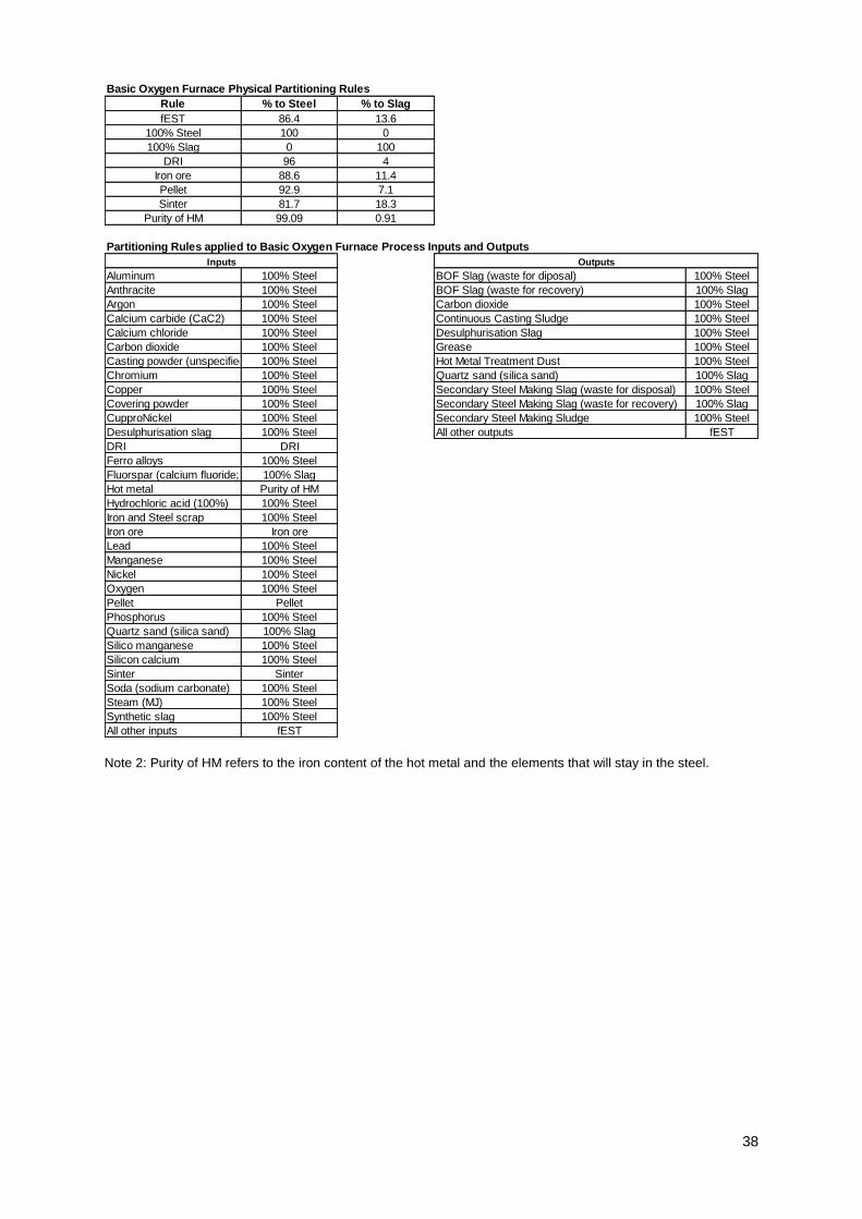
38
Note 2: Purity of HM refers to the iron content of the hot metal and the elements that will stay in the steel.
Basic Oxygen Furnace Physical Partitioning Rules
Rule % to Steel % to Slag
fEST 86.4 13.6
100% Steel 100 0
100% Slag 0 100
DRI 96 4
Iron ore 88.6 11.4
Pellet 92.9 7.1
Sinter 81.7 18.3
Purity of HM 99.09 0.91
Partitioning Rules applied to Basic Oxygen Furnace Process Inputs and Outputs
Aluminum 100% Steel BOF Slag (waste for diposal) 100% Steel
Anthracite 100% Steel BOF Slag (waste for recovery) 100% Slag
Argon 100% Steel Carbon dioxide 100% Steel
Calcium carbide (CaC2) 100% Steel Continuous Casting Sludge 100% Steel
Calcium chloride 100% Steel Desulphurisation Slag 100% Steel
Carbon dioxide 100% Steel Grease 100% Steel
Casting powder (unspecified) 100% Steel Hot Metal Treatment Dust 100% Steel
Chromium 100% Steel Quartz sand (silica sand) 100% Slag
Copper 100% Steel Secondary Steel Making Slag (waste for disposal) 100% Steel
Covering powder 100% Steel Secondary Steel Making Slag (waste for recovery) 100% Slag
CupproNickel 100% Steel Secondary Steel Making Sludge 100% Steel
Desulphurisation slag 100% Steel All other outputs fEST
DRI DRI
Ferro alloys 100% Steel
Fluorspar (calcium fluoride; fluorite)100% Slag
Hot metal Purity of HM
Hydrochloric acid (100%) 100% Steel
Iron and Steel scrap 100% Steel
Iron ore Iron ore
Lead 100% Steel
Manganese 100% Steel
Nickel 100% Steel
Oxygen 100% Steel
Pellet Pellet
Phosphorus 100% Steel
Quartz sand (silica sand) 100% Slag
Silico manganese 100% Steel
Silicon calcium 100% Steel
Sinter Sinter
Soda (sodium carbonate) 100% Steel
Steam (MJ) 100% Steel
Synthetic slag 100% Steel
All other inputs fEST
Inputs Outputs