
A Method of Reducing Disturbances in Radio Signals by a System of Frequency Modulation

PROCEEDINGS OF
V OLUME 2 4 May, 1936 N U M B E R 5
Board of EditorsALFRED N. GOLDSMITH, Chairman
R. R. BATCHER K. S. VAN DYKEH. H. BEVERAGEF. W. GROVER
H. P. WESTMAN, ex officioL. P. WHEELER
J. W. HORTON L. E. WHITTEMOREG. W. PICKARD WILLIAM WILSON
CONTENTS
PART I
Condensed Program of Eleventh Annual Convention. . . . . . . . . . . . . . ..Cover II
Frontispiece, Hotel Statler, Convention Headquarters. . . . . . . . . . . . . . . .. 670
Institute News and Radio Notes . . . . . . . . . . . . . . . . . . . . . . . . . . . . . . . . . . .. 671
Eleventh Annual Convention.. . . . . . . . . . . . . . . . . . . . . . . . . . . . . . . 671
PART II
A Method of Reducing Disturbances in Radio Signaling by a System ofFrequency Modulation . . . . . . . . . . . . . . . . . . . . . . EDWIN H. ARMSTRONG 689
Television in Germany . . . . . . . . . . . . . . . . . . . . . . . . . . . . ..H UBERT GIBAS 741
A New System for Blind Landing of Airplanes. . . . . . . . . . . . . . . . . . . . . . . .. . . . . . . . . . . . . . . . . . . . . . . . . . . . . . . . . .K. BAUMANN AND A. ETTINGER 751
An Urban Field Strength Survey at Thirty and One Hundred Megacycles. . . . . . . . . . . . . . . . . . . . . . . . . . . . . . R. S. H OLMES AND A. H. TURNER 755
A New Method of Modulating the Magnetron Oscillator . . . . . . . . . . . . . . .. . . . . . . . . . . . . . . . . . . . J A N U S Z GROSZKOWSKI AND S T A N I S L A W R Y Z K O 771
Effective Resistance of Closed Antennas. . . . . . . . . . . . . . . . . . . . . . . . . . . . . .. . . . . . . . . . . . . . . . . . . . ..V. I. B ASHENOFF AND N. A. MJASOEDOFP 778
A Study of the Electromagnetic Field in the Vicinity of a Radiator. . . . . .. . . . . . . . . . . . . . . . . . . . . . . . . . . . . . . . . . . . . . . . . . . . . . .. F. R. S T A N S E L 802
Book Reviews: “Your Invention-How to Protect and Merchandise It,”by E. B. Lyford . . . . . . . . . . . . . . . . . . . . . . . . . . . . .. H. H. BEVERAGE 811
“Perpetual Trouble Shooter’s Manual-Volume VI,” by J. F. Rider. . . . . . . . . . . . . . . . . . . . . . . . . . . . . . . . . . . . . . . . . . . . . . . . . . C. E. DEAN 812
Contributors to This Issue . . . . . . . . . . . . . . . . . . . . . . . . . . . . . . . . . . . . . . . . . 813
Copyright, 1936, by The Institute of Radio Engineers, Inc.,

Proceedings of the Institute of Radio EngineersVolume 24, Number 5
TECHNICAL PAPERS
May, 1936
A METHOD OF REDUCING DISTURBANCES INRADIO SIGNALING BY A SYSTEM OF
FREQUENCY MODULATION*
B Y
E DWIN H. AR M S T R O N G
(Department of Electrical Engineering, Columbia University, New York City)
Summary-A new method of reducing the effects of all kinds of disturbancesis described. The transmitting and receiving arrangements of the system, which makesuse of frequency modulation, are shown in detail. The theory of the process bywhich noise reduction is obtained is discussed and an account is given of the practicalrealization of it in transmissions during the past year from the National Broad-casting Company’s experimental station on the Empire State Building in New YorkCity to Westhampton, Long Island, and Haddonfield, New Jersey. Finally, meth-ods of multiplexing and the results obtained in these tests are reported.
PART I
T IS the purpose of this paper to describe some recent develop-ments in the art of transmitting and receiving intelligence by themodulation of the frequency of the transmitted wave. It is the
further purpose of the paper to describe a new method of reducinginterference in radio signaling and to show how these developmentsmay be utilized to produce a very great reduction in the effects of thevarious disturbances to which radio signaling is subject.
H I S T O R I C A L
The subject of frequency modulation is a very old one. While thereare some vague suggestions of an earlier date, it appears to have hadits origin shortly after the invention of the Poulsen arc, when the in-ability to key the arc in accordance with the practice of the sparktransmitter forced a new method of modulation into existence. The ex-pedient of signaling (telegraphically) by altering the frequency of thetransmitter and utilizing the selectivity of the receiver to separatethe signaling wave from the idle wave led to the proposal to apply theprinciple to telephony. It was proposed to effect this at the transmitterby varying the wave length in accordance with the modulations of thevoice, and the proposals ranged from the use of an electrostatic micro-
* Decimal classification: R400 X R430. Original manuscript received by theInstitute, January 15, 1936. Presented before New York meeting, November 6,1935.
689

690 Armstrong: Frequency Modulation-Noise Reduction
phone associated with the oscillating circuit to the use of an inductancetherein whose value could be controlled by some electromagneticmeans. At the receiver it was proposed to cause the variations in fre-quency of the received wave to create amplitude variations by the useof mistuned receiving circuits so that as the incoming variable fre-quency current came closer into or receded farther from the resonantfrequency of the receiver circuits, the amplitude of the currents thereinwould be correspondingly varied and so could be detected by the usualrectifying means. No practical success came from these proposals andamplitude modulation remained the accepted method of modulatingthe arc. The various arrangements which were tried will be found in thepatent records of the times and subsequently in some of the leadingtextbooks.1 The textbooks testify unanimously to the superiority ofamplitude modulation.
Some time after the introduction of the vacuum tube oscillatorattempts were again made to modulate the frequency and again theverdict of the art was rendered against the method. A new elementhowever, had entered into the objective of the experiments. The quan-titative relation between the width of the band of frequencies requiredin amplitude modulation and the frequency of the modulating currentbeing now well understood, it was proposed to narrow this band by theuse of frequency modulation in which the deviation of the frequencywas to be held below some low limit; for example, a fraction of thehighest frequency of the modulating current. By this means aneconomy in the use of the frequency spectrum was to be obtained. Thefallacy of this was exposed by Carson2 in 1922 in the first mathematicaltreatment of the problem, wherein it was shown that the width of theband required was at least double the value of the highest modulatingfrequency. The subject of frequency modulation seemed foreverclosed with Carson’s final judgment, rendered after a thorough con-sideration of the matter, that “Consequently this method of modula-tion inherently distorts without any compensating advantages what-soever. ”
Following Carson a number of years later the subject was againexamined in a number of mathematical treatments by writers whoseresults concerning the width of the band which was required confirmedthose arrived at by Carson, and whose conclusions, when any were ex-pressed, were uniformly adverse to frequency modulation.
1 Zenneck, “Lehrbuch der drahtlosen Telegraphy, ” (1912).Eccles, “Wireless Telegraphy and Telephony,” (1916).Goldsmith, “Radio Telephony,” (1918).
2 “Notes on the theory of modulation,”February, (1922).
PR O C . I.R.E., vol. 10, pp. 57-82;

Armstrong: Frequency Modulation-Noise Reduction 691
In 1929 Roder3 confirmed the results of Carson and commentedadversely on the use of frequency modulation.
In 1930 van der Pol4 treated the subject and reduced his resultsto an excellent form for use by the engineer. He drew no conclusionsregarding the utility of the method.
In 1931, in a mathematical treatment of amplitude, phase, and fre-quency modulation, taking into account the practical aspect of the in-crease of efficiency at the transmitter which is possible when the fre-quency is modulated, Roder5 concluded that the advantages gainedover amplitude modulation at that point were lost in the receiver.
In 1932 Andrew6 compared the effectiveness of receivers for fre-quency modulated signals with amplitude modulated ones and arrivedat the conclusion that with the tuned circuit method of translating thevariations in frequency into amplitude variations, the frequency modu-lated signal produced less than one tenth the power of one which wasamplitude modulated.
While the consensus based on academic treatment of the problemis thus heavily against the use of frequency modulation it is to the fieldof practical application that one must go to realize the full extent ofthe difficulties peculiar to this type of signaling.
The conditions which must be fulfilled to place a frequency modula-tion system upon a comparative basis with an amplitude modulatedone are the following:
1. It is essential that the frequency deviation shall be about a fixedpoint. That is, during modulation there shall be a symmetrical changein frequency with respect to this point and over periods of time thereshall be no drift from it.
2. The frequency deviation of the transmitted wave should be in-dependent of the frequency of the modulating current and directlyproportional to the amplitude of that current.
3. The receiving system must have such characteristics that it re-sponds only to changes in frequency and that for the maximum changeof frequency at the transmitter (full modulation) the selective character-istic of the system responsive to frequency changes shall be such that sub-stantially complete modulation of the current therein will be produced.
3 “Ueber Frequenemodulation,”4 “Frequency modulation,”
Telefunken-Zeitung no. 53, p. 48, (1929).
(1930).PROC. I.R.E., vol. 18, pp. 1194-1205; July,
5 “Amplitude, phase, and frequency modulation,” PROC. I.R.E., vol. 19, pp.2145-2176; December, (1931).
6 “The reception of frequency modulated radio signals;” PROC. I.R.E.,vol. 20, pp. 835-840; May, (1932).

692 Armstrong: Frequency Modulation-Noise Reduction
4. The amplitude of the rectified or detected current should bedirectly proportional to the change in frequency of the transmittedwave and independent of the rate of change thereof.
5. All the foregoing operations should be carried out by the use ofaperiodic means.
THE TRANSMITTING SY S T E M
An extensive experience with the various known methods of modu-lating the frequency convinced the writer as indeed it would anyonewho has tried to work with this method of modulation at a high fre-quency that some new system must be evolved. During the course ofthis work there was evolved a method which, it is believed, is a com-plete solution of the transmitter problem. It consists in employing themodulating current to shift the phase of a current derived from asource of fixed phase and frequency by an amount which is directlyproportional to the amplitude of the modulating current and inverselyproportional to its frequency. The resulting phase shift is then putthrough a sufficient number of frequency multiplications to insure 100per cent modulation for the highest frequency of the modulating cur-rent. By keeping the initial phase shift below thirty degrees sub-stantial linearity can be obtained.
The means employed to produce the phase shift consisted of asource of fixed frequency, a balanced modulator excited by this source,and arrangements for selecting the side frequencies from the modula-tor output and combining them in the proper phase with an unmodu-lated current derived from the initial source. The phase relationswhich must exist where the combination of the modulated and un-modulated currents takes place are that at the moment the upper andlower side frequencies produced by the balanced modulator are inphase with each other, the phase of the current of the master oscillatorfrequency with which they are combined shall differ therefrom byninety degrees.
The schematic and diagrammatic arrangements of the circuits maybe visualized by reference to Figs. 1 and 2, and their operation under-stood from the following explanation. The master oscillator shown inthese diagrams may be of the order of fifty to one hundred thousand ormore cycles per second, depending upon the frequency of the modulat-ing current. An electromotive force derived from this oscillator isapplied in like phase to the grid of an amplifier and both grids of a bal-anced modulator. The plate circuits of the modulator tubes are madenonreactive for the frequency applied to their grids by balancing outthe reactance of the transformer primaries as shown. The plate cur-

Armstrong: Frequency Modulation-Noise Reduction 693
rents are therefore in phase with the electromotive force applied to thegrid. The succeeding amplifier is coupled to the output transformer bya coil whose natural period is high compared to the frequency of themaster oscillator and the electromotive force applied to the grid of thisamplifier when the modulator tubes are unbalanced by a modulatingvoltage applied to the screen grids is therefore shifted in phase ninety
AmplifierI E
90o PhaseBalanced C h a n g i n g Side BandModulator Device Amp lifier
CorrectionAmplifier
To
Fig. 1
degrees (or 270 degrees) with respect to the phase of the electromotiveforce applied to the grids of the balanced modulators. Hence it followsthat the phase of the currents existing in the plate circuit of the ampli-fier of the output of the balanced modulator (at the peak of the modu-lation voltage) is either ninety degrees or 270 degrees apart from thephase of the current existing in the plate circuit of the amplifier of the
Master
Balanced
Amplifier
ModulationInput
Fig. 2
unmodulated master oscillator current. Therefore the voltages whichthey develop across the common resistance load will be ninetv degreesapart.
The resulting effect on the phase of the voltage developed across theresistance in the plate circuits of these two amplifiers when modulationis applied, compared to the phase of the voltage which would existthere in the absence of modulation will appear from Fig. 3. It will beobserved from the vector diagrams that the phase of the voltage across

694 Armstrong: Frequency Modulation-Noise Reduction
the common resistance load is alternately advanced and retarded bythe combination of the modulated and unmodulated components andthat the maximum phase shift is given by an angle whose tangent isthe sum of the peak values of the two side frequencies divided by thepeak value of the unmodulated component. By keeping this angle
Voltage (E .M.F applied to Modulatorr Grids
Unmodulated R. F.
Fig. 3
sufficiently small (not greater than thirty degrees) it may be madesubstantially proportional to the amplitude of the two side frequenciesand hence to the amplitude of the initial modulating current.7 It willbe observed that if the angle through which the phase is shifted be thesame for all frequencies of modulation then the rate of increase or de-
Fig. 4
crease of the angle will be proportional to the frequency of modulationand hence the deviation in frequency of the transmitted wave will beproportional to the frequency of the modulating current. In order toinsure a frequency deviation which is independent of the modulation
7 For the large angular displacements there will be an appreciable change inamplitude of the combined currents at double the frequency of the modulatingcurrent. This variation in amplitude is not of primary importance and is re-moved subsequently by a limiting process.

Armstrong: Frequency Modulation-Noise Reduction 695
frequency it is necessary that, for a constant impressed modulatingelectromotive force, the angle through which the phase is shiftedbe made inversely proportional to the frequency of the modulatingcurrent. This is accomplished by making the amplification of the in-put amplifier inversely proportional to frequency by means of the cor-rection network shown in Fig. 4. The network consists of a high re-sistance in series with a capacity whose impedence for the lowest fre-quency of modulation is relatively small with respect to the series re-sistance. The voltage developed across the capacity which excites thesucceeding amplifier stage is therefore inversely proportional to fre-quency and hence it follows that the angle through which the currentis, advanced or retarded becomes directly proportional to the ampli-tude of the modulating current and inversely proportional to its fre-quency. The resulting phase shift must be multiplied a great manytimes before a frequency modulated current which can be usefully em-ployed is produced. This will be clear from an examination of the re-quirements of a circuit over which it is desired to transmit a frequencyrange from thirty to 10,000 cycles. Since the lowest frequency is limitedto a phase shift of thirty degrees it follows that for 10,000 cycles thephase shift will be but 0.09 degree. The minimum phase shift for 100per cent modulation of the transmitted wave is roughly forty-five de-grees. A frequency multiplication of 500 times is required, therefore, toproduce a wave which is fully modulated8 and capable of being effec-tively handled by the receiver in the presence of disturbing currents.
Under ordinary conditions this multiplication of frequency can berealized without loss of linearity by a series of doublers and triplersoperated at saturation provided the correct linkage circuits betweenthe tubes are employed. Where however the wide band frequencyswing which will be described subsequently in this paper is employedunexpected difficulties arise. These also will be dealt with subsequently.
From the foregoing description it will be seen that this method ofobtaining frequency modulation consists in producing initially phasemodulation in which the phase shift is inversely proportional to thefrequency of modulation and converting the phase modulated currentinto a frequency modulated one by successive multiplications of thephase shift. The frequency stability, of course, is the stability attain-able by a crystal controlled oscillator and the symmetry of the devia-tion may be made substantially perfect by compensating such asym-metrical action in the system as may occur. With the method of phase
8 One in which the side frequencies are sufficiently large with respect to the
carrier to make it possible to produce at the receiver 100 per cent modulationin amplitude, without the use of expedients which affect unfavorably the signal-to-noise ratio.

696 Armstrong: Frequency Modulation-Noise Reduction
shifting shown in Fig. 2 there is an asymmetry which is of importancewhen the frequency of modulation is high compared to the masteroscillator frequency. It occurs in the plate transformer of the balancedmodulator. The plate circuits of these tubes are substantially aperiodicand consequently the amplitudes of the upper and lower side fre-quencies are approximately equal and from this it follows that theelectromotive forces induced in the secondary are directly propor-tional to the values of these frequencies. Where the master oscillatorfrequency is 50,000 cycles and a frequency of modulation of 10,000cycles is applied, the upper side frequency may be fifty per cent greaterthan the lower. This inequality may be compensated by a resistance-capacity network introduced subsequent to the point at which thecombination of carrier and side frequencies is effected but prior to anypoint at which loss of linearity of amplitude occurs. The level in theamplifiers ahead of the compensating network must be kept sufficientlylow so that the operation of the system is linear. After the side fre-quencies are equalized amplitude linearity ceases to be of importance.
The performance of transmitters operating on this principle hasbeen in complete accord with expectations. While the arrangementsmay seem complex and require a large amount of apparatus the com-plexity is merely that of design, not of operation. The complete ar-rangement, up to the last few multiplifier stages may be carried outmost effectively with receiving type tubes, these last multiplier stagesconsisting of power type pentodes for raising the level to that neces-sary to excite the usual power amplifiers.
THE RECEIVING SYSTEM
The most difficult operation in the receiving system is the transla-tion of the changes in the frequency of the received signal into a current which is a reproduction of the original modulating current.This is particularly true in the case of the transmission of high fidelitybroadcasting. It is, of course, essential that the translation be madelinearly to prevent the generation of harmonics but it must also beaccomplished in such a manner that the signaling current is not placedat a disadvantage with respect to the various types of disturbances towhich radio reception is subject. In the particular type of translationdeveloped for this purpose which employs the method of causing thechanges in frequency to effect changes in amplitude which are thenrectified by linear detectors, it is essential that for the maximum devia-tion of the transmitted frequency there shall be a substantial amplitudemodulation of the received wave. At first sight it might appear that100 per cent or complete modulation would be the ideal, but there are

Armstrong: Frequency Modulation-Noise Reduction 697
objections to approachin g this limit too closely. It will, however, beclear that where the translation is such that only a few per centamplitude modulation results from the maximum deviation of the fre-quency of the transmitted wave the receiver is hopelessly handicappedwith respect t o amplitude disturbances. This is true because even whenthe level of the voltage applied to the conversion system is kept con-stant by a current limiting device or automatic volume control therestill remains those intervals wherein the incoming disturbances arrivein the proper phase to neutralize the signaling current in the detector,effecting thereby substantially complete modulation of the rectifiedcurrent or the intervals wherein the disturbing currents themselveseffect greater amplitude changes than the signal itself by cross modula-tion of its frequency.
Fig. 5
An arrangement in which linear conversion can be effected withouthandicapping the system with respect to amplitude disturbances isillustrated diagrammatically in Fig. 5. Two branch circuits each con-taining resistance, capacity, and inductance in series as shown are con-nected to the intermediate-frequency amplifier of a superheterodyneat some suitable frequency. One capacity and inductance combinationis made nonreactive for one extreme of the frequency band which thesignal current traverses and the other capacity and inductance com-bination is made nonreactive for the other end of the band. The resist-ances are chosen sufficiently high to maintain the current constant overthe frequency range of the band; in fact, sufficiently high to make eachbranch substantially aperiodic. The reactance characteristics takenacross each capacity and inductance combination will be as illustratedin Fig. 6 by curves A and B. Since the resistances in series with thereactance combinations are sufficient to keep the current constantthroughout the frequency band it follows that the voltages developedacross each of the two combinations will be proportional to their re-actances as is illustrated in curves A’ and B’. The two voltages are
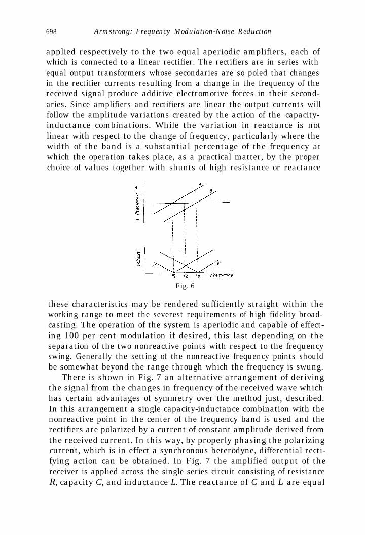
698 Armstrong: Frequency Modulation-Noise Reduction
applied respectively to the two equal aperiodic amplifiers, each ofwhich is connected to a linear rectifier. The rectifiers are in series withequal output transformers whose secondaries are so poled that changesin the rectifier currents resulting from a change in the frequency of thereceived signal produce additive electromotive forces in their second-aries. Since amplifiers and rectifiers are linear the output currents willfollow the amplitude variations created by the action of the capacity-inductance combinations. While the variation in reactance is notlinear with respect to the change of frequency, particularly where thewidth of the band is a substantial percentage of the frequency atwhich the operation takes place, as a practical matter, by the properchoice of values together with shunts of high resistance or reactance
Fig. 6
these characteristics may be rendered sufficiently straight within theworking range to meet the severest requirements of high fidelity broad-casting. The operation of the system is aperiodic and capable of effect-ing 100 per cent modulation if desired, this last depending on theseparation of the two nonreactive points with respect to the frequencyswing. Generally the setting of the nonreactive frequency points shouldbe somewhat beyond the range through which the frequency is swung.
There is shown in Fig. 7 an alternative arrangement of derivingthe signal from the changes in frequency of the received wave whichhas certain advantages of symmetry over the method just, described.In this arrangement a single capacity-inductance combination with thenonreactive point in the center of the frequency band is used and therectifiers are polarized by a current of constant amplitude derived fromthe received current. In this way, by properly phasing the polarizingcurrent, which is in effect a synchronous heterodyne, differential recti-fying action can be obtained. In Fig. 7 the amplified output of thereceiver is applied across the single series circuit consisting of resistanceR, capacity C, and inductance L. The reactance of C and L are equal

Armstrong: Frequency Modulation-Noise Reduction 699
for the mid-frequency point of the band and the reactance curve isas illustrated in A of Fig. 8. At frequencies above the nonreactive
Fig. 7
point the combination acts as an inductance; at frequencies below thenonreactive point as a capacity and the phase of the voltage de-veloped across the combination with respect to the current through it
Combined Current
F1 F F2< Working Range > frequency
Fig. 8
differs, therefore, by 180 degrees above and below the nonreactivepoint. Since the current through the circuit is maintained constant overthe working range by the resistance R and since the resistance of the

700 Armstrong: Frequency Modulation--Noise Reduction
capacity C and inductance L may be made very low the electromotiveforce developed across C and L is of the form shown in curve B. Thiscurve likewise represents the variation in voltage with variation in fre-quency which is applied to the grids of the amplifiers and eventuallyto the two rectifiers D1 and D2.
The heterodyning or polarizing voltage is obtained by taking thedrop across the resistance R1, amplifying it, changing its phase throughninety degrees and applying the amplified voltage to the screen gridsof the amplifiers in opposite phase. The characteristic of this amplify-ing and phase changing system must be flat over the working range.Under these conditions the signaling and heterodyning voltages areexactly in phase in one rectifier and 180 degrees out of “phase in theother, and hence for a variable signaling frequency the rectifying char-acteristics are as shown in curves C and D the detector outputs beingcumulatively combined for frequency changes. Adjustment of the rela-tive amplitudes of the signaling and polarizing voltages in the rectifiercontrols the degree of amplitude modulation produced from 100 per centdown to any desired value.
PART II
With the foregoing description of the instrumentalities for trans-mitting and receiving frequency modulated waves it is now in orderto consider the main object of the paper; the method of reducing dis-turbances and the practical results obtained by its use.
M ETHOD OF R EDUCING D I S T U R B A N C E S
The basis of the method consists in introducing into the transmittedwave a characteristic which cannot be reproduced in disturbances ofnatural origin and utilizing a receiving means which is substantially notresponsive to the currents resulting from the ordinary types of dis-turbances and fully responsive only to the type of wave which has thespecial characteristic.
The method to be described utilizes a new principle in radio signal-ing the application of which furnishes an interesting conflict with onewhich has been a guide in the art for many years; i.e., the belief thatthe narrower the band of transmission the better the signal-to-noiseratio. That principle is not of general application. In the presentmethod an opposite rule applies.
It appears that the origin of the belief that the energy of the dis-turbance created in a receiving system by random interference de-pended on the band width goes back almost to the beginning of radio.In the days of spark telegraphy it was observed that “loose cou-pling” of the conventional transmitter and receiver circuits produced

Armstrong: Frequency Modulation-Noise Reduction 701
a “sharper wave” and that interference from lightning discharges, theprinciple “static” of those days of insensitive and nonamplifying re-ceivers was decreased. Further reduction in interference of this sortoccurred when continuous-wave transmitters displaced the spark andwhen regeneration narrowed the band width of the receiving system.It was observed, however, that “excessive resonance” must not beemployed either in telegraphic or more particularly in telephonic sig-naling or the keying and speech would become distorted. It was con-cluded in a qualitative way that there was a certain “selectivity”which gave the best results.
In 1925 the matter was placed on a quantitative basis by Carson 9
where in a mathematical treatment of the behavior of selective cir-cuits when subjected to irregular and random interference (with par-ticular reference to “static”), on the basis of certain assumptions, theproposition was established that “if the signaling system requires thetransmission of the band of frequencies corresponding to the intervalw2 -w1 and if the selective circuit is efficiently designed to this end, thenthe mean square interference current is proportional to the frequencyband width (w2 - 4 /27r.
Hazeltinel0 pointed out that when a detector was added to such asystem and a carrier of greater level than the interference currents waspresent, that for aural reception only those components of the inter-fering current lying within audible range of the carrier frequency wereof importance and that Carson’s theory should be supplemented by theuse of a factor equal to the relative sensitivity of the ear at differentfrequencies.
With the discovery of shot effect and thermal agitation noises andthe study of their effect on the limit of amplification quantitative rela-tions akin to those enunciated by Carson with respect to static werefound to exist.
Johnson, 11 reporting the discovery of the electromotive force dueto thermal agitation and considering the problem of reducing the noisein amplifiers caused thereby, points out that for this type of disturb-ance the theory indicates, as in the Carson theory, that the frequencyrange of the system should be made no greater than is essential for theproper transmission of the applied input voltage, that where a voltageof constant frequency and amplitude is used one may go to extremes in
9 J. R. Carson, “Selective circuits and static interference,” Bell Sys. Tech.Jour., vol. 4, p. 265, (1925).
10 L. A. Hazeltine, Discussion on “The shielded neutrodyne receiver,”PROC. I.R.E., vol. 14, pp. 408, 409; June, (1926).
11 J. B. Johnson, “Thermal agitatioq of electricity in conductors, Phys. Rev.,vol. 32, no. 1, July, (1926).

702 Armstrong: Frequency Modulation--Noise Reduction
making the system selective and thereby proportionately reducing thenoise, but that when the applied voltage varies in frequency or ampli-tude the system must have a frequency range which takes care of thesevariations and the presence of a certain amount of noise must be ac-cepted.
Ballantine12 in a classical paper discussing the random interferencecreated in radio receivers by shot and thermal effects obtained a com-plete expression for the noise output.13
Johnson and Llewellyn, 14 in a paper dealing generally with thelimits to amplification, point out that in a properly designed amplifierthe limit resides in thermal agitation in the input circuit to the ampli-fier, that the power of the disturbance in the output of the amplifieris proportional to its frequency range and that this, the only controlla-ble factor in the noise equation, should be no greater than is needed forthe transmission of the signal. A similar conclusion is reached in thecase of a detector connected to the output of a radio-frequency ampli-fier and supplied with a signal carrier.
It is now of interest to consider what happens in a linear detectorconnected to the output of a wide band amplifier which amplifiesuniformly the range from 300 to 500 kilocycles. Assume that theamplification be sufficiently great to raise the voltage due to thermalagitation and shot effect to a point sufficient to produce straight-linerectification and that no signal is being received. Under these condi-tions the frequencies from all parts of the spectrum between 300 and500 kilocycles beat together to contribute in the output of the detec-tor to the rough hissing tone with which the art is familiar. The spec-trum of frequencies in the rectified output runs from some very lowvalue which is due to adjacent components throughout the rangebeating with one another to the high value of 200 kilocycles causedby the interferences of the extremes of the band.
It is important to note that all parts of the 300- to 500-kilocyclespectrum contribute to the production in the detector output of thosefrequencies with which we are particularly interested-those lyingwithin the audible range.
l2 Stuart Ballantine, “Fluctuation noise in radio receivers,” PROC. I.R.E.,vol. 18, pp. 1377-1387; August, (1930).
l3 Ballantine expressed his result as follows: “In a radio receiver employinga square-law detector and with a carrier voltage impressed upon the detector,the audio-frequency noise, as measured by an instrument indicating the averagevalue of the square of the voltage (or current), is proportional to the area underthe curve representing the square of the over-all transimpedance (or of thetransmission) from the radio-frequency branch in which the disturbance origi-nates to the measuring instrument as a function of frequency and proportionalto the square of the carrier voltage. ”
14 J. B. Johnson and F. B. Llewellyn, “Limits t o amplification,” Trans.A.I.E.E., vol. 53, rio. 11, November, (1934).

Armstrong: Frequency Modulation-Noise Reduction 703
Assume now that an unmodulated signal carrier is received of, forexample, 400 kilocycles and that its amplitude is greater than that ofthe disturbing currents. Under these circumstances an entirely new setof conditions arise. The presence of the 400-kilocycle current stops therectification of the beats which occur between the various componentsof the spectrum within the 300- to 500-kilocycle band and forces al lrectification to take place in conjunction with the 400-kilocycle carrier.Hence in the output of the rectifier there is produced a series of fre-quencies running from some low value up to 100 kilocycles. The lowestfrequency is produced by those components of the spectrum which lieadjacent to the 400-kilocycle current, the highest by those frequen-cies15,16 which lie at the extremity of the band; i.e., 300 and 500 kilo-cycles, respectively.
0<
I 1 1 ! I ’ 1 I I I 11 2 3 4 5 6 7 8 9 l0
*Ratio of Peak Value of 400 K.C. Current to PeakValue of Combined 350 and 351 KC. Currents
Fig. 9
The characteristics of the rectifiers and the magnitude of some ofthe effects involved in the above-described action may be visualized byreference to the succeeding figures. The actual demodulation of thebeats occurring between adjacent frequency components by the pres-ence of the 400-kilocycle current is shown by the characteristic of Fig.9, which illustrates what happens to the output voltage of a rectifierproduced by beating together two equal currents of 350 and 351 kilo-cycles, respectively, when a 400-kilocycle current is introduced in thesame rectifier and its amplitude progressively increased with respect
I5 It has been pointed out by Ballantine16 that it is improper to speak of theamplitude of a single component of definite frequency and that the proper unitis the noise per frequency interval. This is, of course, correct, but to facilitatethe physical conception of what occurs in this system the liberty is taken ofreferring to the noise components as though they were of continuous sine waveform. The behavior of the system may be checked by actually introducing froma local generator such components.
l6 “Fluctuation noise in radio receivers,” PROC. I.R.E., vol. 18, pp. 1377-1387; August, (1930).

704 Armstrong: Frequency Modulation-Noise Reduction
to the amplitude of these two currents. The characteristic was obtainedwith the arrangement shown in Fig. 10, in which two oscillators of 350and 351 kilocycles produced currents of equal strength in a linearrectifier, this rectifier consisting of a diode in series with 10,000 ohmsresistance. The output of the rectifier is put through a low-pass filter,a voltage divider, and an amplifier. The 400-kilocycle current is intro-
Fig. 10
duced into the rectifier without disturbing the voltage relations of theother two oscillators and the effect on the rectified output voltage ob-served as the 400-kilocycle current is increased. The purpose of thelow-pass filter is to prevent the indicating instrument from respondingto the 49- or 50-kilocycle currents produced by the interaction of the350- and 351-kilocycle currents with the current of 400 kilocycles. The
Fig. 11
linearity characteristic of the rectifier is shown in Fig. 11 where thevoltage produced by the beats between a current of constant amplitudeand one whose amplitude is raised from equality with, to many timesthe value of, the first current is plotted against the ratio of the two.The linearity of the rectifier is such that after the ratio of the currentbecomes two to one no further increase, in rectifier output voltageresults. In fact with the levels used in these measurements when the

Armstrong: Frequency Modulation-Noise Reduction 705
two currents are equal there is an efficiency of rectification of onlyabout twenty per cent less than the maximum obtained.
It is important to note here that the only frequencies in the spec-trum which contribute to the production of currents of audible fre-quency in the detector output circuit are those lying within audiblerange of the signal carrier. We may assume this range as roughly from390 to 410 kilocycles. The frequencies lying beyond these limits beatagainst the 400-kilocycle carrier and of course are rectified by thedetector but the rectified currents which are produced are of fre-quencies which lie beyond the audible range and produce therefore noeffect which is apparent to the ear. It follows that if the signal carrieris somewhat greater in amplitude than the disturbing currents thesignal-to-noise ratio for a receiver whose band of admittance coverstwice the audible range will be the same as for one whose band widthis many times that value. (There are, of course, certain second ordereffects, but they are of such minor importance that the ear cannot de-tect them.) The amplitude of the disturbances in the detector output,will vary in accordance as the components of the disturbing currentscome into or out of phase with the signal carrier, the rectified or de-tector output current increasing above and decreasing below the levelof the rectified carrier current by an amount proportional to theamplitude of the components of the 300-500-kilocycle band. The rea-sons for the independence of the signal-to-noise ratio of the band widthunder the circumstances which have been described should now beapparent. In any event, it can be readily demonstrated experimentally.
It is now in order to consider what happens when a current limit-ing device is introduced between the output of the amplifier and thedetector input. (Assume signal level still above peak noise level.)Two effects will occur. One of the effects will be to suppress in theoutput circuit of the limiter all components of the disturbing currentswhich are in phase with, or opposite in phase to, the 400-kilocycle car-rier. The other effect will be to permit the passage of all components ofthe disturbing currents which are in quadrature with the 400-kilocyclecurrent.
Both the above effects are brought about by a curious processwhich takes place in the limiter. Each component within the bandcreates an image lying on the opposite side of the 400-kilocycle pointwhose frequency difference from the 400-kilocycle current is equalto the frequency difference between that current and the original com-ponent. The relative phase of the original current in question, the400-kilocycle current and the image current is that of phase modula-tion-that is, at the instant when the original component and its

706 Armstrong: Frequency Modulation-Noise Reduction
image are in phase with each other, the 400-kilocycle current will be inquadrature with them both and at the instant that the 400-kilocyclecurrent is in phase with one of these two frequencies, it will be out ofphase with the other.
The relation (obtained experimentally) between the amplitudes ofthe original current and the image is illustrated by the curve of Fig. 12,
Fig. 12
which shows the relation between the amplitude of a 390-kilocycle cur-rent introduced into a limiter along with the 400-kilocycle current andthe resulting 410-kilocycle image in terms of percentage amplitude ofthe 400-kilocycle current. It will be obvious from the curve that in theregion which is of interest-that is, where the side frequencies are smallerthan the mid-frequency-that the effect is substantially linear.
Fig. 13
With the above understanding of what takes place in the currentlimiter it is now in order to consider what happens when a selectivesystem as illustrated in Fig. 13 is interposed between the limiter andthe detector. (The band-pass filter is for the purpose of removinglimiter harmonics.) A rough picture of what occurs may be had- byconsidering a single component of the interference spectrum. Suppose
Armstrong: Frequency Modulation-Noise Reduction 707
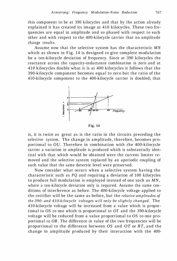
this component to be at 390 kilocycles and that by the action alreadyexplained it has created its image at 410 kilocycles. These two fre-quencies are equal in amplitude and so phased with respect to eachother and with respect to the 400-kilocycle carrier that no amplitudechange results.
Assume now that the selective system has the characteristic MNwhich as shown in Fig. 14 is designed to give complete modulationfor a ten-kilocycle deviation of frequency. Since at 390 kilocycles thereactance across the capacity-inductance combination is zero and at410 kilocycles double what it is at 400 kilocycles it follows that the390-kilocycle component becomes equal to zero but the ratio of the410-kilocycle component to the 400-kilocycle carrier is doubled; that
is, it is twice as great as is the ratio in the circuits preceding theselective system. The change in amplitude, therefore, becomes pro-
Fig. 14
portional to OU. Therefore in combination with the 400-kilocyclecarrier a variation in amplitude is produced which is substantially iden-tical with that which would be obtained were the current limiter re-moved and the selective system replaced by an aperiodic coupling ofsuch value that the same detector level were preserved.
Now consider what occurs when a selective system having thecharacteristic such as PQ and requiring a deviation of 100 kilocyclesto produce full modulation is employed instead of one such as MN,where a ten-kilocycle deviation only is required. Assume the same con-ditions of interference as before. The 400-kilocycle voltage applied tothe rectifier will be the same as before, but the relative amplitudes ofthe 390- and 410-kilocycle voltages will only be slightly changed. The410-kilocycle voltage will be increased from a value which is propor-tional to OS to one which is proportional to OT and the 390-kilocyclevoltage will be reduced from a value proportional to OS to one pro-portional to OR. The difference in value of the two frequencies will beproportional to the difference between OS and OT or RT, and thechange in amplitude produced by their interaction with the 400-

708 Armstrong: Frequency Modulation-Noise Reduction
kilocycle current will be likewise proportional to RT. The reduction inthe amplitude of the disturbance as measured in the detector outputby the use of a 200-kilocycle wide selective system as compared to theuse of one only twenty kilocycles wide is therefore the ratio RT/OU.In this case it is ten per cent. The power ratio is the square of this orone per cent.
The above reasoning holds equally well if a balanced rectifyingsystem is used where the characteristics of the selective system are asshown in Fig. 15. The output of the system insofar as voltages result-ing from changes in frequency are concerned is the sum of outputs ofthe two sides of the balance.
Fig. 15 Fig. 16
It is of course clear that disturbing currents lying farther from the400-kilocycle point than the ten-kilocycle limit will, by interaction withthe 400-kilocycle current, produce larger values of rectified currentthan those lying within that band, But the rectified currents produced inthe detector output by those components of frequency which lie at a greaterthan audible frequency distance from the 400-kilocycle current will bebeyond the audible range and hence will produce no disturbance whichis audible. (It is generally advisable to eliminate them from the audioamplifier by a low-pass filter to prevent some incidental rectificationin the amplifier making their variations in amplitude audible.)
It remains only to consider what happens when the frequency ofthe 400-kilocycle current is varied in accordance with modulation atthe transmitter. It is clear from Fig. 14 that when the selective systemhas the characteristic MN that a deviation of 10,000 cycles will pro-duce complete modulation of the signal or a change in amplitude pro-portional to OU. Similarly, when the characteristic is according tothe curve PQ it is clear that a l00,000-cycle deviation is required toproduce complete modulation, which is likewise proportional to the samevalue OU. As the signal current is swung back and forth over therange of frequencies between 300 and 500 kilocycles the band of fre-

Armstrong: Frequency Modulation-Noise Reduction 709
quencies from which the audible interference is derived continuallychanges, the band progressively lying about ten kilocycles above andten kilocycles below what we may call the instantaneous value of thefrequency of the signal. The effect is illustrated by Fig. 16 and fromthis it will be seen that the amplitude of the disturbances in the outputcircuit of the rectifiers, which is proportional to the sum of RT andRT will be constant. This will be true where the ratio of the amplitudeof the signal to the disturbing currents is sufficiently large-wherethis condition does not exist then there are certain other effects whichmodify the results, but these effects will only be of importance at thelimits of the practical working range.
COMPARISON OF NOISE RATIOS OF AMPLITUDE AND FREQUENCY
MODULATION SYSTEMS
From the foregoing description it will be clear that as between twofrequency modulation systems of different band widths the signal-to-noise power ratio in the rectified output will vary directly as the squareof the band width (provided the noise voltage at the current limiter isless than the signaling voltage). Thus doubling the band width pro-duces an improvement of 4 to 1 and increasing it tenfold an improve-ment of 100 to 1.
The comparison of relative noise ratios of amplitude and frequencymodulation systems cannot be made on so simple a basis as there area number of new factors which enter, particularly when the compari-son is viewed from the very practical aspect of how much greaterpower must be used with an amplitude modulated transmitter thanwith a frequency modulated one. If the academic comparison be madebetween a frequency modulated system having a deviation of ten kilo-cycles and an amplitude modulated one of similar band width and thesame carrier level (also same fidelity), it will be found that the signal-to-noise voltage ratio as measured by a root-mean-square meter willfavor the frequency modulation system by about 1.7 to 1, and thatthe corresponding power ratio will be about 3 to 1. This improvementis due to the fact that in the frequency modulation receiver it-is onlythose noise components which lie at the extremes of the band; viz.,ten kilocycles away from the carrier which, by interaction with thecarrier (when unmodulated) can produce the same amplitude of‘recti-fied current as will be produced by the corresponding noise componentin the amplitude modulated receiver.
Those components which lie closer to the carrier than ten kilocycleswill produce a smaller rectified voltage, the value of this depending ontheir relative distance from the carrier. Hence the distribution of en-

710 Armstrong: Frequency Modulation-Noise Reduction
ergy in the rectified current will not be uniform with respect to fre-quency but will increase from zero at zero frequency up to a maximumat the limit of the width of the receiver, which is ten kilocycles in thepresent case. The root-mean-square value of the voltage under such adistribution is approximately 0.6 of the value produced with the uni-form distribution of the amplitude receiver.
Similarly in comparing an amplitude modulation system arrangedto receive ten-kilocycle modulations and having, of course, a bandwidth of twenty kilocycles, with a l00-kilocycle deviation frequency
Fig. 17
modulation system (same carrier level and same fidelity) there will bean improvement in noise voltage ratio of
deviation1.7 x
100or 1.7 X --- = 17.
audio-frequency range 10
The above comparisons have been made on the basis of equal car-rier. The practical basis of comparison between the two is that ofhalf carrier for the amplitude modulation and full carrier for the fre-quency modulation system. This results in about the equivalentamount of power being drawn from the mains by the two systems. Onthis basis the voltage improvement becomes thirty-four and the signal-to-noise power ratio 1156. Where the signal level is sufficiently largewith respect to the noise it has been found possible to realize improve-ments of this order.
The relative output signal-to-noise ratios of an amplitude modula-tion system fifteen kilocycles wide (7.5-kilocycle modulation frequency)and a frequency modulation system 150 kilocycles wide (75-kilocycledeviation) operating on forty-one megacycles have been compared onthe basis of equal fidelity and half carrier for amplitude modulation,

Armstrong: Frequency Modulation-Noise Reduction 711
The characteristic of the selective system for converting frequencychanges to amplitude changes, which was used, is shown in Fig. 17.The variation of the output signal-to-noise ratio with respect to thecorresponding radio-frequency voltage ratio is illustrated in Fig. 18.The curves show that where the radio-frequency peak voltage of thenoise measured at the current limiter is less than ten per cent of the
Fig. 18
signal peak voltage then the energy of the disturbance in the rectifiedoutput will be reduced by a factor which is approximately 1100 to 1.When the peak radio-frequency noise voltage is twenty-five per centof the signal peak voltage then the energy of the disturbance in therectified output has been reduced to about 700 to 1, and when it isfifty per cent the reduction of the disturbance drops below 500 to 1.Finally when the noise and signal peak voltages become substantiallyequal the improvement drops to some very low value. While it is un-fortunate, of course, that the nature of the effect is such that theamount of noise reduction becomes less as the noise level rises withrespect to the signal, nevertheless this failing is not nearly so important


712 Armstrong: Frequency Modulation-Noise Reduction
as it would appear. In the field of high fidelity broadcasting a signal-to-noise voltage ratio of at least 100 to 1 is required for satisfactory re-ception. It is just within those ranges of noise ratios which can bereduced to this low level that the system is most effective.
The arrangements employed in obtaining these characteristics andthe precautions which must be observed may perhaps be of interest.As it was obviously impracticable to vary the power of a transmitterover the ranges required or to eliminate the fading factor except overshort periods of time an expedient was adopted. This expedient con-sisted in tuning the receiver to the carrier of a distant station, deter-mining levels and then substituting for the distant station a local signalgenerator, the distant station remaining shut down except as it was
4OOK.C. AmplifierASK.C Band Rectifier
OsMutor 05ci/lator
400 K.C AmplifierI50 K.C. Band
StandardSigna/Generator
Filter Rectifier
Voftuqe
Ampf&fier Speuker
Fig. 19
called upon to check specific points on the curve. Observations weretaken only when the noise was due solely to thermal agitation and shoteffect.
Fig. 19 shows the arrangement of apparatus. The receiver was atwo-intermediate-frequency superheterodyne with provision for usingeither a narrow band second intermediate amplifier with the amplitudemodulation system or a wide band amplifier with the frequency modu-lation system. The band width of the amplitude modulation systemwas fifteen kilocycles or twice the modulation frequency range. Theband width of the frequency modulation receiver was 150 kilocycles ortwice the frequency deviation. Provision was made for shifting fromone intermediate amplifier to the other without disturbing the re-mainder of the system, The forty-one-megacycle circuits and the firstintermediate amplifier circuits were wide enough to pass the frequencyswing of 150 kilocycles. Identical detection systems were used, the fre-quency modulation detector being preceded by a selective system for

Armstrong: Frequency Modulation-Noise Reduction 713
translating changes in frequency into changes in amplitude. The outputcircuits of the detectors were arranged to be connected alternately toa 7500-cycle low-pass filter with a voltage divider across its output. Anamplifier with a flat characteristic over the audible range and aroot-mean-square meter connected through a high-pass, 500-cycle filterprovided the visual indication.
The standard signal was introduced into the input of the twobranches of the second intermediate-frequency stage at 400 kilocycles.As long as the receiver is linear between the antenna and the point atwhich the standard signal is introduced it is immaterial whether thesignal be of forty-one megacycles, six megacycles, or 400 kilocycles.This has been checked experimentally but 400 kilocycles was chosen onaccount of the greater accuracy of the signal generator on low frequen-cies.
The relative noise levels to be compared varied over such rangesthat lack of linearity had to be guarded against and readings were madeby bringing the output meter to the same point on the scale each timeby adjustment of the voltage divider, and obtaining the relative volt-ages directly from the divider.
Two other precautions are essential. The absolute value of thenoise voltage on the frequency modulation system becomes very lowfor high signal levels. If the voltages due to thermal agitation andshot effect are to be measured rather than those due to the power sup-ply system the output meter must be protected by a high-pass filter ofhigh attentuation for the frequencies produced by the power system.The cutoff point should be kept as low as possible since because of thedifference in the distribution of energy in the rectified outputs of fre-quency and amplitude modulation receivers already referred to thereis a certain error introduced by this filter which is small if the bandwidth excluded by the filter is small but which can become appreciableif too much of the low-frequency part of the modulation frequencyrange be suppressed.
A second precaution is the use of a low-pass filter to cut off fre-quencies above the modulation range. Because of the wide band passedby the amplifiers of the frequency modulation part of the system thereexists in the detector output rectified currents of frequencies up toseventy-five kilocycles. The amplitude of these higher frequencies ismuch greater than those lying within the audible range. The averagedetector output transformer will readily pass a substantial part of thesesuperaudible frequencies which then register their effect upon the out-put meter although they in no way contribute to the audible dis-turbance.

714 Armstrong: Frequency Modulation-Noise Reduction
The procedure which was followed in making the measurementswe are considering consisted in tuning the receiver to the distant trans-mitter and adjusting the two detector levels to the same value for therespective carrier levels to be employed. This was done by cuttingthe carrier in half at the transmitter when the amplitude modulationdetector level was being set and using full carrier for the adjustmentof the frequency modulation detector. Each system was then modu-lated seventy-five per cent and output voltages checked against eachother. If they were equal the modulation was removed and the relativenoise voltages measured for the respective carrier levels. This gave thefirst point on the curve. The transmitter was then shut down anda local carrier introduced which gave the same level in the 400-kilocycleintermediate amplifier circuits as the half carrier distant signal. Thislevel was directly ascertainable from the rectified detector current inthe amplitude modulation system. From this point on the procedurewas entirely within the control of the receiving station. The noiseratios could be compared at any signal level by adjusting the voltageintroduced by the signal generator to any fraction of that of the distantsignal, bringing the level in the amplitude modulation detector up tothe same original va lue by adjustment of the amplification of thesecond intermediate amplifier (the frequency modulation detector staysat its point of reference because of the current limiter) and comparingthe two output voltages. The level of the detector in the amplitudemodulation receiver was of course set with the half carrier value of thesignal generator and the output voltage measured at that level. Theoutput voltage of the frequency modulation system was measuredwhen twice that voltage was applied.
It is important to keep in mind just what quantities have been meas-ured and what the curves show. The results are a comparison betweenthe relative noise levels in the two systems (root-mean-square values)when they are unmodulated. In both an amplitude and in a frequencymodulation receiver the noise during modulation may be greater thanthat obtained without modulation. In the frequency modulation re-ceiver two principal sources may contribute to this increase, one ofwhich is of importance only where the band for which the receiver isdesigned is narrow, the other of which is common to all band widths.If the total band width of the receiver is twenty kilocycles and if thedeviation is, for example, ten kilocycles, then as the carrier frequencyswings off to one side of the band, it approaches close to the limit ofthe filtering system of the receiver. Since the sides of the filter arenormally much steeper than the selective system employed to convertthe changes in frequency into amplitude variations and since the fre-

Armstrong: Frequency Modulation-Noise Reduction 715
quency of the signaling current will have approached to within therange of good audibility of the side of the filter a considerable increasein both audibility and amplitude of the disturbance may occur, causedby the sides of the filter acting as the translating device. This effect isobviously not of importance where a wider frequency swing is em-ployed.
The other source of noise which may occur when the signal fre-quency swings over the full range is found in systems of all bandwidths. It was first observed on an unmodulated signal when it wasnoted that swinging the intermediate frequency from the mid-point toone side or the other by adjustment of the frequency of the first hetero-dyne produced an increase in the amplitude and a change in the charac-ter of the noise. The-effect was noted on a balanced detector system andat first it was attributed to the destruction of the amplitude balanceas one detector current became greater than the other. Subsequentlywhen it was noted that the increase in the noise was produced by thedetector with the smaller current and that the effect was most pro-nounced when the signal level was relatively low, the explanationbecame apparent. As long as the signal frequency was set at the mid-point of the band its level in the detector was sufficiently large toprevent the production of audible beats between the noise componentslying respectively at the two ends of the band where the reactance ofthe selective systems is a maximum.
When however the signal frequency moves over to one side of theband the amplitude of the voltage applied to one of the detectors pro-gressively decreases, approaching zero as the frequency coincides withthe zero reactance point of the selective system. The demodulatingeffect of the signaling current therefore disappears and the noise com-ponents throughout the band, particularly those at the other side of it,are therefore free to beat with each other. The noise produced is thecharacteristic one obtained when the high-frequency currents causedby thermal agitation and shot effect are rectified in a detector withoutpresence of a carrier. The effect is not of any great importance on theordinary working levels for simplex operation, although it may becomeso in multiplex operation. It indicates, however, that where the signal-to-noise level is low, complete modulation of the received signal by theconversion system is not desirable and that an adjustment of the de-gree of modulation for various relative noise levels is advantageous.
In the course of a long series of comparisons between the twosystems a physiological effect of considerable importance was noted. Itwas observed that while a root-mean-square meter might show thesame reading for two sources of noise, one derived from an amplitude

716 Armstrong: Frequency Modulation-Noise Reduction
modulation, and the other from a frequency modulation receiver (bothof the same fidelity) that the disturbance perceived by the ear was moreannoying on the amplitude modulation system. The reason for this isthe difference in the distribution of the noise voltage with respect tofrequency in the rectified output currents of the two systems, the dis-tribution being substantially uniform in the amplitude system butproportional to frequency in the frequency modulation system. Hencein the latter there is a marked absence of those frequencies which liein the range to which the ear is the most sensitive. With most observersthis difference results in their appraising a disturbance produced inthe speaker by an amplitude modulation system as the equivalent’ofone produced therein by a frequency modulation system of about 1.5times the root-mean-square voltage although of course the factor variesconsiderably with the frequency range under consideration and thecharacteristic of the individual’s aural system.
On account of this difference in distribution of energy the correctmethod of procedure in making the comparison is that given in thearticle by Ballantine, l6 but lack of facilities for such determinationsmade necessary the use of a root-mean-square meter for the simul-taneous measurement of the entire noise frequency range. The increasein noise voltage per frequency interval with the frequency may bereadily demonstrated by means of the ordinary harmonic analyzer ofthe type now so generally used for the measurement of distortion.Because of the extremely narrow frequency interval of these instru-ments it is not possible to obtain sufficient integration to produce stablemeter readings and apparatus having a wider frequency interval thanthe crystal filter type of analyzer must be used. The observation of theaction of one of these analyzers will furnish convincing proof that peakvoltmeter methods must not be used in comparing the rectified outputcurrents in frequency and amplitude modulation receivers.
All the measurements which have been heretofore discussed weretaken under conditions in which the disturbing currents had theirorigin in either thermal agitation or shot effect, as the irregularity ofatmospheric disturbances or those due to automobile ignition systemswere too irregular to permit reproducible results. The curves applygenerally to other types of disturbances provided the disturbing voltageis not greater than that of the signal. When that occurs a differentsituation exists and will be considered in detail later.
There are numerous second order effects produced, but as theyare of no great importance consideration of them will not be under-taken in the present paper.

Armstrong: Frequency Modulation-Noise Reduction 717
THE NEW YORK-WESTHAMPTON AND HADDONFIELD TESTS
The years of research required before field tests could even beconsidered were carried out in the Marcellus Hartley Research Labora-tory at Columbia University. Of necessity both ends of the circuit hadto be under observation simultaneously and a locally generated signalwas used: The source of signal ultimately employed consisted of astandard signal generator based upon the principle of modulation al-ready described and capable of giving 150,000 cycles swing on forty-four megacycles. The generator was also arranged to give amplitudemodulated signals. Suitable switching arrangements for changingrapidly from frequency to amplitude modulation at either full or halfcarrier were set up and a characteristic similar to that of Fig. 18 ulti-mately obtained.
A complete receiving system was constructed and during theWinter of 1933-1934 a series of demonstrations were made to theexecutives and engineers of the Radio Corporation of America. Thatwholly justifiable suspicion with which all laboratory demonstrationsof “static eliminators” should be properly regarded was relieved whenC. W. Horn of the National Broadcasting Company placed at thewriter’s disposal a transmitter in that company’s experimental stationlocated on top of the Empire State Building in New York City. Thetransmitter used for the sight channel of the television system de-livered about two kilowatts of power at forty-four megacycles to theantenna and it was the one selected for use. This offer of Mr. Horn’sgreatly facilitated the practical application of the system as it elimi-nated the necessity of transmitter construction in a difficult field andfurnished the highly skilled assistance of R. E. Shelby and T. J.Buzalski, the active staff of the station at that time. Numerous diffi-culties, real and imaginary, required much careful measurement toascertain their presence or absence and the relative importance ofthose actually existing. The most troublesome was due to the positionof the transmitter, which is located on the eighty-fifth floor of the build-ing and is connected by a concentric transmission line approximately275 feet long with a vertical dipole antenna about 1250 feet aboveground. Investigation of the characteristics of this link between trans-mitter and antenna showed it to be so poorly matched to the antennathat the resulting standing waves attained very large amplitude. Theproblem of termination afforded peculiar -difficulties because of thesevere structural requirements of the antenna above the roof and ofthe transmission line below it. It was however completely solved byP. S. Carter of the R.C.A. Communications Company in a very

718 Armstrong: Frequency Modulation-Noise Reduction
beautiful manner, the standing waves being practically eliminatedand the antenna broadened beyond all requirements of the modulatingsystem contemplated. With the transmitter circuits no difficulty wasencountered at this time. The frequency of the system was ordinarilycontrolled by a master oscillator operating at 1733 kilocycles whichwas multiplied by a series of doublers and a tripler to forty-four mega-cycles. The multiplier and amplifier circuits were found to be suffi-ciently broad for the purposes of the initial tests.
The crystal control oscillator was replaced by the output of themodulation system shown in Fig. 20 in which an initial frequency of57.33 kilocycles was multiplied by a series of doublers up to the inputfrequency of the transmitter of 1733 kilocycles. It was found possibleto operate this apparatus as it is shown installed in the shielded room
Fig. 20
of the television studio at the Empire State station as the shieldingfurnished ample protection against the effects of the high power stagesof the transmitter located some seventy-five feet away.
The receiving site selected was at the home of George E. Burghardat Westhampton Beach, Long Island, one of the original pioneers ofamateur radio, where a modern amateur station with all facilities, in-cluding those for rigging directive antennas, were at hand. Westhamp-ton is about sixty-five miles from New York and 800 or 900 feet belowline of sight.
The installation is illustrated in Figs. 21 and 22 which show bothfrequency and amplitude modulation receivers and some of the meas-uring equipment for comparing them. The frequency modulation re-ceiver consisted of three stages of radio-frequency amplification (atforty-one megacycles) giving a gain in voltage of about 100. This fre-quency was heterodyned down to six megacycles where an amplifica-tion of about 2000 was available and this frequency was in turn hetero-

Armstrong: Frequency Modulation-Noise Reduction 719
dyned down to 400 kilocycles where an amplification of about 1000could be realized. Two current limiting systems in cascade each with aseparate amplifier were used. At the time the photograph was takenthe first two radio-frequency stages had been discarded.
Fig. 21
The initial tests in the early part of June surpassed all expectations.Reception was perfect on any of the antennas employed, a ten-foot wirefurnishing sufficient pickup to eliminate all background noises. Suc-
Fig. 22
cessive reductions of power at the transmitter culminated at a levelsubsequently determined as approximately twenty watts. This gave asignal comparable to that received from the regular New York broad-cast stations (except WEAF, a fifty-kilowatt station- approximatelyforty miles away).

720 Armstrong: Frequency Modulation-Noise Reduction
The margin of superiority of the frequency modulation system overamplitude modulation at forty-one megacycles was so great that it wasat once obvious that comparisons of the two were principally of aca-demic interest.
The real question of great engineering and economic importancewas the comparison of the ultra-short-wave’ frequency modulationsystem with the existing broadcast service and the determination ofthe question of whether the service area of the existing stations couldnot be more effectively covered than at present. The remainder of themonth was devoted to such a comparison. With the Empire Statetransmitter operating with approximately two kilowatts in the an-tenna, at all times and under all conditions the service was superior tothat provided by the existing fifty-kilowatt stations, this including sta-tion WEAF. During thunderstorms, unless lightning was strikingwithin a few miles of Westhampton, no disturbance at all would appearon the system, while all programs on the regular broadcast systemwould be in a hopeless condition. Background noise due to thermal agi-tation and tube hiss were likewise much less than on the regular broad-cast system.
The work at Westhampton demonstrated that in comparing thismethod of transmission with existing methods two classes of servicesand two bases of comparisons must be used. It was found that the onlytype of disturbarice of the slightest importance was that caused by theignition systems of automobiles, where the peak voltage developed bythe interferenqe was greater than the carrier level. In point-to-pointcommunication this difficulty can be readily guarded against by properlocation of the receiving system, and then thermal agitation and shoteffect are the principal sources of disturbance; lightning, unless in theimmediate vicinity, rarely producing voltages in excess of the carrierlevel which would normally be employed to suppress the thermal andshot effects. Under these conditions the full effect of noise suppressionis realized and comparisons can be made with precision by means ofthe method already described in this paper. An illustration of thepractical accomplishment of this occurred at Arney’s Mount, the tele-vision relay point between New York and Camden of the Radio Cor-poration of America. This station is located about sixty miles from theEmpire State Building and the top of the tower is only a few feetbelow line of sight. It is in an isolated spot and the noise level is al-most entirely that due to the thermal and shot effects. It was noted byC. M. Burrill of the RCA Manufacturing Company who made theobservations at Arney’s Mount that with fifty watts in the antennafrequency modulated (produced by a pair of UX 852 tubes), a signal-

Armstrong: Frequency Modulation-Noise Reduction 721
to-noise ratio of the same value as the two-kilowatt amplitude modula-tion transmitter (eight-kilowatt peaks) was obtained.
The power amplifier and the intermediate power amplifier of thefrequency modulation transmitter is shown in Fig. 23. The signal withfifty watts output would undoubtedly have had a better noise ratiothan the two-kilowatt amplitude modulation system had full deviationof seventy-five kilocycles been employed, but on the occasion it wasnot possible to use a deviation of greater than twenty-five kilocycles.It was also observed at the same time that when the plate voltage onthe power amplifier was raised to give a power of the order of 200watts in the antenna a better signal-to-noise ratio was obtained than
Fig. 23
that which could be produced by the two-kilowatt amplitude modula-tion. A casual comparison of the power amplifier stages of the frequencymodulation transmitter shown in Fig. 23 with the water-cooled poweramplifier and modulation stages of the Empire State transmitter ismore eloquent than any curves which may be shown herein.
In the broadcast service no such choice of location is possible and awidely variable set of conditions must be met. Depending on the powerat the transmitter, the elevation of the antenna, the contour of theintervening country, and the intensity of the interference there will bea certain distance at which peaks of ignition noise become greater thanthe carrier. The irregularity and difficulty of reproduction of these dis-turbances require a different method of comparison which will be here-inafter described.
As the site at Westhampton, which was on a section of the beachremote from man-made static, was obviously too favorable a site, anew one was selected in Haddonfield, New Jersey, and about the end ofJune the receiving apparatus was moved there and erected at the home

722 Armstrong: Frequency Modulation-Noise Reduction
of Harry Sadenwater. Haddonfield is located about eighty-five milesfrom New York in the vicinity of Camden, New Jersey, and. is over1000 feet below line of sight of the top of the Empire State Building inNew York. Although the field strength at Haddonfield was consider-ably below that at Westhampton Beach, good reception was obtainedalmost immediately, the sole source of noise heard being ignition noise
Fig. 24
from a few types of cars in the immediate vicinity of the antenna, orlightning striking within a few miles of the station. At this distancefading made its appearance for the first time, a rapid flutter varyingin amplitude three- or four-to-one being frequently observable on themeters. The effect of it was not that of the selective fading so wellknown in present-day broadcasting. Very violent variations as indi-cated by the .meters occurred without a trace of distortion being heard

Armstrong: Frequency Modulation-Noise Reduction 723
in the speaker. During a period of over a year in which observa-tions have been made at Haddonfield, but two short periods of fadinghave been observed where the signal sank to a level sufficient to bringin objectionable noise, one of these occurring prior to an insulationfailure at the transmitter.
It is a curious fact that the distant fading, pronounced though itmay be at times, is not so violent as that which may be encountered ata receiving station located within the city limits of New York. Theeffect, which appears to be caused by moving objects in the vicinity ofthe receiving antenna, causes fluctuations of great violence. In was ap-
Fig. 25
parently first observed by L. F. Jones of the RCA ManufacturingCompany within a distance of half a mile of the Empire State trans-mitter. It occurs continually at Columbia University located aboutfour miles from the Empire State transmitter but no injurious effecton the quality of transmission has ever been noted.
While at first, because of the lower field strength at Haddonfieldand the greater prevalence of ignition disturbances, the superiorityover the regular broadcast service was not so marked as at Westhamp-ton Beach, the subsequent improvements which were instituted atboth transmitting and receiving ends of the circuit have more thanoffset the lower signal level. Some idea of their extent may be gained bycomparison of the initial and final antenna structures. Fig. 24 showsthe original antenna during course of erection, a sixty-five foot mastbearing in the direction of New York permitting the use of an eight-wave length sloping wire of very useful directive properties. Fig. 25

724 Armstrong: Frequency Modulation-Noise Reduction
shows the final form on which the results are now much better thanwere originally obtained with the directional wire.
During the past summer, which was marked by thunderstorms ofgreat severity in the vicinity of Philadelphia, it was the exception whenit was agreeable or even possible to listen to the nightly programs ofthe regular broadcast service from the fifty-kilowatt NewYork stations.In some of the heaviest storms when lightning was striking within theimmediate vicinity of the antenna, so close in fact that the lead-in wassparking to a near-by water pipe, perfectly understandable speechcould be received on the frequency modulation system, although thedisturbance was sufficient to cause annoyance on a musical program;but these periods seldom lasted more than fifteen minutes when thecircuit would again become quiet. On numerous occasions the EmpireState signal was better than that of the fifty-kilowatt Philadelphia sta-tion WCAU located at a distance of twenty miles from Haddonfield.Likewise during periods of severe selective side-band fading in thebroadcast band which occurs even from station WJZ at Bound Brook,New Jersey, some sixty miles away, no signs of this difficulty wouldappear on the ultra-high-frequency wave.
Some of the changes which contributed to the improvement duringthe past year may be of interest. The introduction of the Thompson-Rose tube permitted the radio-frequency amplification required atforty-one megacycles to be accomplished with one stage and with con-siderable improvement of signal-to-noise ratio. It had a further inter-esting result. The tubes previously used for amplifying at this fre-quency were those developed by the Radio Corporation for the ultra-short-wave interisland communication system in the Hawaiian Islands.On account of the relatively low amplification factor of these tubes theshot effect in the plate circuit of the first tube exceeded the disturbancesdue to thermal agitation in the input circuit of that tube by a consider-able amount. With the acorn type tube, however, the situation is re-versed, the thermal noise contributing about seventy-five per cent ofthe rectified output voltage.
It should be noted here by those who may have occasion to makethis measurement on a frequency modulation system that it cannot bemade in the ordinary way by simply mis-tuning the input circuit to thefirst tube. To do so would remove the carrier from the current limiterand be followed by a roar of noise. The measurement must be madewith a local signal of the proper strength introduced into one of theintermediate-frequency amplifiers. Under these conditions the antennamay be mis-tuned without interfering with the normal action of thelimiter and the relative amounts of noise due to the two sources mayreadily be segregated.

Armstrong: Frequency Modulation-Noise Reduction 725
Considerable trouble was caused during the early stages of the ex-periments by an order of the Federal Radio Commission requiring thechanging of the frequency of the Empire State transmitter from forty-four to forty-one megacycles; this necessitating the realignment of thelarge number of interstage transformers in the modulating equipmentshown in Fig. 20 and also the retermination of the antenna. It, however,led to the application of the idea inherent in superheterodyne design.
Fig. 26
While the circuits of the old modulator were temporarily modified andwork carried on, a new modulation system was designed standardizingon an initial frequency of 100 kilocycles which was then multiplied by aseries of doublers up to 12,800 kilocycles. By means of a local oscillatorthis frequency was heterodyned down to 1708 kilocycles, the new valueof input frequency to the transmitter required to produce forty-onemegacycles in the antenna. Any future changes in wave length can bemade by merely changing the frequency of this second oscillator, Thefrequencies chosen were such that a deviation of 100 kilocycles couldbe obtained without difficulty, because of the extra number of fre-quency multiplications introduced. Fig. 26 shows the two modulationsystems during the process of reconstruction with arrangements formaking the necessary step-by-step comparisons between them.

726 Armstrong: Frequency Modulation-Noise Reduction
Much attention was paid during the year to the frequency char-acteristic of the transmitter, which was made substantially flat fromthirty to 20,000 cycles. This required careful attention to the charac-teristics of the doubler and amplifier circuits of the transmitter, andto John Evans of the RCA Manufacturing Company and to T. J.Buzalski I am indebted for its accomplishment. Continuous improve-ment of the transmitter and antenna efficiency was effected throughoutthe year, but of this phase of the development R. M. Morris of theNational Broadcasting Company, under whose direction the work wascarried on, is better qualified to speak. As the final step, the lines con-necting’the transmitter with the control board of the National Broad-casting Company at Radio City, from which the test programs wereusually supplied, were equalized to about 13,000 cycles, and when thishad been done the quality of reception at Haddonfield was far betterthan that obtainable from any of the regular broadcast stations.
INTERFERENCE AND FADING
Reference has heretofore been made to the difficulty of comparingthe amounts of interference produced in amplitude and frequencymodulation systems by the transient type of disturbance, particularlywhen, as in ignition noise, the peaks are greater in amplitude than thesignal carrier. The best method of comparison seems to be that ofobserving how much greater signal level from the standard signal gen-erator must be introduced into the receiving system when it is arrangedto receive amplitude modulation than is required for the same signal-to-noise ratio on a frequency modulated system. The experimentalprocedure of making such comparison is to change the connection ofthe speaker rapidly from one receiver to the other, simultaneouslychanging the level of the local generator until the two disturbances asperceived by the ear are equal. At all times, of course, the amplifica-tion in the amplitude modulation receiver is correspondingly changedas the signal generator level is varied to apply the same voltage to theamplitude as to the frequency modulation detector so that the audio-frequency signal level which will be produced by the two systems is thesame. The square of the ratio of the two voltages of the signal generatorgives the factor by which the carrier power of the amplitude modulatedtransmitter must be increased to give equal performance. While themeasurement is difficult to make, the following approximations maygive some idea of the magnitudes involved.
If the peak voltage off the ignition noise is twice the carrier levelof the frequency modulation system, about 150 to 200 times the powermust be used in the carrier of the amplitude modulation system to

Armstrong: Frequency Modulatibn-Noise Reduction 727
reduce the disturbance level to the same value. When the peak volt-age is five times as great, about 35 to 4 0 times the power in the am-plitude modulation carrier is sufficient to produce equality.17 Theseobservations have been checked aurally and by the oscilloscope. Theresults of measurements where the disturbances are due solely to thethermal and shot effects have been compared to those obtained withthe method previously described and are found to check with it. Thechief value of this method of measurement, however, lies in the abilityto predict with certainty the signal level required to suppress all igni-tion noise. An experimental determination made at Haddonfield showsthat a signal introduced from the local generator which produces at thecurrent limiter ten times the voltage of the Empire State signal is suffi-cient to suppress the disturbance caused by the worst offender amongthe various cars tested. These cars were located as closely as possible tothe doublet antenna shown in Fig. 25, the distance being about fortyfeet. The increase in field strength necessary to produce this result canbe readily obtained by an increase in the transmitter power to twentyor twenty-five kilowatts and the use of a horizontally directionalantenna array. An increase in the field strength of three or four to oneby means of an array is within the bounds of engineering design so thatthe practical solution of the problem of this type of interference iscertainly at hand up to distances of one hundred miles.
So also is the solution of the problem at its source. It has been de-termined experimentally that the introduction of 10,000 ohms (a valueof resistance which is not injurious to motor performance) into thespark plug and distributor leads of the car referred to eliminates theinterference with the Empire State signal.
Since active steps are now being taken by the manufacturers ofmotor cars to solve the more difficult general problem, the particularone of interference with sets located in the home will thus automaticallydisappear. The problem of eliminating the disturbance caused by anautomobile ignition system in a receiving set whose antenna is a mini-mum of fifty feet away from the car is obviously a much simpler onethan that of eliminating the interference in a receiver located in the caror in another car a few feet away.
During the course of the experimental work in the laboratory a verystriking phenomenon was observed in the interference characteristicsbetween frequency modulation systems operating within the same waveband. The immunity of a frequency modulation system from interfer-ence created by another frequency modulated transmission is of the
17 Linear detection was used in the amplitude modulation receiver but nolimiting was employed.

728 Armstrong: Frequency Modulation-Noise Reduction
same order of magnitude as the immunity with regard to tube noises.This property merits the most careful study in the setting up of abroadcast system at those wave lengths at which the question of inter-station interference is a major factor. It is well known that when thecarriers of two amplitude modulated transmitters are sufficiently closein frequency to produce an audible beat that the service range of eachof them is limited to that distance at which the field strength of thedistant station becomes approximately equal to one per cent of thefield strength of the local station. As a consequence of this, the servicearea of each station is very greatly restricted; in fact the service areaof the two combined is but a small percentage of the area which isrendered useless for that frequency due to the presence thereon of thetwo interfering stations. With the wide band frequency modulationsystem, however, interference between two transmissions does not ap-pear until the field strength of the interfering station rises to a levelin the vicinity of fifty per cent of the field strength of the local one. Thereason for this lies in the fact, that while the interfering signal in beat-ing with the current of the local station under such conditions may beproducing a fifty per cent change in the voltage applied to the currentlimiter, the system is substantially immune to such variations in am-plitude. The only way in which the interfering signal can make itspresence manifest is by cross modulation of the frequency of the localsignal. Since, under the conditions, this cross modulation produces lessthan a thirty-degree phase shift and since the characteristics of the wideband receiver are such that, at least within the range of good audibility,thousands of degrees of phase shift are necessary to produce full modu-lation, it is clear that a thirty-degree phase shift will not produce verymuch of a rectified output. For example, assuming two unmodulatedcarriers are being received, that their amplitudes have a ratio of twoto one, and that their frequencies differ by 1000 cycles, then for a sys-tem having a wide band (of the order of 150,000 cycles) the modula-tion produced by the interaction of the two carriers would be of theorder of one per cent of that produced by full modulation of thestronger carrier. This example, however, represents perhaps the worstpossible condition as during modulation of either station, with theproper type of conversion system, the aural effect of the disturbanceis greatly reduced. The whole problem of interference between unmod-ulated carriers may, however, be entirely avoided by separating themin frequency by an amount beyond the audible range. Hence it follows that with two wide band frequency modulated transmitters occupyingthe same frequency band that only the small area located midway be-tween the two wherein the field strength of one station is less than
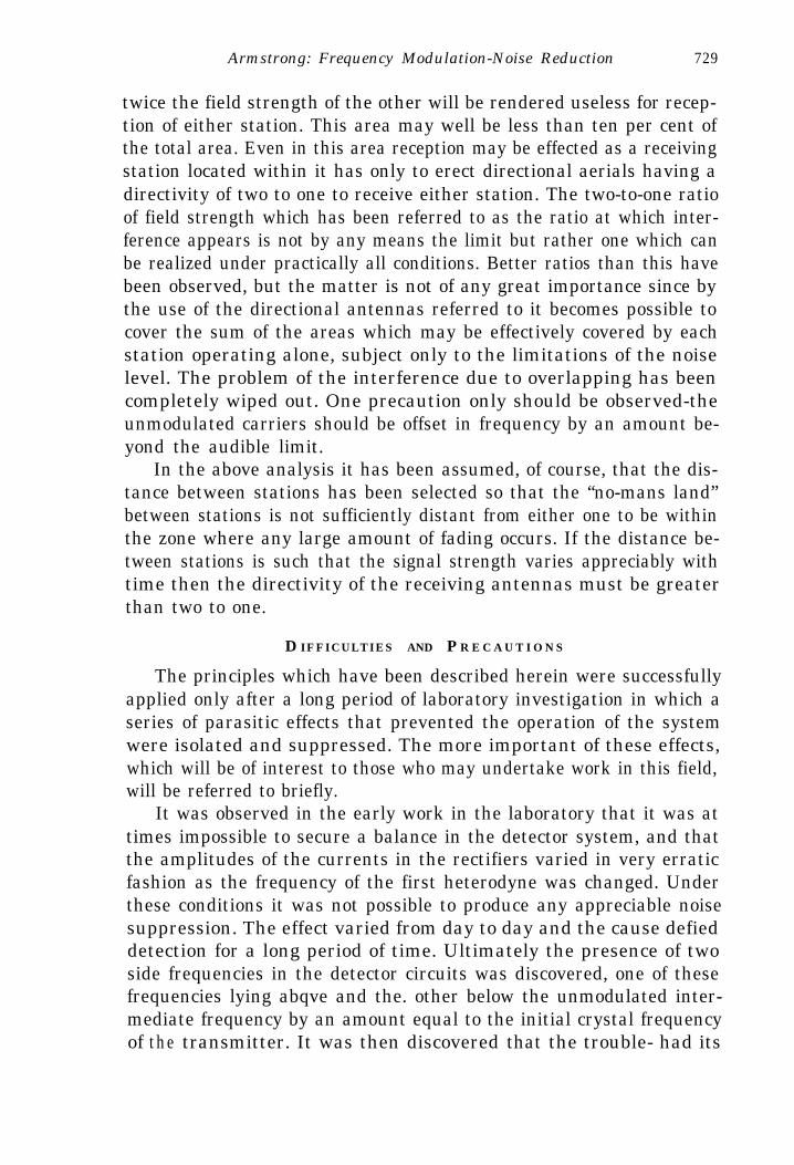
Armstrong: Frequency Modulation-Noise Reduction - 729
twice the field strength of the other will be rendered useless for recep-tion of either station. This area may well be less than ten per cent ofthe total area. Even in this area reception may be effected as a receivingstation located within it has only to erect directional aerials having adirectivity of two to one to receive either station. The two-to-one ratioof field strength which has been referred to as the ratio at which inter-ference appears is not by any means the limit but rather one which canbe realized under practically all conditions. Better ratios than this havebeen observed, but the matter is not of any great importance since bythe use of the directional antennas referred to it becomes possible tocover the sum of the areas which may be effectively covered by eachstation operating alone, subject only to the limitations of the noiselevel. The problem of the interference due to overlapping has beencompletely wiped out. One precaution only should be observed-theunmodulated carriers should be offset in frequency by an amount be-yond the audible limit.
In the above analysis it has been assumed, of course, that the dis-tance between stations has been selected so that the “no-mans land”between stations is not sufficiently distant from either one to be withinthe zone where any large amount of fading occurs. If the distance be-tween stations is such that the signal strength varies appreciably withtime then the directivity of the receiving antennas must be greaterthan two to one.
D IFFICULTIES AND P R E C A U T I O N S
The principles which have been described herein were successfullyapplied only after a long period of laboratory investigation in which aseries of parasitic effects that prevented the operation of the systemwere isolated and suppressed. The more important of these effects,which will be of interest to those who may undertake work in this field,will be referred to briefly.
It was observed in the early work in the laboratory that it was attimes impossible to secure a balance in the detector system, and thatthe amplitudes of the currents in the rectifiers varied in very erraticfashion as the frequency of the first heterodyne was changed. Underthese conditions it was not possible to produce any appreciable noisesuppression. The effect varied from day to day and the cause defieddetection for a long period of time. Ultimately the presence of twoside frequencies in the detector circuits was discovered, one of thesefrequencies lying abqve and the. other below the unmodulated inter-mediate frequency by an amount equal to the initial crystal frequencyof the transmitter. It was then discovered that the trouble- had its

730 Armstrong: Frequency Modulation--Noise Reduction
origin in the transmitting system and that a current having the funda-mental frequency of the crystal, (in the present case 57.33 kilocycles),passed through the first doubler circuits in such phase relation to thedoubled frequency as to modulate the doubled frequency at a rate cor-responding to 57.33 kilocycles per second. This modulation of fre-quency then passed through all the transmitter doubler stages, increas-ing in extent with each frequency multiplication and appearing finallyin the forty-four-megacycle output as a fifty-seven-kilocycle frequencymodulation of considerable magnitude. In the first doubler tank circuitof the transmitter a very slight change in the adjustment of the tuningof the circuit produced a very great change in the magnitude of thiseffect. A few degrees shift in the tuning of the first doubler tank con-denser, so small that an almost unnoticeable change in the plate currentof the doubler occurred, would increase the degree of the modulationto such extent as to make the first upper and lower side frequenciesinthe forty-four-megacycle current greater than the carrier or mid-fre-quency current (when no audio modulation was applied). Under suchconditions the proper functioning of the receiving system was impossi-ble.
The delay in uncovering this trouble lay in the fact that it was ob-scured by the direct effect of harmonics from the transmitter doublerstages which had to be set up in an adjoining room and by the numer-ous beats which can occur in a double intermediate-frequency super-heterodyne. To these effects were added an additional complicationcaused by the presence of harmonics in the circuits of the selectivesystem resulting from the action of the limiter which the filtering ar-rangements did not entirely remove. The coincidence of one of theseharmonics with the natural period of one of the inductances in thebranch circuits likewise interfered with the effectiveness of the noisesuppression. The causes of all these spurious effects were finally locatedand necessary steps, taken to eliminate them.
With the removal of these troubles a new one of a different kindcame to light, and for a time it appeared that there might be a veryserious fundamental limitation in the phase shifting method of generat-ing frequency modulation currents. There was found to be in the outputof the transmitter at forty-four megacycles a frequency modulationwhich produced a noise in the receiver similar to the usual tube hiss.The origin of it was traced to the input of the first doubler or the outputof the crystal oscillator where-a small deviation of the initial frequencywas produced by disturbances originating in these circuits. While thefrequency shift in this stage must have been very small, yet on accountof the great amount of frequency multiplication (of the order of 800I.

Armstrong: Frequency Modulation-Noise Reduction 731
times) it became extremely annoying in the receiver; in fact for lowlevels of receiver noise that noise which originated in the transmittedwave was by far the worse. For a time it seemed as though the amountof frequency multiplication which could be used in the transmitter waslimited by an inherent modulation of the frequency of the oscillatorby disturbances arising in the tube itself. The proper proportioning ofthe constants of the circuits, however, reduced this type of disturbanceto a point where it was no longer of importance and frequency multi-plications as high as 10,000 have since been effectively used. On ac-count of the very large amount of frequency multiplication, any troublesin these low-frequency circuits caused by noisy grid leaks, improper by-passing of power supply circuits, or reaction of one circuit upon anotherbecome very much more important than they would normally be. Diffi-culties of all these kinds were encountered, segregated, and eliminated.
Another source of trouble was discovered in the correction system.Because of the range in frequency required, particularly in multiplexwork where thirty to 30,000 cycles was frequently used, the outputvoltage of the correction system at the higher frequencies became verymuch less than the input voltage, hence any leakage or feed-forwardeffect due to coupling through the power supply circuits developed avoltage across the output much higher than that required by the in-verse frequency amplification factor as determined by the correctionnetwork. Hence, the frequency swing for the upper frequencies of modu-lation would frequently be several hundred per cent greater than itshould be. Likewise, at the lower frequency end of the scale variousreactions through the power supply were very troublesome. All theseeffects, however, were overcome and the correction system designed sothat its accuracy was within a few per cent of the proper value.
From, the foregoing it might be assumed that the transmitting andreceiving apparatus of this system are inherently subject to so manynew troubles and complications that their operation becomes imprac-ticable for ordinary commercial applications. Such is not the case. Thedifficulties are simply those of design, not of operation. Once the properprecautions are taken in the original design these difficulties neveroccur, except as occasioned by mechanical or electrical failure of mate-rial. During the period of over a year in which the Empire State trans-mitter was operated, only two failures chargeable to the modulatingsystem occurred. Both were caused by broken connections. Even thedesign problems are not serious as methods are now available for detect-ing the presence of any one of the troubles which have been here enu-merated.
These troubles were serious only when unsegregated and en masse

732 Armstrong: Frequency Modulation-Noise Reduction
they masked the true effects and made one wonder whether even thelaws of electrical phenomena had not been temporarily suspended.
M U L T I P L E X O P E R A T I O N
During the past year, two systems of multiplexing have been oper-ated successfully between New York and Haddenfield and it has been
Fig. 27
Fig. 28
found possible to transmit simultaneously the red and blue networkprograms of the National Broadcasting Company, or to transmit simul-taneously on the two channels the same program. This last is muchthe simpler thing to accomplish as the cross-talk problem is not a seri-ous one. The importance of multiplexing in point-to-point communi-cation services has long been recognized. In broadcasting there areseveral applications which, while their practical application may be
_long deferred, are clearly within view.


Armstrong: Frequency Modulation-Noise Reduction 733
Two general types of multiplexing were used. In one type a currentof superaudible frequency is caused to modulate the frequency of thetransmitted wave. The frequency at which the transmitted wave iscaused to deviate is the frequency of this current and the extent of thedeviation is varied in accordance with modulation of the amplitude ofthe superaudible frequency current. At the receiver detection is accom-
Mask?r LJ~f&?tOtor
FMse fiefuqqyShper Mu/ p/ief PA.
Fig. 29
plished by separating the superaudible current and its component mod-ulations from the rectified audible frequency currents of the main chan-nel and reproducing the original modulating current from them by asecond rectification. The general outline of the system is illustrated inFigs. 27 and 28. The setting of the levels of the main and auxiliarychannels must be made in this system of modulation with due regard
8.RFilfer
Detector Amp/ifier @eaker
Fig. 30
to the fact that the deviation of the transmitted wave produced by thesuperaudible frequency current of the second channel is a variable oneand changes between the limits of zero and double the unmodulateddeviation.
In the second method of multiplexing a superaudible current pro-duces a frequency modulation of the transmitted wave of constant devi-ation, the rate of the deviation being varied in accordance with thefrequency of the superaudible current and modulation being produced

734 Armstrong: Frequency Modulation-Noise Reduction
by varying the frequency of this auxiliary current and thereby the rateat which the superimposed modulation of frequency of the transmittedwave changes. The operations which must be carried out at the receiverare the following: After suitable amplification, limiting, and filtering,an initial conversion and rectification produces in the output of thedetector the audible frequencies of the main channel and a super-audible constant amplitude variable frequency current. This last isselected by means of a band-pass filter, passed through a second con-
Fig. 31
version system to translate the changes in the frequency into varia-tions of amplitude, and then rectified to recreate the initial modulatingcurrent of the auxiliary channel. The general arrangment of the sys-tem is illustrated in Figs. 29 and 30. This latter method of multiplex-ing has obvious advantages in the reduction of cross modulationbetween the channels and in the fact that the deviation of the trans-mitted wave produced by the second channel is constant. in extent, anadvantage being gamed thereby which is somewhat. akin to that ob-tained by frequency, as compared to amplitude, modulation in simplexoperation. The subject of the behavior of these systems with respect tointerference of various sorts is quite involved and will be reserved forfuture treatment as it is beyond the scope of the present paper.

Armstrong: Frequency Modulation-Noise Reduction 735
The final arrangement of the modulating equipment installed atthe Empire State station is illustrated in Figs. 31 and 32. The mainchannel apparatus is shown on the five tables located on the right sideof the room. The vertical rack in the left center contains three channelsfor transmitting facsimile by means of the amplitude modulationmethod of multiplexing already described. In Fig. 32, located on thefour tables on the left of the room is shown the auxiliary channel ofthe frequency modulation type already described. The comparatively
Fig. 32
low frequency of this channel was obtained by the regular method ofphase shifting and frequency multiplication, the frequency multiplica-tion being carried to a high order and the resultant frequency modu-lated current, heterodyned down to twenty-five kilocycles (mid-fre-quency). A deviation up to ten ‘kilocycles was obtainable at thisfrequency.
The receiving apparatus located at Haddonfield is illustrated inFigs. 33 and 34. Fig. 33 shows the modified Westhampton receiverand Fig. 34 the multiplex channels of the receiver. The vertical rack tothe right holds a three-channel receiver of the amplitude modulationtype. The two panels in the foreground constitute the frequency modu-lation type of auxiliary channel.
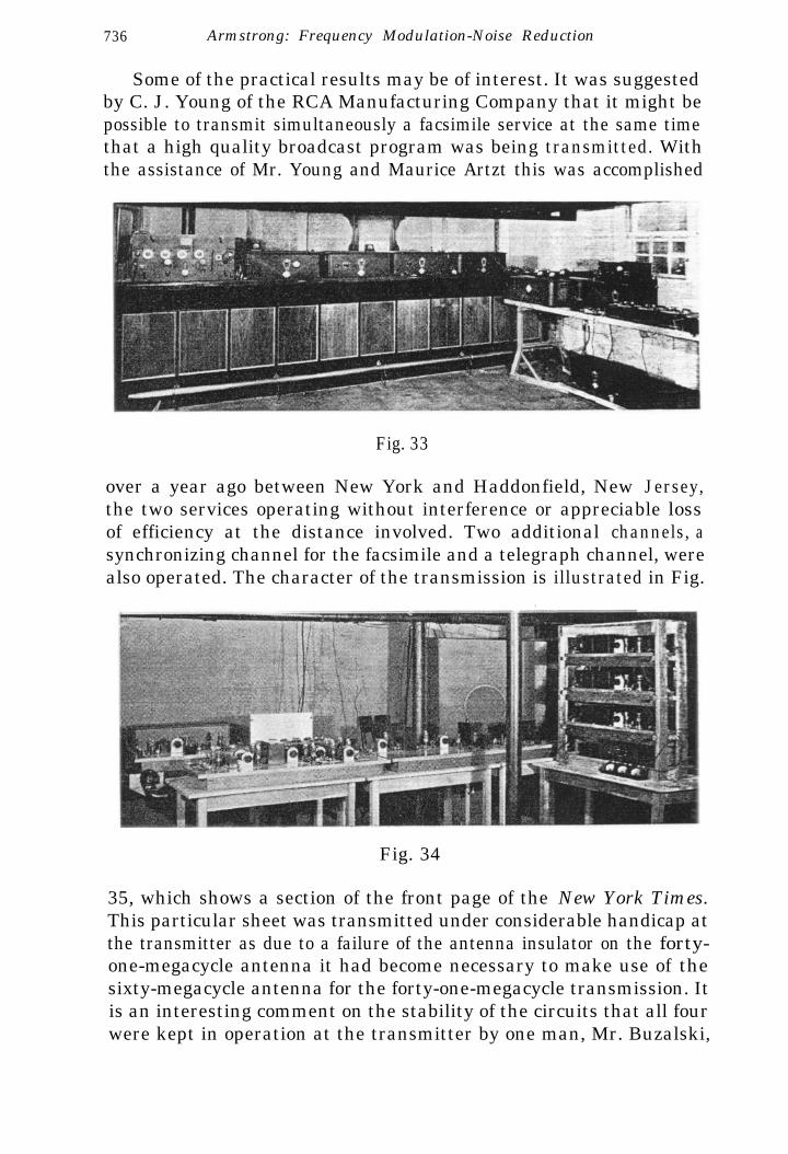
736 Armstrong: Frequency Modulation-Noise Reduction
Some of the practical results may be of interest. It was suggestedby C. J. Young of the RCA Manufacturing Company that it might bepossible to transmit simultaneously a facsimile service at the same timethat a high quality broadcast program was being transmitted. Withthe assistance of Mr. Young and Maurice Artzt this was accomplished
Fig. 33
over a year ago between New York and Haddonfield, New Jersey,the two services operating without interference or appreciable lossof efficiency at the distance involved. Two additional channels, asynchronizing channel for the facsimile and a telegraph channel, werealso operated. The character of the transmission is illustrated in Fig.
Fig. 34
35, which shows a section of the front page of the New York Times.This particular sheet was transmitted under considerable handicap atthe transmitter as due to a failure of the antenna insulator on the forty-one-megacycle antenna it had become necessary to make use of thesixty-megacycle antenna for the forty-one-megacycle transmission. Itis an interesting comment on the stability of the circuits that all fourwere kept in operation at the transmitter by one man, Mr. Buzalski,


738 Armstrong: Frequency Modulation-Noise Reduction
who was alone in the station on that day. The combined sound andfacsimile transmission has been in successful operation for about a year,practically perfect copy being obtained throughout the period of the
Fig. 36
Fig. 37
severe atmospheric disturbances of the past Summer. The subject ofthis work and its possibilities can best be handled by Mr. Young, whois most familiar with it.

Armstrong: Frequency Modulation-No&Reduction 739
ACKNOWLEDGMENT
On account of the ramifications into which this development en-tered with the commencement of the field tests many men assisted inthis work. To some reference has already been made.
I want to make further acknowledgment and express my indebted-ness as follows:
To the staff of the National Broadcasting Company’s stationW2XDG for their help in the long series of field tests and the conduct-ing of a large number of demonstrations, many of great complexity,without the occurrence of a single failure;
To Mr. Harry Sadenwater of the RCA Manufacturing Companyfor the facilities which made possible the Haddonfield tests and for hishelp with the signal-to-noise ratio measurements herein recorded;
To Mr. Wendell Carlson for the design of many of the transformersused in the modulating equipment;
To Mr. M. C. Eatsel and Mr. 0. B. Gunby of the RCA Manufactur-ing Company for the sound film records showing the comparison, atHaddonfield, of the Empire State transmission with that of the regularbroadcast service furnished by the New York stations;
To Mr. C. R. Runyon for his development of the two-and-one-half-meter transmitters and for the solution of the many difficult problemsinvolved in the application of these principles of modulation thereto;
To Mr. T. J. Styles and particularly to Mr. J. F. Shaughnessy, myassistants, whose help during the many years devoted to this researchhas been invaluable.
CONCLUSION
The conclusion is inescapable that it is technically possible to fur-nish a broadcast service over the primary areas of the stations of thepresent-day broadcast system which is very greatly superior to thatnow rendered by these stations. This superiority will increase as meth-ods of dealing with ignition noise, either at its source or at the receiver,are improved.
APPENDIX
Since the work which has been reported in this paper on forty-onemegacycles was completed attention has been paid to higher frequen- cies. On the occasion of the delivery of the paper a demonstration oftransmission on 110 megacycles from Yonkers to the EngineeringSocieties Building in New York City was given by C. R. Runyon, whodescribed over the circuit the transmitting apparatus which was used.A brief description of this transmitter is reproduced here.

740 Armstrong: Frequency Modulation-Noise Reduction
The power delivered to the antenna was approximately 100 wattsat 110 megacycles and the deviation (one half total swing) used duringthe demonstration was under 100 kilocycles. Fig. 36 illustrates themodulating equipment for this transmitter and the low power fre-quency multiplication stages. Fig. 37 shows the higher power frequencymultiplier and power amplifier stages of the transmitter.
The rack shown in Fig. 36 consists of six panels. Panel number, oneat the top contains the correction system. Panel number two containsthe master oscillator of 100 kilocycles and the modulator circuits. Panelnumber three contains a pair of doublers for multiplying the l00-kilo-cycle frequency to 400 kilocycles and the necessary filtering means foravoiding the modulation of the currents in the succeeding doublerstages by the l00-kilocycle oscillator current. Panel number four con-tains the doubljng apparatus for raising the frequency to 3200 kilocycleand panel number five the multipliers for raising it to 12,800 kilocycles.Panel number five also contains a heterodyning and conversion systemfor beating the 12,800 kilocycles down to 2292 kilocycles. Panel num-ber six contains a doubler for raising this to 4584 kilocycles and anamplifier for increasing the level sufficiently to drive the succeedingpower stage. The output of this amplifier is fed through a transmissionline to the metal box at the extreme right of Fig. 36 which contains aseries of doublers and amplifiers for increasing the level and raising thefrequency to 36,672 kilocycles. Adjacent to this box is a second boxwhich contains a fifty-watt amplifier. This amplifier drives a triplerlocated in the third box and the tripler in turn drives the power ampli-fier located at the extreme left at 110 megacycles. The transmitter cir-cuits were designed for total frequency swing of 500 kilocycles and maybe effectively so operated. Because of the limitation of the receiveravailable at that time the demonstration was carried out with a swingof 200 kilocycles.


![SCISCITATOR 2015 · [1]. Riverine communities experience two main types of disturbances: natural disturbances and anthropogenic disturbances. Natural disturbances in riverine ecosystems](https://static.fdocuments.in/doc/165x107/5f27dd3959f0c41da22eeec5/sciscitator-1-riverine-communities-experience-two-main-types-of-disturbances.jpg)


![A Method of Reducing Disturbances in Radio Signals … · ¤ 2¾ ' o ì _Mµô« 3Å s M5È [] Þ/&¬Qpé,uñ¥Ýý½ ë9 ÀS Es ` ... I.R.E., vol. 10, pp. 57-82; Armstrong: Frequency](https://static.fdocuments.in/doc/165x107/5bba36c609d3f2fb198d40e3/a-method-of-reducing-disturbances-in-radio-signals-2-o-i-mo-3a.jpg)