Hidden Noise. Strategies of Sound Montage in the Films of Hollis Frampton (2004)
Upload
hoangxuyenCategory
view
219download
4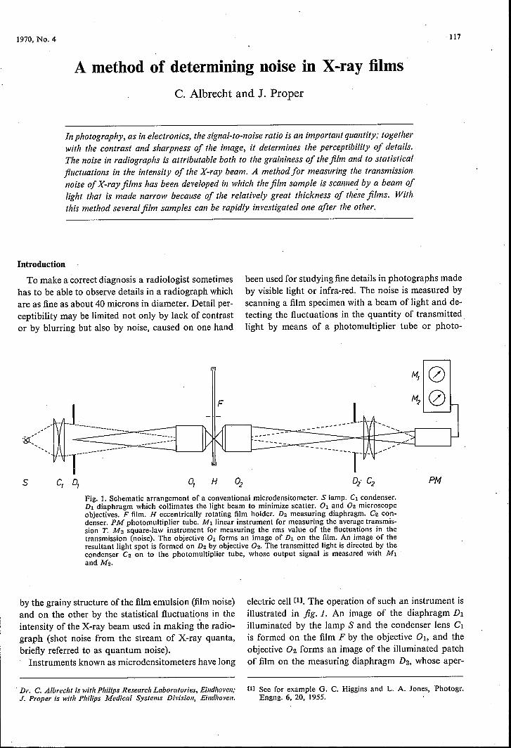
1970, No. 4
A method of determining noise in X-ray filmsC. Albrecht and J. Proper
In photography, as in electronics, the signal-to-noise ratio is an important quantity; togetherwith the contrast and sharpness of the image, it determines the perceptibility of details.The noise in radiographs is attributable both to the graininess of thefilm and to statisticalfluctuations in the intensity of the X-ray beam. A methodfor measuring the transmissionnoise of X-ray films has been developed in which thefilm sample is scanned by a beam oflight that IS made narrow because of the relatively great thickness of these films. Withthis method severalfilm samples can be rapidly investigated one after the other.
Introduetion
To make a correct diagnosis a radiologist sometimeshas to be able to observe details in a radiograph whichare as fine as about 40 microns in diameter. Detail per-ceptibility may be limited not only by lack of contrastor by blurring but also by noise, caused on one hand
F
5 Cl q H
been used for studying fine details in photographs madeby visible light or infra-red. The noise is measured byscanning a film specimen with a beam of light and de-tecting the fluctuations in the quantity of transmittedlight by means of a photomultiplier tube or photo-
PMFig. 1. Schematic arrangement of a conventional micro densitometer. S lamp. Cl condenser.Dl diaphragm which collimates the light beam to minimize scatter. 01 and 02 microscopeobjectives. F film. H eccentrically rotating film holder. D2 measuring diaphragm. C2 con-denser. PM photomultiplier tube. MI linear instrument for measuring the average transmis-sion T. M2 square-law instrument for measuring the rms value of the fluctuations in thetransmission (noise). The objective 01 forms an image of Dl on the film. An image of theresultant light spot is formed on D2 by objective 02. The transmitted light is directed by thecondenser C2 on to the photomultiplier tube, whose output signal is measured with MIand M2.
by the grainy structure ofthe film emulsion (film noise)and on the other by the statistical fluctuations in theintensity of the X-ray beam used in making the radio-graph (shot noise from the stream of X-ray quanta,briefly referred to as quantum noise).Instruments known as microdensitometers have long
. Dr. C. Albrecht is with Philips Research Laboratories, Eindhoven;J. Proper is with Philips Medical Systems Division, Eindhoven.
electric cell [11. The operation of such an instrument isillustrated in fig.1. An image of the diaphragm Dlilluminated by the lamp S and the condenser lens Clis formed on the film F by the objective 01, and theobjective 02 forms an image of the illuminated patchof film on the measuring diaphragm D2, whose aper-
[1] See for example G. C. Higgins and L. A. Jones, Photogr .Engng. 6, 20, 1955.
117

118 PHILlPS TECHNICAL REVIEW VOLUME 31
ture can be changed by changing the diaphragm. Toavoid scattered light, Dl is always made greater thanD2. The light transmitted by D2 is focused on to thecathode of the photomultiplier tube PM by the con-denser lens C2.If the film holder H is now made to rotate eccentric-
ally with respect to the optical axis, the light spot willdescribe a circular path on the film and the photomulti-plier tube will give an output signal which is propor-tional at every instant to the local transmission T of thefilm, averaged over the area of the light spot. The trans-mission, averaged over time, through the area of the
dimensions it is therefore still possible to use a scanningbeam whose cross-section at the film is only a fewmicrons. This can be a great advantage in measuringfilms of very fine structure, e.g. films for cartographyand microphotography.In radiography maximum absorption ofX-ray quan-
ta is required, and for this purpose the film base iscoated on both sides with a layer of emulsion, givingsuch a film a total thickness of 200 to 300 (.I.m. Thescanning beam used here therefore has to have a muchsmaller angular aperture. The fact that this entails lessreduction is not a disadvantage, since the smallest de-
Fig. 2. New arrangement for measuring noise in X-ray films. S mercury-vapour lamp witha light-emitting area of only 300 fLm cross-section (Philips type CS, 100 W). Cl condenser.D diaphragm. PI adjustable prism which causes the axis of the parallel light beam to coincidewith the optical axis of Land C2. P2 and Pa prisms, mounted in the sleeve K fixed to therotating shaft of M, the motor. L objective lens ("Xenotar" f /2.8; 150 mm). F film. H sta-tionary, adjustable film holder. B image of the diaphragm D. The image B can be varied indiameter steps by changing D, the minimum diameter is 40 fLm, the maximum diameterI mm. C2 condenser. G opal-glass disc, cemented to a rod of transparent plastic coated withA120a. PM photomultiplier tube. Mllinear-Iaw meter, and M2 root-mean-square meter. Somedimension~1 data: S-CISO mm. CI-D 350 mm. Optical path D-L 800 mm. L-Fabout 150mm.
film scanned by the light spot is measured with a linearinstrument Mi, and the effective value of the transmis-sion fluctuations is measured with an instrument M2which has a square-law characteristic. This effectivevalue is equal to the standard deviation aCT) of thetransmission T [2] and is a measure of the noise inten-sity. The ratio 'Ï'/aCT) then gives the signal-to-noiseratio of the transmission and can"be used; at a givencontrast, as the starting point for determining detailperceptibility.As the layer of emulsion on ordinary photographic
films has a thickness of the order of 10 (.I.m, the lightbeam used for scanning such films can have a largeangular aperture. In this way greatly reduced imagescan be obtained Careduction factor of 290 is no excep-tion). With a measuring diaphragm of reasonable
tails. of interest in an X-ray film are generally largerthan in the other photographic films mentioned.Another difference between the method of measure-
ment we have developed and the conventional micro-densitometer is that the light beam rotates and the filmholder is kept stationary. This facilitates quick changingof the film specimens and also makes it possible toinvestigate different zones on one specimen in rapidsuccession.
The measuring arrangement for X-ray films
The arrangement we have designed is shown sche-matically infig. 2. The light source S is a Philips typeCS 100 W mercury-vapour lamp. This lamp was spe-cially designed for measurement and projection pur-poses, and has a light-emitting area with a diameter of

1970, No. 4 NOISE IN X-RAY FiLMS
only 0.3 mm. The condenser Cl forms the light fromthe mercury lamp into a practically parallel beam,which is directed on to the interchangeable round dia-phragm D. The aperture of this diaphragm can bevaried in steps from 0.2 mm to 6 mm. The transmittedlight beam is reflected by the adjustable prism PI insuch a way that the beam axis coincides with the optical .axis of the lens system L-C2. From the prisms P2 andP3 the beam then goes to a lens L, anf/2.8 "Xenotar"objective with a focal length of 150 mm, which pro-duces a 6 times reduced image of the diaphragm on thefilm F. The prisms P2 and P3 are mounted in a sleeve Kconnected to the shaft of the motor M. When the shaftrotates, the light spot describes a circular path on thefilm F. The light beam rotates at a speed of 25 revolu-tions per second, the diameter of the circular path is35 mm. By changing D the diameter of the light spoton the film can be varied from 40 [Lm to 1 mm. Thespecimens of the film under investigation can simplybe inserted in the stationary film holder H, without themotor having to be stopped, which is necessary in themicrodensitometer in fig. 1. Moreover the film holdercan be adjusted in three directions, lengthwise for goodfocusing, and horizontally or vertically for examiningdifferent parts of the film.
The light passing through the film is directed by thecoridenser lens C2 on to an opal glass disc. This isconnected to the window of the photomultiplier tubePM by a plastic rod coated with Ah03, so that thelight is diffusely distributed over the photocathode ofthe photomultiplier tube. This ensures that changes inthe diameter and point of incidence of the beam haveno effect on the output signal, which would otherwisebe affected by local differences in the sensitivity of thephotocathode. As in the micro densitometer of fig. 1,f and aCT) are measured by means of meters MI andM2. It has been found that an axial displacement of thefilm holder by 1 mm in either direction has hardly anyeffect on the results, indicating that the depth of focusis sufficient to measure relatively thick X-ray filmsaccurately:
Comparison of the measured transmission noise with thequantum noise
The noise measured by the method described is acombination of film noise and 'quantum noise. -Theshare of the quantum noise can be determined separ-ately in the following way. Ameasurement is made ofthe exposure [3] needed to produce a predeterrninedblackening of the film. This exposure and the quan-turn energy give the number of quanta incident on unitarea of the film; this number is called the fluence, <P.The fluence and the absorption coefficient of the film, a,which is determined from the mass-absorption coef-
119
ficient of the silver bromide in the film emulsion andthe mass óf AgBr per ni2, give the number of quantaabsorbed per unit area, r:x<P.Since the quantum noisefollows a Poisson distribution, the standard deviationor noise related to a surface area of diameter d is:
a(a<J»)= td Vr:xn!P, (1)
and the signal-to-noise ratio is:
tnd2a<J) ,~=tdVr:xn!p.-id
Both quantities are in this case equal.In order to compare the measured signal-to-noise
ratio of the transmission with that which .is caused bythe quantum noise, it is desirable to express the trans-mission fluctuations in terms of equivalent fluence flue-tuations.
To do this we must take the roundabout route ofusing the characteristic curve of the film. This gives therelationship between the density D, i.e. the blackeningof the film, and the logarithm of the fluence <P (seefig. 3). The density is defined as the negative logarithmof the transmission T:
D = -IOglO T.
(2)
3,-----------------------.------,(3)
o
r2
•. 2 ,-log <P
3
Fig. 3. Typical characteristic curve of an X-ray film, showing thedensity D plotted against the logarithm of the f1uence W. Thegradation y of the film is the' tangent of the slope of the curve (J.Unlike the- characteristic curve -obtained on irradiation withvisible light, the curve shown in this figure has no linear region.The gradation increases with increasing density. -
[21 For; continuously varying transmission the standard devia-21fr _
tion a(T) is equal to {f (T - T)2 dx/271r p/2, where 2r is.0
the diameter of the scanning track. This expression is equi-valent to the rms value of T,measured over the circular path.
[31. This quantity used to be called the exposure dose; see, for.example, J. Hesselink and K. Reinsma, Philips tech. Rev. 23,56, 1961/62. . . ' .

120 PHILIPS TECHNICAL REVIEW VOLUME 31
The gradation of the film, i.e. the steepness of itscharacteristic curve, is given by dD/d log lO(IJ= tan fland is denoted by the symbol y [4]. From (3) it canbe shown that
dD d T (IJY = =--.-. (4)
d 10glO(IJ . d <IJ T
In all parts of the film, therefore, a relative increaseiJT/T of the transmission is associated with a relativedecrease iJ (IJ/ij) in the fluence, which is given by:
iJ (IJ liJTij) =-y T .
Here T and ij) represent the average values of the trans-mission and fluence that relate to the background. Wemay therefore write:
(aeq«(IJ») = ~(a<!») "
<IJ dY t r;where the subscript d indicates that the measurementswere made for surface area of diameter d. The quantityaeq(<IJ) is the' "equivalent" standard deviation of thefluence that the measured standard deviation of thetransmission would cause if all the noise were due tothe X-ray beam. We can now compare quantum noiseand film noise in quantitative terms.If a particular detail with the relative contrast iJT/T
is to be perceptible against a background of transmis-sion T, then iJT/T must be at least three times the valueof aT/T [5]. Together with equation (6) this gives:
{t1>/aeq«(IJ)}d~ 3 yT/iJT.
We have thus found an expression for the minimumvalue of the equivalent signal-to-noise ratio of thefluence at which a detail with a particular transmissioncontrast is-still perceptible.
In order to be able to calculate the signal-to-noiseratio with the aid of (7) we still have to determine thevalue of y at the given density. To measure tan flfrom the density increment accompanying a slightincrease in 10glO <IJ would not be accurate enough.For this reason, and also to avoid errors due to theCallier effect, we have devised a method of measure-ment in which the noise meter itself is used for deter-mining y. An -underlying principle of this method isthat the accuracy of a measurement is increased byfrequent repetition of the observation.
For the determination of y we start by making a test pattern.A lead wheel with about thirty spokes and an inside diameter alittle greater than the diameter of the track scanned by the noisemeter is placed on a strip of film. After the piece of film has beenexposed to X-rays and developed, a high-contrast image of the
(5)
spoked wheel is obtained. When the strip is scanned with thenoise meter the light spot illuminates in turn the exposed partsof the film and the unexposed parts where the spokes were, givinga measurement of the root-mean-square (rms) variation of thetransmission. A static measurement at and between the "spokes"gives the peak-to-peak value. From this the calibration constantof the noise meter is found, and with this constant we can thustranslate a root-mean-square value into a contrast.To measure the noise and determine the y of a film the spoked
wheel is now placed on a test strip of the film and a short expo-sure is made. The wheel is then removed and the test strip isexposed again until the parts of the film outside the spokes ofthe wheel reach the required density on developing. The initialexposure time is chosen so as to give a relatively small contrastbetween the spokes and the rest of the film (5 to 10% differencein transmission). When the image of the wheel is scanned withthe noise meter in the way described above, the rms value of thetransmission variations and the knowledge of the calibrationconstant give an accurate indication of the difference in contrastcaused by a known small change in exposure. From this thevalue of y can be calculated. The noise measurement is madeon another part of the test strip.(6)
(7)
Some results obtained with the new method
Fig. 4 shows the results of measurements on twotypes of X-ray film, one for industrial use (Gevaerttype D4) and one for qedical use (Gevaert type DI 0).The equivalent signal-to-noise ratio of the fluence{ij)/O'eq(<IJ)}dis plotted as a function of the diameterof the scanning spot, both on a logarithmic scale fora density D = 1.75 (solid curves). The measurementswere done with X-rays with rms quantum energies of32 keY and 105 keY. The radiation was so closelyfiltered that for our purposes it may be regarded asmonochromatic. The dashed curves give the value ofthe signal-to-noise ratio expressed as the number ofabsorbed X-ray quanta, calculated from (2). This quan-tity is equal to the value of {ij)/O'eq((IJ)}d that wouldbe found if the transmission fluctuations were causedsolely by the spatial statistical fluctuations in the dis-tribution of the incident radiation and by the absorp-tion processes in the film.
As can be seen in fig. 4, the equivalent signal-to-noiseratio of the transmission is virtually equal to that ofthe quantum noise for both films. Moreover the differ-ence lies within the margin of error in the calculationofthe quantum noise. One may therefore conclude thatthe limiting factor for both films is the quantum noise,since no higher value of the signal-to-noise ratio canbe measured on the film than that determined by thequantum noise. From what we have said it follows thatthe resolution of our noise meter is more than sufficientto determine the noise in the very fine-grained D4 film.The instrument is therefore certainly suitable for meas-uring the usually rather faster and coarser films formedical applications.

1970, No. 4 NOISE IN X-RAY FiLMS 121
Fig. 4. Signal-to-noise ratio as afunction of the diameter d of thescanning spot for Gevaert films D4and Dl 0 at two quantum-energyvalues. The film density D was inall cases I.75. Solid lines: signal-to-noise ratio {ëP/ucq(CP)}a ofthefluenceobtained from transmission meas-urements. Dashed curves: signal-to-noise ratio calculated from d, thefluence cp and the absorption coef-ficient ex. Apart from slight differen-ces probably due to inaccuracy in.the data used for calculating thequantum noise, the measured signal-to-noise ratio is identical with thecalculated values in all cases. Thisimplies that in this case the resolu-tion is determined by the quantumnoise.The horizontal chain-dotted lines
give the value of the signal-to-noiseratio required for details with arelative transmission contrast of2 %and 10% to be perceived. For ex-ample, the circle indicates that fora D4 film with X-radiation of 32keY and a contrast of 2%, detailswith a diameter of 250 ILmare stillperceptible.
5
32keV
IJT-=0.02 -.-.-.-._.T
5
2
LlT =010T .
D=1.75
W~ __~ ~ __~~ __~ ~~~~~~ __~10 2 5 100 2 5 WOOurn
-d
It might appear that, as long as the film noise is lower than thequantum noise, the film could be made coarser to increase itsspeed. In this case, however, the number of quanta required fora particular density will be less, so that the signal-to-noise ratiowill be lower. This can be seen clearly for the Gevaert DI0 film,which is 30 times faster than the D4 film and has emulsion layerstwice as thick, thus requiring 15 times as many quanta to producethe same density. The signal-to-noise ratio would thus have tobe a factor of Vl5 smaller, and this is confirmed by the measure-ments.
Another thing shown by fig. 4 is that the signal-to-noise ratio is proportional to the diameter ofthe scan-ning spot: this also follows from equation (2).
For radiation with a quantum energy of 105 keY thesignal-to-noise ratio is smaller than for radiation of32 keV, because fewer quanta of 105 keY are neededto produce a given density.
One further and final conclusion can be drawn fromfig. 4. The smallest transmission contrast iJTjf' that isstill perceptible to the eye is about 2%. It follows thenfrom (7) that for y = 2.5, the value of {iJ)jaeq(([J)}dmust be at least 375 if details with a diameter of about
[4] For a more detailed treatment of the properties of X-rayfilms, see D. H. O. John, Radiographic processing in medi-cine and industry, The Focal Press, London 1967.
[5] T. Tol, W. J. Oosterkamp and J. Proper, Limits of detailperceptibility in radiology particularly when using the imageintensifier, Philips Res. Repts. 10, 141-157, 1955.
[6] C. Albrecht and J. Proper, Medicamundi 11, 44, 1965, par-ticularly fig. 1. .
250 [Lm on the D4 film and about 800 [Lm on the DlOfilm are to be perceived at an energy of 32 kev., For acontrast of 10% the D4 film gives a minimum detailsize of about 50 [Lm and the DlO film one of about150 [Lm at this quantum energy (lower horizontalchain-dotted line).
This method of measurement has also been used forX-ray films that are used with a fluorescent layer pressedagainst each side during the exposure, a technique usedto increase the sensitivity of the emulsion layers [6]
and reduce the X-ray dose. Our method can also beused for determining noise in radiographs obtained withthe aid of an X-ray image intensifier.
Summary. The noise in a radiograph is due not only to the quan-tum noise of the X-ray beam but also to the grainy structure ofthe film emulsion. This film noise can be a limit to the qualityof the radiograph and thus reduce its usefulness for diagnosis.A simple method has been developed for measuring the signal-to-noise ratio of X-ray films. It uses a rotating beam of lightof small angular aperture which scans a stationary film specimenalong a circular path. The small angular aperture gives a sufficientdepth of focus for the measurement ofrelatively thickX-ray films(thickness about 0.3 mm). The use of a stationary film holdermakes it possible to change film specimens quickly and to measuredifferent parts of films in rapid succession. One interesting resultofmeasurements by this method is that the signal-to-noise ratioof type D4 and DIO Gevaert films has been found to be limitedby quantum noise. The method can also be used for measuringthe noise characteristic of radiographs taken with the aid of anX-ray image intensifier.
122 PHILIPS TECHNICAL REVIEW VOLUME 31
Recent 'scientific publicationsThese publications are contributed by staff of laboratories and plants which form partof or co-operate with enterprises of the Philips group of companies, particularly by staffof the following research laboratories:
Philips Research Laboratories, Eindhoven, Netherlands EMullard Research Laboratories, Redhill (Surrey), England MLaboratoires d'Electronique et de Physique Appliquée, Limeil-Brévannes (Val-
de-Marne), France LPhilips Forschungslaboratorium Aachen GmbH, WeiBhausstraBe, 51 Aachen,
Germany APhilips Forschungslaboratorium Hamburg GmbH, Vogt-Kölln-Straûe 30,
2000 Hamburg 54, Germany 'HMBLE Laboratoire de Recherches, 2 avenue Van Becelaere, 1170 Brussels
(Boitsfort), Belgium. B
Reprints of most of these publications will be available in the near future. Requests forreprints should be addressed to the respective laboratories (see the code letter) or to PhilipsResearch Laboratories, Eindhoven, Netherlands.
W. Albers & J. Verberkt: The SnSe-SnSe2 eutectic; aP-N multilayer structure.J. Mat. Sci. 5, 24-28, 1970 (No. I). E
D. Andrew, J. P. Gowers, J. A.Henderson, M. J. Plum-mer, B. J. Stocker & A. A. Turnbull: A GaAs-Cs-Otransmission photocathode.J. Physics D 3, 320-326, 1970 (No. 3). M
R G. M. Bax: Analysis of the FM receiver with fre-quency feedback.Thesis, Nijmegen 1970. . E
V. Belevitchr.Interpolation matrices.Philips Res. Repts. 25, 337-369, 1970 (No. 5). B
F. Berz: Theory of low frequency noise in Si MOST's.Solid-State Electronics 13, 631-647, 1970 (No. 5). M
G. Blasse: Structure and luminescence of MgGaB04.J. inorg. nucl. Chem. 32, 700, 1970 (No. 2). E
G. Blasse: -Luminescence of the tungstate group In
scheelite and fergusonite.Philips Res. Repts. 25, 231-236, 1970 (No. 4). E
G. Blasse & A. Bril: Some observations on the lumines-cence of {J-Ga203.J. Phys. Chem. Solids 31, 707-711, 1970 (No. 4). E
I.
M. T. Borchert & J. S. C. Wessels: Combined prepara-tion of ferredoxin, ferredoxin-Ná.Dl>+ reductase andplastocyanin from spinach leaves.Biochim. biophys. Acta 197, 78-83, 1970 (No. I). E
C. J. Bouwkamp: Determination of the characteristicof a non-linear resistor by harmonic excitation.Ingenieur 82, ET 1-2, 1970 (No. 5). E
C. J. Bouwkamp & D. A. Klarner (Technical-Universityof Eindhoven): Packing a box with Y-pentacubes ..J. recreat. Math:3; 10-26, 1970{No. 1). E
K. H. J. Buschow: The erbium-copper system.Philips Res. Repts. 25, 227-230, 1970 (No. 4). E
K. H. J. Buschow & H. J. van Daal: Investigations onthe resistivity of the compound CeAla.Solid State Comm. 8, 363-365, 1970 (No. 5). E
K. H. J. Buschow & A. S. van der Goot: The crystalstructure of some copper compounds of the type RCu6.J. less-common Met. 20, 309-313, 1970 (No. 4). E
H. B. G. Casimir: On supergain antennae.Philips Res. Repts. 25, 237-243, 1970 (No. 4). E
M.C. Collet: Recombination-generation centers causedby 60°-dislocations in silicon.J. Electrochem. Soc. 117, 259-261, 1970 (No. 2). E
C. Crevecoeur & H. J. de Wit: Electrical conductivityof Li doped MnO.J. Phys. Chem. Solids 31, 783-791, 1970 (No. 4). E
H. J. van Daal & K. H. J. Buschow: Anomalous beha-viour of the electrical resistivity in the compoundCe3AIll.Physics Letters 31A, 103-104, 1970 (No. 3). E
H. Dammann: Blazed synthetic phase-only holograms.Optik 31,95-104, 1970 (No. I). H
R. Dändliker & K. Weiss: Reconstruction of the three-dimensional refractive index from scattered waves.Optics Comm. 1, 323-328, 1970 (No. 7). E
M. Davio: Extremal solutions of unate Boolean equa-tions.Philips Res. Repts. 25, 201-206, 1970 (No. 4). B
M. Davio & G. Bioul: Representation of lattice func-tions. . .'Philips Res. Repts. 25, 370-388, 1970 (No. 5). B

1970, No. 4 RECENT SCrENTrFIC PUBLICATIONS 123
P. Delsarte: Automorphisms of abelian codes.Philips Res. Repts. 25, 389-403, 1970 (No. 5). B
J. C. DieIs: Light pulse propagation in homogeneouslybroadened amplifiers.Physics Letters 31A, 26-27, 1970 (No. I). E
J. C. DieIs: Self induced transparency in near resonantmedia.Physics Letters 31A, 111-112, 1970 (No. 3). E
A. M. van Diepen (Natuurkundig Laboratorium derUniversiteit van Amsterdam), K. H. J. Buschow &H. W. de Wijn (Natuurk. Lab. Univ. Amst.): Nuclearmagnetic resonance and magnetic susceptibility ofPr3Aln, Nd3Aln, and EuAI4.J. chem. Phys. 51, 5259-5263, 1969 (No. 12). E
P. Dolizy & R. Legoux: A new technology for trans-ferring photocathodes.Adv. in Electronics and Electron Phys. 28A, 367-373,1969. L
H. C. Donkersloot & J. H. N. van Vucht: Martensitictransformations in gold-titanium, palladium-titaniumand platinum-titanium alloys near the equiatomic corn-position.J. less-common Met. 20, 83-91, 1970 (No. 2). E
G. Eschard & J. Graf: Quelques problèmes concer-nant les multiplicateurs canalisés pour intensificateurd'image,Adv. in Electronics and Electron Phys. 28A, 499-506,1969. L
G. Eschard & R. Polaert: Tubes obturateurs pour pho-tographie ultra-rapide au temps de pose d'une nano-seconde.Adv. in Electronics and Electron Phys. 28B, 989-998,1969. L
K. G. Freeman, R. N. Jackson, P. L. Mothersole(Mullard Central Appl. Lab., Mitcham, England) &S. J. Robinson: Some aspects of direct television recep-tion from satellites.Proc. lEE 117, 515-520, 1970 (No. 3). M
A. A. van der Giessen: De hydrothermale bereiding vankeramische poeders.Klei en Keramiek 20,. 30-38, 1970 (No. 2). E
W. J. A. Goossens & D. Polder: Size effects in theresonances of nonlocal helicon waves.Phys. Rev. 187, 943-950, 1969 (No. 3). E
A. D. C. Grassie (School of Math. and Phys. Sci.,Univ. of Sussex, Brighton, UK) & D. B. Green: Tran-sition anomalies of disordered aluminium films.Physics Letters 31A, 135-136, 1970 (No. 3). E
C. A. A. J. Greebe: Enhancement of the interactionbetween an acoustic surface wave in a piezoelectric anda drifted electron gas by means of a magnetic field ..Physics Letters 31A, 16-17, 1970 (No. I). E
G. Groh & G. W. Stroke (State University of NewYork, Stony Brook, N.Y.): Information retrieval fromcoded images formed by generalized imaging systems.Optics Comm. 1, 339-340, 1970 (No. 7). H
E. E. Havinga & M. H. van Maaren: Superconductivityand band structure.Physics Letters 31A, 167-168, 1970 (No. 4). E
E. E. Havinga, J. H. N. van Vucht & K. H. J. Buschow:Reply to the comments of K. A. Gschneidner (pp.255-256, on the paper "Relative stability of variousstacking orders in close-packed metal structures" J.Philips Res. Repts. 25, 257-258, 1970 (No. 4). E
H. F. van Heek: Emission profile of the Mg resonanceline by Zeeman scanning.Spectrochim. Acta 25B, 107-109, 1970 (No. 2). E
B. J. Hoetink (Philips Glass Division, Eindhoven):Process dynamics of a glass furnace following a stepchange of one of the batch components.Glass Technol. 10, 84-89, 1969 (No. 3).
E. P. Honig & J. H. Th. Hengst: Current/voltage curvesof BaS04 membranes.Electrochim. Acta 15, 491-499, 1970 (No. 3). E
J. T. Klomp & Th. P. J. Botden: Sealing pure aluminaceramics to metals.Amer. Ceramic Soc. Bull. 49, 204-211, 1970 (No. 2). E
H. Levine (Dept. of Mathematics, Stanford Univ.,Cal.): Some problems in potential theory ..Philips Res. Repts. 25, 207-222, 1970 (No. 4).
F. A. Lootsma & J. D. Pearson (Philips InformationSystems and Automation Division, Eindhoven): Anindefinite-quadratic-programming model for a con-tinuous-production problem.Philips Res. Repts. 25, 244-254, 1970 (No. 4). E
J. Monin (Conservatoire National des Arts et Métiers,Paris), J. Houdard & G.-A. Boutry (Cons. Nat. A. etM.): Détermination des constantes optiques du césiumdans Ie visible et dans Ie proche ultraviolet.C.R. Acad. Sci. Paris 270B, 279-282, 1970 (No. 4). L
K. Mouthaan: Niet-lineariteit van de lawine-Iooptijd-oscillator.Ingenieur 82, ET 4-7, 1970 (No. 5). E
M. Noé: Problèmes d'interconnexion optimale (2epartie).Rev. MBLE 12, 117-132, 1969 (No. 4). B
B. Patemostre & P. Wodon: Description et applica-tions d'un générateur de macros.Rev. MBLE 12, 133-151, 1969 (No. 4). . B
R. Plumier (Centre d'Etudes Nucléaires de SacIay,France) & F. K. Lotgering: Antiferromagnetic inter-. actions between Fe3+ ions at a large distance inFel/2CUl/2Rh2S4.Solid State Comm. 8, 477-480, 1970 (No. 6). . E

124 PHlLIPS TECHNICAL REVlEW VOLUME 31
A. Rabenau, H. Rau & G. Rosenstein: Über Chalko-genidhalogenide des Kupfers.Z. anorg. allgem. Chemie 374,43-53, 1970 (No. I). A
J. E. Ralph: Optical transitions in Tm3+ dopedy3Ga5012 near 2.0 (.L.Solid State Comm. 7, 1065-1067, 1969 (No. 15). M
J. E. Ralph & T. L. Tansley: Photoelectric effects incadmium sulphide MIS devices.J. Physics D 3, 620-623, 1970 (No. 4). M
H. D. Rüpke: Magnetodynamic modes in ferrite spheresfor microwave filter application.IEEE Trans. ~G~6, 80_:-84,1~70 (No. I). H
U. J. Schmidt & W., Thust: Temperature stabilisationof the deflection pattern of a digitallight deflector con-taining single prisms.Opto-electronics 2, 29-35, 1970 (No. I). . H
J. Schröder & F. J. Grewe: Darstellung und Eigen-schaften von Wolframpentafluorid.Chem. Berichte 103, 1536-1546, 1970 (No. 5). A
E. Schwartz: Die Bandbreite von Anpassungsvierpolenmit zwei Reaktanzen.Archiv elektro Übertr, 24, 179-186, 1970 (No. 4). A
H. Schweppe: Excitation of two adjacent resonanceswith a chosen frequency separation in a ceramic piezo-electric resonator.IEEE Trans. SU-17, 12-17, 1970 (No. I). A
J. M. Shannon, R. Tree & G. A. Gard (Atomic EnergyResearch Establishment, HarweIl, England): Electricalcharacteristics of ion implanted boron layers in silicon.Can. J. Phys. 48, 229-235, 1970 (No. 2). M
L. A. IE. Sluyterman & M. J. M. de Graaf: Thefluorescence of papain.Biochim. biophys. Acta 200,595-597, 1970(No. 3). E
L. A. IE. Sluyterman & J. Wijdenes: An agarose mer-curial column for the separation of mercaptopapainand nonmercaptopapain.Biochim. biophys. Acta 200, 593-595, 1970(No. 3). E
T. L. Tansley & J. E. Ralph: Photoeffects in met al-insulator-gallium arsenide diodes.J. Physics D 3, 807-811, 1970(No. 5). M
A. Thayse: Transient analysis of logical networks ap-plied to hazard detection.Philips Res. Repts. 25, 261-336, 1970 (No. 5). B
K. Timling: Scaled-particle theory of two-dimensionalanisotropic fluids.Philips Res. Repts. 25, 223-226, 1970 (No. 4). E
H. J. L. Trap: Les effets de quelques traitements con-ventionnels sur la conductibilité superficielle du verre.Verres et Réfr. 23, 28-37, 1969 (No. I). E
T. S. te Velde: Mono-grain layer solar cells.Performance forecast of selected static energy conver-sion devices, 29th Meeting of AGARD Propulsion andEnergetics Panel, Liège 1967,pp. 927-941. E
F. F. Westendorp: On the coercivity of SmC05.Solid State Comm. 8, 139-141, 1970 (No. 3). E
M. V. Whelan: Electrical behaviour of defects at athermally oxidized silicon surface.Thesis, Eindhoven 1970. E
Contents of Mullard Technical Cornmunications 11, No. 108, 1970:
A. J. Guest: Channel multiplier plates for image intensification (pp. 170-176).J. Wickens: 15W class A audio amplifier (pp. 177-178).R. F. Mitchell, R. G. Pratt, J. S. Singleton & W. Willis: Surface wave filters (pp. 179-181).M. H. Jervis & F. D. Morten: Mercury cadmium telluride infrared detectors, at 5 (.Lmand normal ambienttemperature (pp. 182-184).
Contents ofValvo Berichte 16, No. 1, 1970:
F. Weitzsch: Farbabweichungen als Folge von Exemplarstreuungen im Farbart-Teil von Farbfernseh-Empfän-gern (pp. 1-12).B. J. M. Overgoor: Ein Operationsverstärker mit Feldeffekt-Transistoren in der Eingangsstufe (pp. 13-33).Schliffbild eines Sperrschicht- Feldeffekt-Transistors (pp. 34-35).
Volu me 31, 1970, No. 4 Published 4th May 1971pages 97-124

PHILIPS TECHNICAL REVIEWVOLUME 31, 1970, No. 5/6 -------------
One of our most loyal readers has recently celebrated the 40thanniversary of his joining Philips on 1st December 1930. Anni-versaries do not usually receive any attention in our pages, but wefeel that this one is rather special, since the reader we have in mi~d,one of the founders of our Review, is the President of the groupof companies that bears his name. The photograph above showsour President (on the left) and Dr. Rinia, the former director ofPhilips Research Laboratories, looking at an experimental Stirlingmotor for heavy traction work. We join the authors in preserz"ii~ito Ir. F. J. Philips this issue, whose articles are all on subjectsthat have attracted his special interest.
126 PHILlPS TECHNfCAL REVIEW VOLUME 'I
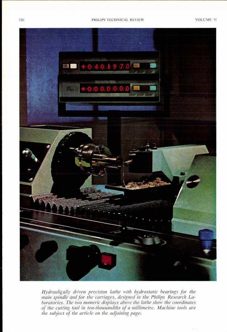
Hydrauliçally driven precision lathe with hydrostatic bearings for themain spindle and for-the carriages, designed in the Philips Research La-boratories. The two numeric displays above the lathe show the coordinatesof the cutting tool in ten-thousandths of a millimetre. Machine tools arethe subject of the article on the adjoining page.