A Method for Analyzing Effects of Dam Failures in Design ...
36
US Army Corps of Engineers Hydrologic Engineering Center A Method for Analyzing Effects of Dam Failures in Design Studies August 1972 Approved for Public Release. Distribution Unlimited. TP-39
Transcript of A Method for Analyzing Effects of Dam Failures in Design ...

US Army Corps of Engineers Hydrologic Engineering Center
A Method for Analyzing Effects of Dam Failures in Design Studies August 1972 Approved for Public Release. Distribution Unlimited. TP-39

Standard Form 298 (Rev. 8/98) Prescribed by ANSI Std. Z39-18
REPORT DOCUMENTATION PAGE Form Approved OMB No. 0704-0188
The public reporting burden for this collection of information is estimated to average 1 hour per response, including the time for reviewing instructions, searching existing data sources, gathering and maintaining the data needed, and completing and reviewing the collection of information. Send comments regarding this burden estimate or any other aspect of this collection of information, including suggestions for reducing this burden, to the Department of Defense, Executive Services and Communications Directorate (0704-0188). Respondents should be aware that notwithstanding any other provision of law, no person shall be subject to any penalty for failing to comply with a collection of information if it does not display a currently valid OMB control number. PLEASE DO NOT RETURN YOUR FORM TO THE ABOVE ORGANIZATION. 1. REPORT DATE (DD-MM-YYYY) August 1972
2. REPORT TYPE Technical Paper
3. DATES COVERED (From - To)
5a. CONTRACT NUMBER
5b. GRANT NUMBER
4. TITLE AND SUBTITLE A Method for Analyzing Effects of Dam Failures in Design Studies
5c. PROGRAM ELEMENT NUMBER
5d. PROJECT NUMBER 5e. TASK NUMBER
6. AUTHOR(S) William A. Thomas
5F. WORK UNIT NUMBER
7. PERFORMING ORGANIZATION NAME(S) AND ADDRESS(ES) US Army Corps of Engineers Institute for Water Resources Hydrologic Engineering Center (HEC) 609 Second Street Davis, CA 95616-4687
8. PERFORMING ORGANIZATION REPORT NUMBER TP-39
10. SPONSOR/ MONITOR'S ACRONYM(S) 9. SPONSORING/MONITORING AGENCY NAME(S) AND ADDRESS(ES) 11. SPONSOR/ MONITOR'S REPORT NUMBER(S)
12. DISTRIBUTION / AVAILABILITY STATEMENT Approved for public release; distribution is unlimited. 13. SUPPLEMENTARY NOTES Presented at the ASCE Hydraulics Division Specialty Conference, Cornell University, August 1972. 14. ABSTRACT In the planning and design of dams and embankments for large multiple-purpose projects, it is usually necessary to evaluate the effect of potentially disastrous extreme events to insure that the proposed developments do not produce an unnecessary increase in the disaster potential. One such case which is being encountered more frequently now involves the design of dams and embankments for projects located downstream from an existing dam. If the existing structure is relatively old or if there is reason to believe that the probability of failure is relatively great, it may be desirable to consider the effect of a potential failure during the design of the downstream structure. In the design studies for a dam to be located downstream from an existing dam, the effects of failure of the upstream structure have been calculated. The flood wave which would result from failure of the upstream dam has been calculated and routed through the reservoir that would be formed by the downstream structure. The analysis utilized the unsteady flow equations to evaluate the effect of the flood wave under three different conditions of impoundment in the downstream reservoir at the time of failure. The structure that was assumed to fail was treated as a finite discontinuity in the water surface elevation at an internal point in the computation net rather than as a boundary condition. The design, verification and use of the digital simulation model for the analysis are presented. 15. SUBJECT TERMS dam design, dam failure, flood waves, model studies, design flood, flood routing, reservoir capacity, wave energy, energy loss, hydrostatic pressure, unsteady flow, kinetic energy, gradually varied flow, calculations, evaluation, hydraulic pressure, Hydrologic Engineering Center, flood hydrographs, pressure distribution, impact loads 16. SECURITY CLASSIFICATION OF: 19a. NAME OF RESPONSIBLE PERSON a. REPORT U
b. ABSTRACT U
c. THIS PAGE U
17. LIMITATION OF ABSTRACT UU
18. NUMBER OF PAGES 36 19b. TELEPHONE NUMBER

A Method for Analyzing Effects of Dam Failures in Design Studied
August 1972 US Army Corps of Engineers Institute for Water Resources Hydrologic Engineering Center 609 Second Street Davis, CA 95616 (530) 756-1104 (530) 756-8250 FAX www.hec.usace.army.mil TP-39

Papers in this series have resulted from technical activities of the Hydrologic Engineering Center. Versions of some of these have been published in technical journals or in conference proceedings. The purpose of this series is to make the information available for use in the Center's training program and for distribution with the Corps of Engineers. The findings in this report are not to be construed as an official Department of the Army position unless so designated by other authorized documents. The contents of this report are not to be used for advertising, publication, or promotional purposes. Citation of trade names does not constitute an official endorsement or approval of the use of such commercial products.

A METHOD FOR ANALYZING EFFECTS OF DAM FAILURES
IN DESIGN STUDIES")
by William A, Thomas (2)
ABSTRACT
In the planning and design of dams and embankments for large
multiple-purpose projects, it is usually necessary to evaluate the
effect of potentially disastrous extreme events to insure that the pro-
posed developments do not produce an unnecessary increase in the
disaster potential. One such case which is being encountered more
frequently now involves the design of dams and embankments for projects
located downstream from an existing dam. If the existing structure is
relatively old or if there is reason to believe that the probability
of failure is relatively great, it may be desirable to consider the
effect of a potential failure during the design of the downstream
structure.
In the design studies for a dam to be located downstream from an
existing dam, the effects of failure of the upstream structure have been
calculated. The flood wave which would result from failure of the up-
stream dam has been calcul.ated and routed through the reservoir that
wou1.d be formed by the downstream structure. The analysis utilized the
or presentation at the ASCE Hydraulics Division Specialty Conference, Cornell University, August 1972
'2)~esearch Hydraulic Engineer, Research Branch, The Hydrologic Engineering Center, U. S, Army Corps of Engineers, Davis, California

unsteady flow equations to evaluate the effect of the flood wave under
three different conditi.ons of impoundment in the downstream reservoir
at the time of failure. The structure that was assumed to fail was
treated as a finite discontinuity in the water surface elevation at
an internal point in the computation net rather than as a boundary
condition. The design, verification and use of the digital simulation
model for the analysis are presented.
A METHOD FOR AMALYZING EFFECTS OF DAM FAILURES
IN DESIGN STUDIES
by William A. Thomas (2)
In recent years , the f a i l u r e s of s e v e r a l s m a l l dams have prompted
design, cons t ruct ion and regula tory agencies working i n the f i e l d of
water resources development t o consider and analyze the e f f e c t s of
f lood waves t h a t could r e s u l t from f a i l u r e of e x i s t i n g o r proposed
dams. These f lood waves, r e f e r r e d t o here in a s dam-break f loods , a r e
of p a r t i c u l a r importance because of the l a r g e momentum fo rces associa ted
with them, Ef fec t s , such a s the extent and dura t ion of inundation i n the
f lood p l a i n below a breached dam, the r a t e of t r a v e l of the flood wave,
the temporal and s p a t i a l v a r i a t i o n s i n f lood wave a t t enua t ion , t h e
fo rces exer ted by the f lood wave on s t r u c t u r e s wi th in the f lood p l a i n ,
and the environmental impact of the f lood wave a r e examples of the types
of e f f e c t s t h a t a r e important. In add i t ion , each individual s i t u a t i o n
w i l l introduce s p e c i a l cons idera t ions i n t o the ana lys i s .
The study which is discussed i n t h i s paper was conducted t o de ter -
mine how much force a dam-break f lood wave would e x e r t on a downstream
dam. There a r e th ree major a spec t s t o t h e problem: determining t h e
discharge hydrograph when a dam i s assumed t o f a i l ; rout ing t h a t discharge
downstream t o the point of i n t e r e s t ; and applying the r e s u l t i n g fo rces
to the s t r u c t u r e i n question. The f i r s t two aspects a r e t r e a t e d i n t h i s
paper. The method t h a t was u t i l i z e d t o c a l c u l a t e and rou te the dam-break
( l ) ~ o r presenta t ion a t the ASCE Hydraulics Division Specia l ty Conference, Corneii Universi ty, August 1972.
( 2 ) ~ e s e a r c h Hydraulic Engineer, Research Branch, The Hydrologic Engineering Center, U.S. Amy Corps of Engineers, Davis, Cal i fornia .
f lood waves i n t h i s s tudy could a l s o be used t o analyze t h e dam-break
f lood wave i n terms of the o the r e f f e c t s mentioned above. However,
s p e c i a l s i t u a t i o n s developed which required s impl i f i ca t ion of the
problem i n order t o use t h i s method, and these l i m i t a t i o n s a r e
discussed a l so .
I n t e r e s t i n t h i s ana lys i s was st imulated by a d i f ference i n the
design c r i t e r i a used f o r two p ro jec t s . The p r o j e c t s a r e owned by
d i f f e r e n t agencies, and the c r i t e r i a used t o develop extreme hydrologic
events t o e s t a b l i s h spi l lway requirements and the height of the dam
f o r the proposed downstream s t r u c t u r e produced a f lood t h a t would
completely overtop the e x i s t i n g e a r t h f i l l dam. Therefore, assumptions
regarding f a i l u r e had t o be considered t o adequately def ine loading
condi t ions f o r the proposed dam. (At the present time, both the e x i s t i n g
e a r t h dam and its operat ing pol icy have been modified t o r e f l e c t the
same c r i t e r i a being used f o r the proposed dam.)
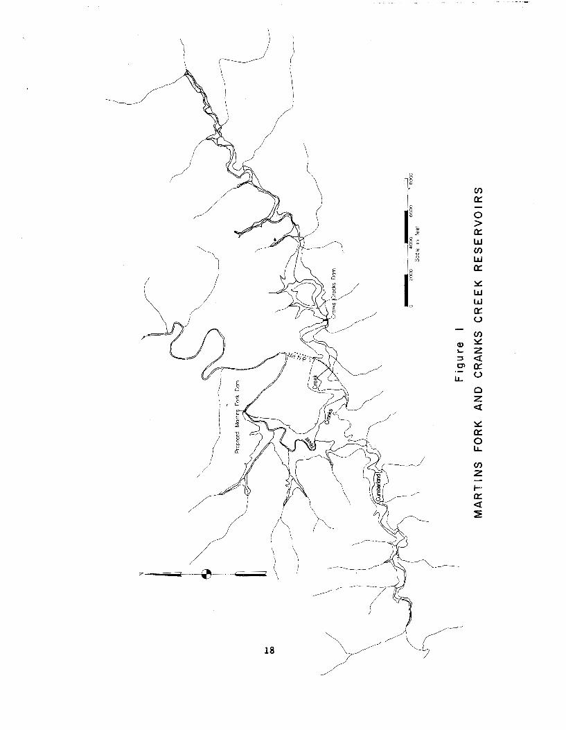
Reservoir o u t l i n e s of both t h e e x i s t i n g and proposed r e s e r v o i r s a r e
shown i n f i g u r e 1.
Figure 2 s h m s a p r o f i l e of the streambed from the s i te of the pro-
posed Martins Fork Dam up Martins Fork of t h e Cumberland River t o the
confluence with Cranks Creek and thence up Cranks Creek. Pe r t inen t
e l eva t ions a r e shown f o r each dam.
Also, f i g u r e 2 i l l u s t r a t e s a primary point of concern i n the study.
Cranks Creek Dam s tands some 85 f e e t h igher than the proposed Martins
Fork s t r u c t u r e and is located on1.y 3.9 m i l e s upstream. How much of
t h i s energy head would be d i s s ipa ted as the f lood wave t raveled t o
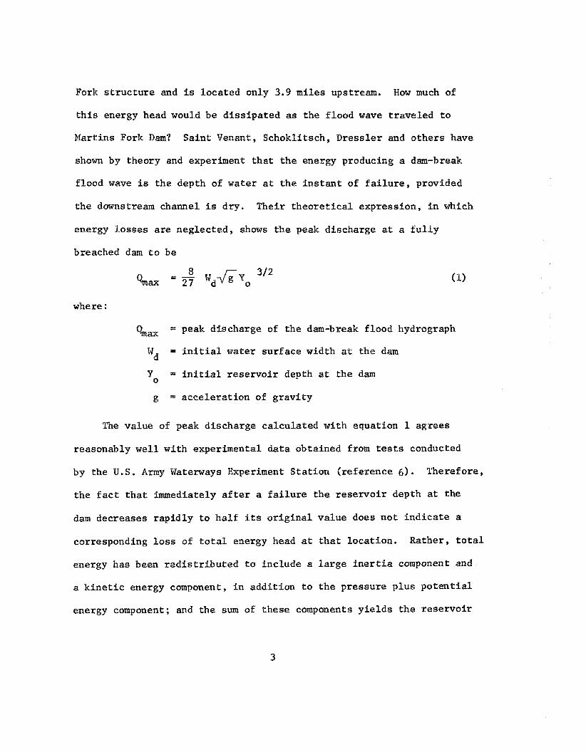
Martins Fork Dam? Sa in t Venant, Schokli tsch, Dress ler and o the r s have
shown by theory and experiment t h a t t h e energy producing a dam-break
f lood wave is t h e depth of water a t t h e i n s t a n t of f a i l u r e , provided
the downstream channel is dry. Their t h e o r e t i c a l expression, f n which
energy losses a r e neglected, shows t h e peak discharge a t a f u l l y
breached dam t o be
where :
a x = peak discharge of the dam-break f lood hydrograph
Wd = i n i t i a l water su r face width a t the dam
Y = i n i t i a l r e s e r v o i r depth a t the dam 0
g = acce le ra t ion of g rav i ty
The value of peak discharge ca lcula ted with equation 1 agrees
reasonably well with experimental da ta obtained from t e s t s conducted
by the U.S. Army Waterways Experiment S ta t ion ( reference 6). Therefore,
the f a c t t h a t immediately a f t e r a f a i l u r e t h e r e s e r v o i r depth a t the
dam decreases r ap id ly t o ha l f i ts o r i g i n a l va lue does n o t i n d i c a t e a
corresponding l o s s of t o t a l energy head a t t h a t locat ion . Rather, t o t a l
energy has been r e d i s t r i b u t e d t o include a l a r g e i n e r t i a component and
a k i n e t i c energy component, i n addi t ion t o t h e pressure p lus p o t e n t i a l
energy component; and the sum of these components y i e l d s the r e se rvo i r

elevat ion j u s t p r i o r t o f a i l u r e . The important energy l o s s e s occur a s
t h e f lood wave moves downstream and include f r i c t i o n losses , bend
losses , expansion and contrac t ion losses and others .
I n addi t ion t o energy considerat ions, the volume of water which
is ava i l ab le i n Cranks Creek Reservoir t o s u s t a i n the f lood wave must
be considered. Figure 3 shows the capacity of each rese rvo i r a s a
function of i ts elevation. The increase i n e leva t ion of Martins Fork
Reservoir due t o s t o r i n g the volume of water i n t h e flood wave could
possibly be g r e a t e r than the energy considerat ion. This would depend
on rate of energy d i s s ipa t ion and the r a t e of outflow from Martins
Fork. It is a l s o poss ib le t h a t the maximum force could r e s u l t from
some combination of the energy and volume considerat ions. Therefore,
a time h i s t o r y of t h e f lood wave motion is required t o adequately analyze
the problem.
Methods which a r e commonly used i n f lood rout ing, such a s t h e
modified Puls , Muskingum, Tatum, and straddle-stagger, permit d i r e c t
considerat ion of volumes only. I n d i r e c t l y , energy considerat ions a r e
in fe r red by c a l i b r a t i n g these methods t o some experienced event. Such
methods a r e inadequate f o r routing the dam-break flood--at l e a s t i n the
e a r l y s t ages , because energy plays such a dominant r o l e i n the movement.
Therefore, one must r e s o r t t o a so lu t ion of the b a s i c equations of
unsteady flow t o consider both cont inui ty and momentum.
A number of so lu t ion techniques have been advanced over t h e pas t
few years , but the method presented by Garrison, Granju and Pr ice
(reference 1) has been used i n t h i s study. It is , however, based on
a so lu t ion of t h e gradually var ied unsteady-flow equations through the
use of an e x p l i c i t f i n i t e d i f f e r e n c e scheme developed by Stoker. Terz id i s
and St re lkoff (reference 5) , i n s t u d i e s involving a hydraul ic bore,
demonstrated t h a t such a so lu t ion technique ca lcula ted t h e wave height
c o r r e c t l y , bu t f a i l e d t o maintain cont inui ty i n t h a t an excess water
volume was developed f o r the wave. The problem w a s corrected by accounting
f o r energy losses r e s u l t i n g from flow condit ions i n t h e wave f ron t . On
t h e o ther hand, Martin arid D e Fazio (reference 3) s tudied cases of r ap id ly
var ied flow involving an undular type of flood wave movement r a t h e r than
a bore type, and they found t h e so lu t ion developed by Stoker t o be
adequate f o r t h e i r design s tudies . Because of t h e depth of water down-
stream from Cranks Creek Dam, the f lood movement i n t h i s study was
expected t o be more l i k e the undular wave than a hydraulic bore. There-
fo re , Stoker 's so lu t ion technique was considered s a t i s f a c t o r y . However,
cont inui ty checks w e r e made t o insure a reasonable volume was being
maintained during the routing.
Numerous assumptions were necessary i n order t o rou te t h e dam-break
fl.ood. Generally, they can be divided i n t o two categor ies : (1) those
b a s i c t o es tab l i sh ing t h e problem and method f o r so lu t ion , and
(2) those necessary i n assigning values used i n the a c t u a l ca lcula t ions .
I n most cases, judgment w a s guided by the e f f o r t t o produce the most
c r i t i c a l s i t u a t i o n f o r Martins Fork Dam. The assumptions a r e l i s t e d
below:
a. The f a i l u r e of Cranks Creek Dam is instantaneous and
complete.
b. Pressure d i s t r i b u t i o n is hydros ta t i c a t each cross sec t ion.
c. Velocity d is t r ibut i .on is uniform over t h a t port ion of t h e
cross sec t ion conveying flow.
d. Steady flow n-values are applicable.
e. An e x i s t i n g r a i l r o a d crossing j u s t downstream from Cranks
Creek Dam is washed out upon impact of the f lood wave and t h e r e s u l t i n g
energy l o s s is negl ig ib le .
f . Energy l o s t a t t h e junction of Cranks Creek and Martins
Fork mainstem is negl ig ib le .
g. The e f f e c t of t r a n s i e n t waves on energy d i s s i p a t i o n , due
t o s inuos i ty of the channel, can be ignored.
h. Changes i n boundary geometry due t o scour and f i l l can
be neglected.
i. The model is v e r i f i e d when rese rvo i r volumes and t h e
spil lway design f lood outflow hydrograph matches d a t a obtained from
conventional routing techniques i n e a r l i e r s tudies . "

j. The overflow r a t i n g curve f o r Martins Fork Dam i s no t
a f fec ted by tai . lwater .
Pe r t inen t da ta f o r both p r o j e c t s a r e shown i n t a b l e 1.
Table 1, Bertfnent Data S s r Both P r o j e c t s
Location bv Stream Name
Cranks Creek Dam, Proposed Martins - Exis t ing - -- Fork Dam --
Cranks Creek Martins Fork of the Cumberland River
Miles above mouth 2.4 15.6
Drainage Area( (sq. m i . ) 24.8 55.7
T z of Dam Earth F i l l Concrete
Top of dam e leva t ion ( f e e t ) 1443 Streambed el.evati.on (approx,
f e e t ) 1323 Length of d a m ( f ee t ) 640
Spillway,
Crest e l eva t ion ( f e e t ) 1430 Crest length ( f ee t ) 200 Design f lood, peak-discharge
(c f s ) 2 5 100 Design f lood, peak-elevation
( f e e t ) 1441.5
Reservoir Capacity -- ---------
Normal summer operat ing pool, e l eva t ion ( f e e t ) 142 0 capaci ty (acre-feet) 6 400
Capacity a t spi l lway c r e s t , e l eva t ion (acre- f e e t ) 9000
Top of dam e leva t ion (acre-feet) 14000
Distance between the two p r o j e c t s (miles)
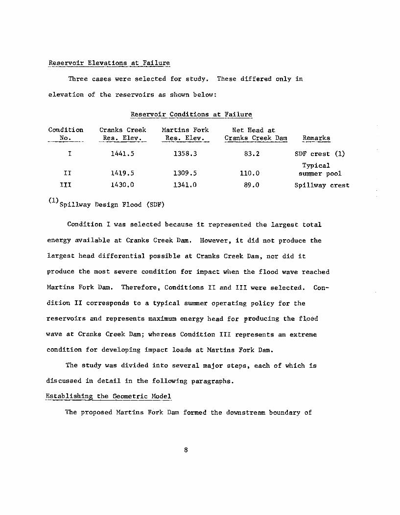
Reservoir Elevations a t Fa i lu re
Three cases were se lec ted f o r study. These d f f fe red only i n
e l eva t ion of t h e r e se rvo i r s a s shown below:
Reservoir Conditions a t F a i l u r e -
Condition Cranks Creek Martins Fork N e t Head a t No. - .--- - Res. Elev. -- Res. Elev. Cranks Creek Dam Remarks -- --
1 1441.5 1.358.3 83.2 SDF c r e s t (1)
Typical I1 1419.5 1309.5 110.0 summer pool
I11 1430.0 1341.0 89 .O Spillway c r e s t
'l) spi l lway Design Flood (SDF)
Condition I w a s se l ec ted because i t represented the l a r g e s t t o t a l
energy ava i l ab le a t Cranks Creek Dam. However, i t did no t produce the
l a r g e s t head d i f f e r e n t i a l poss ib le a t Cranks Creek Dam, nor did it
produce the most severe condit ion f o r impact when the f lood wave reached
Martins Fork Dam. Therefore, Conditions 11 and I11 were se lec ted . Con-
d i t i o n I1 corresponds t o a t y p i c a l s u m e r operat ing pol icy f o r the
r e s e r v o i r s and represents maximum energy head f o r producimg the flood
wave at Cranks Creek Dam; whereas Condition I11 represents an extreme
condit ion f o r developing impact loads a t Martins Fork Dam.
The s tudy was divided i n t o severa l major s t e p s , each of which is
discussed i n d e t a i l i n the following paragraphs.
Es tabl ish ing t h e e o m e t r i c Model - -- --
The proposed Martins Fork Dam formed t h e downstream boundary of
the model, and the upstream end of Cranks Creek Reservoir formed the
upstream boundary. Cross sec t ions were located t o def ine t o t a l volume
i n each rese rvo i r , and, where they extended up t r i b u t a r y arms, a r t i -
f i c i a l flow boundaries were imposed t o separa te t h a t por t ion of the
sec t ion which conveys flow from t h a t por t ion which only s t o r e s water.
From these sec t ions geometric da ta were ca lcula ted f o r nodal po in t s
spaced 1.82 ha l f m i l e a p a r t , thus forming the b a s i c geometric model f o r
the unsteady flow computer program.
Determining Hydraulic Roughness
Since f r i c t i o n l o s s was such an important considerat ion i n t h i s
s tudy, the s e l e c t i o n of r e a l i s t i c n-values f o r Manning's equation was
of primary importance. Values of 0.05 f o r the channel and 0.10 f o r the
overbanks had been used i n o ther s t u d i e s by engineers f ami l i a r with the
streams i n t h i s a rea . These values were, however, based on n a t u r a l
condit ions. Values of 0.03 and 0.01 had been used f o r r e s e r v o i r condit ions.
Since the flow v e l o c i t y associated with the dam-break f lood was expected
t o be more nea r ly t h a t f o r n a t u r a l condit ions than t h a t which would be
expected with the r e se rvo i r impounded, the n a t u r a l condit ions n-values
were used. These were adjus ted i n t o composite va lues f o r the e n t i r e
cross sec t ion and t o account f o r the s inuos i ty of the v a l l e y , which
r e s u l t e d i n a composite n-value of .07 f o r each c ross sec t ion . In Cranks
Creek t h i s value was reduced t o .05, s ince t h e flow condi t ions would tend
toward preimpoundment condit ions a s the water drained out .

Verifying the D i g i t a l Model we+
Before rout ing the dam-break f lood, the Spillway Design Flood f o r
Martins Fork w a s routed through both reservoi rs . The r e s u 1 . t ~ compared
favorably wi th those from e a r l i e r s t u d i e s i n which conventional rout ing
techniques were used. Also, water su r face p r o f i l e s were ca lcu la ted f o r
the peak discharge of the spi l lway design flood. These p r o f i l e s were
compared with p r o f i l e s ca lcula ted using a s teady flow, backwater computer
program. The comparisons from these t e s t s were considered s u f f i c i e n t
t o v e r i f y the model f o r the proposed study.
Es tabl ish ing Boundary Conditions and I n i t i a l Conditions - ---.-
A discharge r a t i n g curve was used f o r the dormstream boundary
condit ion a t Martins Fork Dam. It included flow over the top of the
dam, a s we l l a s through the spi l lway.
The Spl.llway Design Flood discharge hydrograph was used a t the
upstream boundary i n Condition I. In t h e o ther two cases , inflow
was assumed t o be zero.
Local a r e a inflow entered the model a t the confluence of Cranks
Creek and Martins Fork mainstem. No other l o c a l inflow po in t s were
es tabl i shed.
For al.1 t h r e e condit ions of f a i l u r e , Cranks Creek Dam was considered
a s a f i n i t e d i scon t inu i ty i n the i n i t i a l water surface p r o f i l e . Using
t h i s approach, a s apposed t o t r e a t i n g i t a s an end boundary, t h e increase
i n t a i l w a t e r e l eva t ion accompanying the dam-break f lood wave could
be included i n ca lcu la t ions f o r the discharge hydrograph a t the dam axis.
Routing the Dam-Break Flood f o r Condition I - - -- --
The r e s u l t s of routing the dam-break f lood f o r Condition 1 a r e
shown i n f i g u r e 4 i n the form of discharge and e leva t ion hydrographs
a t Cranks Creek Dam a x i s and a t Martins Fork Dam axis .
The impact of t h e f lood wave on Martins Fork Dam r e su l t ed i n a
28-foot inc rease i n water su r face e l eva t ion above the SDF peak, a s
the i n e r t i a and k i n e t i c energy components were transformed back i n t o
a pressure energy. The peak discharge a t Martins Fork was 190,000 c i s .
Four minutes were required f o r the wave t o t r a v e l from Cranks Creek Dam
t o Martins Fork Dam.
Two a l t e r n a t i v e methods f o r computing t r a v e l time, a wave c e l e r i t y
computation based on i n i t i a l depth and a forward c h a r a c t e r i s t i c computa-
t i o n based on c e r l e r i t y p lus flow ve loc i ty , produced t r a v e l times of
6 minutes and 5.5 minutes, respect ive ly . The t r a v e l t i m e ca lcu la ted by
the rout ing method used i n the study appears t o be reasonable, based
upon comparison wi th these values.
The peak outflow from Cranks Creek Reservoir, curve one of f i g u r e 4 ,
is 1,400,000 c i s . The value obtained by applying equation 1, 1,200,000 c i s ,
compares favorably with t h i s peak outflow.
The peak discharge is important because i t inf luences t h e r a t e of
energy d i s s i p a t i o n due t o f r i c t i o n . This point was i l l u s t r a t e d i n the
study by f i r s t including a l l s to rage volume on Martins Fork mainstem,
upstream from Cranks Creek, then reca lcu la t ing the rout ing wi th t h a t
volume excluded. The peak energy a t Martins Fork Dam was 4 f e e t higher
i n t h e f i r s t case because the add i t iona l s torage volume reduced the
peak discharge and, consequently, the r a t e f r i c t i o n loss .
The r e s u l t s of a s e n s i t i v i t y study i n which the composite n-values
were var ied is shown i n f igure 5. For Condition I f a i l u r e , n-values
of .05,.07 and .10 were assigned and the f lood wave ca lcula ted and
routed t o Martins Fork Dam. The r e s u l t s show t h a t t o t a l energy remain-
ing i n the f lood wave when i t reaches Martins Fork Dam is highly dependent
upon the hydraulic roughness value. The determination of these values
should, the re fo re , receive a g r e a t dea l of considerat ion i n planning a
rout ing study.
Routing the Dam-Break Flood f o r Condition I1 --- -" --.
The flood t h a t would r e s u l t from a f a i l u r e when both rese rvo i r s
a r e a t normal, summer operat ing pools (Condition 11) is represented
i n f i g u r e 6. Under t h i s condit ion, the e n t i r e contents of Cranks Creek
Reservoir would be s to red i n Martins Fork Reservoir and maximum pool.
e levat ion would be we l l below t h e spillway c r e s t , even including t h e
impact of the f lood wave.
This condition was used t o test f o r cont inui ty by ca lcu la t ing t h e
volume under the hydrograph a t Cranks Creek Dam and comparing the r e s u l t
with t h e elevation-storage curve of f igure 3. The comparison indicated
t h a t the volumes were within 15 percent of one another, wi th the rout ing
method tending t o produce an excess of water. This conformed with the
experience reported by Terzidas and S t re lkof f . The discrepancy i n
con t inu i ty was no t considered t o be unreasonable when evaluated wi th
r e spec t t o the u n c e r t a i n t i e s associa ted wi th o t h e r aspects of the
study.
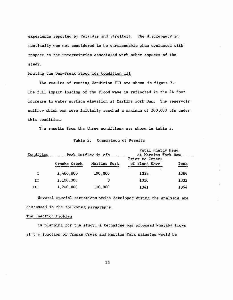
Routing t h e Dam-Break Flood f o r Condition I11 ---------
The r e s u l t s of rout ing Condition I11 a r e shown 5n f i g u r e 7,
The f u l l impact loading of the f lood wave is r e f l e c t e d In the 24-foot
increase i n water surface e l eva t ion a t Martins Fork Dam. The rese rvo i r
outflow which w a s zero i n i t i a l l y reached a maximum of 100,000 c f s under
t h i s condition.
The r e s u l t s from the t h r e e condi t ions are shown i n t a b l e 2.
Table 2. Comparison of Resu1.t~
To ta l Energy Head Condition - -.- Peak Outflow i n c f s -, a t Har t ins Fork Dam
P r i o r t o Impact Cranks Creek Martins Fork ---- --"." --- of Flood Wave -- Peak --
Several s p e c i a l s i t u a t i o n s which developed during the ana lys i s a r e
discussed i n t h e following paragraphs.
The Junction Problem
In planning f o r the study, a technique was proposed whereby flows
a t the junction of Cranks Creek and Martins Fork mainstem would be

determined by successive approximations using two routing models.
Br ie f ly , t h i s technique was t o be the following: The primary model
w ~ u l d extend through Cranks Creek Reservoir t o Martins Fork Dam. Tire
secondary model would extend from the upstream end of the Martins Fork
arm down t o the confluence with Cranks Creek. The f i r s t rout ing
would be made with t h e primary model, and would assume zero inflow from
the Martins Fork mafnstem. The second s t e p would u t l i z e e levat ions
ca lcula ted f o r t h e junction i n t h e f i . r s t s t e p and route down t h e
Martins Fork arm of the rese rvo i r t o determine the discharge enter ing
t h e junction. Step 1 would be repeated. This a l t e r n a t i n g between the
primary and secondary rout ing models would continue u n t i l the same
junction e levat ions and discharges r e s u l t e d i n two successive s teps .
Such P ' c o n v e r g e n c e ' ~ o u l d i n d i c a t e t h a t a so lu t ion had been reached.
This technique proved t o be unsuccessful. The changes i n discharge
and e levat ion were s o rapid t h a t convergence of r e s u l t s from t h e two
models could not be achieved. Fortunately, t h e peak of the f lood
wave required only a minute t o t r a v e l from the confl.uence t o the dam.
During t h i s t i m e , t he wave would t r a v e l only a shor t d is tance up Martins
Fork mainstem. Therefore, t h a t wave t r a v e l d is tance could be neglected
and the spil lway design f lood hydrograph could be entered a s l o c a l
inflow.
C r i t i c a l Depth Controls - -
A sudden f a i l u r e of a dam r e s u l t s i n a negative wave which t r a v e l s

up the rese rvo i r while the pos i t ive wave is being produced downstream
from the dam. The geometry of Cranks Creek Reservoir caused a c r i t i c a l
depth con t ro l t o form near r i v e r m i l e 4 which r e s t r i c t e d t h i s negative
wave from developing upstream from t h a t point during Condition T I . For-
tunate ly , the amount of s torage capacity upstream from m i l e 4 was small
and could be neglected because the computer program did not perform
s a t i s f a c t o r i l y f o r supercri t i .ca1 flow. Therefore, t h e upstream boundary
was s h i f t e d down t o m i l e 4 i n the rout ing model and the ca lcu la t ions
continued with no se r ious e r r o r r e s u l t i n g from t h i s s impl i f ica t ion.
Dry Channel a t the Upstream Boundary
I n Conditions I and 111, t h e r e w a s s u f f i c i e n t i n i t i a l depth so
the negative wave could pass upstream from mile 4 without developing
t r a n s i t i o n s between s u p e r c r i t i c a l and s u b c r i t i c a l flow. However,
a s s t rong negative waves would approach the upstream boundary, the
water depth would temporarily go t o zero which, again, caused t h e
computer program t o malfunction. Attempts t o e l iminate t h i s problem
by specifying a minimum s tage a t the upstream boundary caused other
i n s t a b i l i t i e s even though 1-second computation i n t e r v a l s were employed.
Therefore, rout ings were terminated. In a91 cases, t h e peak flow had
passed Martins Fork Dam before routings terminated.
I n i t i a l Depth i n the Channel . -
I n a l l th ree cases s tudied, t h e r e was a s u b s t a n t i a l depth of water
downstream from Cranks Creek Dam. Otherwise, a hydraulic bore would

have formed and a d i f f e r e n t formulation of t h e routing equations
would have ben required. (This depth contributed t o movement of
the f lood wave, r e su l t ing i n l a r g e r wave v e l o c i t i e s than would have
been experienced i n a dry channel.)
Any one of these spec ia l condit ions could render a study
impossible with t h i s model i f i ts inf luenee predominated, It fs
believed t h a t i.n t h i s study they were t rea ted i n a conservative manere.
A genera l ly appl icable so lu t ion technique which could be used regard less
of whether the channel is w e t o r dry, junctions with t r i b u t a r i e s a r e
present or n o t , o r the flow changes between s u b c r i t i c a l and s u p e r c r i t i c a l
condit ions is not present ly avai lable . Since 1968 The Hydrologic
Engineering Center has been working, through contracted research, t o
0btai.n such a solut ion? and progress i s being made; but the complete
so lu t ion of the general case i s s t i l l i n the fu tu re .
SUMMARY AND CONCLUSIONS
The object ive of t h i s study w a s t o develop a reasonable method
f o r ca lcu la t ing energy remaining i n the flood wave a t Martins Fork Dam
and f o r converting t h e i n e r t i a and k i n e t i c energies i n t o total . energy
from which pressure loadings could be determined. The body of theory
appears t o be reasonably w e l l e s t ab l i shed , b u t methods f o r i.mplementing
t h i s theory require numerical techniques which u t i l i z e the e l e c t r o n i c
computer, and a complete so lu t ion of t h e general case is no t present ly
avai lable . Some progress is being made toward such a solut ion; however,

in the meantime, studies of dam-break floods w i l l be required, and
these studi.es w i l l have to be limited i n scope because of limitations
in available methods. A great deal of engi.neerl.ng judgment w i l l be
required to simplify and approximate the actual, probl.em so the existing
methods can b e employed,
Fig
ure
I
MA
RT
INS
F
OR
K
AN
D
CR
AN
KS
C
RE
EK
R
ES
ER
VO
IRS


Elevation of Martins Fork Reservoir
Elevation of Cranks Creek Reservoir

Figure
PEAK
4. RESULTS F R O M FAILURE AT
O F S. D. F. ( CONDITION 1)
2 1.


F igure 6 . F A I L U R E W i T H B O T H R E S E R V O I R S AT
SUMMER P O O L E L E V A T I O N ( C O N D I T I O N a) 23
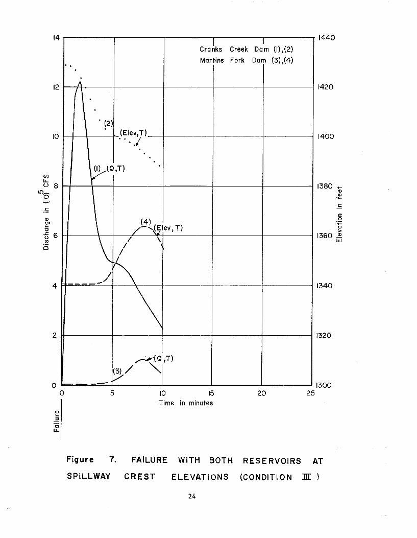
Figure 7. FAILURE WITH BOTH R E S E R V O ! R S A T
SPILLWAY CREST ELEVATIONS (CONDITION IK
0 5 10 15 20 2 5
2 7 - .- 0 LL
Time in minutes

REFERENCES
1. Garr ison, Jack M., Jean-Pierre P. Granju, and James T. P r i c e , ." .Unsteady Flow Simulat ion i n Rivers and Reservoi rs , " J o u r n a l
of t h e Hydraul ics Div is ion , ASCE, Vol. 95, No. HY5, September 1969.
2. Hendez-sari, F. ) f . , Open-Charinel F l m , The Mam~illan Company, Mew York, pp. 304-312, 1966.
3. Nar t in , C . , Samuel and Frank G , De Fazio, "Open-Channel Surge Sfmulition by D i g i t a l Computer," J o u r n a l sf t h e Hydraul ics Div is ion , ASCE, Vol. 95, No. NY6, November 1969.
4. S t r e l k o f f , . . Theodor, "One-Dimensional Equations of Open-Channel Flow," Jou rna l of t h e Hydraul ics Div is ion , ASCE, Vol. 95, No. HY3, May 1.969.
5. T e r z i d i s , George and Theodor S t r e l k o f f , "Computation of Open-Channel Surges and Shocks," Jou rna l of t h e Hydraul ics Div is ion , ASCE, Vol. 96, No. HY12, December 1970.
6 . U.S. Army Corps of Engineers , Waterways Experiment s ta t ion$ , Vicks- burg, Mis s i s s ipp i , Floods P,esulti.ng from Suddenly Breached D a m s , Conditions of plinimun Res is tance , '' Repcrt No. 1, 1960.


Technical Paper Series TP-1 Use of Interrelated Records to Simulate Streamflow TP-2 Optimization Techniques for Hydrologic
Engineering TP-3 Methods of Determination of Safe Yield and
Compensation Water from Storage Reservoirs TP-4 Functional Evaluation of a Water Resources System TP-5 Streamflow Synthesis for Ungaged Rivers TP-6 Simulation of Daily Streamflow TP-7 Pilot Study for Storage Requirements for Low Flow
Augmentation TP-8 Worth of Streamflow Data for Project Design - A
Pilot Study TP-9 Economic Evaluation of Reservoir System
Accomplishments TP-10 Hydrologic Simulation in Water-Yield Analysis TP-11 Survey of Programs for Water Surface Profiles TP-12 Hypothetical Flood Computation for a Stream
System TP-13 Maximum Utilization of Scarce Data in Hydrologic
Design TP-14 Techniques for Evaluating Long-Tem Reservoir
Yields TP-15 Hydrostatistics - Principles of Application TP-16 A Hydrologic Water Resource System Modeling
Techniques TP-17 Hydrologic Engineering Techniques for Regional
Water Resources Planning TP-18 Estimating Monthly Streamflows Within a Region TP-19 Suspended Sediment Discharge in Streams TP-20 Computer Determination of Flow Through Bridges TP-21 An Approach to Reservoir Temperature Analysis TP-22 A Finite Difference Methods of Analyzing Liquid
Flow in Variably Saturated Porous Media TP-23 Uses of Simulation in River Basin Planning TP-24 Hydroelectric Power Analysis in Reservoir Systems TP-25 Status of Water Resource System Analysis TP-26 System Relationships for Panama Canal Water
Supply TP-27 System Analysis of the Panama Canal Water
Supply TP-28 Digital Simulation of an Existing Water Resources
System TP-29 Computer Application in Continuing Education TP-30 Drought Severity and Water Supply Dependability TP-31 Development of System Operation Rules for an
Existing System by Simulation TP-32 Alternative Approaches to Water Resources System
Simulation TP-33 System Simulation of Integrated Use of
Hydroelectric and Thermal Power Generation TP-34 Optimizing flood Control Allocation for a
Multipurpose Reservoir TP-35 Computer Models for Rainfall-Runoff and River
Hydraulic Analysis TP-36 Evaluation of Drought Effects at Lake Atitlan TP-37 Downstream Effects of the Levee Overtopping at
Wilkes-Barre, PA, During Tropical Storm Agnes TP-38 Water Quality Evaluation of Aquatic Systems
TP-39 A Method for Analyzing Effects of Dam Failures in Design Studies
TP-40 Storm Drainage and Urban Region Flood Control Planning
TP-41 HEC-5C, A Simulation Model for System Formulation and Evaluation
TP-42 Optimal Sizing of Urban Flood Control Systems TP-43 Hydrologic and Economic Simulation of Flood
Control Aspects of Water Resources Systems TP-44 Sizing Flood Control Reservoir Systems by System
Analysis TP-45 Techniques for Real-Time Operation of Flood
Control Reservoirs in the Merrimack River Basin TP-46 Spatial Data Analysis of Nonstructural Measures TP-47 Comprehensive Flood Plain Studies Using Spatial
Data Management Techniques TP-48 Direct Runoff Hydrograph Parameters Versus
Urbanization TP-49 Experience of HEC in Disseminating Information
on Hydrological Models TP-50 Effects of Dam Removal: An Approach to
Sedimentation TP-51 Design of Flood Control Improvements by Systems
Analysis: A Case Study TP-52 Potential Use of Digital Computer Ground Water
Models TP-53 Development of Generalized Free Surface Flow
Models Using Finite Element Techniques TP-54 Adjustment of Peak Discharge Rates for
Urbanization TP-55 The Development and Servicing of Spatial Data
Management Techniques in the Corps of Engineers TP-56 Experiences of the Hydrologic Engineering Center
in Maintaining Widely Used Hydrologic and Water Resource Computer Models
TP-57 Flood Damage Assessments Using Spatial Data Management Techniques
TP-58 A Model for Evaluating Runoff-Quality in Metropolitan Master Planning
TP-59 Testing of Several Runoff Models on an Urban Watershed
TP-60 Operational Simulation of a Reservoir System with Pumped Storage
TP-61 Technical Factors in Small Hydropower Planning TP-62 Flood Hydrograph and Peak Flow Frequency
Analysis TP-63 HEC Contribution to Reservoir System Operation TP-64 Determining Peak-Discharge Frequencies in an
Urbanizing Watershed: A Case Study TP-65 Feasibility Analysis in Small Hydropower Planning TP-66 Reservoir Storage Determination by Computer
Simulation of Flood Control and Conservation Systems
TP-67 Hydrologic Land Use Classification Using LANDSAT
TP-68 Interactive Nonstructural Flood-Control Planning TP-69 Critical Water Surface by Minimum Specific
Energy Using the Parabolic Method

TP-70 Corps of Engineers Experience with Automatic Calibration of a Precipitation-Runoff Model
TP-71 Determination of Land Use from Satellite Imagery for Input to Hydrologic Models
TP-72 Application of the Finite Element Method to Vertically Stratified Hydrodynamic Flow and Water Quality
TP-73 Flood Mitigation Planning Using HEC-SAM TP-74 Hydrographs by Single Linear Reservoir Model TP-75 HEC Activities in Reservoir Analysis TP-76 Institutional Support of Water Resource Models TP-77 Investigation of Soil Conservation Service Urban
Hydrology Techniques TP-78 Potential for Increasing the Output of Existing
Hydroelectric Plants TP-79 Potential Energy and Capacity Gains from Flood
Control Storage Reallocation at Existing U.S. Hydropower Reservoirs
TP-80 Use of Non-Sequential Techniques in the Analysis of Power Potential at Storage Projects
TP-81 Data Management Systems of Water Resources Planning
TP-82 The New HEC-1 Flood Hydrograph Package TP-83 River and Reservoir Systems Water Quality
Modeling Capability TP-84 Generalized Real-Time Flood Control System
Model TP-85 Operation Policy Analysis: Sam Rayburn
Reservoir TP-86 Training the Practitioner: The Hydrologic
Engineering Center Program TP-87 Documentation Needs for Water Resources Models TP-88 Reservoir System Regulation for Water Quality
Control TP-89 A Software System to Aid in Making Real-Time
Water Control Decisions TP-90 Calibration, Verification and Application of a Two-
Dimensional Flow Model TP-91 HEC Software Development and Support TP-92 Hydrologic Engineering Center Planning Models TP-93 Flood Routing Through a Flat, Complex Flood
Plain Using a One-Dimensional Unsteady Flow Computer Program
TP-94 Dredged-Material Disposal Management Model TP-95 Infiltration and Soil Moisture Redistribution in
HEC-1 TP-96 The Hydrologic Engineering Center Experience in
Nonstructural Planning TP-97 Prediction of the Effects of a Flood Control Project
on a Meandering Stream TP-98 Evolution in Computer Programs Causes Evolution
in Training Needs: The Hydrologic Engineering Center Experience
TP-99 Reservoir System Analysis for Water Quality TP-100 Probable Maximum Flood Estimation - Eastern
United States TP-101 Use of Computer Program HEC-5 for Water Supply
Analysis TP-102 Role of Calibration in the Application of HEC-6 TP-103 Engineering and Economic Considerations in
Formulating TP-104 Modeling Water Resources Systems for Water
Quality
TP-105 Use of a Two-Dimensional Flow Model to Quantify Aquatic Habitat
TP-106 Flood-Runoff Forecasting with HEC-1F TP-107 Dredged-Material Disposal System Capacity
Expansion TP-108 Role of Small Computers in Two-Dimensional
Flow Modeling TP-109 One-Dimensional Model for Mud Flows TP-110 Subdivision Froude Number TP-111 HEC-5Q: System Water Quality Modeling TP-112 New Developments in HEC Programs for Flood
Control TP-113 Modeling and Managing Water Resource Systems
for Water Quality TP-114 Accuracy of Computer Water Surface Profiles -
Executive Summary TP-115 Application of Spatial-Data Management
Techniques in Corps Planning TP-116 The HEC's Activities in Watershed Modeling TP-117 HEC-1 and HEC-2 Applications on the
Microcomputer TP-118 Real-Time Snow Simulation Model for the
Monongahela River Basin TP-119 Multi-Purpose, Multi-Reservoir Simulation on a PC TP-120 Technology Transfer of Corps' Hydrologic Models TP-121 Development, Calibration and Application of
Runoff Forecasting Models for the Allegheny River Basin
TP-122 The Estimation of Rainfall for Flood Forecasting Using Radar and Rain Gage Data
TP-123 Developing and Managing a Comprehensive Reservoir Analysis Model
TP-124 Review of U.S. Army corps of Engineering Involvement With Alluvial Fan Flooding Problems
TP-125 An Integrated Software Package for Flood Damage Analysis
TP-126 The Value and Depreciation of Existing Facilities: The Case of Reservoirs
TP-127 Floodplain-Management Plan Enumeration TP-128 Two-Dimensional Floodplain Modeling TP-129 Status and New Capabilities of Computer Program
HEC-6: "Scour and Deposition in Rivers and Reservoirs"
TP-130 Estimating Sediment Delivery and Yield on Alluvial Fans
TP-131 Hydrologic Aspects of Flood Warning - Preparedness Programs
TP-132 Twenty-five Years of Developing, Distributing, and Supporting Hydrologic Engineering Computer Programs
TP-133 Predicting Deposition Patterns in Small Basins TP-134 Annual Extreme Lake Elevations by Total
Probability Theorem TP-135 A Muskingum-Cunge Channel Flow Routing
Method for Drainage Networks TP-136 Prescriptive Reservoir System Analysis Model -
Missouri River System Application TP-137 A Generalized Simulation Model for Reservoir
System Analysis TP-138 The HEC NexGen Software Development Project TP-139 Issues for Applications Developers TP-140 HEC-2 Water Surface Profiles Program TP-141 HEC Models for Urban Hydrologic Analysis

TP-142 Systems Analysis Applications at the Hydrologic Engineering Center
TP-143 Runoff Prediction Uncertainty for Ungauged Agricultural Watersheds
TP-144 Review of GIS Applications in Hydrologic Modeling
TP-145 Application of Rainfall-Runoff Simulation for Flood Forecasting
TP-146 Application of the HEC Prescriptive Reservoir Model in the Columbia River Systems
TP-147 HEC River Analysis System (HEC-RAS) TP-148 HEC-6: Reservoir Sediment Control Applications TP-149 The Hydrologic Modeling System (HEC-HMS):
Design and Development Issues TP-150 The HEC Hydrologic Modeling System TP-151 Bridge Hydraulic Analysis with HEC-RAS TP-152 Use of Land Surface Erosion Techniques with
Stream Channel Sediment Models
TP-153 Risk-Based Analysis for Corps Flood Project Studies - A Status Report
TP-154 Modeling Water-Resource Systems for Water Quality Management
TP-155 Runoff simulation Using Radar Rainfall Data TP-156 Status of HEC Next Generation Software
Development TP-157 Unsteady Flow Model for Forecasting Missouri and
Mississippi Rivers TP-158 Corps Water Management System (CWMS) TP-159 Some History and Hydrology of the Panama Canal TP-160 Application of Risk-Based Analysis to Planning
Reservoir and Levee Flood Damage Reduction Systems
TP-161 Corps Water Management System - Capabilities and Implementation Status