A Metallic Patch Antenna Using a Simple Short Probe for ...
6
A Metallic Patch Antenna Using a Simple Short Probe for Improving Impedance Match Bandwidth Ziyang Wang 1,2 , Zhao Yang 1 , and Yingzeng Yin 1 1 National Key Laboratory of Antennas and Microwave Technology Xidian University, Xi’an, Shaanxi 710071, People’s Republic of China [email protected], [email protected] 2 State Key Laboratory on Microwave and Digital Communications Tsinghua National Laboratory for Information Science and Technology Department of Electronic Engineering, Tsinghua University, Beijing, 100084, China [email protected], [email protected] Abstract ─ A metallic patch antenna using double-tuned impedance matching is presented in this paper. The antenna mainly consists of a rectangular ground plane, a radiation patch with U-slot and two short metal cylinders, with a size of 200mm×200mm×25.5mm. The two metal cylinders are used to connect the patch and the ground. With the common effects of the U-slot and the two metal cylinders, the impedance match has become better than before. Moreover, high harmonics and cross polarization are suppressed after loading two short pins. Measured results show that the antenna has a wide impedance bandwidth from 830 MHz to 970 MHz (16%) for voltage standing wave ratio (VSWR) less than 1.5, and a high gain level about 9.3dBi in a wide band. A good agreement is achieved between simulated and measured results. Therefore, the proposed metal antenna is a good choice for UHF RFID applications. Index Terms ─ Cross polarization, high harmonics, short probe, UHF RFID applications, wideband. I. INTRODUCTION Broadband antenna with a small size is a hot topic for antenna designers and it is a pair of contradictory unity of opposites. As we all know, a traditional antenna has a narrow band since only one resonance has been used [1]. An effective approach to add a new resonance point has been adopted to improve the bandwidth. Firstly, a ring slot has been reported in paper [2], while the radiation pattern is not very good. Another capacitive coupled technology is presented to enhance the bandwidth in paper [3], but the gains are not satisfactory results. U- slot and other capacitive gaps have been used to enhance the bandwidth in papers [4-5]. A parasitic element is also used to increase the bandwidth in [6-7], while there are a few reports about improving the impedance match. Other broadband antennas [11-12] are also presented. In this paper, a U-slot has been used to improve the bandwidth. After that, two metal cylinders are placed on the ends of the feeder symmetrically to improve the impedance match. Furthermore, the cross polarization and high order modes are also improved. The proposed antenna has a perfect impedance match bandwidth covering from 830MHz to 970MHz with desirable gains. It can be used for UHF RFID applications. Detailed design processes and test results are presented in the following chapters. II. ANTENNA DESIGN AND ANALYSIS Geometry for the proposed antenna and detailed design process will be presented in this section. A. Geometry of the proposed antenna Figure 1 shows the geometry and dimensions for the proposed antenna. The all-metal antenna is made of aluminum material. Air substrate is used to separate the ground with the radiation patch, which can improve the bandwidth. A single-probe is adopted as feeding structure installed at the center of radiation patch. Then, the bandwidth has improved by using a U-slot. Moreover, a good impedance match performance in a wide operating bandwidth is achieved by two metal cylinders. The antenna can be fixed by four dielectric cylinders. A prototype of the antenna is illustrated in Fig. 1, and the optimized parameters are as follows: W=200mm, L=200mm, W1=9mm, W2=8mm, W3=36mm, Wr=70mm, L1=126mm, L2=77mm, Lr=8mm, H=25mm, h1=1.5mm, h2=2mm. B. Theoretical analysis In this paper, multistage matching technology is used for broadening the bandwidth of antenna. In equation (1), the impedance matching equation is presented for guiding the design of broadband antenna ACES JOURNAL, Vol. 34, No. 1, January 2019 Submitted On: August 26, 2017 Accepted On: December 25, 2018 1054-4887 © ACES 115
Transcript of A Metallic Patch Antenna Using a Simple Short Probe for ...

A Metallic Patch Antenna Using a Simple Short Probe for Improving
Impedance Match Bandwidth
Ziyang Wang 1,2, Zhao Yang 1, and Yingzeng Yin 1
1 National Key Laboratory of Antennas and Microwave Technology
Xidian University, Xi’an, Shaanxi 710071, People’s Republic of China
[email protected], [email protected]
2 State Key Laboratory on Microwave and Digital Communications
Tsinghua National Laboratory for Information Science and Technology
Department of Electronic Engineering, Tsinghua University, Beijing, 100084, China
[email protected], [email protected]
Abstract ─ A metallic patch antenna using double-tuned
impedance matching is presented in this paper. The
antenna mainly consists of a rectangular ground plane, a
radiation patch with U-slot and two short metal cylinders,
with a size of 200mm×200mm×25.5mm. The two metal
cylinders are used to connect the patch and the ground.
With the common effects of the U-slot and the two metal
cylinders, the impedance match has become better than
before. Moreover, high harmonics and cross polarization
are suppressed after loading two short pins. Measured
results show that the antenna has a wide impedance
bandwidth from 830 MHz to 970 MHz (16%) for voltage
standing wave ratio (VSWR) less than 1.5, and a high
gain level about 9.3dBi in a wide band. A good
agreement is achieved between simulated and measured
results. Therefore, the proposed metal antenna is a good
choice for UHF RFID applications.
Index Terms ─ Cross polarization, high harmonics,
short probe, UHF RFID applications, wideband.
I. INTRODUCTION Broadband antenna with a small size is a hot topic
for antenna designers and it is a pair of contradictory
unity of opposites. As we all know, a traditional antenna
has a narrow band since only one resonance has been
used [1]. An effective approach to add a new resonance
point has been adopted to improve the bandwidth.
Firstly, a ring slot has been reported in paper [2], while
the radiation pattern is not very good. Another capacitive
coupled technology is presented to enhance the bandwidth
in paper [3], but the gains are not satisfactory results. U-
slot and other capacitive gaps have been used to enhance
the bandwidth in papers [4-5]. A parasitic element is also
used to increase the bandwidth in [6-7], while there are a
few reports about improving the impedance match. Other
broadband antennas [11-12] are also presented.
In this paper, a U-slot has been used to improve the
bandwidth. After that, two metal cylinders are placed on
the ends of the feeder symmetrically to improve the
impedance match. Furthermore, the cross polarization
and high order modes are also improved. The proposed
antenna has a perfect impedance match bandwidth
covering from 830MHz to 970MHz with desirable gains.
It can be used for UHF RFID applications. Detailed
design processes and test results are presented in the
following chapters.
II. ANTENNA DESIGN AND ANALYSIS Geometry for the proposed antenna and detailed
design process will be presented in this section.
A. Geometry of the proposed antenna
Figure 1 shows the geometry and dimensions for
the proposed antenna. The all-metal antenna is made of
aluminum material. Air substrate is used to separate the
ground with the radiation patch, which can improve
the bandwidth. A single-probe is adopted as feeding
structure installed at the center of radiation patch. Then,
the bandwidth has improved by using a U-slot. Moreover,
a good impedance match performance in a wide operating
bandwidth is achieved by two metal cylinders. The
antenna can be fixed by four dielectric cylinders. A
prototype of the antenna is illustrated in Fig. 1, and
the optimized parameters are as follows: W=200mm,
L=200mm, W1=9mm, W2=8mm, W3=36mm, Wr=70mm,
L1=126mm, L2=77mm, Lr=8mm, H=25mm, h1=1.5mm,
h2=2mm.
B. Theoretical analysis In this paper, multistage matching technology is
used for broadening the bandwidth of antenna. In
equation (1), the impedance matching equation is
presented for guiding the design of broadband antenna
ACES JOURNAL, Vol. 34, No. 1, January 2019
Submitted On: August 26, 2017 Accepted On: December 25, 2018 1054-4887 © ACES
115
where n is the tuned stage, and 𝐵𝑛 is the optimal
impedance bandwidth at the corresponding state. As we
know, a single radiation patch antenna can be considered
as a first-order resonant circuit as shown in Fig. 2 (a).
Corresponding to the impedance equation, the value of
n is equal to 1. The optimal bandwidth about 𝐵1 is
presented in equation (2). Furthermore, an optimal first-
order resonant mode can be obtained by tuning the
parameter of the antenna. In addition, the bandwidth for
mid-band and edge-band are demonstrated in equations
(4) and (5):
1 1
1 1( ) .
11sinh( ln( )) ln( )
n
nN
n n
BbQ
ba a
(1)
While 1,n 1,na 1,nb the bandwidth is shown
as following:
1
1 1,
1 1ln( ) ln( )
1
BVSWRQ Q
VSWR
(2)
0 ,L
QR
(3)
2
12
1 2 1 1,
1MB
VSWRB
Q Q VSWR
(4)
2
1 2
1 2 1 1.
2*1EB
VSWRB
Q Q VSWR
(5)
Fig. 1. Geometry of the proposed antenna.
The relationship about reflection coefficients, phase
and bandwidth about the double-tuned matching are
shown in the following equations (6), (7), (8):
1
tan( ),EBBQ
(6)
1 2tan( ),EB
(7)
2
2 1 , (8)
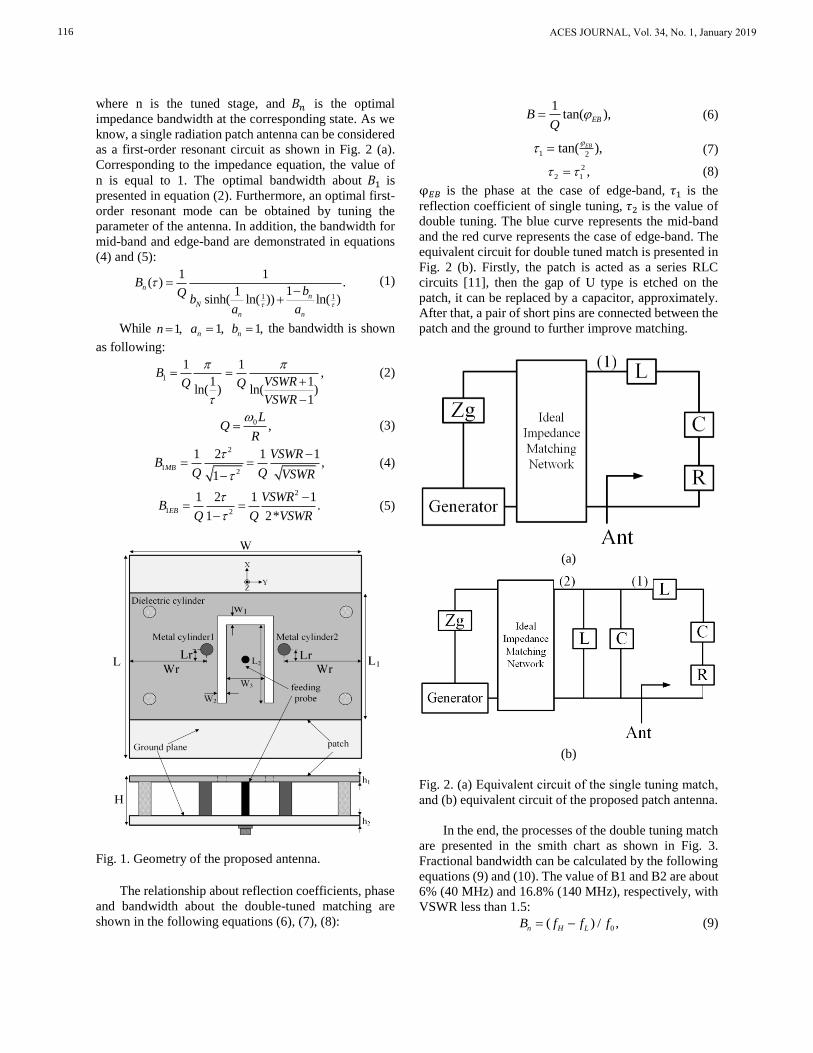
φ𝐸𝐵 is the phase at the case of edge-band, 𝜏1 is the
reflection coefficient of single tuning, 𝜏2 is the value of
double tuning. The blue curve represents the mid-band
and the red curve represents the case of edge-band. The
equivalent circuit for double tuned match is presented in
Fig. 2 (b). Firstly, the patch is acted as a series RLC
circuits [11], then the gap of U type is etched on the
patch, it can be replaced by a capacitor, approximately.
After that, a pair of short pins are connected between the
patch and the ground to further improve matching.
(a)
(b)
Fig. 2. (a) Equivalent circuit of the single tuning match,
and (b) equivalent circuit of the proposed patch antenna.
In the end, the processes of the double tuning match
are presented in the smith chart as shown in Fig. 3.
Fractional bandwidth can be calculated by the following
equations (9) and (10). The value of B1 and B2 are about
6% (40 MHz) and 16.8% (140 MHz), respectively, with
VSWR less than 1.5:
0( ) / ,n H LB f f f (9)
ACES JOURNAL, Vol. 34, No. 1, January 2019116
0 .H Lf f f (10)
Fig. 3. Smith chart of double tuning match.
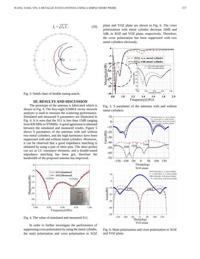
III. RESULTS AND DISCUSSION The prototype of the antenna is fabricated which is
shown in Fig. 4. The Key-sight E5080A vector network
analyzer is used to measure the scattering performance.
Simulated and measured S parameters are illustrated in
Fig. 4. It is seen that the S11 is less than 15dB ranging
from 830 MHz to 970MHz. A good agreement is obtained
between the simulated and measured results. Figure 5
shows S parameters of the antennas with and without
two metal cylinders, and the high harmonics have been
suppressed with and without metal cylinders. Moreover,
it can be observed that a good impedance matching is
obtained by using a pair of short pins. The short probes
can act as LC resonance elements, and a double-tuned
impedance matching has been got, therefore the
bandwidth of the proposed antenna has improved.
Fig. 4. The value of simulated and measured S11.
In order to further investigate the performance of
suppressing cross polarization by using the metal cylinder,
the main polarization and cross polarization in XOZ
plane and YOZ plane are shown in Fig. 6. The cross
polarizations with metal cylinder decrease 10dB and
5dB, in XOZ and YOZ plane, respectively. Therefore,
the cross polarization has been suppressed with two
metal cylinders obviously.
Fig. 5. S parameter of the antennas with and without
metal cylinders.
XOZ-plane
YOZ-plane
Fig. 6. Main polarization and cross polarization in XOZ
and YOZ plane.
WANG, YANG, YIN: A METALLIC PATCH ANTENNA USING A SIMPLE SHORT PROBE 117

Parameter analysis has been shown to describe the
design mechanism of the wideband RFID antenna. In
Figs. 7-9, the S parameter for the proposed antenna with
different values of W3, h, Wr are shown, respectively.
Figure 7 illustrates the effects of the size of the U slot. It
is found that the low frequency changes fiercely with
high frequency invariance. In Fig. 8, the impedance
match performance has improved with the distance of
the two short pins changing, while the dual resonant
frequencies are almost unchanged. In Fig. 9, as the value
of h changes from 21mm to 31mm, both of the dual
resonator frequencies shift down to the low frequency,
while the bandwidth of the antenna changes slightly.
Fig. 7. Influence of U slot on the value of S11.
Fig. 8. Influence of two short pins on the value of S11.
The radiation patterns, gains and efficiencies are
tested by using a SATIMO system. Figures 10-12 show
the measured and simulated far field radiation patterns
for XOZ-plane and YOZ-plane at 840MHz, 900MHz,
and 950MHz in the desired band. It is clear that stable
radiation patterns are obtained, and 3 dB beam width are
both 65◦ for XOZ and YOZ plane.
Fig. 9. Influence of height on the value of S11.
The simulated and measured gains and efficiencies
of the proposed antenna are shown in Fig. 13 and Fig.
14. It is found that the gains of the proposed antenna
are more than 9dBi in the desire band. Meanwhile, the
simulated and measured efficiencies of the proposed
antenna are more than 80%. Therefore, it can satisfy the
traditional requirement in the whole UHF band.
Fig. 10 Simulated and measured radiation patterns for
XOZ plane and YOZ plane at 840MHz.
Fig. 11. Simulated and measured radiation patterns for
XOZ plane and YOZ plane at 900MHz.
ACES JOURNAL, Vol. 34, No. 1, January 2019118

Fig. 12. Simulated and measured radiation patterns for
XOZ plane and YOZ plane at 960MHz.
Fig. 13. Simulated and measured gains for the proposed
antenna.
Fig. 14. Simulated and measured efficiencies for the
proposed antenna.
The sizes, gain performance, and the bandwidth of
the proposed RFID antenna have been compared with
several other antennas in Table 1. By observing these
data, all the performances of the designed antenna are
superior to those of other reference antenna. Accurate
comparative data are as follows.
Table 1: Performance of several other antennas
ANT BW(VSWR<1.5)
(MHz)
Gain
(dBi) Height
Ref. [8] 1620-1800 (10.53%) 0.125λ
Ref. [9] 2170-2580 (17.2%) 0.08λ
Ref. [10] 818-964 (16.3%) 0.125λ
Ref. [6] 4200-5400 (25%) 0.14λ
Prop. 830-970 (16.8%) 0.06λ
IV. COPYRIGHT AND RELEASE
INFORMATION No conflict of interest exits in the submission of this
manuscript. All authors have seen the manuscript and
approved to submit to your journal.
V. CONCLUSION A wideband metal patch antenna basing on double-
tuned impedance match is proposed. Owing to the
common effect of the short probes and the U slot, the
impedance matching bandwidth is improved ranging
from 830MHz to 970 MHz (S11<-15). Moreover, high
harmonics and cross polarization have been suppressed
with the effect of metal cylinders. A good radiation
performance has been obtained for the proposed antenna.
Gains is more than 9dBi in the desired band, and the
efficiencies are about 80%. Moreover, the radiation
patterns are satisfying in a wide band, and 3-dB beam
width are both 65◦ in XOZ and YOZ plane. Therefore,
stable gain, low cost, compact structure, and easy
manufacturing make the proposed antenna become a
good candidate for UHF RFID applications.
REFERENCES [1] Z. Xing, Z. Zhang, and K. Wei, “One terminal
improving method of open-circuit near-field antenna
of UHF RFID system,” Journal of Electromagnetic
Waves & Applications, vol. 28, no. 3, pp. 306-315,
2014.
[2] A. A. Deshmukh and K. P. Ray, “Broadband
proximity-fed modified rectangular microstrip
antennas,” IEEE Antennas Propag., Mag, vol. 53,
no. 5, pp. 41-56, Oct. 2011.
[3] V. G. Kasabegoudar and K. J. Vinoy, “Coplanar
capacitively coupled probe fed microstrip antennas
for wideband applications,” IEEE Trans. Antennas
Propag., vol. 58, no. 10, pp. 3131-3138, Oct. 2010.
[4] S. Liu, S. S. Qi, W. Wu, and D. G. Fang, “Single-
feed dual-band single/dual-beam U-slot antenna
for wireless communication application,” IEEE
Trans. Antennas Propag., vol. 63, no. 8, pp. 3759-
WANG, YANG, YIN: A METALLIC PATCH ANTENNA USING A SIMPLE SHORT PROBE 119

3764, Aug. 2015.
[5] K. F. Tong and T. P. Wong, “Circularly polarized
U-slot antenna,” IEEE Trans. Antennas Propag.,
vol. 55, no. 8, pp. 2382-2385, Aug. 2007.
[6] E. Nishiyama and M. Aikawa, “Wide-band and
high-gain microstrip antenna with thick parasitic
patch substrate,” in Proc. IEEE Antennas Propag.
Soc. Int. Symp. (APSURSI), pp. 273-276, June 2004.
[7] M. Arrawatia, M. S. Baghini, and G. Kumar,
“Differential microstrip antenna for RF energy
harvesting,” IEEE Trans. Antennas Propag., vol.
63, no. 4, pp. 1581-1588, Apr. 2015.
[8] X. H. Tang, K. L. Lau, Q. Xue, and Y. L. Long,
“Miniature circularly polarised patch antenna,”
Electron. Lett., vol. 46, no. 6, pp. 391-392, Mar.
2010.
[9] A. Khidre, K. F. Lee, F. Yang, and A. Elsherbeni,
“Wideband circularly polarized E-shaped patch
antenna for wireless applications,” IEEE Antennas
Propag. Mag., vol. 52, no. 5, pp. 219-229, Oct.
2010.
[10] Nasimuddin, Z. N. Chen, and X. M. Qing, “Dual-
band circularly polarized S-shaped slotted patch
antenna with a small frequency-ratio,” IEEE Trans.
Antennas Propag., vol. 58, no. 6, pp. 2112-2115,
June 2010.
[11] F Yang, X. X. Zhang, X. N. Ye, and R. S. Yahya,
“Wide-band E-shaped patch antennas for wireless
communication,” IEEE Transactions on Antennas
and Propagation, vol. 49, no. 7, pp. 1094-1100,
June 2010.
[12] K. Yu, Y. S. Li, and W. H. Yu. “Wide-band E-
shaped patch antennas for wireless communication,”
IEEE Transactions on Antennas and Propagation,
vol. 32, no. 5, pp. 424-429, May 2017.
Zi-Yang Wang was born in Henan
Province, China, in 1991. He received
the Ph.D. degree in Electromagnetic
Wave and Microwave Technology
from Xidian University, Xi’an, P. R.
China, in 2018. He is currently doing
postdoctoral research at National
Laboratory for Information Science
and Technology, Department of Electronic Engineering,
in Tsinghua University. His research interests include
the design of metamaterial and meta-surface, array
decoupling, MIMO, RFID antennas, wideband antenna.
Zhao Yang was born in Shanxi
Province, China, in 1992. He received
the B.S. degree from Xidian
University, Xi’an, China, in 2014.
He is currently pursuing the M.S.
degree in Electromagnetic Field
and Microwave Technology from
the Key Laboratory of Science
and Technology on Antennas and Microwaves, Xidian
University, Xi’an, China.
Ying-Zeng Yin received the B.S.
degree and the M.S. degree and
Ph.D. degree in Electromagnetic
Wave and Microwave Technology
from Xidian University, Xi’an,
China, in 1987, 1990, and 2002,
respectively. From 1990 to 1992,
he was a Research Assistant and an
Instructor at the Institute of Antennas and Electromagnetic
Scattering, Xidian University. From 1992 to 1996, he
was an Associate Professor in the Department of
Electromagnetic Engineering, Xidian University. Since
2004, he has been a Professor at Xidian University.
His research interests include design of microstrip
antennas, artificial magnetic conductors, phased array
antennas, and computer aided design for antennas.
ACES JOURNAL, Vol. 34, No. 1, January 2019120